EP0001407B1 - Tubular filter elements with improved side seam seal - Google Patents
Tubular filter elements with improved side seam sealDownload PDFInfo
- Publication number
- EP0001407B1 EP0001407B1EP78100892AEP78100892AEP0001407B1EP 0001407 B1EP0001407 B1EP 0001407B1EP 78100892 AEP78100892 AEP 78100892AEP 78100892 AEP78100892 AEP 78100892AEP 0001407 B1EP0001407 B1EP 0001407B1
- Authority
- EP
- European Patent Office
- Prior art keywords
- filter
- side seam
- seal
- tubular
- sheet
- Prior art date
- Legal status (The legal status is an assumption and is not a legal conclusion. Google has not performed a legal analysis and makes no representation as to the accuracy of the status listed.)
- Expired
Links
- 239000000463materialSubstances0.000claimsdescription68
- 239000011148porous materialSubstances0.000claimsdescription20
- 229920001169thermoplasticPolymers0.000claimsdescription18
- 239000004416thermosoftening plasticSubstances0.000claimsdescription18
- 239000007788liquidSubstances0.000claimsdescription11
- 239000012260resinous materialSubstances0.000claimsdescription8
- 238000007789sealingMethods0.000claimsdescription6
- 230000000903blocking effectEffects0.000claimsdescription4
- 229920003002synthetic resinPolymers0.000claimsdescription3
- 239000000057synthetic resinSubstances0.000claimsdescription3
- 239000010410layerSubstances0.000description39
- -1polypropylenePolymers0.000description26
- 239000004743PolypropyleneSubstances0.000description25
- 229920001155polypropylenePolymers0.000description25
- 229920005989resinPolymers0.000description20
- 239000011347resinSubstances0.000description20
- 239000007767bonding agentSubstances0.000description15
- 239000012530fluidSubstances0.000description15
- 239000000853adhesiveSubstances0.000description13
- 230000001070adhesive effectEffects0.000description13
- 239000000835fiberSubstances0.000description10
- 239000012815thermoplastic materialSubstances0.000description10
- 238000000034methodMethods0.000description9
- 239000004033plasticSubstances0.000description7
- 229920003023plasticPolymers0.000description7
- 239000002131composite materialSubstances0.000description6
- 238000010438heat treatmentMethods0.000description6
- 238000006116polymerization reactionMethods0.000description5
- 238000004519manufacturing processMethods0.000description4
- 239000011236particulate materialSubstances0.000description4
- 239000007787solidSubstances0.000description4
- 230000015572biosynthetic processEffects0.000description3
- 239000011248coating agentSubstances0.000description3
- 238000000576coating methodMethods0.000description3
- 238000001816coolingMethods0.000description3
- 239000004753textileSubstances0.000description3
- 229920005992thermoplastic resinPolymers0.000description3
- 244000025254Cannabis sativaSpecies0.000description2
- 235000012766Cannabis sativa ssp. sativa var. sativaNutrition0.000description2
- 235000012765Cannabis sativa ssp. sativa var. spontaneaNutrition0.000description2
- 229920000742CottonPolymers0.000description2
- 229920000297RayonPolymers0.000description2
- 229920001807Urea-formaldehydePolymers0.000description2
- 235000009120camoNutrition0.000description2
- 235000005607chanvre indienNutrition0.000description2
- 239000003153chemical reaction reagentSubstances0.000description2
- 239000003795chemical substances by applicationSubstances0.000description2
- 239000002657fibrous materialSubstances0.000description2
- 238000001914filtrationMethods0.000description2
- 239000011487hempSubstances0.000description2
- 239000012943hotmeltSubstances0.000description2
- 229910052751metalInorganic materials0.000description2
- 239000002184metalSubstances0.000description2
- 229920001568phenolic resinPolymers0.000description2
- 229920000647polyepoxidePolymers0.000description2
- 239000011241protective layerSubstances0.000description2
- 229920001187thermosetting polymerPolymers0.000description2
- 238000011144upstream manufacturingMethods0.000description2
- 241000894006BacteriaSpecies0.000description1
- 229920008347Cellulose acetate propionatePolymers0.000description1
- 229920003043Cellulose fiberPolymers0.000description1
- 241000288673ChiropteraSpecies0.000description1
- 240000000491Corchorus aestuansSpecies0.000description1
- 235000011777Corchorus aestuansNutrition0.000description1
- 235000010862Corchorus capsularisNutrition0.000description1
- 229920001732LignosulfonatePolymers0.000description1
- 229920000877Melamine resinPolymers0.000description1
- 239000004952PolyamideSubstances0.000description1
- 239000004698PolyethyleneSubstances0.000description1
- 229920001328Polyvinylidene chloridePolymers0.000description1
- 240000004808Saccharomyces cerevisiaeSpecies0.000description1
- 229920002494ZeinPolymers0.000description1
- 230000001464adherent effectEffects0.000description1
- 239000012790adhesive layerSubstances0.000description1
- 229920000615alginic acidPolymers0.000description1
- 235000010443alginic acidNutrition0.000description1
- 239000010425asbestosSubstances0.000description1
- 239000005018caseinSubstances0.000description1
- BECPQYXYKAMYBN-UHFFFAOYSA-Ncasein, tech.Chemical compoundNCCCCC(C(O)=O)N=C(O)C(CC(O)=O)N=C(O)C(CCC(O)=N)N=C(O)C(CC(C)C)N=C(O)C(CCC(O)=O)N=C(O)C(CC(O)=O)N=C(O)C(CCC(O)=O)N=C(O)C(C(C)O)N=C(O)C(CCC(O)=N)N=C(O)C(CCC(O)=N)N=C(O)C(CCC(O)=N)N=C(O)C(CCC(O)=O)N=C(O)C(CCC(O)=O)N=C(O)C(COP(O)(O)=O)N=C(O)C(CCC(O)=N)N=C(O)C(N)CC1=CC=CC=C1BECPQYXYKAMYBN-UHFFFAOYSA-N0.000description1
- 235000021240caseinsNutrition0.000description1
- 229920002678cellulosePolymers0.000description1
- 239000001913celluloseSubstances0.000description1
- 229920002301cellulose acetatePolymers0.000description1
- 238000010276constructionMethods0.000description1
- 238000011109contaminationMethods0.000description1
- 238000005260corrosionMethods0.000description1
- 230000007797corrosionEffects0.000description1
- 238000004132cross linkingMethods0.000description1
- 230000000994depressogenic effectEffects0.000description1
- NJLLQSBAHIKGKF-UHFFFAOYSA-Ndipotassium dioxido(oxo)titaniumChemical compound[K+].[K+].[O-][Ti]([O-])=ONJLLQSBAHIKGKF-UHFFFAOYSA-N0.000description1
- 239000002355dual-layerSubstances0.000description1
- 229920001971elastomerPolymers0.000description1
- 239000004744fabricSubstances0.000description1
- 239000000945fillerSubstances0.000description1
- SLGWESQGEUXWJQ-UHFFFAOYSA-Nformaldehyde;phenolChemical compoundO=C.OC1=CC=CC=C1SLGWESQGEUXWJQ-UHFFFAOYSA-N0.000description1
- 239000011521glassSubstances0.000description1
- 239000008187granular materialSubstances0.000description1
- 238000005470impregnationMethods0.000description1
- 238000010348incorporationMethods0.000description1
- 239000012442inert solventSubstances0.000description1
- 239000000155meltSubstances0.000description1
- 239000011490mineral woolSubstances0.000description1
- 238000002156mixingMethods0.000description1
- 210000000050mohairAnatomy0.000description1
- 239000012768molten materialSubstances0.000description1
- 230000003287optical effectEffects0.000description1
- 230000000149penetrating effectEffects0.000description1
- 239000012466permeateSubstances0.000description1
- 239000000049pigmentSubstances0.000description1
- 229920002239polyacrylonitrilePolymers0.000description1
- 229920002647polyamidePolymers0.000description1
- 229920000728polyesterPolymers0.000description1
- 229920001225polyester resinPolymers0.000description1
- 239000004645polyester resinSubstances0.000description1
- 229920000573polyethylenePolymers0.000description1
- 229920000642polymerPolymers0.000description1
- 230000000379polymerizing effectEffects0.000description1
- ODGAOXROABLFNM-UHFFFAOYSA-NpolynoxylinChemical compoundO=C.NC(N)=OODGAOXROABLFNM-UHFFFAOYSA-N0.000description1
- 229920000915polyvinyl chloridePolymers0.000description1
- 239000004800polyvinyl chlorideSubstances0.000description1
- 239000005033polyvinylidene chlorideSubstances0.000description1
- 239000002964rayonSubstances0.000description1
- 229910052895riebeckiteInorganic materials0.000description1
- 239000005060rubberSubstances0.000description1
- 239000012945sealing adhesiveSubstances0.000description1
- 239000002356single layerSubstances0.000description1
- 238000007711solidificationMethods0.000description1
- 230000008023solidificationEffects0.000description1
- 125000006850spacer groupChemical group0.000description1
- 238000003892spreadingMethods0.000description1
- 150000003505terpenesChemical class0.000description1
- 235000007586terpenesNutrition0.000description1
- XLYOFNOQVPJJNP-UHFFFAOYSA-NwaterSubstancesOXLYOFNOQVPJJNP-UHFFFAOYSA-N0.000description1
- 210000002268woolAnatomy0.000description1
- 239000005019zeinSubstances0.000description1
- 229940093612zeinDrugs0.000description1
Images


Classifications
- B—PERFORMING OPERATIONS; TRANSPORTING
- B29—WORKING OF PLASTICS; WORKING OF SUBSTANCES IN A PLASTIC STATE IN GENERAL
- B29C—SHAPING OR JOINING OF PLASTICS; SHAPING OF MATERIAL IN A PLASTIC STATE, NOT OTHERWISE PROVIDED FOR; AFTER-TREATMENT OF THE SHAPED PRODUCTS, e.g. REPAIRING
- B29C66/00—General aspects of processes or apparatus for joining preformed parts
- B29C66/70—General aspects of processes or apparatus for joining preformed parts characterised by the composition, physical properties or the structure of the material of the parts to be joined; Joining with non-plastics material
- B29C66/72—General aspects of processes or apparatus for joining preformed parts characterised by the composition, physical properties or the structure of the material of the parts to be joined; Joining with non-plastics material characterised by the structure of the material of the parts to be joined
- B29C66/723—General aspects of processes or apparatus for joining preformed parts characterised by the composition, physical properties or the structure of the material of the parts to be joined; Joining with non-plastics material characterised by the structure of the material of the parts to be joined being multi-layered
- B—PERFORMING OPERATIONS; TRANSPORTING
- B01—PHYSICAL OR CHEMICAL PROCESSES OR APPARATUS IN GENERAL
- B01D—SEPARATION
- B01D29/00—Filters with filtering elements stationary during filtration, e.g. pressure or suction filters, not covered by groups B01D24/00 - B01D27/00; Filtering elements therefor
- B01D29/11—Filters with filtering elements stationary during filtration, e.g. pressure or suction filters, not covered by groups B01D24/00 - B01D27/00; Filtering elements therefor with bag, cage, hose, tube, sleeve or like filtering elements
- B01D29/111—Making filtering elements
- B—PERFORMING OPERATIONS; TRANSPORTING
- B01—PHYSICAL OR CHEMICAL PROCESSES OR APPARATUS IN GENERAL
- B01D—SEPARATION
- B01D29/00—Filters with filtering elements stationary during filtration, e.g. pressure or suction filters, not covered by groups B01D24/00 - B01D27/00; Filtering elements therefor
- B01D29/11—Filters with filtering elements stationary during filtration, e.g. pressure or suction filters, not covered by groups B01D24/00 - B01D27/00; Filtering elements therefor with bag, cage, hose, tube, sleeve or like filtering elements
- B01D29/13—Supported filter elements
- B01D29/15—Supported filter elements arranged for inward flow filtration
- B01D29/21—Supported filter elements arranged for inward flow filtration with corrugated, folded or wound sheets
- B—PERFORMING OPERATIONS; TRANSPORTING
- B29—WORKING OF PLASTICS; WORKING OF SUBSTANCES IN A PLASTIC STATE IN GENERAL
- B29C—SHAPING OR JOINING OF PLASTICS; SHAPING OF MATERIAL IN A PLASTIC STATE, NOT OTHERWISE PROVIDED FOR; AFTER-TREATMENT OF THE SHAPED PRODUCTS, e.g. REPAIRING
- B29C65/00—Joining or sealing of preformed parts, e.g. welding of plastics materials; Apparatus therefor
- B29C65/02—Joining or sealing of preformed parts, e.g. welding of plastics materials; Apparatus therefor by heating, with or without pressure
- B29C65/18—Joining or sealing of preformed parts, e.g. welding of plastics materials; Apparatus therefor by heating, with or without pressure using heated tools
- B—PERFORMING OPERATIONS; TRANSPORTING
- B29—WORKING OF PLASTICS; WORKING OF SUBSTANCES IN A PLASTIC STATE IN GENERAL
- B29C—SHAPING OR JOINING OF PLASTICS; SHAPING OF MATERIAL IN A PLASTIC STATE, NOT OTHERWISE PROVIDED FOR; AFTER-TREATMENT OF THE SHAPED PRODUCTS, e.g. REPAIRING
- B29C65/00—Joining or sealing of preformed parts, e.g. welding of plastics materials; Apparatus therefor
- B29C65/48—Joining or sealing of preformed parts, e.g. welding of plastics materials; Apparatus therefor using adhesives, i.e. using supplementary joining material; solvent bonding
- B29C65/4805—Joining or sealing of preformed parts, e.g. welding of plastics materials; Apparatus therefor using adhesives, i.e. using supplementary joining material; solvent bonding characterised by the type of adhesives
- B29C65/481—Non-reactive adhesives, e.g. physically hardening adhesives
- B29C65/4815—Hot melt adhesives, e.g. thermoplastic adhesives
- B—PERFORMING OPERATIONS; TRANSPORTING
- B29—WORKING OF PLASTICS; WORKING OF SUBSTANCES IN A PLASTIC STATE IN GENERAL
- B29C—SHAPING OR JOINING OF PLASTICS; SHAPING OF MATERIAL IN A PLASTIC STATE, NOT OTHERWISE PROVIDED FOR; AFTER-TREATMENT OF THE SHAPED PRODUCTS, e.g. REPAIRING
- B29C65/00—Joining or sealing of preformed parts, e.g. welding of plastics materials; Apparatus therefor
- B29C65/48—Joining or sealing of preformed parts, e.g. welding of plastics materials; Apparatus therefor using adhesives, i.e. using supplementary joining material; solvent bonding
- B29C65/50—Joining or sealing of preformed parts, e.g. welding of plastics materials; Apparatus therefor using adhesives, i.e. using supplementary joining material; solvent bonding using adhesive tape, e.g. thermoplastic tape; using threads or the like
- B29C65/5064—Joining or sealing of preformed parts, e.g. welding of plastics materials; Apparatus therefor using adhesives, i.e. using supplementary joining material; solvent bonding using adhesive tape, e.g. thermoplastic tape; using threads or the like of particular form, e.g. being C-shaped, T-shaped
- B29C65/5071—Joining or sealing of preformed parts, e.g. welding of plastics materials; Apparatus therefor using adhesives, i.e. using supplementary joining material; solvent bonding using adhesive tape, e.g. thermoplastic tape; using threads or the like of particular form, e.g. being C-shaped, T-shaped and being composed by one single element
- B—PERFORMING OPERATIONS; TRANSPORTING
- B29—WORKING OF PLASTICS; WORKING OF SUBSTANCES IN A PLASTIC STATE IN GENERAL
- B29C—SHAPING OR JOINING OF PLASTICS; SHAPING OF MATERIAL IN A PLASTIC STATE, NOT OTHERWISE PROVIDED FOR; AFTER-TREATMENT OF THE SHAPED PRODUCTS, e.g. REPAIRING
- B29C65/00—Joining or sealing of preformed parts, e.g. welding of plastics materials; Apparatus therefor
- B29C65/48—Joining or sealing of preformed parts, e.g. welding of plastics materials; Apparatus therefor using adhesives, i.e. using supplementary joining material; solvent bonding
- B29C65/50—Joining or sealing of preformed parts, e.g. welding of plastics materials; Apparatus therefor using adhesives, i.e. using supplementary joining material; solvent bonding using adhesive tape, e.g. thermoplastic tape; using threads or the like
- B29C65/5064—Joining or sealing of preformed parts, e.g. welding of plastics materials; Apparatus therefor using adhesives, i.e. using supplementary joining material; solvent bonding using adhesive tape, e.g. thermoplastic tape; using threads or the like of particular form, e.g. being C-shaped, T-shaped
- B29C65/5085—Joining or sealing of preformed parts, e.g. welding of plastics materials; Apparatus therefor using adhesives, i.e. using supplementary joining material; solvent bonding using adhesive tape, e.g. thermoplastic tape; using threads or the like of particular form, e.g. being C-shaped, T-shaped and comprising grooves, e.g. being E-shaped, H-shaped
- B—PERFORMING OPERATIONS; TRANSPORTING
- B29—WORKING OF PLASTICS; WORKING OF SUBSTANCES IN A PLASTIC STATE IN GENERAL
- B29C—SHAPING OR JOINING OF PLASTICS; SHAPING OF MATERIAL IN A PLASTIC STATE, NOT OTHERWISE PROVIDED FOR; AFTER-TREATMENT OF THE SHAPED PRODUCTS, e.g. REPAIRING
- B29C66/00—General aspects of processes or apparatus for joining preformed parts
- B29C66/01—General aspects dealing with the joint area or with the area to be joined
- B29C66/05—Particular design of joint configurations
- B29C66/10—Particular design of joint configurations particular design of the joint cross-sections
- B29C66/11—Joint cross-sections comprising a single joint-segment, i.e. one of the parts to be joined comprising a single joint-segment in the joint cross-section
- B29C66/112—Single lapped joints
- B29C66/1122—Single lap to lap joints, i.e. overlap joints
- B—PERFORMING OPERATIONS; TRANSPORTING
- B29—WORKING OF PLASTICS; WORKING OF SUBSTANCES IN A PLASTIC STATE IN GENERAL
- B29C—SHAPING OR JOINING OF PLASTICS; SHAPING OF MATERIAL IN A PLASTIC STATE, NOT OTHERWISE PROVIDED FOR; AFTER-TREATMENT OF THE SHAPED PRODUCTS, e.g. REPAIRING
- B29C66/00—General aspects of processes or apparatus for joining preformed parts
- B29C66/40—General aspects of joining substantially flat articles, e.g. plates, sheets or web-like materials; Making flat seams in tubular or hollow articles; Joining single elements to substantially flat surfaces
- B29C66/41—Joining substantially flat articles ; Making flat seams in tubular or hollow articles
- B29C66/43—Joining a relatively small portion of the surface of said articles
- B29C66/432—Joining a relatively small portion of the surface of said articles for making tubular articles or closed loops, e.g. by joining several sheets ; for making hollow articles or hollow preforms
- B29C66/4322—Joining a relatively small portion of the surface of said articles for making tubular articles or closed loops, e.g. by joining several sheets ; for making hollow articles or hollow preforms by joining a single sheet to itself
- B—PERFORMING OPERATIONS; TRANSPORTING
- B29—WORKING OF PLASTICS; WORKING OF SUBSTANCES IN A PLASTIC STATE IN GENERAL
- B29C—SHAPING OR JOINING OF PLASTICS; SHAPING OF MATERIAL IN A PLASTIC STATE, NOT OTHERWISE PROVIDED FOR; AFTER-TREATMENT OF THE SHAPED PRODUCTS, e.g. REPAIRING
- B29C66/00—General aspects of processes or apparatus for joining preformed parts
- B29C66/50—General aspects of joining tubular articles; General aspects of joining long products, i.e. bars or profiled elements; General aspects of joining single elements to tubular articles, hollow articles or bars; General aspects of joining several hollow-preforms to form hollow or tubular articles
- B29C66/51—Joining tubular articles, profiled elements or bars; Joining single elements to tubular articles, hollow articles or bars; Joining several hollow-preforms to form hollow or tubular articles
- B29C66/53—Joining single elements to tubular articles, hollow articles or bars
- B29C66/534—Joining single elements to open ends of tubular or hollow articles or to the ends of bars
- B29C66/5344—Joining single elements to open ends of tubular or hollow articles or to the ends of bars said single elements being substantially annular, i.e. of finite length, e.g. joining flanges to tube ends
- B—PERFORMING OPERATIONS; TRANSPORTING
- B29—WORKING OF PLASTICS; WORKING OF SUBSTANCES IN A PLASTIC STATE IN GENERAL
- B29C—SHAPING OR JOINING OF PLASTICS; SHAPING OF MATERIAL IN A PLASTIC STATE, NOT OTHERWISE PROVIDED FOR; AFTER-TREATMENT OF THE SHAPED PRODUCTS, e.g. REPAIRING
- B29C66/00—General aspects of processes or apparatus for joining preformed parts
- B29C66/50—General aspects of joining tubular articles; General aspects of joining long products, i.e. bars or profiled elements; General aspects of joining single elements to tubular articles, hollow articles or bars; General aspects of joining several hollow-preforms to form hollow or tubular articles
- B29C66/61—Joining from or joining on the inside
- B29C66/612—Making circumferential joints
- B—PERFORMING OPERATIONS; TRANSPORTING
- B29—WORKING OF PLASTICS; WORKING OF SUBSTANCES IN A PLASTIC STATE IN GENERAL
- B29C—SHAPING OR JOINING OF PLASTICS; SHAPING OF MATERIAL IN A PLASTIC STATE, NOT OTHERWISE PROVIDED FOR; AFTER-TREATMENT OF THE SHAPED PRODUCTS, e.g. REPAIRING
- B29C66/00—General aspects of processes or apparatus for joining preformed parts
- B29C66/80—General aspects of machine operations or constructions and parts thereof
- B29C66/83—General aspects of machine operations or constructions and parts thereof characterised by the movement of the joining or pressing tools
- B29C66/832—Reciprocating joining or pressing tools
- B29C66/8322—Joining or pressing tools reciprocating along one axis
- B29C66/83221—Joining or pressing tools reciprocating along one axis cooperating reciprocating tools, each tool reciprocating along one axis
- B—PERFORMING OPERATIONS; TRANSPORTING
- B29—WORKING OF PLASTICS; WORKING OF SUBSTANCES IN A PLASTIC STATE IN GENERAL
- B29C—SHAPING OR JOINING OF PLASTICS; SHAPING OF MATERIAL IN A PLASTIC STATE, NOT OTHERWISE PROVIDED FOR; AFTER-TREATMENT OF THE SHAPED PRODUCTS, e.g. REPAIRING
- B29C53/00—Shaping by bending, folding, twisting, straightening or flattening; Apparatus therefor
- B29C53/36—Bending and joining, e.g. for making hollow articles
- B29C53/38—Bending and joining, e.g. for making hollow articles by bending sheets or strips at right angles to the longitudinal axis of the article being formed and joining the edges
- B29C53/40—Bending and joining, e.g. for making hollow articles by bending sheets or strips at right angles to the longitudinal axis of the article being formed and joining the edges for articles of definite length, i.e. discrete articles
- B—PERFORMING OPERATIONS; TRANSPORTING
- B29—WORKING OF PLASTICS; WORKING OF SUBSTANCES IN A PLASTIC STATE IN GENERAL
- B29C—SHAPING OR JOINING OF PLASTICS; SHAPING OF MATERIAL IN A PLASTIC STATE, NOT OTHERWISE PROVIDED FOR; AFTER-TREATMENT OF THE SHAPED PRODUCTS, e.g. REPAIRING
- B29C65/00—Joining or sealing of preformed parts, e.g. welding of plastics materials; Apparatus therefor
- B29C65/48—Joining or sealing of preformed parts, e.g. welding of plastics materials; Apparatus therefor using adhesives, i.e. using supplementary joining material; solvent bonding
- B29C65/4805—Joining or sealing of preformed parts, e.g. welding of plastics materials; Apparatus therefor using adhesives, i.e. using supplementary joining material; solvent bonding characterised by the type of adhesives
- B29C65/481—Non-reactive adhesives, e.g. physically hardening adhesives
- B29C65/4825—Pressure sensitive adhesives
- B—PERFORMING OPERATIONS; TRANSPORTING
- B29—WORKING OF PLASTICS; WORKING OF SUBSTANCES IN A PLASTIC STATE IN GENERAL
- B29C—SHAPING OR JOINING OF PLASTICS; SHAPING OF MATERIAL IN A PLASTIC STATE, NOT OTHERWISE PROVIDED FOR; AFTER-TREATMENT OF THE SHAPED PRODUCTS, e.g. REPAIRING
- B29C65/00—Joining or sealing of preformed parts, e.g. welding of plastics materials; Apparatus therefor
- B29C65/48—Joining or sealing of preformed parts, e.g. welding of plastics materials; Apparatus therefor using adhesives, i.e. using supplementary joining material; solvent bonding
- B29C65/4805—Joining or sealing of preformed parts, e.g. welding of plastics materials; Apparatus therefor using adhesives, i.e. using supplementary joining material; solvent bonding characterised by the type of adhesives
- B29C65/483—Reactive adhesives, e.g. chemically curing adhesives
- B29C65/4835—Heat curing adhesives
- B—PERFORMING OPERATIONS; TRANSPORTING
- B29—WORKING OF PLASTICS; WORKING OF SUBSTANCES IN A PLASTIC STATE IN GENERAL
- B29C—SHAPING OR JOINING OF PLASTICS; SHAPING OF MATERIAL IN A PLASTIC STATE, NOT OTHERWISE PROVIDED FOR; AFTER-TREATMENT OF THE SHAPED PRODUCTS, e.g. REPAIRING
- B29C66/00—General aspects of processes or apparatus for joining preformed parts
- B29C66/70—General aspects of processes or apparatus for joining preformed parts characterised by the composition, physical properties or the structure of the material of the parts to be joined; Joining with non-plastics material
- B29C66/71—General aspects of processes or apparatus for joining preformed parts characterised by the composition, physical properties or the structure of the material of the parts to be joined; Joining with non-plastics material characterised by the composition of the plastics material of the parts to be joined
- B—PERFORMING OPERATIONS; TRANSPORTING
- B29—WORKING OF PLASTICS; WORKING OF SUBSTANCES IN A PLASTIC STATE IN GENERAL
- B29C—SHAPING OR JOINING OF PLASTICS; SHAPING OF MATERIAL IN A PLASTIC STATE, NOT OTHERWISE PROVIDED FOR; AFTER-TREATMENT OF THE SHAPED PRODUCTS, e.g. REPAIRING
- B29C66/00—General aspects of processes or apparatus for joining preformed parts
- B29C66/70—General aspects of processes or apparatus for joining preformed parts characterised by the composition, physical properties or the structure of the material of the parts to be joined; Joining with non-plastics material
- B29C66/72—General aspects of processes or apparatus for joining preformed parts characterised by the composition, physical properties or the structure of the material of the parts to be joined; Joining with non-plastics material characterised by the structure of the material of the parts to be joined
- B29C66/723—General aspects of processes or apparatus for joining preformed parts characterised by the composition, physical properties or the structure of the material of the parts to be joined; Joining with non-plastics material characterised by the structure of the material of the parts to be joined being multi-layered
- B29C66/7232—General aspects of processes or apparatus for joining preformed parts characterised by the composition, physical properties or the structure of the material of the parts to be joined; Joining with non-plastics material characterised by the structure of the material of the parts to be joined being multi-layered comprising a non-plastics layer
- B29C66/72324—General aspects of processes or apparatus for joining preformed parts characterised by the composition, physical properties or the structure of the material of the parts to be joined; Joining with non-plastics material characterised by the structure of the material of the parts to be joined being multi-layered comprising a non-plastics layer consisting of inorganic materials not provided for in B29C66/72321 - B29C66/72322
- B29C66/72326—Glass
- B—PERFORMING OPERATIONS; TRANSPORTING
- B29—WORKING OF PLASTICS; WORKING OF SUBSTANCES IN A PLASTIC STATE IN GENERAL
- B29C—SHAPING OR JOINING OF PLASTICS; SHAPING OF MATERIAL IN A PLASTIC STATE, NOT OTHERWISE PROVIDED FOR; AFTER-TREATMENT OF THE SHAPED PRODUCTS, e.g. REPAIRING
- B29C66/00—General aspects of processes or apparatus for joining preformed parts
- B29C66/70—General aspects of processes or apparatus for joining preformed parts characterised by the composition, physical properties or the structure of the material of the parts to be joined; Joining with non-plastics material
- B29C66/72—General aspects of processes or apparatus for joining preformed parts characterised by the composition, physical properties or the structure of the material of the parts to be joined; Joining with non-plastics material characterised by the structure of the material of the parts to be joined
- B29C66/723—General aspects of processes or apparatus for joining preformed parts characterised by the composition, physical properties or the structure of the material of the parts to be joined; Joining with non-plastics material characterised by the structure of the material of the parts to be joined being multi-layered
- B29C66/7232—General aspects of processes or apparatus for joining preformed parts characterised by the composition, physical properties or the structure of the material of the parts to be joined; Joining with non-plastics material characterised by the structure of the material of the parts to be joined being multi-layered comprising a non-plastics layer
- B29C66/72327—General aspects of processes or apparatus for joining preformed parts characterised by the composition, physical properties or the structure of the material of the parts to be joined; Joining with non-plastics material characterised by the structure of the material of the parts to be joined being multi-layered comprising a non-plastics layer consisting of natural products or their composites, not provided for in B29C66/72321 - B29C66/72324
- B29C66/72328—Paper
- B—PERFORMING OPERATIONS; TRANSPORTING
- B29—WORKING OF PLASTICS; WORKING OF SUBSTANCES IN A PLASTIC STATE IN GENERAL
- B29L—INDEXING SCHEME ASSOCIATED WITH SUBCLASS B29C, RELATING TO PARTICULAR ARTICLES
- B29L2009/00—Layered products
- B—PERFORMING OPERATIONS; TRANSPORTING
- B29—WORKING OF PLASTICS; WORKING OF SUBSTANCES IN A PLASTIC STATE IN GENERAL
- B29L—INDEXING SCHEME ASSOCIATED WITH SUBCLASS B29C, RELATING TO PARTICULAR ARTICLES
- B29L2016/00—Articles with corrugations or pleats
- B—PERFORMING OPERATIONS; TRANSPORTING
- B29—WORKING OF PLASTICS; WORKING OF SUBSTANCES IN A PLASTIC STATE IN GENERAL
- B29L—INDEXING SCHEME ASSOCIATED WITH SUBCLASS B29C, RELATING TO PARTICULAR ARTICLES
- B29L2031/00—Other particular articles
- B29L2031/14—Filters
Definitions
- Cylindrical filter elementshave one or more filter sheets or layers formed in a cylindrical configuration, with the open ends of the cylinder closed off by end caps bonded to the ends of the filter sheets. It is essential that the end caps be bonded securely to all protions of the filter sheets, so as to compel fluid passing between the interior and the exterior of the filter cylinder to proceed by way of the filter sheets.
- Such cylindrical filter elementscan be aranged to accept fluid flow either form the inside out, or from the outside in, but in either case all flow must pass through the filter sheets.
- a bonding agent or adhesive strip or coatingbetween the opposed faces.
- the two outisde surfaces of the ends of the sheetare brought together.
- One or both of the opposed surfacesis coated with adhesive before the surfaces are brought into contact, and the seal is then formed by application of heat to set the adhesive.
- a sealis formed in which a layer of adhesive extends from end to end of the seam, and across the seam from the outer surface to the inner surface of the filter sheets, and this layer of adhesive is presented endwise to the filter cap.
- the adhesive systems used to bond the end caps to the ends of the side sealed packusually adhere very well to the filter media layers, since these are porous, and consequently absorb some of the adhesive, forming a good bond.
- the sameis not true in relation to the layer of adhesive of which the side seam is composed, and in many systems there is zero adhesion at this point. Consequently, it frequently happens that a poor seal is formed at the adhesive layer, with the result that a leakage path can be formed under fluid pressure across the filter element, since the adhesive extends form the outer surface to the inner surface of the filter across the seam. The result is a potential bypass route for fluid which does not pass through the filter.
- a potential leakage path of this sortcannot be tolerated in cylindrical filter elements in which the filter sheet is of a pore size such that the filter can be used in filtering out yeasts or bacteria.
- the development of such a leakage path in use under high fluid pressureeven if the fluid pressure be extraordinary and well beyond the normal fluid pressure, will result in organisms bypassing the filter, with possibly disastrous consequences.
- the resultis that for ultrafine filter use, it is not always possible to use cylindrical filter elements, particularly when high internal fluid pressures are apt to be encountered.
- Pall and Jasaitis U.S. patent No. 3867294, patented February 18, 1975,provide a cylindrical filter element comprising one or more layers of filter sheet material formed in a substantially cylindrical shape, and having opposite sheet end portions folded over with outer and inner end surfaces in adjacent relation and joined together in a side seam seal wherein portions of the sheet adjacent the sheet ends have one surface in face-to-face closely-abutting contact, extending to the end edges of the sheet, and the next-adjacent portions have the other surfaces opposite each other, extending beyond the end edges of the end portions of the sheet, and spaced apart by the foldedover abutting sheet ends, the opposed surfaces of the sheet ends and the end edges of the sheet ends defining a space therebetween, with a bonding agent in the space bonding the sheets together ot the end edges and the opposed surfaces of the sheet substantially without penetrating the face-to-face end portions of the sheet at the seam to the outer surface of the filter sheet.
- the sheet endsare exposed directly to the sealing adhesive, and since the ends of the fine filter sheet layer are similarly exposed, there is no hindrance to the accomplishment of a reliable seal to the ends of the fine filter sheet, and bypassing through the coarser protective layers cannot occur.
- a self-sustaining ribbon of bonding agentcan be used, of a thickness chosen to just fill the space between the ends of the filter sheet and the opposed next-adjacent surfaces.
- Application of heat through conventional meanscauses the ribbon to soften and melt, and produces a leak-proof bond throughout this space.
- the ribboncan be the type of resin which solidifies on cooling (»hot melt « adhesive) or it can be of the type which polymerizes on heating, but in either event it must reach a low enough viscosity for a sufficient time to penetrate slightly into the filter medium.
- a material which solidifies by polymerizingcan be applied as a liquid.
- the temporary application of a strip of pressure-sensitive tape across each endprevents the molten material from running out, and causes it to harden neatly flush with the ends of the cylinder.
- the use of a self-sustaining ribbon instead of a coatingmakes it pissible to obtain uniforms thickness and with of the bonding agent throught this space, so that the bonding agent layer is absolutely uniform form end to end the filter cylinder.
- a tubular corrugated filter elementcomprising at least one layer of filter sheet material formed in a substantial tubular shape and having the side seam edges of the filter sheet in adjacent relation, and joined together in a side seam seal by way of a self-supporting bonding channel strip of the thermoplastic resinous material embracing said edges of the filtersheet, the channel strip being bonded to the filter sheet, thereby sealing said edges of the sheet together in a liquid light seal.
- the tubular corrugated filter elementcomprises two layers of filter sheet material formed in a substantially tubular shape and having the inner surface of the side seam edges of the outer filter sheet and the outer surface of the side seam portions of the inner filter sheet in adjacent relation, and joined together in a side seam seal by way of an interposed self-supporting bonding channel strip of thermoplastic resonous material embracing said outer edges of the inner filter sheet, the channel strip being bonded to the inner and outer filter sheets, the reby sealing the edges of the two sheets together in a leak-tight seal, and blocking the escape of unfiltered liquid between said edges of the inner filter sheet of the tubular filter element.
- the side seam edges of the filter sheet or sheets in the filter elementare joined together and embraced by a nonporous bonding strip formed in a channel configuration, blocking the escape of unfiltered liquid between said edges of the filter sheet or sheets of the filter element.
- the bonding channel strip in this side seam sealis of thermoplasitc resinous material, it can be the same plastic material as the end caps and/or of the filter sheets. This makes it possible to integrate the bonding channel strip material with the end cap and side seam seal and/or filter sheet material, forming an integral one-piece filter element.
- the side seam sealcan be formed before bonding of the filter end caps to the open ends of the cylindrica! filter element; since the materials are the same, there is no interference by an end of a bonding agent layer with this seal.
- any self-sustaining channel strip of the thermoplastic resonous materialpreferably the same thermoplastic material as the end cap material, can be used.
- Application of heat through conventional meanscauses the thermoplastic channel strip material to soften and melt, and enter the pores of the filter sheet or sheets with which it is in contact, and produce a leak-tight bond throughout the contact area.
- the bonding channel stripcan be of the type of resin which solidifies on cooling (hot-melt thermoplastic materials), or it can be of the type which polymerizes on heating, and thereafter becomes nonthermoplastic, although thermoplastic in the initial stage of polymerization at which stage the bond is formed. In either event, the channel strip when molten or softened must reach a low enough viscosity for a sufficient time to penetrate at least slightly into the abutting sheets of filter medium.
- the filter elements in accordance with the inventionare readily prepared from one or more sheets of filter sheet material by placing the two sheets in close juxtaposition, and corrugating and forming the filter sheet material in the usual way.
- the only difference in fact from the usual process of manufactureis in the formation of the side seam seal.
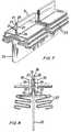
- Figures 3 and 4 and 7 and 8show the steps in the formation of the side seam seal, the finished filter element being obtained subsequent to application of the end caps.
- the filter element Fcomprises two sheets 1, 2 of nonwoven fibrous filter sheet material, in this case of polypropylene fibers.
- the sheetsare in close juxtaposition, with no spacer therebetween, and are sandwiched between inner and outer sheats 17, 18 of open polypropylene extruded (nonwoven) netting.
- the two filter sheetscan be of the same porosity, it is generally preferred that the upstream filter sheet be coarser than the downstream filter sheet.
- the outer upstream sheet 1has an average pore size of approximately 15 microns
- the inner downstream filter sheet 2has an average pore size of approximately 2 microns.
- the two sheets, 1, 2 2 of filter material and two sheets 17, 18 of sheath netting after being superimposed in juxtapositionare corrugated in a plurality of corrugations 3, and the ends of the sheets folded over and brought together into a cylinder 4 of the desired length and diameter.
- the side seam sealis formed by inserting a T-form support 5 in the last corrugations 6 on each side of the inner sheath 18 before the ends 7, 8 of the inner and outer filter sheets 1, 2, opening out the ends of the last corrugations, as seen in Figure 3, so that the two end portions 7, 8 of the inner and outer sheets are parallel.
- the two end portions 8 of the outer filter sheet 1are separated, to the position shown in Figure 3, while the end portions 7 of the inner sheet 2 remain in abutting relation, and a U-shaped channel strip 11 of polypropylene sheet is inserted over the two ends of the inner layer.
- the spacing apart of the sides 9 of the polypropylene channel stripis slightly greater than the thickness of the two abutting end portions 7 of the inner filter sheet 2.
- the outer surfaces 10 of the two end portions 7 of the inner filter sheet 2are in juxtaposition to the inner surface 12 of the polypropylene strip 11, and the inner surfaces 13 of the two end portions 8 of the outer filter sheet 1 are in juxtaposition to the outer surface 14 of the polypropylene strip 11.
- each of the inner and outer filter layersis now heat-bonded to the polypropylene strip, forming a leak-tight seal.
- the composite seam assembly 16is placed between the heated jaws or platens 15 of a heat-sealing device of conventional type, and heat and pressure applied to the seam, through the outer filter layer 1 to the channel strip 11 and inner filter layer 2, bringing the inner and outer layers into contact under pressure with the polypropylene strip, and all three components, since they are all of polypropylene, are now softened by the application of heat through the platens.
- the filter element 20comprises one sheet 21 of nonwoven fibrous filter sheet material, in this case of polypropylene fibers, sandwiched between inner and outer sheats 17, 18 as in Figures 1 to 4.
- the sheet 21has an average pore size of approximately 5 microns.
- the sheet and sheath compositeis corrugated in a plurality of corrugations 23, and the ends 27, 28 of the composite are folded over and brought together into a cylinder 24 of the desired length and diameter.
- the side seam sealis formed by inserting a T-form support 25 in the last corrugations 26 of the filter sheet material before the ends 27, 28, opening out the ends of the last corrugations 26, as seen in Figure 7, so that the two end portions 27, 28 are parallel.
- a U-shaped channel strip 31 of polypropylene sheetis inserted over the two ends of the filter sheet 21.
- the spacing apart of the sides 29 of the polypropylene channel stripis slightly greater than the thickness of the two abutting end portions 27, 28 of the filter sheet 21. Accordingly, the outer surfaces 30 of the two end portions 27, 28 of the filter sheet 21 are in juxtaposition to the inner surface 32 of the polypropylene channel strip 31.
- the filter sheetis now heat-bonded to the polypropylene channel strip, forming a leak-tight seal.
- the composite seam assembly 36is placed between the heated jaws or platens 35 of a heat-sealing device of conventional type, and heat and pressure applied to form the side seam seal through the channel strip 31 to the filter layer 21, bringing the layer into contact under pressure with the polypropylene strip, and both components, since they are all of polypropylene, are now softened by the application of heat through the platens.
- the pressure applied by the platensforces the molten polypropylene material to penetrate the open pores of the filter sheet, forming a liquid-impervious seal, and when the platens are removed and the polypropylene again solidifies, an integrated one-piece side seam seal is formed with the joint of the filter sheet completely closed off by the U-base of the strip 31.
- the sealitself takes up very little of the surface area of the fitter, in fact, only a portion equal to the width of the channel strip, since the strip extends outwardly from the filter surface. Accordingly, the side seam seal offers a minimum of obstruction of flow of fluid from the exteriorto the interior of the filter cylinder.
- thermoplastic end capwhich is also of polypropylene in the case of the embodiment shown in the drawings, the same material as the bonding strip for the side seam seal, is liquefied to from about 10 to about 90% of the thickness of the end cap to be adhered to the filter cylinder, while cooling the outside face of the thermoplastic end cap to a temperature below its softening point, to maintain the exterior of the end cap in a solid state.
- the liquefied thermoplastic materialpermeates the pores of the ends of the filter material, and when the liquid plastic material has been hardened, the end cap is bonded to the filter with the side seam seal an integral part of the bond. The procedure can then be repeated for capping the other end of the filter element.
- the process of the inventionis applicable to forming tubular filter elements of any configuration.
- a side seam seal and an end cap appropriate to the configuration of the tubular filter elementis of course employed in each case.
- the filter elementsare in cylindrical corrugated form, but the process is also applicable to tubular elements in any cross-sectional configuration, including plain, folded, convoluted and corrugated triangular, square, rectangular, elliptical and other polygonal filter tubes.
- the size and configuration of the convolutions in the case of a corrugated elementare not critical, and any thermoplastic resinous material can be employed for the side seam seal and the end caps.
- the process of the inventionis applicable to tubular filter elements made of from one, two, three, four, five or more layers of the same or different filter materials.
- the tubecan be made so by incorporation of a central core or support, such as a spring or a supporting tube of rigid metallic or plastic material, for instance, a perforated metal or plastic foraminous core or spring of conventional construction.
- External sheath supportscan also be applied. Any internal and/or external support is normally of a length substantially equal to that of the filter element, so that the support and the edges of the filter element are in a substantially flush fit with the can caps, when they are bonded thereto.
- the end capscan be made with appropriate raised or depressed portions and apertures to meet the shape and flow requirements of the ends of the filter support, and the folds are convolutions of the filter tube, and in accordance with the flow requirements and structural requirements of the filter assembly in which the filter element is to be used.
- the process of the inventionis applicable to filter elements made of any porous sheet material having pores extending from surface to surface.
- Two or more layers of the same or varying porositycan be employed in close juxtaposition, or even bonded together, but also spaced apart by suitable spacing sheets.
- Paperwhich can if desired be resin-impregnated (for example, polypropylene), is a preferred filter material.
- the inventionis applicable to papers and like sheet materials formed of any type of fiber including not only cellulose fibers, but also synthetic thermoplastic and nonthermoplastic resin fibers, and fibers of other cellulosederiva- tives, including for example, fibers of polyvinyl chloride, polyethylene, polypropylene, polyvinylidene chloride, polyamide, polyacrylonitrile, polyester, cellulose acetate, cellulose acetate propionate, viscose rayon, cuprammonium rayon, zein and the alginates, glass, asbestos, potassium titanate, mineral wool, rubber, casein, hemp, jute, linen, cotton, silk, wool, and mohair.
- textile fabrics and woven and nonwoven fibrous layers of all kindssuch as felts, mats and bats made of fibrous materials of any of the types listed above.
- the filter sheet material of which the filter elements of the invention are made if desiredcan be impregnated with a synthetic resin or cellulose derivative to increase its strength and resistance to wear by the fluid being filtered.
- the impregnating agentcan be any material useful in the impregnation of papers and textile materials. Such materials are well-known in the paper and textile arts.
- the impregnating agentscan be in liquid form, capable of undergoing solidification as by polymerization, cross-linking, or the like. They can also be in solid form, and applied to the base from a solution in an inert solvent, or as melts.
- Representative impregnating resinsinclude phenol-formaldehyde resins, urea-formaldehyde resins, melamine-formaldehyde resins, polyester resins, and polyepoxide resins.
- Microporous filter elementsmay be defined as having an average pore size of less than about 5 microns and preferably an average pore size of less than about 0.5 micron. There is no effective lower limit on the pore size of the microporous filter, except that imposed by the excessive pressure required to force water to pass through the filter, at an unduly low rate of flow through, and more rapid plugging. It has been found, in practical applications, that microporous filters having an average pore size as low as 0.02 micron and even lower can be end capped in the invention.
- the depth or thickness of the microporous fibrous filteris not critical. A thick filter operates efficiently, but it should not create an undue pressure drop.
- a preferred microporous filteris made of a porous base, such as paper, having relatively large pores, within or on the surface of which is deposited particulate material in an amount to diminish the average diameter thereof to less than 1 micron while retaining a voids volume in the microporous portion in excess of 75%, as disclosed in U.S. patent No. 3 238 056 to Pall et al dated March 1, 1966, and U.S. patent No. 3 246 767 to Pall et al dated April 19, 1966, the disclosures of which are herein incorporated by reference.
- the particulate materialwhich can be in the form, for example, of fibers or fine structured granules, is suspended in a fluid and deposited therefrom upon the surface of the porous base material.
- the particulate materialcan all be of the same size and type, or of two or more sizes and types, all suspended in the fluid system.
- the desired reduction in pore diameter of the baseis obtained by varying the size and amount of the particulate material deposited, blending different sizes at different points, if desired.
- a particularly preferred microporous filteris one of the type described in patent No.
- 3 246 767which comprises a porous base having superimposed thereone and adherent thereto a microporous layer comprising a fibrous material of which a proportion of fibers extend outwardly from the porous base at an angle greater than 30°, the microporous layer having an average pore diameter of less than 1 micron and a voids volume of at least 75%.
- the fiber spacing and angular disposition to the base throughout the entire microporous layeris noted by cross-sectional examination, upon sufficient magnification through an optical or electron microscope. The angular disposition of the fibers is in a large . measure responsible for the high voids volume and low pore size characteristic of the microporous filters.
- the end capscan be of any desired configuration, appropriate to the requirements of the filter tube and filter assembly. Usually. at least one of the end caps will be provided with an aperture for delivery of filtered fluid from or unfiltered fluid to the interior of the structure. In many instances, both end caps will be apertured, particularly where a plurality of filter elements are to be connected together to form a long tube.
- thermoplastic materialsAs is well known is the field of plastics, most thermoplastic materials have a wide range of temperatures over which they can be softened. However, it is only after the thermoplastic material is heated to a temperature above its maximum softening point that the material is liquefied.
- the bonding channel strip(and also the end caps and/or filter sheet material when they are to be made of thermoplastic material) can be made from any thermoplastic resin that is in or can be brought to a liquid state as by heating to above its maximum softening point.
- thermoplastic resinthat is in or can be brought to a liquid state as by heating to above its maximum softening point.
- the thermoplastic material employed in the side seam seal and in the end cappreferably when liquid, has a low viscosity, and preferably less than about 50 cp, to ensure that the resin can penetrate the pores of the filter material and thus form a leak-proof seal.
- the bonding channel strip and end cap thermoplastic resin materialscan be employed alone or with conventional fillers and/or pigments.
- Typical resins which can be employed herein, their softening range, and their liquefaction temperature,are set out in the Table below. It is to be understood that the liquefaction temperature of the resins listed hereinafter varies with the molecular weight of the resins, and that the softening range listed for each resin is for the most common form of the particular resin.
- thermoplastic materialssuch as lignin-sulfonate resins, terpene resins, and the like can be used herein.
- the processis particularly applicable to filter elements in which the U-bonding strip and end caps are made of the same thermoplastic material, which material meets the requirements for end cap and bonding strip materials referred to above.
- the sealis formed between the end cap and side seam seal is exceptionally strong, and all components of the filter element have the same corrosion resistance and resistance to contamination.
- a filter element made entirely of one materialis resistant to attack to the range of reagents of that material and hence is more widely useful than a filter element having two components, the presence of which greatly expands the range of reagents which are capable of attacking the filter element.
- the bonding channel stripcan be of a width overall appropriate to the filter sheet material.
- a rough-surfaced materialwill be wider than a smooth-surfaced material.
- a channel strip of from 0.25 to 5 mm in widthwill be satisfactory.
- the bonding channel stripcan have any cross-sectional configuration, including not only U-shapes with rounded web forming the sides of the channel but also squared-off channel shapes such as and V shapes, and other polygonal shapes.
- thermoplastic or pressure-sensitive channel stripcan be bonded to the juxtaposed sheet surfaces by application of heat and pressure.
- a thermosetting resinsuch as the phenol-formaldehyde, urea-formaldehyde and polyepoxide resins can be used in an incompletely polymerized stage wherein they are still thermoplastic or pressure-sensitive, and converted to a thermoset nonthermoplastic stage of polymerization under the application of heat and pressure so as to make a leak-proof seal that is also permanent.
- the curing of the resin impregnant and of the resin stripcan be effected simultaneously.
- the filter materialalso can be given an oven or like heat treatment after formation of the side seam seal, to complete the cure of any impregnant and of the bonding channel strip.
Landscapes
- Engineering & Computer Science (AREA)
- Mechanical Engineering (AREA)
- Chemical & Material Sciences (AREA)
- Chemical Kinetics & Catalysis (AREA)
- Filtering Materials (AREA)
- Separation Using Semi-Permeable Membranes (AREA)
- Filtration Of Liquid (AREA)
- Filtering Of Dispersed Particles In Gases (AREA)
Description
- Cylindrical filter elements have one or more filter sheets or layers formed in a cylindrical configuration, with the open ends of the cylinder closed off by end caps bonded to the ends of the filter sheets. It is essential that the end caps be bonded securely to all protions of the filter sheets, so as to compel fluid passing between the interior and the exterior of the filter cylinder to proceed by way of the filter sheets. Such cylindrical filter elements can be aranged to accept fluid flow either form the inside out, or from the outside in, but in either case all flow must pass through the filter sheets.
- In the manufacture of cylindrical filter elements with ultrafine removal ratings, generally in the range of 5 microns to 0.2 micron or less, it is frequently advantageous to use very thin filter sheets, since a thin sheet presents less resistance to fluid flow than a thick one. Such sheets tend to be fragile, and it is for this reason desirable to reinforce the thin sheet against rupture due to applied pressure in both directions, and against mechanical damage by handling during and after fabrication, by surrounding it with relatively thicker and stronger layers of more open foraminous sheet materials, such as, for example, tough longfib- ered papers, including hemp and cotton fiber papers.
- In the manufacture of sich cylindrical filter elements from one or more sheets of filter material, it is customary to fold the sheet or sheets into the form of a cylinder, either straight or with corrugations, to increase the useful area of filter sheets within a confined space, and then join the opposite ends of the filter sheets in a side seam. One way of doing this is to bind the the edges together by a metal clip or band, as shown and described in U.S. patent No. 3 127 341, patented March 31, 1964, and in DE-U No. 1924826, published October 7, 1965. No. 1 924 826 indicates that the seam can be sealed by application of an adhesive, but that the application of the U-shaped band is simpler. Neither patentee uses an adhesive when the band is used.
- An alternative, as axemplified by No. 1 924 826, is to bond the side seam with a bonding agent or adhesive strip or coating between the opposed faces. In forming the seal, usually the two outisde surfaces of the ends of the sheet are brought together. One or both of the opposed surfaces is coated with adhesive before the surfaces are brought into contact, and the seal is then formed by application of heat to set the adhesive. A seal is formed in which a layer of adhesive extends from end to end of the seam, and across the seam from the outer surface to the inner surface of the filter sheets, and this layer of adhesive is presented endwise to the filter cap.
- When the filter element is in the ultrafine category as described above, and contains coarser protective layers about the fine filtering layers, it is very difficult in practice to obtain a tight seal throughout the two coarse layers which are interposed between the two fine layers at the side seal. This difficulty arises in part because an adhesive of sufficiently low viscosity to penetrate the coarser layers tends to be rapidly drawn away by the finer capillarity of the fine filter sheets. For this reason, such seals tend to be very unreliable, and permit passage of solids through the filter element by edgewise flow through the two interposed coarser layers at the side seal.
- The adhesive systems used to bond the end caps to the ends of the side sealed pack usually adhere very well to the filter media layers, since these are porous, and consequently absorb some of the adhesive, forming a good bond. The same is not true in relation to the layer of adhesive of which the side seam is composed, and in many systems there is zero adhesion at this point. Consequently, it frequently happens that a poor seal is formed at the adhesive layer, with the result that a leakage path can be formed under fluid pressure across the filter element, since the adhesive extends form the outer surface to the inner surface of the filter across the seam. The result is a potential bypass route for fluid which does not pass through the filter.
- Canadian patent No. 742 053 issued September 6,1966 to David B. Pall and Herbert L. Forman describes a reversed lapped seam side seal, wherein outer surfaces of the adjacent sheet portions are brought together in face-to-face relationship, with a self-sustaining ribbon of bonding agent therebetween bonding the sheet portions together to from a leak-proof seal. However, in this type of seam also the bonding agent extends form end to end of the filter, and from inner surface to outer surface of the filter sheet, and consequently the same bonding problem to the end cap is presented.
- A potential leakage path of this sort cannot be tolerated in cylindrical filter elements in which the filter sheet is of a pore size such that the filter can be used in filtering out yeasts or bacteria. The development of such a leakage path in use under high fluid pressure, even if the fluid pressure be extraordinary and well beyond the normal fluid pressure, will result in organisms bypassing the filter, with possibly disastrous consequences. The result is that for ultrafine filter use, it is not always possible to use cylindrical filter elements, particularly when high internal fluid pressures are apt to be encountered.
- Pall and Jasaitis U.S. patent No. 3867294, patented February 18, 1975, provide a cylindrical filter element comprising one or more layers of filter sheet material formed in a substantially cylindrical shape, and having opposite sheet end portions folded over with outer and inner end surfaces in adjacent relation and joined together in a side seam seal wherein portions of the sheet adjacent the sheet ends have one surface in face-to-face closely-abutting contact, extending to the end edges of the sheet, and the next-adjacent portions have the other surfaces opposite each other, extending beyond the end edges of the end portions of the sheet, and spaced apart by the foldedover abutting sheet ends, the opposed surfaces of the sheet ends and the end edges of the sheet ends defining a space therebetween, with a bonding agent in the space bonding the sheets together ot the end edges and the opposed surfaces of the sheet substantially without penetrating the face-to-face end portions of the sheet at the seam to the outer surface of the filter sheet.
- Thus, the sheet ends are exposed directly to the sealing adhesive, and since the ends of the fine filter sheet layer are similarly exposed, there is no hindrance to the accomplishment of a reliable seal to the ends of the fine filter sheet, and bypassing through the coarser protective layers cannot occur.
- Further, in this side seam seal there is filter sheet material available for bonding to the filter end caps without interference by an end of the bonding agent layer, and although there is al layer of bonding agent at the end cap, it does not extend from the inner surface to the outer surface of the filter sheet material. Consequently, no potential leakage path exists at the end cap, due to the bonding agent holding the side seam seal together.
- As the bonding agent, a self-sustaining ribbon of bonding agent can be used, of a thickness chosen to just fill the space between the ends of the filter sheet and the opposed next-adjacent surfaces. Application of heat through conventional means causes the ribbon to soften and melt, and produces a leak-proof bond throughout this space. The ribbon can be the type of resin which solidifies on cooling (»hot melt« adhesive) or it can be of the type which polymerizes on heating, but in either event it must reach a low enough viscosity for a sufficient time to penetrate slightly into the filter medium. As an alternate, a material which solidifies by polymerizing can be applied as a liquid. In either case, the temporary application of a strip of pressure-sensitive tape across each end prevents the molten material from running out, and causes it to harden neatly flush with the ends of the cylinder. The use of a self-sustaining ribbon instead of a coating makes it pissible to obtain uniforms thickness and with of the bonding agent throught this space, so that the bonding agent layer is absolutely uniform form end to end the filter cylinder.
- While this side seam seal has proved effective, it is costly to introduce in cylindrical filter elements, because of the number of hand operations that be performed. Consequently, it cannot be used for cylindrical filter elements that must be marketed at a low cost.
- In accordance with the instant invention, a tubular corrugated filter element is provided comprising at least one layer of filter sheet material formed in a substantial tubular shape and having the side seam edges of the filter sheet in adjacent relation, and joined together in a side seam seal by way of a self-supporting bonding channel strip of the thermoplastic resinous material embracing said edges of the filtersheet, the channel strip being bonded to the filter sheet, thereby sealing said edges of the sheet together in a liquid light seal.
- In a preferred embodiment the tubular corrugated filter element comprises two layers of filter sheet material formed in a substantially tubular shape and having the inner surface of the side seam edges of the outer filter sheet and the outer surface of the side seam portions of the inner filter sheet in adjacent relation, and joined together in a side seam seal by way of an interposed self-supporting bonding channel strip of thermoplastic resonous material embracing said outer edges of the inner filter sheet, the channel strip being bonded to the inner and outer filter sheets, the reby sealing the edges of the two sheets together in a leak-tight seal, and blocking the escape of unfiltered liquid between said edges of the inner filter sheet of the tubular filter element.
- In all embodiments, the side seam edges of the filter sheet or sheets in the filter element are joined together and embraced by a nonporous bonding strip formed in a channel configuration, blocking the escape of unfiltered liquid between said edges of the filter sheet or sheets of the filter element.
- Further, since the bonding channel strip in this side seam seal is of thermoplasitc resinous material, it can be the same plastic material as the end caps and/or of the filter sheets. This makes it possible to integrate the bonding channel strip material with the end cap and side seam seal and/or filter sheet material, forming an integral one-piece filter element. The side seam seal can be formed before bonding of the filter end caps to the open ends of the cylindrica! filter element; since the materials are the same, there is no interference by an end of a bonding agent layer with this seal. Consequently, no potential leakage path can exist st the end cap, due to the bonding agent holding the side seam seal together, since the bonding agent holding the side seam seal together, since the bonding agent in the points where it contats the end cap materials is integrated with the end cap material, forming one unit.
- As the bonding channel strip, any self-sustaining channel strip of the thermoplastic resonous material, preferably the same thermoplastic material as the end cap material, can be used. Application of heat through conventional means causes the thermoplastic channel strip material to soften and melt, and enter the pores of the filter sheet or sheets with which it is in contact, and produce a leak-tight bond throughout the contact area.
- The bonding channel strip can be of the type of resin which solidifies on cooling (hot-melt thermoplastic materials), or it can be of the type which polymerizes on heating, and thereafter becomes nonthermoplastic, although thermoplastic in the initial stage of polymerization at which stage the bond is formed. In either event, the channel strip when molten or softened must reach a low enough viscosity for a sufficient time to penetrate at least slightly into the abutting sheets of filter medium.
- The use of a self-sustaining channel strip instead of a coating makes it possible to obtain uniform thickness and width of the bonding strip throughout the seal, so that the seal is absolutely uniform in thickness form end to end of the filter cylinder.
- The invention is illustrated in the accompanying drawings, in which:
- Figure 1 shows in cross-section a filter element in cylindrical corrugated form, having two filter layers bonded together at their side seam edges with a channel strip as the side seam seal in accordance with the invention;
- Figure 2 is a perspective detailed end view of the channel strip side seam seal of the filter element of Figure 1;
- Figure 3 shows the filter composite in an initial preparatory stage, just prior to forming the side-seam seal, with the bonding channel strip sandwiched between the inner and outer filter layers of the filter element, after spreading apart the ends of the two layers, and inserting the channel strip;
- Figure 4 shows the side seam seal being formed in the assembly of Figure 3 by application of heating platens to the outer pheriphery of the outer filter layer at the side seam seal on each side, the finished filter element after application of end caps being that shown in Figures 1 and 2;
- Figure 5 shows in cross-section a filter element in cylindrical corrugated form, having one filter layer bonded at its side seam edges with a channel strip as the side seam seal in accordance with the invention;
- Figure 6 is a perspective detailed end view of the channel strip side seam seal of the filter element of Figure 5;
- Figure 7 shows the filter composite in an initial preparatory stage, just prior to forming the side-seam seal, with the bonding channel strip embracing between the outer surface of the ends of the filter layer of the filter element; and
- Figure 8 shows the side seam seal being formed in the assembly of Figure 7 by application of heating platens to the outer surface of the channel strip, the finishing filter element after application of end caps being that shown in Figures 5 and 6.
- The filter elements in accordance with the invention are readily prepared from one or more sheets of filter sheet material by placing the two sheets in close juxtaposition, and corrugating and forming the filter sheet material in the usual way. The only difference in fact from the usual process of manufacture is in the formation of the side seam seal. Figures 3 and 4 and 7 and 8 show the steps in the formation of the side seam seal, the finished filter element being obtained subsequent to application of the end caps.
- In the dual layer embodiment of the filter element of the invention, as seen in Figures 1 to 4, the filter element F comprises two
sheets 1, 2 of nonwoven fibrous filter sheet material, in this case of polypropylene fibers. The sheets are in close juxtaposition, with no spacer therebetween, and are sandwiched between inner andouter sheats downstream filter sheet 2 has an average pore size of approximately 2 microns. The two sheets, 1, 2 2 of filter material and twosheets corrugations 3, and the ends of the sheets folded over and brought together into a cylinder 4 of the desired length and diameter. - The side seam seal is formed by inserting a T-
form support 5 in thelast corrugations 6 on each side of theinner sheath 18 before the ends 7, 8 of the inner andouter filter sheets 1, 2, opening out the ends of the last corrugations, as seen in Figure 3, so that the twoend portions 7, 8 of the inner and outer sheets are parallel. The twoend portions 8 of the outer filter sheet 1 are separated, to the position shown in Figure 3, while the end portions 7 of theinner sheet 2 remain in abutting relation, and a U-shaped channel strip 11 of polypropylene sheet is inserted over the two ends of the inner layer. The spacing apart of thesides 9 of the polypropylene channel strip is slightly greater than the thickness of the two abutting end portions 7 of theinner filter sheet 2. Accordingly, the outer surfaces 10 of the two end portions 7 of theinner filter sheet 2 are in juxtaposition to theinner surface 12 of the polypropylene strip 11, and the inner surfaces 13 of the twoend portions 8 of the outer filter sheet 1 are in juxtaposition to the outer surface 14 of the polypropylene strip 11. - It is apparent from Figures 2 and 3 that the polypropylene strip extends from end to end of the filter element.
- Each of the inner and outer filter layers is now heat-bonded to the polypropylene strip, forming a leak-tight seal. As seen in Figure 4, the composite seam assembly 16 is placed between the heated jaws or
platens 15 of a heat-sealing device of conventional type, and heat and pressure applied to the seam, through the outer filter layer 1 to the channel strip 11 andinner filter layer 2, bringing the inner and outer layers into contact under pressure with the polypropylene strip, and all three components, since they are all of polypropylene, are now softened by the application of heat through the platens. The pressure applied by the platens forces the molten polypropylene material to penetrate the open pores of the filter sheets, forming a liquid-impervious seal, and when the platens are removed and the polypropylene again solidifies, an integrated one-piece side seam seal is formed with the joint of the inner filter layers completely closed off by the base of the channel strip 11. - In the single-layer filter element of the invention, as seen in Figures 5 to 8, the
filter element 20 comprises onesheet 21 of nonwoven fibrous filter sheet material, in this case of polypropylene fibers, sandwiched between inner andouter sheats sheet 21 has an average pore size of approximately 5 microns. The sheet and sheath composite is corrugated in a plurality ofcorrugations 23, and theends cylinder 24 of the desired length and diameter. - The side seam seal is formed by inserting a T-
form support 25 in thelast corrugations 26 of the filter sheet material before the ends 27, 28, opening out the ends of thelast corrugations 26, as seen in Figure 7, so that the twoend portions U-shaped channel strip 31 of polypropylene sheet is inserted over the two ends of thefilter sheet 21. The spacing apart of thesides 29 of the polypropylene channel strip is slightly greater than the thickness of the twoabutting end portions filter sheet 21. Accordingly, theouter surfaces 30 of the twoend portions filter sheet 21 are in juxtaposition to theinner surface 32 of thepolypropylene channel strip 31. - It is apparent form Figures 6 and 7 that the polypropylene channel strip extends axially from end to end of the filter element.
- The filter sheet is now heat-bonded to the polypropylene channel strip, forming a leak-tight seal. As seen in Figure 8, the
composite seam assembly 36 is placed between the heated jaws orplatens 35 of a heat-sealing device of conventional type, and heat and pressure applied to form the side seam seal through thechannel strip 31 to thefilter layer 21, bringing the layer into contact under pressure with the polypropylene strip, and both components, since they are all of polypropylene, are now softened by the application of heat through the platens. The pressure applied by the platens forces the molten polypropylene material to penetrate the open pores of the filter sheet, forming a liquid-impervious seal, and when the platens are removed and the polypropylene again solidifies, an integrated one-piece side seam seal is formed with the joint of the filter sheet completely closed off by the U-base of thestrip 31. - It is apparent from the drawing that in this of side seam seal, the seal itself takes up very little of the surface area of the fitter, in fact, only a portion equal to the width of the channel strip, since the strip extends outwardly from the filter surface. Accordingly, the side seam seal offers a minimum of obstruction of flow of fluid from the exteriorto the interior of the filter cylinder.
- After completion of the side seal, the
internal core 37 is slipped into the open center of the tube, and the end caps 38, 39 are applied, employing the method of U.S. patent No. 3 457 339 to Pall and Jasaitis, patented July 22, 1969. An inside face of the thermoplastic end cap, which is also of polypropylene in the case of the embodiment shown in the drawings, the same material as the bonding strip for the side seam seal, is liquefied to from about 10 to about 90% of the thickness of the end cap to be adhered to the filter cylinder, while cooling the outside face of the thermoplastic end cap to a temperature below its softening point, to maintain the exterior of the end cap in a solid state. All of the edges of one end of the filter material and side seam seal are then embedded in the liquefied face of the end cap, forming a leak-proof seal therewith, and since the plastic material of the side seam seal and filter sheet is the same as the plastic material of the end cap, an integrated unitary filter element structure is formed, upon hardening of the thermoplastic material. - The liquefied thermoplastic material permeates the pores of the ends of the filter material, and when the liquid plastic material has been hardened, the end cap is bonded to the filter with the side seam seal an integral part of the bond. The procedure can then be repeated for capping the other end of the filter element.
- The process of the invention is applicable to forming tubular filter elements of any configuration. A side seam seal and an end cap appropriate to the configuration of the tubular filter element is of course employed in each case. Normally, the filter elements are in cylindrical corrugated form, but the process is also applicable to tubular elements in any cross-sectional configuration, including plain, folded, convoluted and corrugated triangular, square, rectangular, elliptical and other polygonal filter tubes. The size and configuration of the convolutions in the case of a corrugated element are not critical, and any thermoplastic resinous material can be employed for the side seam seal and the end caps.
- The process of the invention is applicable to tubular filter elements made of from one, two, three, four, five or more layers of the same or different filter materials. If the material has insufficient rigidity to be self-supporting, the tube can be made so by incorporation of a central core or support, such as a spring or a supporting tube of rigid metallic or plastic material, for instance, a perforated metal or plastic foraminous core or spring of conventional construction. External sheath supports can also be applied. Any internal and/or external support is normally of a length substantially equal to that of the filter element, so that the support and the edges of the filter element are in a substantially flush fit with the can caps, when they are bonded thereto. The end caps can be made with appropriate raised or depressed portions and apertures to meet the shape and flow requirements of the ends of the filter support, and the folds are convolutions of the filter tube, and in accordance with the flow requirements and structural requirements of the filter assembly in which the filter element is to be used.
- Thus, the process of the invention is applicable to filter elements made of any porous sheet material having pores extending from surface to surface. Two or more layers of the same or varying porosity can be employed in close juxtaposition, or even bonded together, but also spaced apart by suitable spacing sheets. Paper, which can if desired be resin-impregnated (for example, polypropylene), is a preferred filter material. The invention is applicable to papers and like sheet materials formed of any type of fiber including not only cellulose fibers, but also synthetic thermoplastic and nonthermoplastic resin fibers, and fibers of other cellulosederiva- tives, including for example, fibers of polyvinyl chloride, polyethylene, polypropylene, polyvinylidene chloride, polyamide, polyacrylonitrile, polyester, cellulose acetate, cellulose acetate propionate, viscose rayon, cuprammonium rayon, zein and the alginates, glass, asbestos, potassium titanate, mineral wool, rubber, casein, hemp, jute, linen, cotton, silk, wool, and mohair. Also useful, in addition to papers, are textile fabrics and woven and nonwoven fibrous layers of all kinds, such as felts, mats and bats made of fibrous materials of any of the types listed above.
- The filter sheet material of which the filter elements of the invention are made if desired can be impregnated with a synthetic resin or cellulose derivative to increase its strength and resistance to wear by the fluid being filtered. The impregnating agent can be any material useful in the impregnation of papers and textile materials. Such materials are well-known in the paper and textile arts. The impregnating agents can be in liquid form, capable of undergoing solidification as by polymerization, cross-linking, or the like. They can also be in solid form, and applied to the base from a solution in an inert solvent, or as melts. Representative impregnating resins include phenol-formaldehyde resins, urea-formaldehyde resins, melamine-formaldehyde resins, polyester resins, and polyepoxide resins.
- The process of the invention is particularly applicable to.microporous filter elements. Microporous filter elements may be defined as having an average pore size of less than about 5 microns and preferably an average pore size of less than about 0.5 micron. There is no effective lower limit on the pore size of the microporous filter, except that imposed by the excessive pressure required to force water to pass through the filter, at an unduly low rate of flow through, and more rapid plugging. It has been found, in practical applications, that microporous filters having an average pore size as low as 0.02 micron and even lower can be end capped in the invention.
- The depth or thickness of the microporous fibrous filter is not critical. A thick filter operates efficiently, but it should not create an undue pressure drop.
- A preferred microporous filter is made of a porous base, such as paper, having relatively large pores, within or on the surface of which is deposited particulate material in an amount to diminish the average diameter thereof to less than 1 micron while retaining a voids volume in the microporous portion in excess of 75%, as disclosed in U.S. patent No. 3 238 056 to Pall et al dated March 1, 1966, and U.S. patent No. 3 246 767 to Pall et al dated April 19, 1966, the disclosures of which are herein incorporated by reference. The particulate material, which can be in the form, for example, of fibers or fine structured granules, is suspended in a fluid and deposited therefrom upon the surface of the porous base material. The particulate material can all be of the same size and type, or of two or more sizes and types, all suspended in the fluid system. The desired reduction in pore diameter of the base is obtained by varying the size and amount of the particulate material deposited, blending different sizes at different points, if desired. A particularly preferred microporous filter is one of the type described in patent No. 3 246 767 which comprises a porous base having superimposed thereone and adherent thereto a microporous layer comprising a fibrous material of which a proportion of fibers extend outwardly from the porous base at an angle greater than 30°, the microporous layer having an average pore diameter of less than 1 micron and a voids volume of at least 75%. The fiber spacing and angular disposition to the base throughout the entire microporous layer is noted by cross-sectional examination, upon sufficient magnification through an optical or electron microscope. The angular disposition of the fibers is in a large . measure responsible for the high voids volume and low pore size characteristic of the microporous filters.
- The end caps can be of any desired configuration, appropriate to the requirements of the filter tube and filter assembly. Usually. at least one of the end caps will be provided with an aperture for delivery of filtered fluid from or unfiltered fluid to the interior of the structure. In many instances, both end caps will be apertured, particularly where a plurality of filter elements are to be connected together to form a long tube.
- As is well known is the field of plastics, most thermoplastic materials have a wide range of temperatures over which they can be softened. However, it is only after the thermoplastic material is heated to a temperature above its maximum softening point that the material is liquefied.
- Accordingly, the bonding channel strip (and also the end caps and/or filter sheet material when they are to be made of thermoplastic material) can be made from any thermoplastic resin that is in or can be brought to a liquid state as by heating to above its maximum softening point. If an ultrafine filter material, i. e., filter material having an average pore size below about 5 microns, is employed, the thermoplastic material employed in the side seam seal and in the end cap, preferably when liquid, has a low viscosity, and preferably less than about 50 cp, to ensure that the resin can penetrate the pores of the filter material and thus form a leak-proof seal.
- The bonding channel strip and end cap thermoplastic resin materials can be employed alone or with conventional fillers and/or pigments. Typical resins which can be employed herein, their softening range, and their liquefaction temperature, are set out in the Table below. It is to be understood that the liquefaction temperature of the resins listed hereinafter varies with the molecular weight of the resins, and that the softening range listed for each resin is for the most common form of the particular resin.

- In addition to the above materials, other thermoplastic materials such as lignin-sulfonate resins, terpene resins, and the like can be used herein. The term »thermoplastic« ist accordingly used herein to refer both to thermoplastic resins and to resins in a liquid or thermoplastic stage of polymerization further polymerizable to a solid polymer.
- As previously indicated, the process is particularly applicable to filter elements in which the U-bonding strip and end caps are made of the same thermoplastic material, which material meets the requirements for end cap and bonding strip materials referred to above. When these components are of the same material, the seal is formed between the end cap and side seam seal is exceptionally strong, and all components of the filter element have the same corrosion resistance and resistance to contamination. A filter element made entirely of one material is resistant to attack to the range of reagents of that material and hence is more widely useful than a filter element having two components, the presence of which greatly expands the range of reagents which are capable of attacking the filter element.
- The bonding channel strip can be of a width overall appropriate to the filter sheet material. A rough-surfaced material will be wider than a smooth-surfaced material. Usually, a channel strip of from 0.25 to 5 mm in width will be satisfactory.
- The bonding channel strip can have any cross-sectional configuration, including not only U-shapes with rounded web forming the sides of the channel but also squared-off channel shapes such as and V shapes, and other polygonal shapes.
- A thermoplastic or pressure-sensitive channel strip can be bonded to the juxtaposed sheet surfaces by application of heat and pressure. A thermosetting resin such as the phenol-formaldehyde, urea-formaldehyde and polyepoxide resins can be used in an incompletely polymerized stage wherein they are still thermoplastic or pressure-sensitive, and converted to a thermoset nonthermoplastic stage of polymerization under the application of heat and pressure so as to make a leak-proof seal that is also permanent.
- In the case in which the sheet filter material is impregnated with an impregnating resin for greater strength, and the resin is in an incomplete stage of polymerization, the curing of the resin impregnant and of the resin strip can be effected simultaneously. The filter material also can be given an oven or like heat treatment after formation of the side seam seal, to complete the cure of any impregnant and of the bonding channel strip.

Claims (10)
Applications Claiming Priority (2)
| Application Number | Priority Date | Filing Date | Title |
|---|---|---|---|
| US05/837,663US4184966A (en) | 1977-09-29 | 1977-09-29 | Tubular filter elements with improved side seam seal |
| US837663 | 1977-09-29 |
Publications (2)
| Publication Number | Publication Date |
|---|---|
| EP0001407A1 EP0001407A1 (en) | 1979-04-18 |
| EP0001407B1true EP0001407B1 (en) | 1981-02-25 |
Family
ID=25275083
Family Applications (1)
| Application Number | Title | Priority Date | Filing Date |
|---|---|---|---|
| EP78100892AExpiredEP0001407B1 (en) | 1977-09-29 | 1978-09-14 | Tubular filter elements with improved side seam seal |
Country Status (12)
| Country | Link |
|---|---|
| US (1) | US4184966A (en) |
| EP (1) | EP0001407B1 (en) |
| JP (1) | JPS5458269A (en) |
| AU (1) | AU518466B2 (en) |
| CA (1) | CA1099647A (en) |
| DE (1) | DE2860507D1 (en) |
| DK (1) | DK152891C (en) |
| ES (1) | ES245382Y (en) |
| FI (1) | FI66759C (en) |
| IT (1) | IT1106078B (en) |
| NO (1) | NO150587C (en) |
| ZA (1) | ZA785220B (en) |
Cited By (18)
| Publication number | Priority date | Publication date | Assignee | Title |
|---|---|---|---|---|
| FR2509628A1 (en)* | 1981-07-18 | 1983-01-21 | Sartorius Gmbh | TUBULAR FILTER ELEMENT FOR THE FILTRATION OF FLUIDS, AND METHOD FOR PRODUCING THE SAME |
| EP0062867A3 (en)* | 1981-04-14 | 1983-05-11 | Pall Corporation | Polymer filter cartridge of glass fibers coated with fluoroethylene polymer and process for preparing the same |
| WO1987003820A1 (en)* | 1985-12-23 | 1987-07-02 | Caterpillar Inc. | Machine and method for assembling pleated filter material and a hollow core member |
| EP0257794A1 (en)* | 1986-07-25 | 1988-03-02 | Pall Corporation | Filter element |
| EP0173696A4 (en)* | 1984-02-13 | 1988-04-27 | American Filtrona Corp | Pleated filter and method and apparatus for fabricating same. |
| GB2240051A (en)* | 1990-01-18 | 1991-07-24 | Pall Corp | Tubular filter elements |
| GB2247849A (en)* | 1990-09-11 | 1992-03-18 | Pall Corp | Filter element |
| EP0470485A3 (en)* | 1990-07-30 | 1992-04-15 | Pall Corporation | A filter |
| GB2274604A (en)* | 1990-07-30 | 1994-08-03 | Pall Corp | Filter element |
| DE4312705A1 (en)* | 1993-04-20 | 1994-10-27 | Hydac Filtertechnik Gmbh | Filter element with expanded metal jacket |
| US5622537A (en)* | 1990-10-19 | 1997-04-22 | Donaldson Company, Inc. | Filtration arrangement |
| US5669949A (en)* | 1995-04-21 | 1997-09-23 | Donaldson Company, Inc. | Air filtration arrangement |
| US5858044A (en) | 1996-07-11 | 1999-01-12 | Donaldson Company, Inc. | Filter arrangement including removable filter with first and second media secured together |
| USD404807S (en) | 1996-07-11 | 1999-01-26 | Donaldson Company, Inc. | Filter sleeve |
| USD407808S (en) | 1996-07-11 | 1999-04-06 | Donaldson Company, Inc. | Filter element having circular sleeve |
| US6007608A (en) | 1998-07-10 | 1999-12-28 | Donaldson Company, Inc. | Mist collector and method |
| WO2001005483A1 (en)* | 1999-07-20 | 2001-01-25 | Hydac Filtertechnik Gmbh | Filter element comprising an embossed weld connection clip and device for producing the same |
| DE102014010175A1 (en) | 2014-07-09 | 2016-01-14 | Hydac Filtertechnik Gmbh | filter element |
Families Citing this family (43)
| Publication number | Priority date | Publication date | Assignee | Title |
|---|---|---|---|---|
| US4386948A (en)* | 1979-12-20 | 1983-06-07 | American Hospital Supply Corporation | Filter drive |
| US4384474A (en)* | 1980-10-30 | 1983-05-24 | Amf Incorporated | Method and apparatus for testing and using membrane filters in an on site of use housing |
| US4392872A (en)* | 1981-04-03 | 1983-07-12 | Monterey Manufacturing, Inc. | Air bleeder valve for waterbed mattresses |
| JPS5982516U (en)* | 1982-11-24 | 1984-06-04 | 株式会社土屋製作所 | Filtration element for chemical filters |
| EP0187358A3 (en)* | 1984-12-24 | 1987-03-18 | Kurashiki Boseki Kabushiki Kaisha | Filter element and its production |
| JPS6249922A (en)* | 1985-08-28 | 1987-03-04 | Kurabo Ind Ltd | Multilayer filter element |
| JPS62155912A (en)* | 1985-12-28 | 1987-07-10 | Toyo Roshi Kk | Filter element for precision filtration |
| US4735720A (en)* | 1986-03-17 | 1988-04-05 | Nelson Industries Inc. | Pleated filter element having improved side seam seal |
| US5024870A (en)* | 1987-02-19 | 1991-06-18 | Donaldson Company, Inc. | Method for potting pleated filter media and filters made thereby |
| DE4039289A1 (en)* | 1990-12-08 | 1992-06-11 | Knecht Filterwerke Gmbh | Annular filter element for rapid filtration - comprises ends joined by thermoplastic adhesive for sealing filter material folded in zigzag pattern, for easy automation |
| US20020141910A1 (en)* | 1992-01-07 | 2002-10-03 | Adiletta Joseph G. | Regenerable diesel exhaust filter |
| US5250179A (en)* | 1992-03-27 | 1993-10-05 | Porous Media Corporation | Compactable filter and compactable filter mounting means |
| US5435957A (en)* | 1993-09-03 | 1995-07-25 | Pall Corporation | Method of preparing a support material for use with a filtration medium |
| US5632791A (en)* | 1994-12-06 | 1997-05-27 | Bha Group, Inc. | Unitary filter cartridge |
| USRE37163E1 (en)* | 1994-05-06 | 2001-05-08 | Bha Group Holdings, Inc. | Unitary filter cartridge |
| US6726735B1 (en) | 1994-05-06 | 2004-04-27 | Bha Group Holdings, Inc. | Unitary filter cartridge |
| US5653831A (en)* | 1995-10-17 | 1997-08-05 | Sta-Rite Industries, Inc. | Method and apparatus for making a filter module |
| US6099729A (en)* | 1996-03-01 | 2000-08-08 | Parker-Hannifin Corporation | Coreless non-metallic filter element |
| US5762796A (en)* | 1996-03-15 | 1998-06-09 | Parker-Hannifin Corporation | Color coded side seam label for filter element |
| US5873920A (en)* | 1996-09-27 | 1999-02-23 | Dana Corporation | Low restriction, high performance air filter |
| AU4717499A (en)* | 1998-06-26 | 2000-01-17 | Pall Corporation | Internal combustion engine exhaust filters |
| US6932850B1 (en)* | 1998-06-29 | 2005-08-23 | Pall Corporation | Pleated filter and a method for making the same |
| RU2135259C1 (en)* | 1998-10-19 | 1999-08-27 | Научно-производственное предприятие "Технофильтр" | Method of manufacturing cartridge-type corrugated diaphragm filtering element |
| WO2000040319A1 (en)* | 1999-01-07 | 2000-07-13 | Cuno, Incorporated | Pleated filter element and method of forming a pleated filter element |
| US7252011B2 (en)* | 2002-03-11 | 2007-08-07 | Mks Instruments, Inc. | Surface area deposition trap |
| US7473360B2 (en)* | 2002-03-26 | 2009-01-06 | Pall Corporation | Length-adjustable filter cartridge end caps, filter cartridges employing, and methods of making, the same |
| DE10235275A1 (en)* | 2002-08-02 | 2004-02-19 | Hydac Filtertechnik Gmbh | Filter element, for filtering hydraulic oil in hydraulic devices, has arrangement acting on connecting site in filter element to prevent bulging of filter folds in region of connecting site |
| RU2272710C1 (en)* | 2004-07-14 | 2006-03-27 | Ильдус Мухаметгалеевич Закиров | Method of manufacture of the filtering element and the device for its realization |
| DE102004055845B4 (en)* | 2004-11-19 | 2006-08-24 | Zander Aufbereitungstechnik Gmbh & Co. Kg | Hollow-cylindrical filter element for liquid or gaseous media |
| JP2006205133A (en)* | 2005-01-31 | 2006-08-10 | Toyo Roki Mfg Co Ltd | Filter element |
| US7294163B1 (en) | 2005-03-21 | 2007-11-13 | Lacroix Paul E | Cartridge filter |
| US7712483B2 (en)* | 2006-01-24 | 2010-05-11 | Robertshaw Controls Company | Adjustable seat valve with debris trap |
| DE102007006081A1 (en)* | 2007-02-02 | 2008-08-07 | Mann + Hummel Gmbh | Process for producing a pleated filter |
| US20080245726A1 (en)* | 2007-04-05 | 2008-10-09 | Senetar Michael J | Closed-Loop-Bonded Filter Media and Liner Pleat Block and Method |
| DE102007032982B4 (en)* | 2007-07-16 | 2023-03-30 | Emcon Technologies Germany (Augsburg) Gmbh | Exhaust gas treatment device for an exhaust system and method for manufacturing an exhaust gas treatment device |
| DE102009025392A1 (en)* | 2009-06-16 | 2010-12-23 | Mann + Hummel Gmbh | Connecting element for multilayer media, filter element and method for connecting flat media |
| DE102009050257A1 (en) | 2009-10-21 | 2011-05-12 | Mann + Hummel Gmbh | Filter element, filter device and method for producing a filter element |
| DE102009052123A1 (en)* | 2009-11-05 | 2011-05-12 | Mann + Hummel Gmbh | Filter element, filter device and method for producing a filter element |
| KR20120025112A (en)* | 2010-09-07 | 2012-03-15 | 웅진코웨이주식회사 | Filter cartridge |
| TWD149077S (en)* | 2010-11-16 | 2012-09-01 | 旭化成化學股份有限公司 | Hollow fiber membrane for filter |
| US20150096933A1 (en)* | 2013-10-07 | 2015-04-09 | W. L. Gore & Associates, Inc. | Filtration Article Having Thermoplastic Filled Edges |
| USD844103S1 (en)* | 2017-01-18 | 2019-03-26 | Yoshida Tekko Kabushiki Kaisha | Filtration drum |
| TWI699233B (en)* | 2019-09-12 | 2020-07-21 | 濾能股份有限公司 | A cylindric filter device, a manufacturing method and an usage of the same, and a filter system having the same |
Family Cites Families (16)
| Publication number | Priority date | Publication date | Assignee | Title |
|---|---|---|---|---|
| DE1074009B (en)* | 1960-01-28 | |||
| US3127341A (en)* | 1964-03-31 | abeles | ||
| US3038205A (en)* | 1957-10-01 | 1962-06-12 | Walter A Plummer | Plastic tubing |
| US3116245A (en)* | 1958-07-23 | 1963-12-31 | Walker Mfg Co | Filter |
| AT222873B (en)* | 1958-09-04 | 1962-08-10 | Reifenhaeuser Kg | Method and device for the continuous production of a smooth, dimensionally stable tube made of paper or the like. |
| DE1878823U (en)* | 1962-04-25 | 1963-09-05 | Braunschweigische Maschb Ansta | SCREEN COVER, IN PARTICULAR FOR PRE-SURFACE FILTER CANDLES IN THE SUGAR INDUSTRY. |
| FR1403833A (en)* | 1964-05-14 | 1965-06-25 | Herfilco | pleated filter elements |
| CH453934A (en)* | 1965-02-12 | 1968-06-14 | Rheinische Blattmetallgesellsc | Method for producing a sausage-like package |
| US3417551A (en)* | 1965-11-16 | 1968-12-24 | Ford Motor Co | Air filter |
| US3468420A (en)* | 1966-08-17 | 1969-09-23 | Parker Hannifin Corp | Fluid filter |
| DE1972513U (en)* | 1967-06-07 | 1967-11-16 | Ferch & Nabben | TWO-PIECE FILTER HOUSING. |
| US3469707A (en)* | 1967-10-06 | 1969-09-30 | Wix Corp | Filter structure |
| US3591010A (en)* | 1968-06-10 | 1971-07-06 | Pall Corp | Filter having a microporous layer attached thereto |
| FR2214586B1 (en)* | 1973-01-22 | 1977-02-04 | Flax V | |
| US3867294A (en)* | 1973-05-09 | 1975-02-18 | Pall Corp | Cylindrical filter elements with improved side seam seal |
| US3865919A (en)* | 1974-04-19 | 1975-02-11 | David B Pall | Cylindrical filter elements with improved side seam seal |
- 1977
- 1977-09-29USUS05/837,663patent/US4184966A/ennot_activeExpired - Lifetime
- 1978
- 1978-09-14ZAZA00785220Apatent/ZA785220B/enunknown
- 1978-09-14EPEP78100892Apatent/EP0001407B1/ennot_activeExpired
- 1978-09-14DEDE7878100892Tpatent/DE2860507D1/ennot_activeExpired
- 1978-09-27CACA312,176Apatent/CA1099647A/ennot_activeExpired
- 1978-09-27NONO783270Apatent/NO150587C/enunknown
- 1978-09-27JPJP11904178Apatent/JPS5458269A/enactiveGranted
- 1978-09-28FIFI782953Apatent/FI66759C/ennot_activeIP Right Cessation
- 1978-09-28AUAU40269/78Apatent/AU518466B2/ennot_activeExpired
- 1978-09-28DKDK429978Apatent/DK152891C/enactive
- 1978-09-28ITIT51295/78Apatent/IT1106078B/enactive
- 1978-09-28ESES1978245382Upatent/ES245382Y/ennot_activeExpired
Cited By (40)
| Publication number | Priority date | Publication date | Assignee | Title |
|---|---|---|---|---|
| EP0062867A3 (en)* | 1981-04-14 | 1983-05-11 | Pall Corporation | Polymer filter cartridge of glass fibers coated with fluoroethylene polymer and process for preparing the same |
| FR2509628A1 (en)* | 1981-07-18 | 1983-01-21 | Sartorius Gmbh | TUBULAR FILTER ELEMENT FOR THE FILTRATION OF FLUIDS, AND METHOD FOR PRODUCING THE SAME |
| EP0173696A4 (en)* | 1984-02-13 | 1988-04-27 | American Filtrona Corp | Pleated filter and method and apparatus for fabricating same. |
| WO1987003820A1 (en)* | 1985-12-23 | 1987-07-02 | Caterpillar Inc. | Machine and method for assembling pleated filter material and a hollow core member |
| AU573719B2 (en)* | 1985-12-23 | 1988-06-16 | Caterpillar Inc. | Machine and method for assembling pleated filter material and a hollow core member |
| EP0257794A1 (en)* | 1986-07-25 | 1988-03-02 | Pall Corporation | Filter element |
| US4826597A (en)* | 1986-07-25 | 1989-05-02 | Pall Corporation | Filter assembly with removable sheet |
| US5252207A (en)* | 1988-06-15 | 1993-10-12 | Pall Corporation | Wrap member having openings |
| EP0440352A3 (en)* | 1990-01-18 | 1991-09-04 | Pall Corporation | Cylindrical filters and their manufacture |
| US5863432A (en)* | 1990-01-18 | 1999-01-26 | Pall Corporation | Cylindrical filters |
| GB2240051B (en)* | 1990-01-18 | 1993-04-14 | Pall Corp | Cylindrical filters and their manufacture |
| US5593529A (en)* | 1990-01-18 | 1997-01-14 | Pall Corporation | Cylindrical filters and their manufacture |
| GB2240051A (en)* | 1990-01-18 | 1991-07-24 | Pall Corp | Tubular filter elements |
| US5360650A (en)* | 1990-01-18 | 1994-11-01 | Pall Corporation | Cylindrical filters and their manufacture |
| EP0470485A3 (en)* | 1990-07-30 | 1992-04-15 | Pall Corporation | A filter |
| GB2274603B (en)* | 1990-07-30 | 1995-02-22 | Pall Corp | A filter |
| GB2274604A (en)* | 1990-07-30 | 1994-08-03 | Pall Corp | Filter element |
| GB2274603A (en)* | 1990-07-30 | 1994-08-03 | Pall Corp | Filter element |
| GB2274604B (en)* | 1990-07-30 | 1995-02-22 | Pall Corp | A filter |
| GB2247849B (en)* | 1990-09-11 | 1995-03-22 | Pall Corp | Filter elements |
| US5468382A (en)* | 1990-09-11 | 1995-11-21 | Pall Corporation | Depth filter media |
| US5279731A (en)* | 1990-09-11 | 1994-01-18 | Pall Corporation | Depth filter media |
| GB2247849A (en)* | 1990-09-11 | 1992-03-18 | Pall Corp | Filter element |
| US6019809A (en) | 1990-10-19 | 2000-02-01 | Donaldson Company, Inc. | Filtration arrangement |
| US5622537A (en)* | 1990-10-19 | 1997-04-22 | Donaldson Company, Inc. | Filtration arrangement |
| US5762669A (en)* | 1990-10-19 | 1998-06-09 | Donaldson Company, Inc. | Filtration arrangement |
| US5762670A (en)* | 1990-10-19 | 1998-06-09 | Donaldson Company, Inc. | Filtration arrangement |
| US5792227A (en)* | 1990-10-19 | 1998-08-11 | Donaldson Company, Inc. | Filtration arrangement |
| US5800587A (en)* | 1990-10-19 | 1998-09-01 | Donaldson Company, Inc. | Filtration arrangement and method |
| DE4312705A1 (en)* | 1993-04-20 | 1994-10-27 | Hydac Filtertechnik Gmbh | Filter element with expanded metal jacket |
| US5669949A (en)* | 1995-04-21 | 1997-09-23 | Donaldson Company, Inc. | Air filtration arrangement |
| US5797973A (en)* | 1995-04-21 | 1998-08-25 | Donaldson Company, Inc. | Air filtration arrangement and method |
| US5858044A (en) | 1996-07-11 | 1999-01-12 | Donaldson Company, Inc. | Filter arrangement including removable filter with first and second media secured together |
| USD407808S (en) | 1996-07-11 | 1999-04-06 | Donaldson Company, Inc. | Filter element having circular sleeve |
| US6015452A (en) | 1996-07-11 | 2000-01-18 | Donaldson Company, Inc. | Method of servicing an air cleaner and of filtering engine intake air using prefilter arrangements |
| USD404807S (en) | 1996-07-11 | 1999-01-26 | Donaldson Company, Inc. | Filter sleeve |
| US6007608A (en) | 1998-07-10 | 1999-12-28 | Donaldson Company, Inc. | Mist collector and method |
| WO2001005483A1 (en)* | 1999-07-20 | 2001-01-25 | Hydac Filtertechnik Gmbh | Filter element comprising an embossed weld connection clip and device for producing the same |
| DE19933163A1 (en)* | 1999-07-20 | 2001-02-08 | Hydac Filtertechnik Gmbh | Filter element with welding connection clip and device for producing the same |
| DE102014010175A1 (en) | 2014-07-09 | 2016-01-14 | Hydac Filtertechnik Gmbh | filter element |
Also Published As
| Publication number | Publication date |
|---|---|
| AU518466B2 (en) | 1981-10-01 |
| FI66759B (en) | 1984-08-31 |
| JPS5458269A (en) | 1979-05-10 |
| ZA785220B (en) | 1979-08-29 |
| DK152891B (en) | 1988-05-30 |
| US4184966A (en) | 1980-01-22 |
| DK429978A (en) | 1979-03-30 |
| NO150587C (en) | 1984-11-14 |
| NO150587B (en) | 1984-08-06 |
| ES245382Y (en) | 1980-12-16 |
| FI782953A7 (en) | 1979-03-30 |
| ES245382U (en) | 1979-12-16 |
| JPS5726804B2 (en) | 1982-06-07 |
| FI66759C (en) | 1984-12-10 |
| CA1099647A (en) | 1981-04-21 |
| IT1106078B (en) | 1985-11-11 |
| IT7851295A0 (en) | 1978-09-28 |
| DE2860507D1 (en) | 1981-04-02 |
| DK152891C (en) | 1988-11-07 |
| AU4026978A (en) | 1980-04-03 |
| EP0001407A1 (en) | 1979-04-18 |
| NO783270L (en) | 1979-03-30 |
Similar Documents
| Publication | Publication Date | Title |
|---|---|---|
| EP0001407B1 (en) | Tubular filter elements with improved side seam seal | |
| US3867294A (en) | Cylindrical filter elements with improved side seam seal | |
| US4521309A (en) | Filter cartridge with castellated support and process of making the same | |
| US4154688A (en) | Collapse-resistant corrugated filter element | |
| US5084178A (en) | Corrugated filter arrangement with support layer and flow channels | |
| US5252207A (en) | Wrap member having openings | |
| EP0083789B1 (en) | Corrugated filter element with external spiral tape support | |
| US3457339A (en) | Process for making end capped filter elements | |
| US5552048A (en) | Two pleated filter composite having cushioning layers | |
| US3865919A (en) | Cylindrical filter elements with improved side seam seal | |
| US7018493B2 (en) | Method for producing a connection interface in a filter element and device for producing the same | |
| US3570675A (en) | Back pressure resistant filter element | |
| DE2353610A1 (en) | END CAP WITH AT LEAST ONE CIRCLING GROOVE, IN PARTICULAR FOR COVERING A TUBULAR FILTER ELEMENT, METHOD FOR PRODUCING SUCH END CAP AND CONNECTING THE END CAP TO THE FILTER ELEMENT | |
| JP2710443B2 (en) | Filter cartridge | |
| CA1180287A (en) | Polymer filter cartridge of glass fibers coated with fluoroethylene polymer and process for preparing the same | |
| EP0044042B1 (en) | Filter cartridge with castellated support and process of making the same | |
| EP0347188B1 (en) | A filter arrangement | |
| GB2274603A (en) | Filter element | |
| JP2602418Y2 (en) | Cartridge filter |
Legal Events
| Date | Code | Title | Description |
|---|---|---|---|
| PUAI | Public reference made under article 153(3) epc to a published international application that has entered the european phase | Free format text:ORIGINAL CODE: 0009012 | |
| AK | Designated contracting states | Designated state(s):BE CH DE FR GB NL SE | |
| 17P | Request for examination filed | ||
| GRAA | (expected) grant | Free format text:ORIGINAL CODE: 0009210 | |
| AK | Designated contracting states | Designated state(s):BE CH DE FR GB NL SE | |
| REF | Corresponds to: | Ref document number:2860507 Country of ref document:DE Date of ref document:19810402 | |
| PGFP | Annual fee paid to national office [announced via postgrant information from national office to epo] | Ref country code:BE Payment date:19840930 Year of fee payment:7 | |
| PG25 | Lapsed in a contracting state [announced via postgrant information from national office to epo] | Ref country code:BE Effective date:19860930 | |
| BERE | Be: lapsed | Owner name:PALL CORP. Effective date:19860930 | |
| REG | Reference to a national code | Ref country code:GB Ref legal event code:732 | |
| EAL | Se: european patent in force in sweden | Ref document number:78100892.5 | |
| PGFP | Annual fee paid to national office [announced via postgrant information from national office to epo] | Ref country code:GB Payment date:19970905 Year of fee payment:20 | |
| PGFP | Annual fee paid to national office [announced via postgrant information from national office to epo] | Ref country code:FR Payment date:19970909 Year of fee payment:20 | |
| PGFP | Annual fee paid to national office [announced via postgrant information from national office to epo] | Ref country code:SE Payment date:19970918 Year of fee payment:20 | |
| PGFP | Annual fee paid to national office [announced via postgrant information from national office to epo] | Ref country code:DE Payment date:19970919 Year of fee payment:20 | |
| PGFP | Annual fee paid to national office [announced via postgrant information from national office to epo] | Ref country code:CH Payment date:19970925 Year of fee payment:20 | |
| PGFP | Annual fee paid to national office [announced via postgrant information from national office to epo] | Ref country code:NL Payment date:19970929 Year of fee payment:20 | |
| PG25 | Lapsed in a contracting state [announced via postgrant information from national office to epo] | Ref country code:GB Free format text:LAPSE BECAUSE OF EXPIRATION OF PROTECTION Effective date:19980913 Ref country code:CH Free format text:LAPSE BECAUSE OF EXPIRATION OF PROTECTION Effective date:19980913 | |
| PG25 | Lapsed in a contracting state [announced via postgrant information from national office to epo] | Ref country code:NL Free format text:LAPSE BECAUSE OF EXPIRATION OF PROTECTION Effective date:19980914 | |
| PG25 | Lapsed in a contracting state [announced via postgrant information from national office to epo] | Ref country code:SE Free format text:LAPSE BECAUSE OF NON-PAYMENT OF DUE FEES Effective date:19980915 | |
| REG | Reference to a national code | Ref country code:CH Ref legal event code:PL | |
| REG | Reference to a national code | Ref country code:GB Ref legal event code:PE20 Effective date:19980913 | |
| NLV7 | Nl: ceased due to reaching the maximum lifetime of a patent | Effective date:19980914 | |
| EUG | Se: european patent has lapsed | Ref document number:78100892.5 | |
| PLBE | No opposition filed within time limit | Free format text:ORIGINAL CODE: 0009261 | |
| STAA | Information on the status of an ep patent application or granted ep patent | Free format text:STATUS: NO OPPOSITION FILED WITHIN TIME LIMIT |