DE69832957T3 - ELECTRIC SURFACE TREATMENT DEVICE WITH ACOUSTIC DETECTOR OF SURFACE MATERIAL - Google Patents
ELECTRIC SURFACE TREATMENT DEVICE WITH ACOUSTIC DETECTOR OF SURFACE MATERIALDownload PDFInfo
- Publication number
- DE69832957T3 DE69832957T3DE69832957TDE69832957TDE69832957T3DE 69832957 T3DE69832957 T3DE 69832957T3DE 69832957 TDE69832957 TDE 69832957TDE 69832957 TDE69832957 TDE 69832957TDE 69832957 T3DE69832957 T3DE 69832957T3
- Authority
- DE
- Germany
- Prior art keywords
- detector
- vibration
- vibration generator
- air vibrations
- surface treatment
- Prior art date
- Legal status (The legal status is an assumption and is not a legal conclusion. Google has not performed a legal analysis and makes no representation as to the accuracy of the status listed.)
- Expired - Lifetime
Links
- 238000004381surface treatmentMethods0.000titleclaimsdescription37
- 239000000463materialSubstances0.000titledescription90
- 238000001514detection methodMethods0.000claimsdescription21
- 230000010355oscillationEffects0.000claims1
- 230000001419dependent effectEffects0.000description5
- 230000032683agingEffects0.000description4
- 238000011109contaminationMethods0.000description4
- 239000000428dustSubstances0.000description4
- 238000005498polishingMethods0.000description4
- 238000010276constructionMethods0.000description3
- 238000011835investigationMethods0.000description3
- 230000002411adverseEffects0.000description2
- 238000004140cleaningMethods0.000description2
- 230000008878couplingEffects0.000description2
- 238000010168coupling processMethods0.000description2
- 238000005859coupling reactionMethods0.000description2
- 230000005520electrodynamicsEffects0.000description2
- 239000002245particleSubstances0.000description2
- 239000006185dispersionSubstances0.000description1
- 230000000694effectsEffects0.000description1
- 239000002453shampooSubstances0.000description1
- 238000001228spectrumMethods0.000description1
- 239000004575stoneSubstances0.000description1
- 238000010407vacuum cleaningMethods0.000description1
Images


Classifications
- A—HUMAN NECESSITIES
- A47—FURNITURE; DOMESTIC ARTICLES OR APPLIANCES; COFFEE MILLS; SPICE MILLS; SUCTION CLEANERS IN GENERAL
- A47L—DOMESTIC WASHING OR CLEANING; SUCTION CLEANERS IN GENERAL
- A47L9/00—Details or accessories of suction cleaners, e.g. mechanical means for controlling the suction or for effecting pulsating action; Storing devices specially adapted to suction cleaners or parts thereof; Carrying-vehicles specially adapted for suction cleaners
- A47L9/28—Installation of the electric equipment, e.g. adaptation or attachment to the suction cleaner; Controlling suction cleaners by electric means
- A47L9/2805—Parameters or conditions being sensed
- A47L9/2826—Parameters or conditions being sensed the condition of the floor
- A—HUMAN NECESSITIES
- A47—FURNITURE; DOMESTIC ARTICLES OR APPLIANCES; COFFEE MILLS; SPICE MILLS; SUCTION CLEANERS IN GENERAL
- A47L—DOMESTIC WASHING OR CLEANING; SUCTION CLEANERS IN GENERAL
- A47L9/00—Details or accessories of suction cleaners, e.g. mechanical means for controlling the suction or for effecting pulsating action; Storing devices specially adapted to suction cleaners or parts thereof; Carrying-vehicles specially adapted for suction cleaners
- A47L9/28—Installation of the electric equipment, e.g. adaptation or attachment to the suction cleaner; Controlling suction cleaners by electric means
- A47L9/2894—Details related to signal transmission in suction cleaners
- A—HUMAN NECESSITIES
- A47—FURNITURE; DOMESTIC ARTICLES OR APPLIANCES; COFFEE MILLS; SPICE MILLS; SUCTION CLEANERS IN GENERAL
- A47L—DOMESTIC WASHING OR CLEANING; SUCTION CLEANERS IN GENERAL
- A47L5/00—Structural features of suction cleaners
- A47L5/12—Structural features of suction cleaners with power-driven air-pumps or air-compressors, e.g. driven by motor vehicle engine vacuum
- A47L5/22—Structural features of suction cleaners with power-driven air-pumps or air-compressors, e.g. driven by motor vehicle engine vacuum with rotary fans
- A47L5/36—Suction cleaners with hose between nozzle and casing; Suction cleaners for fixing on staircases; Suction cleaners for carrying on the back
- A47L5/362—Suction cleaners with hose between nozzle and casing; Suction cleaners for fixing on staircases; Suction cleaners for carrying on the back of the horizontal type, e.g. canister or sledge type
- A—HUMAN NECESSITIES
- A47—FURNITURE; DOMESTIC ARTICLES OR APPLIANCES; COFFEE MILLS; SPICE MILLS; SUCTION CLEANERS IN GENERAL
- A47L—DOMESTIC WASHING OR CLEANING; SUCTION CLEANERS IN GENERAL
- A47L9/00—Details or accessories of suction cleaners, e.g. mechanical means for controlling the suction or for effecting pulsating action; Storing devices specially adapted to suction cleaners or parts thereof; Carrying-vehicles specially adapted for suction cleaners
- A47L9/02—Nozzles
- A47L9/04—Nozzles with driven brushes or agitators
- A—HUMAN NECESSITIES
- A47—FURNITURE; DOMESTIC ARTICLES OR APPLIANCES; COFFEE MILLS; SPICE MILLS; SUCTION CLEANERS IN GENERAL
- A47L—DOMESTIC WASHING OR CLEANING; SUCTION CLEANERS IN GENERAL
- A47L9/00—Details or accessories of suction cleaners, e.g. mechanical means for controlling the suction or for effecting pulsating action; Storing devices specially adapted to suction cleaners or parts thereof; Carrying-vehicles specially adapted for suction cleaners
- A47L9/28—Installation of the electric equipment, e.g. adaptation or attachment to the suction cleaner; Controlling suction cleaners by electric means
- A47L9/2836—Installation of the electric equipment, e.g. adaptation or attachment to the suction cleaner; Controlling suction cleaners by electric means characterised by the parts which are controlled
- A47L9/2842—Suction motors or blowers
- A—HUMAN NECESSITIES
- A47—FURNITURE; DOMESTIC ARTICLES OR APPLIANCES; COFFEE MILLS; SPICE MILLS; SUCTION CLEANERS IN GENERAL
- A47L—DOMESTIC WASHING OR CLEANING; SUCTION CLEANERS IN GENERAL
- A47L9/00—Details or accessories of suction cleaners, e.g. mechanical means for controlling the suction or for effecting pulsating action; Storing devices specially adapted to suction cleaners or parts thereof; Carrying-vehicles specially adapted for suction cleaners
- A47L9/28—Installation of the electric equipment, e.g. adaptation or attachment to the suction cleaner; Controlling suction cleaners by electric means
- A47L9/2836—Installation of the electric equipment, e.g. adaptation or attachment to the suction cleaner; Controlling suction cleaners by electric means characterised by the parts which are controlled
- A47L9/2847—Surface treating elements
Landscapes
- Engineering & Computer Science (AREA)
- Mechanical Engineering (AREA)
- Electric Vacuum Cleaner (AREA)
- Investigating Or Analyzing Materials By The Use Of Ultrasonic Waves (AREA)
- Cleaning In General (AREA)
- Measurement Of Mechanical Vibrations Or Ultrasonic Waves (AREA)
Description
Translated fromGermanDie Erfindung betrifft eine elektrische Flächenbehandlungsvorrichtung, die mit einem Detektor des Oberflächenmaterials zum Ermitteln eines zu behandelnden Oberflächenmaterials versehen ist, wobei der Detektor des Oberflächenmaterials einen Vibrationsgenerator und einen Vibrationsdetektor zum Ermitteln von durch die zu behandelnde Oberfläche reflektierten Luftvibrationen und zum Messen eines Wertes von einer physikalischen Größe der Luftvibrationen umfasst, wobei der Detektor ein Ausgangssignal liefert, das durch den Wert der physikalischen Größe bestimmt wird und das für das zu behandelnde Oberflächenmaterial charakteristisch ist.The invention relates to an electric surface treatment apparatus provided with a surface material detector for detecting a surface material to be treated, the surface material detector comprising a vibration generator and a vibration detector for detecting air vibrations reflected by the surface to be treated and measuring a value of a physical one Size of the air vibrations, wherein the detector provides an output signal, which is determined by the value of the physical quantity and which is characteristic of the surface material to be treated.
Die Erfindung betrifft auch ein Zusatzteil zur Verwendung in einer elektrischen Flächenbehandlungsvorrichtung, wobei das Zusatzteil eine Saugdüse umfasst, die mit einem Detektor des Oberflächenmaterials zum Ermitteln eines zu behandelnden Oberflächenmaterials versehen ist.The invention also relates to an attachment for use in an electrical surface treatment apparatus, the attachment comprising a suction nozzle provided with a detector of the surface material for detecting a surface material to be treated.
Eine elektrische Flächenbehandlungsvorrichtung der in den einleitenden Sätzen erwähnten Art, die als ein Staubsauger konstruiert und mit einem Zusatzteil der in den einleitenden Sätzen erwähnten Art, das als ein Saugzusatzgerät konstruiert ist, versehen ist, ist von
Es ist ein Nachteil der bekannten elektrischen Flächenbehandlungsvorrichtung und des bekannten Zusatzgeräts, dass der darin verwendete Detektor des Oberflächenmaterials eine begrenzte Unterscheidungsfähigkeit hat, wobei dieser Detektor des Oberflächenmaterials hauptsächlich imstande ist, zwischen einem Teppich und einem relativ harten, glatten Fußboden zu unterscheiden.It is a disadvantage of the known electrical surface treating apparatus and the known ancillary equipment that the surface material detector used therein has a limited discriminating ability, which surface material detector is mainly capable of discriminating between a carpet and a relatively hard, smooth floor.
Es ist eine Aufgabe der Erfindung eine elektrische Flächenbehandlungsvorrichtung der im einleitenden Satz erwähnten Art und ein Zusatzteil der in den einleitenden Sätzen erwähnten Art bereitzustellen, die mit einem Detektor des Oberflächenmaterials versehen sind, die eine verbesserte Unterscheidungsfähigkeit haben.It is an object of the invention to provide an electric surface treatment device of the kind mentioned in the opening paragraph and an additional part of the kind mentioned in the opening paragraphs, which are provided with a surface material detector having an improved discrimination capability.
Um die Aufgabe zu erfüllen, ist eine elektrische Flächenbehandlungsvorrichtung gemäß der Erfindung dadurch gekennzeichnet, dass der Schwingungsgenerator Luftschwingungen mit einer Frequenz erzeugt, die im Betrieb innerhalb eines vorbestimmten Bereichs variiert, wobei der genannte vorbestimmte Bereich eine untere Grenze von wenigstens 15,000 Hz aufweist.In order to achieve the object, an electric surface treatment apparatus according to the invention is characterized in that the vibration generator generates air vibrations at a frequency which varies in operation within a predetermined range, said predetermined range having a lower limit of at least 15,000 Hz.
Es wurde herausgefunden, dass elektrische Flächenbehandlungsvorrichtungen unter normalen Betriebsbedingungen Luftvibrationen mit Frequenzen erzeugen, die hauptsächlich unterhalb von 15,000 Hz liegen. Da die Luftvibrationen, die in der elektrischen Flächenbehandlungsvorrichtung und dem Zusatzteil gemäß der Erfindung durch den Vibrationsgenerator erzeugt werden, eine Frequenz von mindestens 15,000 Hz haben, muss der Vibrationsgenerator die Luftvibrationen, die durch die anderen Teile der elektrischen Flächenbehandlungsvorrichtung erzeugt werden, nicht übertönen, so dass die Amplitude der durch den Vibrationsgenerator erzeugten Luftvibrationen beschränkt bleiben kann. Es wurde ferner herausgefunden, dass die Unterscheidungsfähigkeit des Detektors des Oberflächenmaterials bei Frequenzen von mindestens 15,000 Hz viel größer ist als bei niedrigeren Frequenzen. Zudem sind Luftvibrationen, die Frequenzen von mindestens 15,000 Hz haben, für einen Benutzer der elektrischen Flächenbehandlungsvorrichtung kaum oder sogar überhaupt nicht hörbar.It has been found that under normal operating conditions electrical surface treatment devices produce air vibrations with frequencies that are mostly below 15,000 Hz. Since the air vibrations generated by the vibration generator in the electric surface treatment apparatus and the accessory according to the invention have a frequency of at least 15,000 Hz, the vibration generator does not have to drown out the air vibrations generated by the other parts of the electric surface treatment apparatus that the amplitude of the air vibrations generated by the vibration generator can be limited. It has also been found that the discrimination of the surface material detector is much greater at frequencies of at least 15,000 Hz than at lower frequencies. In addition, air vibrations having frequencies of at least 15,000 Hz are hardly or even not audible to a user of the electric surface treatment device.
Der Vibrationsgenerator erzeugt Luftvibrationen, die eine Frequenz haben, die während des Betriebs innerhalb eines vorbestimmten Bereichs variiert. Das Ausgangssignal des Detektors des Oberflächenmaterials entspricht zum Beispiel einer Durchschnittsamplitude oder einer Maximalamplitude der durch die innerhalb des Bereichs zu behandelnde Oberfläche reflektierten Luftvibrationen. Es wurde herausgefunden, dass das Ergebnis dieses Ausgangssignals nur bis zu einem bestimmten Grad von Parameter außer dem zu behandelnden Oberflächenmaterial, wie beispielsweise die Distanz vom Vibrationsgenerator und dem Vibrationsdetektor zur zu behandelnden Oberfläche, den akustischen Eigenschaften des Teils der elektrischen Flächenbehandlungsvorrichtung, in der der Vibrationsgenerator und der Vibrationsdetektor angeordnet sind, und der Temperatur des Vibrationsgenerators und des Vibrationsdetektors, abhängig ist.The vibration generator generates air vibrations having a frequency that varies within a predetermined range during operation. For example, the output of the surface material detector corresponds to an average amplitude or maximum amplitude of the air vibrations reflected by the surface to be treated within the area. It has been found that the result of this output signal is only up to a certain degree of parameter except for the surface material to be treated, such as the distance from the vibration generator and the vibration detector to surface to be treated, the acoustic properties of the part of the electric surface treatment device, in which the vibration generator and the vibration detector are arranged, and the temperature of the vibration generator and the vibration detector dependent.
Eine besondere Ausführungsform einer elektrischen Flächenbehandlungsvorrichtung gemäß der Erfindung ist dadurch gekennzeichnet, dass der Vibrationsdetektor einen piezoelektrischen Vibrationsdetektor umfasst. Ein solcher piezoelektrischer Vibrationsdetektor ist unter normalen Betriebsbedingungen ausreichend robust und im Wesentlichen verschmutzungsunempfindlich.A particular embodiment of an electrical surface treatment device according to the invention is characterized in that the vibration detector comprises a piezoelectric vibration detector. Such a piezoelectric vibration detector is sufficiently robust under normal operating conditions and substantially insensitive to contamination.
Eine weitere Ausführungsform einer elektrischen Flächenbehandlungsvorrichtung gemäß der Erfindung ist dadurch gekennzeichnet, dass der Vibrationsgenerator einen piezoelektrischen Vibrationsgenerator umfasst. Ein solcher piezoelektrischer Vibrationsgenerator ist unter normalen Betriebsbedingungen ausreichend robust und im Wesentlichen verschmutzungsunempfindlich.A further embodiment of an electrical surface treatment device according to the invention is characterized in that the vibration generator comprises a piezoelectric vibration generator. Such a piezoelectric vibration generator is sufficiently robust under normal operating conditions and substantially insensitive to contamination.
Noch eine weitere Ausführungsform einer elektrischen Flächenbehandlungsvorrichtung gemäß der Erfindung ist dadurch gekennzeichnet, dass der Vibrationsgenerator den Vibrationsdetektor umfasst, derart, dass der Vibrationsgenerator umgeschaltet werden kann, um den Vibrationsdetektor zu bilden. Die Anzahl von Komponenten des Detektors des Oberflächenmaterials wird dadurch erheblich verringert, derart, dass der Detektor des Oberflächenmaterials eine einfache Konstruktion aufweist. Wenn der Vibrationsgenerator umgeschaltet wird, um während des Betriebs den Vibrationsdetektor zu bilden, können die gerade vorhergehend durch den Vibrationsgenerator erzeugten und durch die zu behandelnde Oberfläche reflektierten Luftvibrationen durch den Vibrationsgenerator ermittelt werden.Yet another embodiment of an electric surface treatment apparatus according to the invention is characterized in that the vibration generator comprises the vibration detector such that the vibration generator can be switched to form the vibration detector. The number of components of the surface material detector is thereby significantly reduced, such that the surface material detector has a simple construction. When the vibration generator is switched to form the vibration detector during operation, the air vibrations just previously generated by the vibration generator and reflected by the surface to be treated can be detected by the vibration generator.
Eine besondere Ausführungsform einer elektrischen Flächenbehandlungsvorrichtung gemäß der Erfindung ist dadurch gekennzeichnet, dass der Vibrationsgenerator und der Vibrationsdetektor sich in einem Winkel von ungefähr 90° gegenüberstehen. Es wurde herausgefunden, dass mit einer solchen gegenseitigen Anordnung des Vibrationsgenerators und des Vibrationsdetektors ein sehr zuverlässiger Betrieb des Detektors des Oberflächenmaterials erhalten wird.A particular embodiment of an electrical surface treatment device according to the invention is characterized in that the vibration generator and the vibration detector face each other at an angle of approximately 90 °. It has been found that with such a mutual arrangement of the vibration generator and the vibration detector, a highly reliable operation of the surface material detector is obtained.
Eine weitere Ausführungsform einer elektrischen Flächenbehandlungsvorrichtung gemäß der Erfindung ist dadurch gekennzeichnet, dass der Detektor des Oberflächenmaterials mit einem ersten Reflektor zum Reflektieren der durch den Vibrationsgenerator erzeugten Luftvibrationen zur zu behandelnden Oberfläche und mit einem zweiten Reflektor zum Reflektieren der durch die zu behandelnde Oberfläche reflektierten Luftvibrationen zum Vibrationsdetektor versehen ist. Die Verwendung der Reflektoren liefert eine große Freiheit, was die gegenseitige Anordnung des Vibrationsgenerators und des Vibrationsdetektors betrifft. Der Vibrationsgenerator und der Vibrationsdetektor in dieser Ausführungsform können zum Beispiel nebeneinander angeordnet werden.A further embodiment of an electrical surface treatment device according to the invention is characterized in that the surface material detector comprises a first reflector for reflecting the air vibrations generated by the vibration generator to the surface to be treated and a second reflector for reflecting the air vibrations reflected by the surface to be treated Vibration detector is provided. The use of the reflectors provides great freedom as far as the mutual arrangement of the vibration generator and the vibration detector is concerned. For example, the vibration generator and the vibration detector in this embodiment may be arranged side by side.
Nach einem zweiten Aspekt der Erfindung ist eine elektrische Oberflächenbehandlungsvorrichtung dadurch gekennzeichnet, dass der genannte Schwingungsgenerator intermittierend im Betrieb Luftschwingungen mit einer Frequenz von wenigstens 15,000 Hz erzeugt und dass der Detektor eine Parallelschaltung aufweist, durch die ein Teil der von dem Schwingungsgenerator erzeugten Luftschwingungen unmittelbar dem Schwingungsdetektor zugeführt werden kann.According to a second aspect of the invention, an electrical surface treatment apparatus is characterized in that said vibration generator intermittently generates air vibrations at a frequency of at least 15,000 Hz during operation, and in that the detector comprises a parallel circuit through which a portion of the air vibrations generated by the vibration generator directly follow the vibration detector can be supplied.
Der Vibrationsgenerator erzeugt die Luftvibrationen mit Unterbrechungen während des Betriebs. Der Vibrationsgenerator erzeugt die Luftvibrationen während eines Zeitraums, der so kurz ist, dass während des Betriebs Interferenzen zwischen den erzeugten und den reflektierten Luftvibrationen so viel als möglich verhindert werden. Solche Interferenzen, die auftreten, wenn der Vibrationsgenerator Luftvibrationen ohne Unterbrechungen erzeugt, haben ein Muster, das sich bei vergleichsweise geringen Änderungen der akustischen Eigenschaften des Detektors des Oberflächenmaterials und der zu behandelnden Oberfläche vergleichsweise stark ändert. Zudem treten innerhalb dieses Musters große Unterschiede in der Amplitude der Luftvibrationen auf. Diese Interferenzen haben somit einen beträchtlichen negativen Einfluss auf die Genauigkeit und Zuverlässigkeit des Detektors des Oberflächenmaterials. Die Genauigkeit und Zuverlässigkeit des Detektors des Oberflächenmaterials werden insofern in beträchtlichem Maße verbessert, als dass solche Interferenzen durch das Erzeugen von Luftvibrationen mit Unterbrechungen durch den Vibrationsgenerator verhindert werden. Da der Vibrationsgenerator in dieser Ausführungsform die Luftvibrationen jeweils während vergleichsweise kurzer Zeiträume erzeugt, kann der Vibrationsgenerator während der verbleibenden Zeit als ein Vibrationsdetektor verwendet werden, vorausgesetzt, der Vibrationsgenerator ist einer, der auf eine Vibrationsdetektorfunktion umgeschaltet werden kann.The vibration generator generates the air vibrations intermittently during operation. The vibration generator generates the air vibrations for a period of time that is so short that interferences between the generated and reflected air vibrations are prevented as much as possible during operation. Such interference that occurs when the vibration generator generates air vibrations without interruptions has a pattern that comparatively changes with comparatively small changes in the acoustic properties of the surface material detector and the surface to be treated. In addition, large differences in the amplitude of the air vibrations occur within this pattern. These interferences thus have a considerable negative impact on the accuracy and reliability of the surface material detector. The accuracy and reliability of the surface material detector are greatly improved in that such interference is prevented by generating air vibrations with interruptions by the vibration generator. Since the vibration generator in this embodiment generates the air vibrations each for comparatively short periods of time, the vibration generator can be used as a vibration detector for the remaining time, provided that the vibration generator is one that can be switched to a vibration detection function.
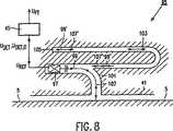
Der Detektor des Oberflächenmaterials umfasst eine Parallelleitung, durch die ein Teil der durch den Vibrationsgenerator erzeugten Luftvibrationen direkt an den Vibrationsdetektor geleitet werden kann. Die Eigenschaften des Vibrationsgenerators und des Vibrationsdetektors können sich infolge von Alterung oder Temperaturschwankungen ändern. Die Teile der mit Unterbrechungen erzeugten Luftvibrationen, die während des Betriebs durch die Parallelleitung geleitet werden, und der Teil der mit Unterbrechungen erzeugten Luftvibrationen, der während des Betriebs über die zu behandelnde Oberfläche geleitet wird, erreichen den Vibrationsdetektor zu unterschiedlichen Zeitpunkten. Dies macht es für den Vibrationsdetektor möglich, ein Verhältnis zwischen der Amplitude der erzeugten Luftvibrationen, die durch die zu behandelnde Oberfläche reflektiert werden, und der ursprünglichen Amplitude der erzeugten Luftvibrationen zu messen. Das Verhältnis ist im Wesentlichen unabhängig von der Temperatur und der Alterung des Vibrationsgenerators und des Vibrationsdetektors. Die durch die Parallelleitung geleiteten Luftvibrationen dienen somit als eine Referenz, mit der die Amplitude der durch die zu behandelnde Oberfläche reflektierten Luftvibrationen durch den Detektor des Oberflächenmaterials verglichen werden können.The surface material detector comprises a parallel line through which a portion of the air vibrations generated by the vibration generator can be directed to the vibration detector. The characteristics of the vibration generator and the vibration detector may change due to aging or temperature variations. The parts of the intermittent generated air vibrations, which are passed during operation by the parallel line, and the part of the intermittently generated air vibrations, which is passed during operation on the surface to be treated, reach the vibration detector at different times. This makes it possible for the vibration detector to measure a relationship between the amplitude of the generated air vibrations reflected by the surface to be treated and the original amplitude of the generated air vibrations. The ratio is substantially independent of the temperature and aging of the vibration generator and the vibration detector. The air vibrations conducted by the parallel line thus serve as a reference with which the amplitude of the air vibrations reflected by the surface to be treated can be compared by the detector of the surface material.
Eine weitere Ausführungsform einer elektrischen Flächenbehandlungsvorrichtung gemäß der Erfindung ist dadurch gekennzeichnet, dass die Parallelleitung ein blindes Ende hat und in der Nähe dieses Endes mit einem Endreflektor zum Zurückreflektieren der in die Parallelleitung geleiteten Luftvibrationen versehen ist. In dieser Ausführungsform wird ein Vibrationsgenerator verwendet, der die Luftvibrationen mit Unterbrechungen erzeugt und der auch umgeschaltet werden kann, um den Vibrationsdetektor zu bilden. Der Teil der Luftvibrationen, der während des Betriebs durch die Parallelleitung geleitetet wird, wird durch den Endreflektor zurück in die Parallelleitung reflektiert und erreicht den Vibrationsgenerator, der nun auf einen Vibrationsdetektor umgeschaltet wurde, um eine Referenz zu bilden. Auf diese Weise wird eine besonders einfache und praktische Konstruktion des Detektors des Oberflächenmaterials bereitgestellt.A further embodiment of an electrical surface treatment device according to the invention is characterized in that the parallel line has a blind end and is provided in the vicinity of this end with an end reflector for reflecting back the air vibrations conducted into the parallel line. In this embodiment, a vibration generator is used which generates the air vibrations intermittently and which can also be switched to form the vibration detector. The portion of the air vibrations passed through the parallel line during operation is reflected back into the parallel line by the end reflector and reaches the vibration generator, which has now been switched to a vibration detector to form a reference. In this way, a particularly simple and practical construction of the detector of the surface material is provided.
Die Erfindung betrifft weiterhin ein Zusatzteil zur Verwendung in einer elektrischen Oberflächenbehandlungsvorrichtung gemäß der Erfindung, wobei dieses Zusatzteil eine Saugdüse umfasst, die mit dem Detektor zur Ermittlung des Oberflächentyps versehen ist.The invention further relates to an attachment for use in an electrical surface treatment apparatus according to the invention, said attachment comprising a suction nozzle provided with the surface-type detection detector.
Ein Zusatzteil gemäß der Erfindung ist dadurch gekennzeichnet, dass der Vibrationsgenerator und der Vibrationsdetektor des Detektors des Oberflächenmaterials in einem Detektionsraum angeordnet sind, der während des Betriebs durch die zu behandelnde Oberfläche und durch eine untere Seite einer Saugdüse des Zusatzteils begrenzt ist. Da der Vibrationsgenerator und der Vibrationsdetektor in diesem Detektionsraum angeordnet sind, befinden sich der Vibrationsgenerator und der Vibrationsdetektor in unmittelbarer Nähe der zu behandelnden Oberfläche, derart, dass ein zuverlässiger Betrieb des Detektors des Oberflächenmaterials erreicht wird. Die akustischen Eigenschaften des Detektionsraums werden während des Betriebs in hohem Maße durch das zu behandelnde Oberflächenmaterial beeinflusst, derart, dass der Detektor des Oberflächenmaterials eine starke Unterscheidungsfähigkeit haben wird.An attachment according to the invention is characterized in that the vibration generator and the vibration detector of the surface material detector are arranged in a detection space bounded during operation by the surface to be treated and by a lower side of a suction nozzle of the attachment. Since the vibration generator and the vibration detector are disposed in this detection space, the vibration generator and the vibration detector are in close proximity to the surface to be treated, such that reliable operation of the surface material detector is achieved. The acoustic properties of the detection space are greatly influenced during operation by the surface material to be treated, such that the surface material detector will have a strong discriminating capability.
Eine besondere Ausführungsform eines Zusatzteils gemäß der Erfindung ist dadurch gekennzeichnet, dass der Vibrationsgenerator und der Vibrationsdetektor in einer in der unteren Seite der Saugdüse bereitgestellten Vertiefung angeordnet sind. Die Verwendung der Vertiefung vergrößert den Detektionsraum des Detektors des Oberflächenmaterials, wodurch die akustischen Eigenschaften des Detektionsraums beeinflusst werden. Die akustischen Eigenschaften des Detektors des Oberflächenmaterials werden in dieser Vertiefung, der eine geeignete Form gegeben wird, optimiert.A particular embodiment of an attachment according to the invention is characterized in that the vibration generator and the vibration detector are arranged in a recess provided in the lower side of the suction nozzle. The use of the recess increases the detection space of the detector of the surface material, whereby the acoustic properties of the detection space are influenced. The acoustic properties of the surface material detector are optimized in this well, which is given a suitable shape.
Eine weitere Ausführungsform eines Zusatzteils gemäß der Erfindung ist dadurch gekennzeichnet, dass der Vibrationsgenerator und der Vibrationsdetektor jeweils in einem in der unteren Seite der Saugdüse bereitgestellten separaten kanalartigen Hohlraum angeordnet sind. Die Verwendung dieser separaten kanalartigen Hohlräume erreicht, dass die während des Betriebs durch den Vibrationsgenerator erzeugten Luftvibrationen im Wesentlichen vollständig durch die zu behandelnde Oberfläche reflektiert werden, derart, dass ein direktes Nebensprechen vom Vibrationsgenerator zum Vibrationsdetektor so weit als möglich verhindert wird.A further embodiment of an attachment according to the invention is characterized in that the vibration generator and the vibration detector are each arranged in a provided in the lower side of the suction nozzle separate channel-like cavity. The use of these separate channel-like cavities ensures that the air vibrations generated during operation by the vibration generator are substantially completely reflected by the surface to be treated, such that direct crosstalk from the vibration generator to the vibration detector is prevented as much as possible.
Die Erfindung wird nun untenstehend mit mehr Details unter Bezugnahme auf die Zeichnungen beschrieben werden, in denen:The invention will now be described below in more detail with reference to the drawings, in which:
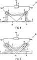
Die in
Wie
Die erste Ausführungsform des in
Da das Ausgangssignal UDET des Vibrationsdetektors
Die erzeugten Luftvibrationen
Es wurde herausgefunden, dass das Ausgangssignal UFT des Detektors des Oberflächenmaterials
In der zweiten, dritten, vierten, fünften und sechsten Ausführungsform eines Detektors des Oberflächenmaterials gemäß der Erfindung, die in
In der dritten Ausführungsform eines Detektors eines Oberflächenmaterials
In der vierten Ausführungsform des Detektors des Oberflächenmaterials
In der fünften Ausführungsform eines Detektors des Oberflächenmaterials
Die sechste Ausführungsform eines Detektors des Oberflächenmaterials
Es wird darauf hingewiesen, dass die Erfindung nicht nur Staubsauger, sondern auch andere elektrische Flächenbehandlungsvorrichtungen unterschiedlicher Arten betrifft, die mit Detektoren zum Ermitteln eines zu behandelnden Oberflächenmaterials versehen sind. Beispiele dafür, die erwähnt werden können, sind elektrische Poliermaschinen, elektrische Fußbodenmops, elektrische Dampfreiniger und elektrische Schamponiergeräte. In solchen elektrischen Flächenbehandlungsvorrichtungen gemäß der Erfindung wird das Ausgangssignal des Detektors des Oberflächenmaterials zum Beispiel an ein elektrisches Steuerelement geliefert, durch das der Betrieb der Flächenbehandlungsvorrichtung gesteuert wird. In einer elektrischen Poliervorrichtung kann daher zum Beispiel eine Rotationsgeschwindigkeit einer Polierbürste der Poliervorrichtung als eine Funktion des Ausgangssignals des Detektors des Oberflächenmaterials gesteuert werden, während in einem elektrischen Dampfreiniger und einem elektrischen Schamponiergerät zum Beispiel die Menge von zu lieferndem Dampf und beziehungsweise die Menge von zu lieferndem Shampoo als eine Funktion des Ausgangssignals des Detektors des Oberflächenmaterials gesteuert werden können.It should be noted that the invention relates not only to vacuum cleaners but also to other electrical surface treatment devices of various types provided with detectors for detecting a surface material to be treated. Examples which may be mentioned are electric polishing machines, electric floor mops, electric steam cleaners and electric shampooing machines. In such surface electric treatment apparatuses according to the invention, the output signal of the surface material detector is supplied to, for example, an electric control element by which the operation of the surface treatment apparatus is controlled. In an electric polishing apparatus, therefore, for example, a rotation speed of a polishing brush of the polishing apparatus can be controlled as a function of the output of the surface material detector, while in an electric steam cleaner and an electric shampooing apparatus, for example, the amount of steam to be supplied and / or the amount to be supplied Shampoo can be controlled as a function of the output signal of the detector of the surface material.
Die vorhergehend beschriebenen Staubsauger sind Bodenstaubsauger. Es wird darauf hingewiesen, dass die Erfindung ebenfalls so genannte Standstaubsauger abdeckt, in denen eine Saugdüse über ein Rohr an einen Handgriff gekoppelt ist, während ein darin untergebrachtes Gehäuse mit einer Saugeinheit an diesem Rohr befestigt ist. Die Erfindung betrifft zum Beispiel auch zentrale Staubsauganlagen, wo ein oder mehrere Saugzusatzgeräte mit einer Anzahl von Saugverbindungspunkten eines festen Systems von in einem Gebäude integrierten Saugleitungen verbunden werden können.The previously described vacuum cleaners are vacuum cleaners. It should be noted that the invention also covers so-called upright vacuum cleaners, in which a suction nozzle is coupled via a pipe to a handle, while a housing housed therein with a suction unit is attached to this pipe. The invention also relates, for example, to central vacuum cleaning systems where one or more suction attachments can be connected to a number of suction connection points of a fixed system of intake manifolds integrated in a building.
Es wird ferner darauf hingewiesen, dass anstatt der vorhergehend beschriebenen Amplitude auch eine unterschiedliche physische Größe der durch die zu behandelnde Oberfläche reflektierten Luftvibrationen mittels des Vibrationsdetektors gemäß der Erfindung gemessen werden kann. Es ist daher für den Vibrationsdetektor zum Beispiel möglich, ein Frequenzspektrum der durch die zu behandelnde Oberfläche reflektierten Luftvibrationen zu messen. Ein anderes Beispiel, das erwähnt werden kann, ist eine Vibrationsgeschwindigkeit der vibrierenden Luftpartikel.It is further noted that instead of the amplitude described above, a different physical quantity of the air vibrations reflected by the surface to be treated can be measured by means of the vibration detector according to the invention. It is therefore possible for the vibration detector, for example, to measure a frequency spectrum of the air vibrations reflected by the surface to be treated. Another example that may be mentioned is a vibration velocity of the vibrating air particles.
Es wird ferner darauf hingewiesen, dass der Detektor des Oberflächenmaterials gemäß der Erfindung auch an einem Standort angeordnet werden kann, der sich von der Saugdüse
Zuletzt wird darauf hingewiesen, dass ein anderer Typ von Vibrationsgenerator und ein anderer Typ von Vibrationsdetektor statt des vorhergehen genannten piezoelektrischen Vibrationsgenerators
Claims (14)
Translated fromGermanApplications Claiming Priority (4)
| Application Number | Priority Date | Filing Date | Title |
|---|---|---|---|
| EP97202623 | 1997-08-25 | ||
| EP97202623 | 1997-08-25 | ||
| PCT/IB1998/000996WO1999009874A1 (en) | 1997-08-25 | 1998-06-29 | Electrical surface treatment device with an acoustic surface type detector |
| EP98925883AEP0939598B2 (en) | 1997-08-25 | 1998-06-29 | Electrical surface treatment device with an acoustic surface type detector |
Publications (3)
| Publication Number | Publication Date |
|---|---|
| DE69832957D1 DE69832957D1 (en) | 2006-02-02 |
| DE69832957T2 DE69832957T2 (en) | 2006-08-24 |
| DE69832957T3true DE69832957T3 (en) | 2013-11-21 |
Family
ID=8228678
Family Applications (1)
| Application Number | Title | Priority Date | Filing Date |
|---|---|---|---|
| DE69832957TExpired - LifetimeDE69832957T3 (en) | 1997-08-25 | 1998-06-29 | ELECTRIC SURFACE TREATMENT DEVICE WITH ACOUSTIC DETECTOR OF SURFACE MATERIAL |
Country Status (7)
| Country | Link |
|---|---|
| US (1) | US6076227A (en) |
| EP (1) | EP0939598B2 (en) |
| JP (2) | JP4282772B2 (en) |
| KR (1) | KR100516315B1 (en) |
| CN (1) | CN1155326C (en) |
| DE (1) | DE69832957T3 (en) |
| WO (1) | WO1999009874A1 (en) |
Families Citing this family (70)
| Publication number | Priority date | Publication date | Assignee | Title |
|---|---|---|---|---|
| US7155308B2 (en) | 2000-01-24 | 2006-12-26 | Irobot Corporation | Robot obstacle detection system |
| US8412377B2 (en) | 2000-01-24 | 2013-04-02 | Irobot Corporation | Obstacle following sensor scheme for a mobile robot |
| US8788092B2 (en) | 2000-01-24 | 2014-07-22 | Irobot Corporation | Obstacle following sensor scheme for a mobile robot |
| US6956348B2 (en)* | 2004-01-28 | 2005-10-18 | Irobot Corporation | Debris sensor for cleaning apparatus |
| US7571511B2 (en) | 2002-01-03 | 2009-08-11 | Irobot Corporation | Autonomous floor-cleaning robot |
| US6690134B1 (en) | 2001-01-24 | 2004-02-10 | Irobot Corporation | Method and system for robot localization and confinement |
| US6810305B2 (en)* | 2001-02-16 | 2004-10-26 | The Procter & Gamble Company | Obstruction management system for robots |
| US8396592B2 (en) | 2001-06-12 | 2013-03-12 | Irobot Corporation | Method and system for multi-mode coverage for an autonomous robot |
| US7429843B2 (en) | 2001-06-12 | 2008-09-30 | Irobot Corporation | Method and system for multi-mode coverage for an autonomous robot |
| IL145680A0 (en) | 2001-09-26 | 2002-06-30 | Friendly Robotics Ltd | Robotic vacuum cleaner |
| EP1441632B1 (en)* | 2001-09-26 | 2013-05-01 | F. Robotics Acquisitions Ltd. | Robotic vacuum cleaner |
| US9128486B2 (en) | 2002-01-24 | 2015-09-08 | Irobot Corporation | Navigational control system for a robotic device |
| US8428778B2 (en) | 2002-09-13 | 2013-04-23 | Irobot Corporation | Navigational control system for a robotic device |
| US8386081B2 (en) | 2002-09-13 | 2013-02-26 | Irobot Corporation | Navigational control system for a robotic device |
| US7237298B2 (en) | 2003-09-19 | 2007-07-03 | Royal Appliance Mfg. Co. | Sensors and associated methods for controlling a vacuum cleaner |
| US7599758B2 (en) | 2003-09-19 | 2009-10-06 | Royal Appliance Mfg. Co. | Sensors and associated methods for controlling a vacuum cleaner |
| US7424766B2 (en) | 2003-09-19 | 2008-09-16 | Royal Appliance Mfg. Co. | Sensors and associated methods for controlling a vacuum cleaner |
| US7332890B2 (en) | 2004-01-21 | 2008-02-19 | Irobot Corporation | Autonomous robot auto-docking and energy management systems and methods |
| KR20140092417A (en)* | 2004-01-28 | 2014-07-23 | 아이로보트 코퍼레이션 | Debris sensor for cleaning apparatus |
| DE102004010827B4 (en)* | 2004-02-27 | 2006-01-05 | Alfred Kärcher Gmbh & Co. Kg | Soil cultivation device and method for its control |
| WO2005098476A1 (en) | 2004-03-29 | 2005-10-20 | Evolution Robotics, Inc. | Method and apparatus for position estimation using reflected light sources |
| SG174000A1 (en) | 2004-06-24 | 2011-09-29 | Irobot Corp | Remote control scheduler and method for autonomous robotic device |
| US8972052B2 (en) | 2004-07-07 | 2015-03-03 | Irobot Corporation | Celestial navigation system for an autonomous vehicle |
| US7706917B1 (en)* | 2004-07-07 | 2010-04-27 | Irobot Corporation | Celestial navigation system for an autonomous robot |
| KR101084122B1 (en)* | 2004-07-30 | 2011-11-17 | 엘지전자 주식회사 | Suction nozzle of vacuum cleaner |
| US8392021B2 (en) | 2005-02-18 | 2013-03-05 | Irobot Corporation | Autonomous surface cleaning robot for wet cleaning |
| US7389156B2 (en) | 2005-02-18 | 2008-06-17 | Irobot Corporation | Autonomous surface cleaning robot for wet and dry cleaning |
| US7620476B2 (en) | 2005-02-18 | 2009-11-17 | Irobot Corporation | Autonomous surface cleaning robot for dry cleaning |
| KR101240732B1 (en) | 2005-02-18 | 2013-03-07 | 아이로보트 코퍼레이션 | Autonomous surface cleaning robot for wet and dry cleaning |
| US8930023B2 (en) | 2009-11-06 | 2015-01-06 | Irobot Corporation | Localization by learning of wave-signal distributions |
| US20070017061A1 (en)* | 2005-07-20 | 2007-01-25 | Jason Yan | Steering control sensor for an automatic vacuum cleaner |
| EP2270619B1 (en) | 2005-12-02 | 2013-05-08 | iRobot Corporation | Modular robot |
| EP2816434A3 (en) | 2005-12-02 | 2015-01-28 | iRobot Corporation | Autonomous coverage robot |
| US9144360B2 (en) | 2005-12-02 | 2015-09-29 | Irobot Corporation | Autonomous coverage robot navigation system |
| KR101099808B1 (en) | 2005-12-02 | 2011-12-27 | 아이로보트 코퍼레이션 | Robotic systems |
| KR101300492B1 (en) | 2005-12-02 | 2013-09-02 | 아이로보트 코퍼레이션 | Coverage robot mobility |
| EP3067771B1 (en) | 2006-03-17 | 2017-11-08 | iRobot Corporation | Robot confinement |
| US20090044370A1 (en) | 2006-05-19 | 2009-02-19 | Irobot Corporation | Removing debris from cleaning robots |
| US8417383B2 (en) | 2006-05-31 | 2013-04-09 | Irobot Corporation | Detecting robot stasis |
| ES2571739T3 (en) | 2007-05-09 | 2016-05-26 | Irobot Corp | Autonomous compact covering robot |
| WO2011103198A1 (en) | 2010-02-16 | 2011-08-25 | Irobot Corporation | Vacuum brush |
| EP2659260B1 (en) | 2010-12-30 | 2019-11-20 | iRobot Corporation | Debris monitoring |
| EP2701570B1 (en) | 2011-04-29 | 2019-02-13 | iRobot Corporation | An autonomous mobile robot |
| US11471020B2 (en) | 2011-04-29 | 2022-10-18 | Irobot Corporation | Robotic vacuum cleaning system |
| JP2014236838A (en)* | 2013-06-07 | 2014-12-18 | シャープ株式会社 | Self-propelled vacuum cleaner |
| DE102013223864A1 (en)* | 2013-11-21 | 2015-05-21 | BSH Hausgeräte GmbH | Method of operating a vacuum cleaner and vacuum cleaner |
| EP3126921B1 (en) | 2014-03-31 | 2021-02-24 | iRobot Corporation | Autonomous mobile robot |
| US9510505B2 (en) | 2014-10-10 | 2016-12-06 | Irobot Corporation | Autonomous robot localization |
| US9516806B2 (en) | 2014-10-10 | 2016-12-13 | Irobot Corporation | Robotic lawn mowing boundary determination |
| US9420741B2 (en) | 2014-12-15 | 2016-08-23 | Irobot Corporation | Robot lawnmower mapping |
| US9538702B2 (en) | 2014-12-22 | 2017-01-10 | Irobot Corporation | Robotic mowing of separated lawn areas |
| US11115798B2 (en) | 2015-07-23 | 2021-09-07 | Irobot Corporation | Pairing a beacon with a mobile robot |
| US10034421B2 (en) | 2015-07-24 | 2018-07-31 | Irobot Corporation | Controlling robotic lawnmowers |
| US10021830B2 (en) | 2016-02-02 | 2018-07-17 | Irobot Corporation | Blade assembly for a grass cutting mobile robot |
| US10459063B2 (en) | 2016-02-16 | 2019-10-29 | Irobot Corporation | Ranging and angle of arrival antenna system for a mobile robot |
| US10512384B2 (en) | 2016-12-15 | 2019-12-24 | Irobot Corporation | Cleaning roller for cleaning robots |
| DE102017101936A1 (en)* | 2017-02-01 | 2018-08-02 | Vorwerk & Co. Interholding Gesellschaft mit beschränkter Haftung | Automatically movable soil tillage implement |
| WO2019013989A1 (en) | 2017-07-14 | 2019-01-17 | Irobot Corporation | Blade assembly for a grass cutting mobile robot |
| DE102017116747A1 (en)* | 2017-07-25 | 2019-01-31 | Vorwerk & Co. Interholding Gmbh | Floor cleaning device and method for its operation |
| US10595624B2 (en) | 2017-07-25 | 2020-03-24 | Irobot Corporation | Cleaning roller for cleaning robots |
| US11202543B2 (en) | 2018-01-17 | 2021-12-21 | Techtronic Floor Care Technology Limited | System and method for operating a cleaning system based on a surface to be cleaned |
| US11109727B2 (en) | 2019-02-28 | 2021-09-07 | Irobot Corporation | Cleaning rollers for cleaning robots |
| CN110018239B (en)* | 2019-04-04 | 2022-07-08 | 珠海一微半导体股份有限公司 | Carpet detection method |
| CN109907703A (en)* | 2019-04-04 | 2019-06-21 | 珠海市一微半导体有限公司 | A kind of mobile robot |
| CN110514744B (en) | 2019-08-20 | 2020-05-05 | 珠海市一微半导体有限公司 | Correction method and detection method for judgment threshold of ground medium |
| CN110477814B (en)* | 2019-08-20 | 2023-08-15 | 珠海一微半导体股份有限公司 | Mobile robot for carpet detection |
| CN110403540A (en)* | 2019-08-20 | 2019-11-05 | 珠海市一微半导体有限公司 | Toning equipment and clean robot for the detection of ground medium |
| CN114980787B (en) | 2020-03-25 | 2024-01-26 | 科德宝两合公司 | Method and assembly for identifying a substrate |
| CN112198222B (en)* | 2020-09-17 | 2022-04-05 | 美智纵横科技有限责任公司 | Ground material identification method, system, equipment and storage medium |
| CN113384188A (en)* | 2021-06-22 | 2021-09-14 | 深圳前海帕拓逊网络技术有限公司 | Device for automatically identifying ground material and dust collector |
Family Cites Families (19)
| Publication number | Priority date | Publication date | Assignee | Title |
|---|---|---|---|---|
| US4574637A (en)* | 1984-08-03 | 1986-03-11 | Univ Ohio | Method for measuring surface and near surface properties of materials |
| JP2606842B2 (en)* | 1987-05-30 | 1997-05-07 | 株式会社東芝 | Electric vacuum cleaner |
| JPS63300732A (en)* | 1987-05-30 | 1988-12-07 | 株式会社東芝 | Electric cleaner |
| JP2820407B2 (en)† | 1988-02-16 | 1998-11-05 | 松下電器産業株式会社 | Self-propelled vacuum cleaner |
| KR910006885B1 (en)* | 1988-08-15 | 1991-09-10 | 미쯔비시 덴끼 가부시기가이샤 | Floor detector for vacuum cleaners |
| JPH02102629A (en) | 1988-10-11 | 1990-04-16 | Mitsubishi Electric Corp | vacuum cleaner |
| JPH0824652B2 (en)* | 1988-12-06 | 1996-03-13 | 松下電器産業株式会社 | Electric vacuum cleaner |
| JPH0377519A (en)† | 1989-08-18 | 1991-04-03 | Matsushita Electric Ind Co Ltd | Floor surface discrimination device |
| US5144715A (en)* | 1989-08-18 | 1992-09-08 | Matsushita Electric Industrial Co., Ltd. | Vacuum cleaner and method of determining type of floor surface being cleaned thereby |
| EP0423670B1 (en)* | 1989-10-18 | 1994-12-28 | Hitachi, Ltd. | Vacuum cleaner and method of controlling the same |
| JPH03212249A (en)† | 1990-01-17 | 1991-09-17 | Matsushita Electric Ind Co Ltd | Floor surface judging device |
| KR920007588B1 (en)† | 1990-08-29 | 1992-09-08 | 주식회사 금성사 | Electric vacuum cleaner |
| JPH04126115A (en)† | 1990-09-18 | 1992-04-27 | Sanyo Electric Co Ltd | Vacuum cleaner |
| JP2900595B2 (en)* | 1990-11-22 | 1999-06-02 | 松下電器産業株式会社 | Vacuum cleaner |
| JPH06261853A (en)† | 1993-03-11 | 1994-09-20 | Matsushita Electric Ind Co Ltd | Floor surface detector for vacuum cleaner |
| FR2708188A1 (en)* | 1993-07-28 | 1995-02-03 | Philips Laboratoire Electroniq | Vacuum cleaner with means of soil detection and adjustment of the engine power according to the detected soil. |
| DE4333645A1 (en)† | 1993-10-02 | 1995-04-06 | Rossendorf Forschzent | Method for minimizing the influence of resonance fluctuations on the measurement signal in ultrasound transmission tests |
| DE4418887C1 (en)† | 1994-05-30 | 1995-04-06 | Siemens Ag | Method for producing an ultrasonic transducer arrangement |
| JPH07313418A (en)† | 1994-05-30 | 1995-12-05 | Nippon Ceramic Co Ltd | Vacuum cleaner |
- 1998
- 1998-06-29DEDE69832957Tpatent/DE69832957T3/ennot_activeExpired - Lifetime
- 1998-06-29KRKR10-1999-7003583Apatent/KR100516315B1/ennot_activeExpired - Lifetime
- 1998-06-29CNCNB988015714Apatent/CN1155326C/ennot_activeExpired - Lifetime
- 1998-06-29WOPCT/IB1998/000996patent/WO1999009874A1/enactiveIP Right Grant
- 1998-06-29JPJP51409199Apatent/JP4282772B2/ennot_activeExpired - Lifetime
- 1998-06-29EPEP98925883Apatent/EP0939598B2/ennot_activeExpired - Lifetime
- 1998-08-17USUS09/135,366patent/US6076227A/ennot_activeExpired - Lifetime
- 2008
- 2008-09-29JPJP2008249909Apatent/JP4829282B2/ennot_activeExpired - Lifetime
Also Published As
| Publication number | Publication date |
|---|---|
| JP2001504744A (en) | 2001-04-10 |
| JP4282772B2 (en) | 2009-06-24 |
| CN1155326C (en) | 2004-06-30 |
| JP4829282B2 (en) | 2011-12-07 |
| DE69832957D1 (en) | 2006-02-02 |
| WO1999009874A1 (en) | 1999-03-04 |
| CN1242692A (en) | 2000-01-26 |
| DE69832957T2 (en) | 2006-08-24 |
| US6076227A (en) | 2000-06-20 |
| EP0939598A1 (en) | 1999-09-08 |
| KR20000068829A (en) | 2000-11-25 |
| EP0939598B1 (en) | 2005-12-28 |
| KR100516315B1 (en) | 2005-09-23 |
| EP0939598B2 (en) | 2013-03-20 |
| JP2009050710A (en) | 2009-03-12 |
Similar Documents
| Publication | Publication Date | Title |
|---|---|---|
| DE69832957T3 (en) | ELECTRIC SURFACE TREATMENT DEVICE WITH ACOUSTIC DETECTOR OF SURFACE MATERIAL | |
| DE60030100T2 (en) | DEVICE AND METHOD FOR VENTILATING TOILETS BY MEANS OF A RADAR SYSTEM | |
| DE69632490T2 (en) | Method and device for in-situ control and determination of the end of chemical mechanical grading | |
| Phillips et al. | Responses of single neurons in posterior field of cat auditory cortex to tonal stimulation | |
| DE3732699C2 (en) | Implantable pacemaker | |
| DE69912285T2 (en) | Measurement of the speed of sound in a gas with a small spherical resonator and a non-radial mode for the analysis of gas mixtures | |
| DE19806559B4 (en) | Method and device for treating dishes in dishwashers | |
| EP1136027B1 (en) | Floor treating apparatus and method for recognizing a state of floor respectively for aligning the drive movement | |
| DE69028431T2 (en) | heater | |
| DE2915069C2 (en) | Time-controlled amplifier for side scan sonar | |
| DE69818522T2 (en) | DETERMINATION OF ACOUSTIC SPEED IN THE BONE | |
| DE3702355C2 (en) | ||
| DE102004036459A1 (en) | Cleaning robot equipped with a negative ion generator | |
| DE69010400T2 (en) | Suction hose for a vacuum cleaner. | |
| EP3569124A1 (en) | Cleaning device | |
| DE3607262A1 (en) | CIRCUIT FOR MONITORING THE CONTACT BETWEEN AN ULTRASONIC TRANSDUCER AND A PATIENT | |
| AT501052B1 (en) | METHOD AND DEVICE FOR ABSORPTION SPECTROSCOPY | |
| DE69910794T2 (en) | SYNTHETIZING A SINE WAVE | |
| DE10344599B4 (en) | Tilt angle measurement device | |
| DE3241814C2 (en) | Ultrasonic microscope | |
| EP1781159A2 (en) | Device for measuring a position of a surgical instrument | |
| DE19811876A1 (en) | Water turbidity measuring apparatus | |
| WO1993002623A1 (en) | Process and device for measuring the thickness of the mucous membrane of a jawbone ridge | |
| DE69426912T2 (en) | Local hydromassage device | |
| DE102018128687B4 (en) | Attachment for a cleaning device, system and method for wet cleaning a surface |
Legal Events
| Date | Code | Title | Description |
|---|---|---|---|
| 8328 | Change in the person/name/address of the agent | Representative=s name:VOLMER, G., DIPL.-ING., PAT.-ANW., 52066 AACHEN | |
| 8363 | Opposition against the patent |