DE602004010914T3 - Set of floor panels - Google Patents
Set of floor panelsDownload PDFInfo
- Publication number
- DE602004010914T3 DE602004010914T3DE602004010914TDE602004010914TDE602004010914T3DE 602004010914 T3DE602004010914 T3DE 602004010914T3DE 602004010914 TDE602004010914 TDE 602004010914TDE 602004010914 TDE602004010914 TDE 602004010914TDE 602004010914 T3DE602004010914 T3DE 602004010914T3
- Authority
- DE
- Germany
- Prior art keywords
- plate
- flexible spring
- groove
- spring
- locking
- Prior art date
- Legal status (The legal status is an assumption and is not a legal conclusion. Google has not performed a legal analysis and makes no representation as to the accuracy of the status listed.)
- Expired - Lifetime
Links
- 238000006073displacement reactionMethods0.000claimsabstractdescription44
- 238000005452bendingMethods0.000claimsdescription7
- 230000009471actionEffects0.000claimsdescription5
- 239000002861polymer materialSubstances0.000claims1
- 238000009434installationMethods0.000abstractdescription14
- 238000004519manufacturing processMethods0.000abstractdescription14
- 238000000034methodMethods0.000abstractdescription14
- 239000000463materialSubstances0.000description26
- 230000008901benefitEffects0.000description10
- 239000011162core materialSubstances0.000description10
- 239000004033plasticSubstances0.000description7
- 239000002023woodSubstances0.000description7
- 239000011094fiberboardSubstances0.000description6
- 239000002344surface layerSubstances0.000description6
- 239000010410layerSubstances0.000description5
- 229920002522Wood fibrePolymers0.000description4
- 210000003746featherAnatomy0.000description4
- 238000007667floatingMethods0.000description4
- 238000009408flooringMethods0.000description4
- 239000002025wood fiberSubstances0.000description4
- 229910052782aluminiumInorganic materials0.000description3
- XAGFODPZIPBFFR-UHFFFAOYSA-NaluminiumChemical compound[Al]XAGFODPZIPBFFR-UHFFFAOYSA-N0.000description3
- 239000003292glueSubstances0.000description3
- 239000000123paperSubstances0.000description3
- 238000007514turningMethods0.000description3
- 230000002349favourable effectEffects0.000description2
- 239000003365glass fiberSubstances0.000description2
- 238000001746injection mouldingMethods0.000description2
- 238000003780insertionMethods0.000description2
- 230000037431insertionEffects0.000description2
- 238000005304joiningMethods0.000description2
- 229910052751metalInorganic materials0.000description2
- 239000002184metalSubstances0.000description2
- 230000036316preloadEffects0.000description2
- 230000008569processEffects0.000description2
- 238000000926separation methodMethods0.000description2
- 239000007787solidSubstances0.000description2
- -1HDFSubstances0.000description1
- 239000004677NylonSubstances0.000description1
- 238000004026adhesive bondingMethods0.000description1
- 230000000903blocking effectEffects0.000description1
- 230000008859changeEffects0.000description1
- 239000007799corkSubstances0.000description1
- 230000001419dependent effectEffects0.000description1
- 238000005516engineering processMethods0.000description1
- 239000000835fiberSubstances0.000description1
- 239000002783friction materialSubstances0.000description1
- 238000003475laminationMethods0.000description1
- 238000003754machiningMethods0.000description1
- 150000002739metalsChemical class0.000description1
- 238000000465mouldingMethods0.000description1
- 229920001778nylonPolymers0.000description1
- 238000004806packaging method and processMethods0.000description1
- 239000011120plywoodSubstances0.000description1
- 239000004575stoneSubstances0.000description1
- 239000000126substanceSubstances0.000description1
Images


Classifications
- E—FIXED CONSTRUCTIONS
- E04—BUILDING
- E04F—FINISHING WORK ON BUILDINGS, e.g. STAIRS, FLOORS
- E04F15/00—Flooring
- E04F15/02—Flooring or floor layers composed of a number of similar elements
- E04F15/02038—Flooring or floor layers composed of a number of similar elements characterised by tongue and groove connections between neighbouring flooring elements
- E—FIXED CONSTRUCTIONS
- E04—BUILDING
- E04F—FINISHING WORK ON BUILDINGS, e.g. STAIRS, FLOORS
- E04F15/00—Flooring
- E04F15/02—Flooring or floor layers composed of a number of similar elements
- E—FIXED CONSTRUCTIONS
- E04—BUILDING
- E04B—GENERAL BUILDING CONSTRUCTIONS; WALLS, e.g. PARTITIONS; ROOFS; FLOORS; CEILINGS; INSULATION OR OTHER PROTECTION OF BUILDINGS
- E04B5/00—Floors; Floor construction with regard to insulation; Connections specially adapted therefor
- E—FIXED CONSTRUCTIONS
- E04—BUILDING
- E04F—FINISHING WORK ON BUILDINGS, e.g. STAIRS, FLOORS
- E04F15/00—Flooring
- E—FIXED CONSTRUCTIONS
- E04—BUILDING
- E04F—FINISHING WORK ON BUILDINGS, e.g. STAIRS, FLOORS
- E04F21/00—Implements for finishing work on buildings
- E04F21/20—Implements for finishing work on buildings for laying flooring
- E04F21/22—Implements for finishing work on buildings for laying flooring of single elements, e.g. flooring cramps ; flexible webs
- F—MECHANICAL ENGINEERING; LIGHTING; HEATING; WEAPONS; BLASTING
- F16—ENGINEERING ELEMENTS AND UNITS; GENERAL MEASURES FOR PRODUCING AND MAINTAINING EFFECTIVE FUNCTIONING OF MACHINES OR INSTALLATIONS; THERMAL INSULATION IN GENERAL
- F16B—DEVICES FOR FASTENING OR SECURING CONSTRUCTIONAL ELEMENTS OR MACHINE PARTS TOGETHER, e.g. NAILS, BOLTS, CIRCLIPS, CLAMPS, CLIPS OR WEDGES; JOINTS OR JOINTING
- F16B5/00—Joining sheets or plates, e.g. panels, to one another or to strips or bars parallel to them
- E—FIXED CONSTRUCTIONS
- E04—BUILDING
- E04B—GENERAL BUILDING CONSTRUCTIONS; WALLS, e.g. PARTITIONS; ROOFS; FLOORS; CEILINGS; INSULATION OR OTHER PROTECTION OF BUILDINGS
- E04B1/00—Constructions in general; Structures which are not restricted either to walls, e.g. partitions, or floors or ceilings or roofs
- E04B1/38—Connections for building structures in general
- E04B1/541—Joints substantially without separate connecting elements, e.g. jointing by inter-engagement
- E—FIXED CONSTRUCTIONS
- E04—BUILDING
- E04B—GENERAL BUILDING CONSTRUCTIONS; WALLS, e.g. PARTITIONS; ROOFS; FLOORS; CEILINGS; INSULATION OR OTHER PROTECTION OF BUILDINGS
- E04B1/00—Constructions in general; Structures which are not restricted either to walls, e.g. partitions, or floors or ceilings or roofs
- E04B1/38—Connections for building structures in general
- E04B1/58—Connections for building structures in general of bar-shaped building elements
- E04B1/5806—Connections for building structures in general of bar-shaped building elements with a cross-section having an open profile
- E04B1/5818—Connections for building structures in general of bar-shaped building elements with a cross-section having an open profile of substantially U - form
- E—FIXED CONSTRUCTIONS
- E04—BUILDING
- E04F—FINISHING WORK ON BUILDINGS, e.g. STAIRS, FLOORS
- E04F15/00—Flooring
- E04F15/02—Flooring or floor layers composed of a number of similar elements
- E04F15/04—Flooring or floor layers composed of a number of similar elements only of wood or with a top layer of wood, e.g. with wooden or metal connecting members
- E—FIXED CONSTRUCTIONS
- E04—BUILDING
- E04F—FINISHING WORK ON BUILDINGS, e.g. STAIRS, FLOORS
- E04F2201/00—Joining sheets or plates or panels
- E04F2201/01—Joining sheets, plates or panels with edges in abutting relationship
- E04F2201/0107—Joining sheets, plates or panels with edges in abutting relationship by moving the sheets, plates or panels substantially in their own plane, perpendicular to the abutting edges
- E04F2201/0115—Joining sheets, plates or panels with edges in abutting relationship by moving the sheets, plates or panels substantially in their own plane, perpendicular to the abutting edges with snap action of the edge connectors
- E—FIXED CONSTRUCTIONS
- E04—BUILDING
- E04F—FINISHING WORK ON BUILDINGS, e.g. STAIRS, FLOORS
- E04F2201/00—Joining sheets or plates or panels
- E04F2201/01—Joining sheets, plates or panels with edges in abutting relationship
- E04F2201/0138—Joining sheets, plates or panels with edges in abutting relationship by moving the sheets, plates or panels perpendicular to the main plane
- E04F2201/0146—Joining sheets, plates or panels with edges in abutting relationship by moving the sheets, plates or panels perpendicular to the main plane with snap action of the edge connectors
- E—FIXED CONSTRUCTIONS
- E04—BUILDING
- E04F—FINISHING WORK ON BUILDINGS, e.g. STAIRS, FLOORS
- E04F2201/00—Joining sheets or plates or panels
- E04F2201/01—Joining sheets, plates or panels with edges in abutting relationship
- E04F2201/0153—Joining sheets, plates or panels with edges in abutting relationship by rotating the sheets, plates or panels around an axis which is parallel to the abutting edges, possibly combined with a sliding movement
- E—FIXED CONSTRUCTIONS
- E04—BUILDING
- E04F—FINISHING WORK ON BUILDINGS, e.g. STAIRS, FLOORS
- E04F2201/00—Joining sheets or plates or panels
- E04F2201/01—Joining sheets, plates or panels with edges in abutting relationship
- E04F2201/0169—Joining sheets, plates or panels with edges in abutting relationship by rotating the sheets, plates or panels around an axis which is perpendicular to the abutting edges and parallel to the main plane, possibly combined with a sliding movement
- E04F2201/0176—Joining sheets, plates or panels with edges in abutting relationship by rotating the sheets, plates or panels around an axis which is perpendicular to the abutting edges and parallel to the main plane, possibly combined with a sliding movement with snap action of the edge connectors
- E—FIXED CONSTRUCTIONS
- E04—BUILDING
- E04F—FINISHING WORK ON BUILDINGS, e.g. STAIRS, FLOORS
- E04F2201/00—Joining sheets or plates or panels
- E04F2201/02—Non-undercut connections, e.g. tongue and groove connections
- E04F2201/023—Non-undercut connections, e.g. tongue and groove connections with a continuous tongue or groove
- E—FIXED CONSTRUCTIONS
- E04—BUILDING
- E04F—FINISHING WORK ON BUILDINGS, e.g. STAIRS, FLOORS
- E04F2201/00—Joining sheets or plates or panels
- E04F2201/04—Other details of tongues or grooves
- E04F2201/042—Other details of tongues or grooves with grooves positioned on the rear-side of the panel
- E—FIXED CONSTRUCTIONS
- E04—BUILDING
- E04F—FINISHING WORK ON BUILDINGS, e.g. STAIRS, FLOORS
- E04F2201/00—Joining sheets or plates or panels
- E04F2201/05—Separate connectors or inserts, e.g. pegs, pins, keys or strips
- E04F2201/0523—Separate tongues; Interlocking keys, e.g. joining mouldings of circular, square or rectangular shape
- E04F2201/0547—Separate tongues; Interlocking keys, e.g. joining mouldings of circular, square or rectangular shape adapted to be moved perpendicular to the joint edge
- E—FIXED CONSTRUCTIONS
- E04—BUILDING
- E04F—FINISHING WORK ON BUILDINGS, e.g. STAIRS, FLOORS
- E04F2201/00—Joining sheets or plates or panels
- E04F2201/05—Separate connectors or inserts, e.g. pegs, pins, keys or strips
- E04F2201/0523—Separate tongues; Interlocking keys, e.g. joining mouldings of circular, square or rectangular shape
- E04F2201/0564—Separate tongues; Interlocking keys, e.g. joining mouldings of circular, square or rectangular shape depending on the use of specific materials
- E04F2201/0576—Separate tongues; Interlocking keys, e.g. joining mouldings of circular, square or rectangular shape depending on the use of specific materials of metal
- E—FIXED CONSTRUCTIONS
- E04—BUILDING
- E04F—FINISHING WORK ON BUILDINGS, e.g. STAIRS, FLOORS
- E04F2201/00—Joining sheets or plates or panels
- E04F2201/05—Separate connectors or inserts, e.g. pegs, pins, keys or strips
- E04F2201/0523—Separate tongues; Interlocking keys, e.g. joining mouldings of circular, square or rectangular shape
- E04F2201/0564—Separate tongues; Interlocking keys, e.g. joining mouldings of circular, square or rectangular shape depending on the use of specific materials
- E04F2201/0582—Separate tongues; Interlocking keys, e.g. joining mouldings of circular, square or rectangular shape depending on the use of specific materials of fibres or chips, e.g. bonded with synthetic resins
- E—FIXED CONSTRUCTIONS
- E04—BUILDING
- E04F—FINISHING WORK ON BUILDINGS, e.g. STAIRS, FLOORS
- E04F2201/00—Joining sheets or plates or panels
- E04F2201/05—Separate connectors or inserts, e.g. pegs, pins, keys or strips
- E04F2201/0523—Separate tongues; Interlocking keys, e.g. joining mouldings of circular, square or rectangular shape
- E04F2201/0564—Separate tongues; Interlocking keys, e.g. joining mouldings of circular, square or rectangular shape depending on the use of specific materials
- E04F2201/0588—Separate tongues; Interlocking keys, e.g. joining mouldings of circular, square or rectangular shape depending on the use of specific materials of organic plastics with or without reinforcements or filling materials
- F—MECHANICAL ENGINEERING; LIGHTING; HEATING; WEAPONS; BLASTING
- F16—ENGINEERING ELEMENTS AND UNITS; GENERAL MEASURES FOR PRODUCING AND MAINTAINING EFFECTIVE FUNCTIONING OF MACHINES OR INSTALLATIONS; THERMAL INSULATION IN GENERAL
- F16B—DEVICES FOR FASTENING OR SECURING CONSTRUCTIONAL ELEMENTS OR MACHINE PARTS TOGETHER, e.g. NAILS, BOLTS, CIRCLIPS, CLAMPS, CLIPS OR WEDGES; JOINTS OR JOINTING
- F16B5/00—Joining sheets or plates, e.g. panels, to one another or to strips or bars parallel to them
- F16B5/0004—Joining sheets, plates or panels in abutting relationship
- F16B5/0056—Joining sheets, plates or panels in abutting relationship by moving the sheets, plates or panels or the interlocking key perpendicular to the main plane
- F16B5/0076—Joining sheets, plates or panels in abutting relationship by moving the sheets, plates or panels or the interlocking key perpendicular to the main plane and using expanding clamps
- F—MECHANICAL ENGINEERING; LIGHTING; HEATING; WEAPONS; BLASTING
- F16—ENGINEERING ELEMENTS AND UNITS; GENERAL MEASURES FOR PRODUCING AND MAINTAINING EFFECTIVE FUNCTIONING OF MACHINES OR INSTALLATIONS; THERMAL INSULATION IN GENERAL
- F16B—DEVICES FOR FASTENING OR SECURING CONSTRUCTIONAL ELEMENTS OR MACHINE PARTS TOGETHER, e.g. NAILS, BOLTS, CIRCLIPS, CLAMPS, CLIPS OR WEDGES; JOINTS OR JOINTING
- F16B5/00—Joining sheets or plates, e.g. panels, to one another or to strips or bars parallel to them
- F16B5/0004—Joining sheets, plates or panels in abutting relationship
- F16B5/008—Joining sheets, plates or panels in abutting relationship by a rotating or sliding and rotating movement
Landscapes
- Engineering & Computer Science (AREA)
- Architecture (AREA)
- Civil Engineering (AREA)
- Structural Engineering (AREA)
- General Engineering & Computer Science (AREA)
- Physics & Mathematics (AREA)
- Electromagnetism (AREA)
- Mechanical Engineering (AREA)
- Floor Finish (AREA)
- Joining Of Building Structures In Genera (AREA)
- Steam Or Hot-Water Central Heating Systems (AREA)
- Finishing Walls (AREA)
- Connection Of Plates (AREA)
- Load-Bearing And Curtain Walls (AREA)
- Roof Covering Using Slabs Or Stiff Sheets (AREA)
- Conveying And Assembling Of Building Elements In Situ (AREA)
- Road Paving Structures (AREA)
Abstract
Description
Translated fromGermanTechnisches GebietTechnical area
Die Erfindung bezieht sich allgemein auf das Gebiet mechanischer Arretiersysteme für Bodenplatten und solche Bauplatten, die aus einem Brettmaterial hergestellt sind. Die Erfindung bezieht sich auf einen Satz von Bodenplatten, die mit einem derartigen Arretiersystem versehen sind.The invention relates generally to the field of mechanical locking systems for floor panels and such building panels made of board material. The invention relates to a set of floor panels provided with such a locking system.
Anwendungsgebiet der ErfindungField of application of the invention
Die vorliegende Erfindung eignet sich besonders für den Einsatz bei schwimmenden Fußböden, die aus Bodenplatten gebildet sind, die mechanisch mit einem in die Bodenplatte integrierten, d. h. werkseitig montierten, Arretiersystem verbunden werden und aus einer oder mehreren oberen Schichten aus Furnier, Zierlaminat oder Zierkunststoffmaterial, einem Zwischenkern aus Material auf Holzfasergrundlage oder Kunststoffmaterial und vorzugsweise einem unteren Gegenzug auf der Rückseite des Kerns bestehen. Die folgende Beschreibung von bekannten Techniken, Problemen bekannter Systeme und von Aufgaben und Merkmalen der Erfindung zielt daher als nicht einschränkendes Beispiel in erster Linie auf dieses Anwendungsgebiet und insbesondere auf Laminatböden ab, die als rechteckige Bodenplatten mit langen und kurzen Seiten ausgebildet sind, die sowohl an den langen als auch an den kurzen Seiten mechanisch verbunden werden sollen. Die langen und kurzen Seiten dienen in der Hauptsache zur Vereinfachung der Beschreibung der Erfindung. Die Platten könnten quadratisch sein, der Winkel der Seiten könnte nicht 90 Grad sein und sie könnten mehr als 4 Seiten haben. Es sollte betont werden, dass sich die Erfindung bei beliebigen Bodenplatten anwenden lässt, und sie könnte mit allen Arten bekannter Arretiersysteme, bei denen die Bodenplatten unter Verwendung eines mechanischen Arretiersystems in der horizontalen und der vertikalen Richtung verbunden werden sollen, kombiniert werden. Die Erfindung lässt sich daher auch beispielsweise bei Fußböden aus Massivholz, Parkettböden mit einem Kern aus Holz oder einem Material auf Holzfaserbasis und einer Oberfläche aus Holz oder Holzfurnier u. a., Fußböden mit einer bedruckten und vorzugsweise auch lackierten Oberfläche, und Fußböden mit einer Oberflächenschicht aus Kunststoff oder Kork, Linoleum oder Kautschuk anwenden. Eingeschlossen sind sogar Fußböden mit harten Oberflächen wie aus Stein, Fliesen u. a., sowie Fußböden mit einer weichen Verschleißschicht, beispielsweise auf eine Rückenschicht geklebtes Nadelvlies. Die Erfindung kann auch zum Verbinden von Bauplatten verwendet werden, die vorzugsweise ein Brettmaterial wie beispielsweise Wandpaneele, Decken, Möbelteile u. a. enthalten.The present invention is particularly suitable for use with floating floors formed of floor panels that are mechanically integrated with a floor panel integrated into the floorboard. H. factory-assembled, locking system are connected and consist of one or more upper layers of veneer, decorative laminate or decorative plastic material, an intermediate core of material based on wood fiber or plastic material and preferably a lower counter-pull on the back of the core. The following description of known techniques, problems of known systems and objects and features of the invention is therefore intended, as a non-limiting example, primarily in this field of application and in particular on laminate floors, which are formed as rectangular bottom plates with long and short sides, both at should be mechanically connected to the long and short sides. The long and short pages serve mainly to simplify the description of the invention. The plates could be square, the angle of the sides could not be 90 degrees and they could have more than 4 sides. It should be emphasized that the invention can be applied to any floor panel and it could be combined with all types of known locking systems in which the floor panels are to be connected using a mechanical locking system in the horizontal and vertical directions. The invention can therefore also, for example, in solid wood flooring, parquet floors with a core of wood or a material based on wood fiber and a surface of wood or wood veneer u. a. Apply floors with a printed and preferably also painted surface, and floors with a surface layer of plastic or cork, linoleum or rubber. Even floors with hard surfaces such as stone, tiles u. a., And floors with a soft wear layer, for example, glued to a backing layer needle felt. The invention can also be used to connect building panels, preferably a board material such as wall panels, ceilings, furniture parts u. a. contain.
Allgemeiner Stand der TechnikGeneral state of the art
Laminatböden bestehen üblicherweise aus einem Kern aus einer 6–12 mm dicken Faserplatte, einer 0,2–0,8 mm dicken oberen Zieroberflächenschicht aus Laminat und einem 0,1–0,6 mm dicken unteren Gegenzug aus Laminat, Kunststoff, Papier oder ähnlichem Material. Durch die Oberflächenschicht erhalten die Bodenplatten ein Erscheinungsbild und Strapazierfähigkeit. Der Kern sorgt für Stabilität und der Gegenzug hält die Platte eben, wenn die relative Feuchte während des Jahres variiert. Die Bodenplatten werden schwimmend, d. h. ohne Verkleben, auf einen bestehenden Unterboden verlegt. Laminatböden und auch viele andere Fußbodenbeläge werden hergestellt, indem die Oberflächenschicht und der Gegenzug auf ein Kernmaterial aufgebracht werden. Dieses Aufbringen kann durch Aufkleben einer vorgefertigten Zierschicht erfolgen, beispielsweise wenn die Faserplatte mit einem Zier-Hochdrucklaminat versehen wird, das in einem getrennten Vorgang hergestellt wird, bei dem mehrere imprägnierte Papierbögen bei hohem Druck und bei einer hohen Temperatur komprimiert werden. Das derzeit üblichste bei der Herstellung von Laminatböden zum Einsatz kommende Verfahren ist jedoch Direktlaminieren, das auf einem moderneren Prinzip basiert, bei dem sowohl die Herstellung der Zierlaminatschicht als auch das Verkleben mit der Faserplatte in ein und demselben Herstellungsschritt erfolgen. Imprägnierte Papierbögen werden direkt auf die Platte aufgebracht und ohne Verklebung unter Druck und Hitze zusammengepresst.Laminate flooring typically consists of a core of 6-12 mm thick fiberboard, a 0.2-0.8 mm thick laminate top decorative surface layer and a 0.1-0.6 mm thick bottom laminate, plastic, paper or similar backing Material. The surface layer gives the floor panels an appearance and durability. The core provides stability and the backing keeps the plate flat when the relative humidity varies throughout the year. The floor panels are floating, d. H. without sticking, laid on an existing subfloor. Laminate flooring and many other floor coverings are made by applying the surface layer and the backing to a core material. This application may be accomplished by adhering a prefabricated decorative layer, for example, when the fiberboard is provided with a decorative high pressure laminate made in a separate process in which several impregnated paper sheets are compressed at high pressure and at a high temperature. However, the most common method currently used in the manufacture of laminate flooring is direct lamination, which is based on a more modern principle in which both the production of the decorative laminate layer and the bonding to the fiberboard are carried out in one and the same manufacturing step. Impregnated paper sheets are applied directly to the plate and pressed together without pressure and heat.
Herkömmliche harte Bodenplatten bei schwimmenden Böden dieser Art werden üblicherweise mittels verklebter Nut-und-Feder-Verbindungen verbunden.Conventional hard floor panels in floating floors of this type are usually connected by means of glued tongue and groove joints.
Zusätzlich zu diesen herkömmlichen Böden, die mittels verklebter Nut-und-Feder-Verbindungen verbunden werden, sind vor nicht allzu langer Zeit Bodenplatten entwickelt worden, bei denen kein Leim eingesetzt werden muss, sondern die mechanisch mittels so genannter mechanischer Arretiersysteme verbunden werden. Diese Systeme umfassen Arretiermittel, die die Platten horizontal und vertikal arretieren. Die mechanischen Arretiersysteme werden üblicherweise durch maschinelle Bearbeitung des Kerns der Platte gebildet. Als Alternative können Teile des Arretiersystems aus einem getrennten Material wie beispielsweise Aluminium oder HDF gebildet sein, das mit der Bodenplatte integriert ist, d. h. mit der Bodenplatte bei ihrer Herstellung verbunden worden ist.In addition to these conventional floors, which are connected by means of bonded tongue and groove joints, not so long ago floor slabs have been developed in which no glue must be used, but which are mechanically connected by means of so-called mechanical locking systems. These systems include locking means which lock the plates horizontally and vertically. The mechanical locking systems are usually formed by machining the core of the plate. Alternatively, parts of the locking system may be formed of a separate material, such as aluminum or HDF, integrated with the bottom plate, i. H. has been connected to the bottom plate during its manufacture.
Die Hauptvorteile von schwimmenden Böden mit mechanischen Arretiersystemen bestehen darin, dass sie leicht und schnell mittels verschiedener Kombinationen aus nach innen Anwinkeln, Einrasten und Einführen verlegt werden können. Sie lassen sich auch leicht wieder aufnehmen und an einem anderen Ort wiederverwenden. Ein weiterer Vorteil der mechanischen Arretiersysteme besteht darin, dass die Verbindungskanten der Bodenplatten aus Materialien hergestellt werden können, die keine guten Verklebeeigenschaften aufweisen müssen. Das üblichste Kernmaterial sind Faserplatten mit hoher Dichte und guter Stabilität, die üblicherweise HDF (High Density Fibreboard – hochdichte Faserplatte) genannt werden. Zuweilen wird auch MDF (Medium Density Fibreboard – mitteldichte Faserplatte) als Kern verwendet.The main advantages of floating floors with mechanical locking systems are that they can easily and quickly be bent by means of various combinations of inward, snap-in and insertion can be relocated. They are also easy to pick up and reuse in another location. Another advantage of the mechanical locking systems is that the joint edges of the floor panels can be made of materials that need not have good bonding properties. The most common core material is high density, high stability fiberboard, commonly called HDF (High Density Fiber Board). Sometimes MDF (Medium Density Fiber Board) is also used as the core.
Definition einiger BegriffeDefinition of some terms
Im Weiteren heißt die sichtbare Oberfläche der installierten Bodenplatte ”Vorderseite”, während die gegenüberliegende Seite der Bodenplatte, die dem Unterboden zugewandt ist, ”Rückseite” heißt. Die Kante zwischen der Vorder- und der Rückseite wird ”Verbindungskante” genannt. Unter ”horizontaler Ebene” wird eine Ebene verstanden, die sich parallel zum äußeren Teil der Oberflächenschicht erstreckt. Unmittelbar nebeneinander liegende obere Teile zweier benachbarter Verbindungskanten von zwei verbundenen Bodenplatten definieren gemeinsam eine zur horizontalen Ebene senkrecht verlaufende ”vertikale Ebene”.Hereinafter, the visible surface of the installed floor panel is called "front side", while the opposite side of the floor panel, which faces the sub floor, is called "rear side". The edge between the front and the back is called "connecting edge". By "horizontal plane" is meant a plane which extends parallel to the outer part of the surface layer. Immediately adjacent upper portions of two adjacent joint edges of two connected floor panels together define a "vertical plane" perpendicular to the horizontal plane.
Unter ”Verbindung” oder ”Arretiersystem” werden zusammenwirkende Verbindungsmittel verstanden, die die Bodenplatten vertikal und/oder horizontal verbinden. Mit ”mechanischem Arretiersystem” ist gemeint, dass die Verbindung ohne Leim erfolgen kann. Mechanische Arretiersysteme können in vielen Fallen auch durch Leimen verbunden werden. ”Integriert in” bedeutet einstückig mit der Platte gebildet oder im Werk mit der Platte verbunden.By "connection" or "locking system" is meant cooperating connecting means connecting the floor panels vertically and / or horizontally. By "mechanical locking system" is meant that the connection can be made without glue. Mechanical locking systems can also be connected by gluing in many cases. "Integrated in" means integrally formed with the plate or connected to the plate at the factory.
Unter ”flexibler Feder” wird eine getrennte Feder verstanden, die eine Längsrichtung entlang den Verbindungskanten hat, Teil des vertikalen Arretiersystems bildet und während des Arretierens horizontal verschoben werden könnte. Die Feder könnte beispielsweise so flexibel und federnd sein, dass sie sich entlang ihrer Länge biegen und in ihre Ausgangsposition zurückspringen könnte.By "flexible spring" is meant a separate spring which has a longitudinal direction along the joint edges, forms part of the vertical locking system and could be displaced horizontally during locking. For example, the spring could be so flexible and resilient that it could bend along its length and spring back to its original position.
Unter ”flexiblen Federrohlingen” sind zwei oder mehr flexible Federn zu verstehen, die mit einem einteiligen Bauteil verbunden sind. Beispiele solcher flexiblen Federrohlinge werden weiter unten genauer beschrieben.By "flexible spring blanks" is meant two or more flexible springs connected to a one-piece component. Examples of such flexible spring blanks will be described in more detail below.
Mit ”Befestigen der flexiblen Feder” ist gemeint, dass die flexible Feder mindestens so an der Bodenplatte befestigt sein sollte, dass sie während des Hantierens mit der Bodenplatte im Werk, beim Transport und/oder bei der Installierung nicht versehentlich herabfällt. Mit ”mechanisch befestigt” ist gemeint, dass das Fixieren im Wesentlichen durch die Form oder durch Reibkraft erfolgt.By "securing the flexible spring" it is meant that the flexible spring should at least be attached to the bottom plate so that it does not fall accidentally while handling the bottom plate at the factory, during transport and / or during installation. By "mechanically fastened" is meant that the fixing takes place essentially by the shape or by frictional force.
Unter ”Anwinkeln” wird eine Verbindung verstanden, die durch eine Drehbewegung entsteht, während derer eine winkelförmige Veränderung zwischen zwei Teilen erfolgt, die verbunden oder getrennt werden. Wenn sich das Anwinkeln auf das Verbinden von zwei Bodenplatten bezieht, erfolgt die winkelförmige Bewegung, wobei die oberen Teile von Verbindungskanten mindestens während eines Teils der Bewegung mindestens teilweise miteinander in Kontakt stehen.By "angling" is meant a connection created by a rotational movement during which an angular change takes place between two parts that are joined or disconnected. When the angling refers to the joining of two floorboards, the angular movement occurs with the upper portions of joint edges at least partially in contact with each other during at least part of the movement.
Unter ”vertikales Abklappen” ist eine Verbindung von drei Platten zu verstehen, wobei eine erste und eine zweite Platte verbunden sind und zwei senkrechte Kanten einer neuen Platte durch einen Anwinkelvorgang mit der ersten und der zweiten Platte verbunden werden. Eine solche Verbindung erfolgt beispielsweise, wenn eine lange Seite der ersten Platte in einer ersten Reihe bereits mit einer langen Seite einer zweiten Platte in einer zweiten Reihe verbunden ist. Die dritte Platte wird dann durch Anwinkeln zur langen Seite der ersten Platte in der ersten Reihe verbunden. Diese spezielle Art des Anwinkelns, über die auch die kurze Seite der neuen Platte und der zweiten Platte verbunden werden, wird auch vertikales Abklappen genannt.By "vertical folding" is meant a connection of three plates, wherein a first and a second plate are connected and two vertical edges of a new plate are connected by a Anwinkelvorgang with the first and the second plate. Such connection occurs, for example, when a long side of the first plate in a first row is already connected to a long side of a second plate in a second row. The third plate is then connected by angling to the long side of the first plate in the first row. This special type of angling, which also connects the short side of the new plate and the second plate, is also called vertical folding.
Stand der Technik und die damit verbundenen ProblemeState of the art and the problems associated with it
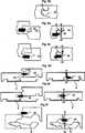
Zum mechanischen Verbinden von sowohl langen als auch kurzen Seiten in der vertikalen und horizontalen Richtung (Richtung D1, D2) werden mehrere Verfahren verwendet, aber die Arretierung erfolgt immer in 3 Schritten, wobei Anwinkeln oder Einrasten mit einer Verschiebung entlang der Verbindungskante in der arretierten Position kombiniert wird, nachdem eine optionale Seite verbunden worden ist.
- • Anwinkeln der langen Seite, Verschieben und Einrasten der kurzen Seite.
- • Einrasten der langen Seite, Verschieben und Einrasten der kurzen Seite.
- • Anwinkeln der kurzen Seite, Verschieben der neuen Platte entlang der kurzen Seitenkante der vorherigen Platte und schließlich Anwinkeln von zwei Platten nach unten.
- • Angling the long side, moving and snapping the short side.
- • Snap the long side into place, move and snap in the short side.
- • Angling the short side, moving the new plate along the short side edge of the previous plate and finally angling down two plates.
Diese Verlegungsverfahren können auch mit Einführen entlang der Verbindungskante kombiniert werden.These laying methods can also be combined with insertion along the joint edge.
Das Arretiersystem kann bekannterweise jedoch auch so ausgebildet sein, dass das Einrasten durch eine Bewegung erfolgen kann, die vertikal zur Oberfläche der Bodenplatte verläuft. Im Allgemeinen wird die lange Seite durch Anwinkeln und die kurze Seite durch ein vertikales Anwinkeln arretiert, wobei das Arretieren mit einem Einrastvorgang erfolgt. Ein derartiges System wird in der
Bodenplatten können bekannterweise an der langen und der kurzen Seite vertikal und horizontal mit einem einfachen vertikalen Klappvorgang arretiert werden (
Es ist eine Bodenplatte mit einer vertikalen Verbindung in der Form einer flexiblen Feder und einer Nut vorgesehen, wobei die Feder aus einem getrennten Material hergestellt und flexibel ist, so dass mindestens eine der Seiten der Bodenplatte durch eine parallel zur vertikalen Ebene verlaufende vertikale Bewegung verbunden werden kann.There is provided a bottom plate having a vertical connection in the form of a flexible spring and a groove, wherein the spring is made of a separate material and flexible, so that at least one of the sides of the bottom plate are connected by a vertical movement parallel to the vertical plane can.
Aus dieser Schrift geht auch hervor, wie ein Verbindungssystem mit einer flexiblen Feder hergestellt werden kann, die horizontal hinein- oder herausverschoben und/oder zusammengedrückt oder alternativ vertikal nach oben oder unten gebogen werden kann. In ihr wird eine getrennte Feder beispielsweise aus Holzfasermaterial beschrieben, die mittels eines flexiblen Materials wie beispielsweise Kautschukpaste horizontal verschoben werden kann. Es wird auch eine Ausführungsform mit einer Feder beschrieben, die einen federnden Innenteil hat.From this document it is also apparent how a connection system can be made with a flexible spring which can be moved in or out horizontally and / or compressed or alternatively bent vertically up or down. In her a separate spring, for example made of wood fiber material is described, which can be moved horizontally by means of a flexible material such as rubber paste. There is also described an embodiment with a spring having a resilient inner part.
Diese bekannte Technologie mit einer Feder, die sich während der Arretierung horizontal zu den benachbarten Kanten bewegt, hat im Vergleich zu den bekannten Installierungsverfahren mehrere Vorteile. Die Arretierung ist einfach und schneller, da 3 Schritte auf einen reduziert werden.This known technology with a spring that moves horizontally to the adjacent edges during locking has several advantages over the known installation methods. The lock is easy and faster as 3 steps are reduced to one.
Die in
Aus der
Kurze Darstellung der Erfindung und ihrer AufgabenBrief description of the invention and its objects
Eine erste übergreifende Aufgabe der vorliegenden Erfindung ist die Bereitstellung eines Bodenplattensatzes unter Verwendung eines Arretiersystems auf der Grundlage von vertikalem Abklappen mit einer flexiblen, in einer Nut verbundenen Feder. Mit dem Arretiersystem sollte es möglich sein, lediglich durch einen Anwinkelvorgang alle vier Seiten einer Platte vertikal und horizontal mit anderen Platten zu arretieren. Im Vergleich zum Stand der Technik sollten sich die Kosten und Funktionen als günstig erweisen. Ein wesentlicher Teil der übergreifenden Aufgabe ist die Verbesserung von Funktion und Kosten der Teile des Arretiersystems, die bewirken, dass sich die flexible Feder während des Arretierens verschiebt und in der arretierten Position zurückspringt.A first overarching object of the present invention is to provide a floorboard set using a vertical folding based locking system with a flexible spring connected in a groove. With the locking system, it should be possible to lock all four sides of a plate vertically and horizontally with other plates only by a Anwinkelvorgang. Compared to the prior art, the costs and functions should prove favorable. An essential part of the overarching objective is to improve the function and cost of the parts of the locking system that cause the flexible spring to shift during locking and spring back in the locked position.
Genauer besteht die Aufgabe in der Bereitstellung eines Bodenplattensatzes unter Verwendung eines Arretiersystems mit vertikalem Abklappen mit einer flexiblen Feder, bei dem einer oder mehrere der folgenden Vorteile erzielt werden.More specifically, the object is to provide a base plate set using a vertical folding locking system with a flexible spring, which achieves one or more of the following advantages.
Es sollte vorzugsweise möglich sein, die flexible Feder während des Arretierens mit so geringem Kraftaufwand zu verschieben, dass in Verbindung mit der Installierung keine Werkzeuge notwendig sind.It should preferably be possible to displace the flexible spring during locking with so little effort that no tools are necessary in connection with the installation.
Die Federwirkung sollte zuverlässig sein, und die flexible Feder sollte sich immer in ihre vorbestimmte Position zurückbewegen, wenn die Platten in die Position gebracht worden sind, in der sie arretiert werden sollen.The spring action should be reliable, and the flexible spring should always return to its predetermined position when the plates have been brought into the position in which they are to be locked.
Die vertikale Arretierung sollte fest sein und verhindern, dass sich zwei arretierte Platten vertikal bewegen, wenn sich die Feuchte ändert oder wenn der Fußboden begangen wird.The vertical locking should be firm and prevent two locked panels from moving vertically when the humidity changes or when the floor is closed.
Mit dem Arretiersystem sollte es möglich sein, Bodenplatten vertikal mit hoher Präzision zu arretieren, so dass die Oberflächen im Wesentlichen in einer Ebene sind.With the locking system, it should be possible to lock floor panels vertically with high precision, so that the surfaces are substantially in one plane.
Das vertikale Arretiersystem sollte so ausgelegt sein, dass die Material- und Produktionskosten niedrig sein könnten.The vertical locking system should be designed so that the material and production costs could be low.
Es sollte möglich sein, die separate flexible Feder einfach und kostengünstig mit der Bodenplatte zu verbinden. Dank der Verbindung sollte die flexible Feder während der Produktion, des Transports und der Installierung mit der Platte in Verbindung gehalten werden.It should be possible to easily and inexpensively connect the separate flexible spring to the bottom plate. Thanks to the connection, the flexible spring should be kept in contact with the plate during production, transport and installation.
Die obigen Aufgaben der Erfindung werden ganz oder zum Teil durch einen Bodenplattensatz nach dem unabhängigen Anspruch erfüllt. Ausführungsformen der Erfindung gehen aus den abhängigen Ansprüchen sowie aus der Beschreibung und den Zeichnungen hervor. The above objects of the invention are fully or partially met by a bottom plate set according to the independent claim. Embodiments of the invention will be apparent from the dependent claims, as well as from the description and drawings.
Es ist zwar vorteilhaft, die flexible Feder im Werk vor der Installierung in der Platte zu integrieren, aber die Erfindung schließt keine Ausführungsform aus, bei der flexible Federn als getrennte Komponenten geliefert werden, die vom Installierer vor der Installierung mit der Platte zu verbinden sind.While it is advantageous to integrate the flexible spring in the factory prior to installation in the panel, the invention does not preclude an embodiment in which flexible springs are provided as separate components to be connected by the installer to the panel prior to installation.
Die Erfindung gestattet horizontale und vertikale Arretierung aller Seiten von Bodenplatten durch einfaches Anwinkeln lediglich der langen Seiten. Daher eignet sie sich besonders für den Einsatz bei Platten, die in der arretierten Position schwer zu verschieben sind, weil sie beispielsweise lang sind, bei Platten, bei denen Teile des Arretiersystems aus einem Material mit hoher Reibung, wie beispielsweise Holz, hergestellt sind, und bei Arretiersystemen, die mit enger Passung, ohne Spiel oder sogar mit Vorspannung hergestellt sind. Insbesondere Platten mit einer derartigen Vorspannung, dass der Arretierstreifen in der arretierten Position gebogen ist und die Platten zusammendrückt, lassen sich nur sehr schwer verschieben. Das Arretiersystem, das ein vertikales Abklappen gestattet, verkürzt die Installierungsdauer solcher Platten beträchtlich.The invention allows horizontal and vertical locking of all sides of floor panels by simply angling only the long sides. Therefore, it is particularly suitable for use with plates that are difficult to move in the locked position, because they are long, for example, in plates in which parts of the locking system are made of a high friction material, such as wood, and Locking systems made with tight fit, no play or even preload. In particular, plates with such a bias that the locking strip is bent in the locked position and compresses the plates are very difficult to move. The locking system, which allows vertical folding, significantly shortens the installation time of such panels.
Die Erfindung eignet sich auch besonders gut für Platten, bei denen die lange Seite mit einer kurzen Seite verbunden wird, und für breite Platten, die beispielsweise breiter als 20 cm sind. Derartige Platten lassen sich nur schwer an der kurzen Seite einrasten, und bei den meisten Materialien müssen sie vertikal arretiert werden, um Höhenunterschiede zwischen den Verbindungsflächen zu vermeiden.The invention is also particularly well suited for plates in which the long side is joined with a short side, and for wide plates, for example wider than 20 cm. Such panels are difficult to latch on the short side, and for most materials, they must be locked vertically to avoid differences in height between the connection surfaces.
Kurze Beschreibung der ZeichnungenBrief description of the drawings
Es zeigen:Show it:
Beschreibung der Ausführungsformen der ErfindungDescription of the embodiments of the invention
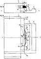
Unter Bezug auf
Unter Bezug auf
Die Vorderseiten
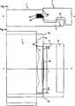
Zum Verbinden der beiden Verbindungskanten in den Richtungen D1 und D2 haben die Kanten der Bodenplatte auf an sich bekannte Weise einen Arretierstreifen
Das mechanische Arretiersystem umfasst eine getrennte flexible Feder
Bei dieser Ausführungsform könnte die Platte
Die flexible Feder
Die Verschiebungsnut
Die Federnut
Die flexible Feder
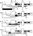
Eine präzise Passung zwischen den oberen Verbindungskanten könnte sogar mit Spiel erzielt werden. Die untere Federverschiebungsfläche
Ein erster bedeutender Vorteil besteht darin, dass die Feder aus recht starrem Material hergestellt werden könnte, das in der vertikalen Richtung fest und stabil ist, während gleichzeitig in der horizontalen Richtung D2 Flexibilität erzielt werden könnte. Die Biegeabschnitte könnten bedeutend größer ausgeführt werden als dies für die horizontale Verschiebung zur Erzielung der Arretierung notwendig wäre.A first significant advantage is that the spring could be made of a rather rigid material that is strong and stable in the vertical direction while at the same time providing flexibility in the horizontal direction D2. The bending sections could be made significantly larger than would be necessary for the horizontal displacement to achieve the lock.
Ein zweiter Vorteil besteht darin, dass die Teile, die flexibel sind und die erste und zweite horizontale Verschiebung erleichtern, auch die vertikale Stabilität der Feder unterstützen. Der Vorteil besteht darin, dass die Gesamtbreite TW der flexiblen Feder und die Tiefe der Verschiebungsnut recht begrenzt sein könnten. Das verbessert die Festigkeit und Feuchtigkeitsdeformierung der Verbindungskante. Als nicht einschränkendes Beispiel könnte die Gesamtbreite TW der flexiblen Feder ungefähr 5–15 mm betragen.A second advantage is that the parts, which are flexible and facilitate the first and second horizontal displacements, also support the vertical stability of the spring. The advantage is that the overall width TW of the flexible spring and the depth of the sliding groove could be quite limited. This improves the strength and moisture deformation of the joint edge. As a non-limiting example, the total width TW of the flexible spring could be about 5-15 mm.
Ein dritter Vorteil besteht darin, dass die flexible Feder einteilig aus einem einzigen Material hergestellt werden könnte, ohne weiche und komprimierbare Materialien. Dadurch verringern sich die Herstellungskosten und die Verbindung der Feder in der Verschiebungsnut wird erleichtert.A third advantage is that the flexible spring could be made in one piece from a single material, without soft and compressible materials. This reduces the manufacturing costs and the connection of the spring in the displacement groove is facilitated.
Die Verschiebungsnut bei dieser bevorzugten Ausführungsform ist eine durchgehende Nut über die gesamte Länge der Verbindungskante. Die Verschiebungsnut
Abmontieren ließe sich die Klappplatte mit einem nadelförmigen Werkzeug, das vom Eckabschnitt
Im Allgemeinen könnte jede Form eingesetzt werden, dank derer ein Teil der Feder in Längenrichtung gebogen werden und so zurückspringen könnte, dass der vorstehende Abschnitt um 0,1 mm oder mehr verschoben werden könnte. Normalerweise sollte die Verschiebung 1–3 mm betragen, aber sehr geringe Verschiebungen im Bereich von einigen 0,1 mm könnten zur Erzielung einer vertikalen Arretierung ausreichen, die besonders bei HDF-Material eine vertikale Bewegung verhindert.In general, any shape could be used that would allow part of the spring to be bent lengthwise and spring back so that the protruding portion could be displaced by 0.1 mm or more. Normally, the displacement should be 1-3 mm, but very small displacements in the range of a few 0.1 mm could be sufficient to achieve vertical locking, which prevents vertical movement, especially with HDF material.
Bei Bodenplatten mit einer Breite von ungefähr 20 cm reicht eine flexible Feder mit einer Länge von ein paar Zentimetern aus, wenn sie am mittleren Teil der kurzen Seite, ungefähr 6–9 cm vom Eckabschnitt entfernt positioniert ist.For floor panels approximately 20 cm wide, a flexible spring of a few centimeters in length is sufficient when positioned at the middle part of the short side, about 6-9 cm from the corner.
Die flexible Feder könnte auch aus einer einzigen Komponente hergestellt sein, wie bei der obigen Ausführungsform beschrieben, und mit einer Dicke von lediglich ungefähr 1 mm, und sie könnte zur Verbindung von bis zu 4 mm dünnen Fußbodenbrettern verwendet werden.The flexible spring could also be made from a single component, as described in the above embodiment, and with a thickness of only about 1 mm, and could be used to join up to 4 mm thin floorboards.
Das Verfahren zur Herstellung einer getrennten Feder, die in eine Nut eingeführt wird, könnte selbstverständlich verwendet werden, um Material zu sparen und die Reibeigenschaften zu verbessern, selbst wenn die Feder nicht flexibel oder verschiebbar ist. Die Verfahren und das Prinzip könnten auch zusammen mit einer flexiblen Feder verwendet werden, die sich während des Arretierens in einer vertikalen Richtung nach oben und/oder unten biegen lässt.The method of making a separate spring which is inserted into a groove could, of course, be used to save material and improve the friction properties even when the spring is not flexible or slidable. The methods and principle could also be used in conjunction with a flexible spring that flexes up and / or down in a vertical direction during locking.
Das System könnte verwendet werden, um an einer Wand installierte fliesenförmige Platten zu verbinden, und die Fliesen könnten miteinander und mit einem an der Wand befestigten Arretierelement verbunden werden.The system could be used to connect tile-like panels installed on a wall, and the tiles could be joined together and with a locking element attached to the wall.
Die flexible Feder kann ohne den Arretierstreifen verwendet werden, um lediglich ein vertikales Arretieren zu erzielen.The flexible spring can be used without the locking strip to achieve only a vertical locking.
Claims (7)
Translated fromGermanPriority Applications (1)
| Application Number | Priority Date | Filing Date | Title |
|---|---|---|---|
| DE602004010914TDE602004010914T3 (en) | 2004-10-22 | 2004-10-22 | Set of floor panels |
Applications Claiming Priority (2)
| Application Number | Priority Date | Filing Date | Title |
|---|---|---|---|
| EP04025167AEP1650375B2 (en) | 2004-10-22 | 2004-10-22 | A set of floor panels |
| DE602004010914TDE602004010914T3 (en) | 2004-10-22 | 2004-10-22 | Set of floor panels |
Publications (3)
| Publication Number | Publication Date |
|---|---|
| DE602004010914D1 DE602004010914D1 (en) | 2008-02-07 |
| DE602004010914T2 DE602004010914T2 (en) | 2008-12-11 |
| DE602004010914T3true DE602004010914T3 (en) | 2011-07-07 |
Family
ID=34927082
Family Applications (8)
| Application Number | Title | Priority Date | Filing Date |
|---|---|---|---|
| DE602004010914TExpired - LifetimeDE602004010914T3 (en) | 2004-10-22 | 2004-10-22 | Set of floor panels |
| DE202005021864UExpired - LifetimeDE202005021864U1 (en) | 2004-10-22 | 2005-10-21 | Mechanical locking of floor panels with a flexible spring |
| DE202005021702UExpired - LifetimeDE202005021702U1 (en) | 2004-10-22 | 2005-10-21 | Mechanical locking of floor panels with a flexible spring |
| DE202005022097UExpired - LifetimeDE202005022097U1 (en) | 2004-10-22 | 2005-10-21 | Mechanical locking of floor panels with a flexible spring |
| DE202005022095UExpired - LifetimeDE202005022095U1 (en) | 2004-10-22 | 2005-10-21 | Mechanical locking of floor panels with a flexible spring |
| DE202005021889UExpired - LifetimeDE202005021889U1 (en) | 2004-10-22 | 2005-10-21 | Device for providing floorboards with a flexible spring |
| DE202005022094UExpired - LifetimeDE202005022094U1 (en) | 2004-10-22 | 2005-10-21 | building slab |
| DE202005021865UExpired - LifetimeDE202005021865U1 (en) | 2004-10-22 | 2005-10-21 | Mechanical locking of floor panels with a flexible spring |
Family Applications After (7)
| Application Number | Title | Priority Date | Filing Date |
|---|---|---|---|
| DE202005021864UExpired - LifetimeDE202005021864U1 (en) | 2004-10-22 | 2005-10-21 | Mechanical locking of floor panels with a flexible spring |
| DE202005021702UExpired - LifetimeDE202005021702U1 (en) | 2004-10-22 | 2005-10-21 | Mechanical locking of floor panels with a flexible spring |
| DE202005022097UExpired - LifetimeDE202005022097U1 (en) | 2004-10-22 | 2005-10-21 | Mechanical locking of floor panels with a flexible spring |
| DE202005022095UExpired - LifetimeDE202005022095U1 (en) | 2004-10-22 | 2005-10-21 | Mechanical locking of floor panels with a flexible spring |
| DE202005021889UExpired - LifetimeDE202005021889U1 (en) | 2004-10-22 | 2005-10-21 | Device for providing floorboards with a flexible spring |
| DE202005022094UExpired - LifetimeDE202005022094U1 (en) | 2004-10-22 | 2005-10-21 | building slab |
| DE202005021865UExpired - LifetimeDE202005021865U1 (en) | 2004-10-22 | 2005-10-21 | Mechanical locking of floor panels with a flexible spring |
Country Status (28)
| Country | Link |
|---|---|
| US (7) | US8341915B2 (en) |
| EP (29) | EP1650375B2 (en) |
| JP (1) | JP4652411B2 (en) |
| KR (1) | KR101206400B1 (en) |
| CN (2) | CN100547206C (en) |
| AT (3) | ATE535660T1 (en) |
| AU (1) | AU2005296349B2 (en) |
| BR (1) | BRPI0516331B1 (en) |
| CA (1) | CA2581678C (en) |
| CY (1) | CY1107360T1 (en) |
| DE (8) | DE602004010914T3 (en) |
| DK (4) | DK1936068T3 (en) |
| ES (6) | ES2378330T3 (en) |
| HU (2) | HUE043159T2 (en) |
| IL (1) | IL182264A (en) |
| LT (3) | LT2388399T (en) |
| MX (1) | MX2007004786A (en) |
| MY (1) | MY139000A (en) |
| NO (1) | NO338585B1 (en) |
| NZ (1) | NZ554905A (en) |
| PL (11) | PL1936068T3 (en) |
| PT (5) | PT1650375E (en) |
| RU (1) | RU2373348C2 (en) |
| SI (3) | SI1650375T2 (en) |
| TR (4) | TR201901831T4 (en) |
| UA (1) | UA90282C2 (en) |
| WO (1) | WO2006043893A1 (en) |
| ZA (1) | ZA200704038B (en) |
Families Citing this family (383)
| Publication number | Priority date | Publication date | Assignee | Title |
|---|---|---|---|---|
| US7131242B2 (en) | 1995-03-07 | 2006-11-07 | Pergo (Europe) Ab | Flooring panel or wall panel and use thereof |
| SE9500810D0 (en) | 1995-03-07 | 1995-03-07 | Perstorp Flooring Ab | Floor tile |
| US7992358B2 (en) | 1998-02-04 | 2011-08-09 | Pergo AG | Guiding means at a joint |
| SE512290C2 (en) | 1998-06-03 | 2000-02-28 | Valinge Aluminium Ab | Locking system for mechanical joining of floorboards and floorboard provided with the locking system |
| SE514645C2 (en) | 1998-10-06 | 2001-03-26 | Perstorp Flooring Ab | Floor covering material comprising disc-shaped floor elements intended to be joined by separate joint profiles |
| SE517478C2 (en) | 1999-04-30 | 2002-06-11 | Valinge Aluminium Ab | Locking system for mechanical hoisting of floorboards, floorboard provided with the locking system and method for producing mechanically foldable floorboards |
| SE517183C2 (en) | 2000-01-24 | 2002-04-23 | Valinge Aluminium Ab | Locking system for mechanical joining of floorboards, floorboard provided with the locking system and method for making such floorboards |
| SE518184C2 (en) | 2000-03-31 | 2002-09-03 | Perstorp Flooring Ab | Floor covering material comprising disc-shaped floor elements which are joined together by means of interconnecting means |
| US8028486B2 (en) | 2001-07-27 | 2011-10-04 | Valinge Innovation Ab | Floor panel with sealing means |
| US8250825B2 (en) | 2001-09-20 | 2012-08-28 | Välinge Innovation AB | Flooring and method for laying and manufacturing the same |
| SE525661C2 (en) | 2002-03-20 | 2005-03-29 | Vaelinge Innovation Ab | Floor boards decorative joint portion making system, has surface layer with underlying layer such that adjoining edge with surface has underlying layer parallel to horizontal plane |
| ATE467015T1 (en)* | 2002-04-03 | 2010-05-15 | Vaelinge Innovation Ab | FLOOR PANEL WITH INTEGRATED CONNECTING MEANS AND METHOD FOR THE PRODUCTION THEREOF |
| US7739849B2 (en)* | 2002-04-22 | 2010-06-22 | Valinge Innovation Ab | Floorboards, flooring systems and methods for manufacturing and installation thereof |
| US20040206036A1 (en) | 2003-02-24 | 2004-10-21 | Valinge Aluminium Ab | Floorboard and method for manufacturing thereof |
| US7845140B2 (en) | 2003-03-06 | 2010-12-07 | Valinge Innovation Ab | Flooring and method for installation and manufacturing thereof |
| SE0300642D0 (en)* | 2003-03-11 | 2003-03-11 | Pergo Europ Ab | Process for sealing a joint |
| SE526688C2 (en) | 2003-11-20 | 2005-10-25 | Pergo Europ Ab | Method of joining panels where a locking rod is inserted into a locking groove or locking cavity |
| US7886497B2 (en) | 2003-12-02 | 2011-02-15 | Valinge Innovation Ab | Floorboard, system and method for forming a flooring, and a flooring formed thereof |
| US20050166516A1 (en) | 2004-01-13 | 2005-08-04 | Valinge Aluminium Ab | Floor covering and locking systems |
| SE527570C2 (en) | 2004-10-05 | 2006-04-11 | Vaelinge Innovation Ab | Device and method for surface treatment of sheet-shaped material and floor board |
| ES2378330T3 (en)* | 2004-10-22 | 2012-04-11 | Välinge Innovation AB | A method of providing floor panels with a mechanical locking system |
| US7454875B2 (en) | 2004-10-22 | 2008-11-25 | Valinge Aluminium Ab | Mechanical locking system for floor panels |
| US7841144B2 (en) | 2005-03-30 | 2010-11-30 | Valinge Innovation Ab | Mechanical locking system for panels and method of installing same |
| DE102004062648B4 (en)* | 2004-12-21 | 2006-09-07 | Kronotec Ag | Device for inserting springs in the front and / or long sides of technical wood products |
| US8215078B2 (en) | 2005-02-15 | 2012-07-10 | Välinge Innovation Belgium BVBA | Building panel with compressed edges and method of making same |
| BE1016938A6 (en) | 2005-03-31 | 2007-10-02 | Flooring Ind Ltd | Floor panel manufacturing method, involves providing panels at lower side with guiding groove and providing two opposite sides with profiled edge regions that comprise coupling parts |
| US20130139478A1 (en) | 2005-03-31 | 2013-06-06 | Flooring Industries Limited, Sarl | Methods for packaging floor panels, as well as packed set of floor panels |
| US8061104B2 (en) | 2005-05-20 | 2011-11-22 | Valinge Innovation Ab | Mechanical locking system for floor panels |
| SE529076C2 (en)* | 2005-07-11 | 2007-04-24 | Pergo Europ Ab | A joint for panels |
| US20070175144A1 (en) | 2006-01-11 | 2007-08-02 | Valinge Innovation Ab | V-groove |
| SE530653C2 (en) | 2006-01-12 | 2008-07-29 | Vaelinge Innovation Ab | Moisture-proof floor board and floor with an elastic surface layer including a decorative groove |
| DE102006011887A1 (en) | 2006-01-13 | 2007-07-19 | Akzenta Paneele + Profile Gmbh | Blocking element, panel with separate blocking element, method of installing a panel covering of panels with blocking elements, and method and device for pre-assembling a blocking element on a panel |
| DE102006006124A1 (en)* | 2006-02-10 | 2007-08-23 | Flooring Technologies Ltd. | Device for locking two building panels |
| BE1017157A3 (en) | 2006-06-02 | 2008-03-04 | Flooring Ind Ltd | FLOOR COVERING, FLOOR ELEMENT AND METHOD FOR MANUFACTURING FLOOR ELEMENTS. |
| SE533410C2 (en) | 2006-07-11 | 2010-09-14 | Vaelinge Innovation Ab | Floor panels with mechanical locking systems with a flexible and slidable tongue as well as heavy therefore |
| US7861482B2 (en) | 2006-07-14 | 2011-01-04 | Valinge Innovation Ab | Locking system comprising a combination lock for panels |
| SE531110C2 (en)* | 2006-07-14 | 2008-12-23 | Vaelinge Innovation Ab | Locking system comprising a combination lock for panels |
| DE102006037614B3 (en)* | 2006-08-10 | 2007-12-20 | Guido Schulte | Floor covering, has head spring pre-assembled in slot and protruding over end of slot, and wedge surface formed at slot or head spring such that head spring runs into wedge surface by shifting projecting end of head spring into slot |
| US8323016B2 (en) | 2006-09-15 | 2012-12-04 | Valinge Innovation Belgium Bvba | Device and method for compressing an edge of a building panel and a building panel with compressed edges |
| US8689512B2 (en) | 2006-11-15 | 2014-04-08 | Valinge Innovation Ab | Mechanical locking of floor panels with vertical folding |
| SE532607C2 (en)* | 2006-11-15 | 2010-03-02 | Vaelinge Innovation Ab | Mechanical locking of vertical paneling floor panels |
| PL2570565T3 (en)* | 2006-11-15 | 2019-05-31 | Vaelinge Innovation Ab | Mechanical locking of floor panels with vertical folding |
| US11725394B2 (en) | 2006-11-15 | 2023-08-15 | Välinge Innovation AB | Mechanical locking of floor panels with vertical folding |
| DE102006057491A1 (en)* | 2006-12-06 | 2008-06-12 | Akzenta Paneele + Profile Gmbh | Panel and flooring |
| SE531111C2 (en) | 2006-12-08 | 2008-12-23 | Vaelinge Innovation Ab | Mechanical locking of floor panels |
| DE202007000310U1 (en)* | 2007-01-03 | 2007-04-19 | Akzenta Paneele + Profile Gmbh | Panel for floor covering has vertical locking element with complementary hook elements that are configured so that connected panels can be unlocked from their hooked and vertically locked state |
| DE102007002590A1 (en)* | 2007-01-12 | 2008-07-31 | Akzenta Paneele + Profile Gmbh | Panel and flooring |
| DE102007020271A1 (en) | 2007-02-01 | 2008-08-07 | August Hipper | Floor panel connector, has catch lug extending over area of longitudinal edges or front sides of panel, and locking part formed by circumference wall of window, where locking lug or catch lug extends through locking part in locked condition |
| DE202007018998U1 (en) | 2007-02-21 | 2010-03-04 | Hamberger Industriewerke Gmbh | Connection for plate-shaped components |
| DE202007018662U1 (en) | 2007-03-26 | 2009-02-19 | Kronotec Ag | Panel, in particular floor panel |
| US20080236431A1 (en) | 2007-03-28 | 2008-10-02 | Pergo (Europe) Ab | Process for Color Variability in Printing to Simulate Color Variation of Natural Product |
| DE102007026342B4 (en)* | 2007-06-06 | 2013-11-28 | Laminatepark Gmbh & Co. Kg | Set of tabular panels with movable locking element |
| DE102007063837B3 (en) | 2007-06-06 | 2020-01-23 | Laminatepark Gmbh & Co. Kg | Set of panel-shaped panels with a movable locking element |
| DE102007032885B4 (en) | 2007-07-14 | 2016-01-14 | Flooring Technologies Ltd. | Panel, in particular floor panel and means for locking interconnected panels |
| DE102007049792A1 (en) | 2007-08-10 | 2009-02-19 | Hamberger Industriewerke Gmbh | connection |
| DE202008005295U1 (en) | 2007-08-10 | 2008-10-23 | Hamberger Industriewerke Gmbh | connection |
| DE102007042250B4 (en) | 2007-09-06 | 2010-04-22 | Flooring Technologies Ltd. | Device for connecting and locking two building panels, in particular floor panels |
| DE102007042840B4 (en)* | 2007-09-10 | 2010-04-22 | Flooring Technologies Ltd. | Panel, in particular floor panel |
| US8353140B2 (en) | 2007-11-07 | 2013-01-15 | Valinge Innovation Ab | Mechanical locking of floor panels with vertical snap folding |
| US8499521B2 (en) | 2007-11-07 | 2013-08-06 | Valinge Innovation Ab | Mechanical locking of floor panels with vertical snap folding and an installation method to connect such panels |
| PL2602077T3 (en) | 2007-11-19 | 2017-12-29 | Välinge Innovation AB | Recycling of laminate floorings |
| US9783996B2 (en) | 2007-11-19 | 2017-10-10 | Valinge Innovation Ab | Fibre based panels with a wear resistance surface |
| PL3072653T3 (en) | 2007-11-19 | 2022-08-22 | Välinge Innovation AB | Method of manufacturing a building panel |
| BE1018600A5 (en) | 2007-11-23 | 2011-04-05 | Flooring Ind Ltd Sarl | FLOOR PANEL. |
| DE102007062430B3 (en)* | 2007-12-20 | 2009-07-02 | Flooring Technologies Ltd. | Method for machining a side edge of a panel and apparatus for carrying out the method |
| DE102008003117B4 (en) | 2008-01-02 | 2011-01-27 | Flooring Technologies Ltd. | Device for locking two building panels |
| US20100285289A1 (en)* | 2008-01-09 | 2010-11-11 | Oke Nollet | Floor covering, formed from floor panels and method for manufacturing such floor panels |
| DE102008003550B4 (en) | 2008-01-09 | 2009-10-22 | Flooring Technologies Ltd. | Device and method for locking two floor panels |
| MY152779A (en) | 2008-01-31 | 2014-11-28 | Valinge Innovation Ab | Mechanical locking of floor panels, methods to install and uninstall panels, a method and an equipment to produce the locking system, a method to connect a displaceable tongue to a panel and a tongue blank |
| US8505257B2 (en) | 2008-01-31 | 2013-08-13 | Valinge Innovation Ab | Mechanical locking of floor panels |
| US8419877B2 (en) | 2008-04-07 | 2013-04-16 | Ceraloc Innovation Belgium Bvba | Wood fibre based panels with a thin surface layer |
| US11235565B2 (en) | 2008-04-07 | 2022-02-01 | Valinge Innovation Ab | Wood fibre based panels with a thin surface layer |
| US8112967B2 (en) | 2008-05-15 | 2012-02-14 | Valinge Innovation Ab | Mechanical locking of floor panels |
| DE102008030281B3 (en)* | 2008-06-30 | 2009-10-29 | Guido Schulte | Method for inserting spring into longitudinal or head-sided groove in element plate of floor covering, involves releasing springs from transition belt and shifting springs into groove in element plates for locking plates with one another |
| DE102008031167B4 (en)* | 2008-07-03 | 2015-07-09 | Flooring Technologies Ltd. | Method for connecting and locking glueless laying floor panels |
| DE202008011589U1 (en)* | 2008-09-01 | 2008-11-27 | Akzenta Paneele + Profile Gmbh | Plastic floor panel with mechanical locking edges |
| DE102008047098B3 (en)* | 2008-09-12 | 2010-04-08 | Guido Schulte | flooring |
| DE102008047099B4 (en)* | 2008-09-12 | 2010-05-12 | Guido Schulte | flooring |
| US20100221493A1 (en) | 2008-11-21 | 2010-09-02 | Mats Hintze | Use of silane-treated particles in laminates to improve clarity |
| EP2376722A1 (en) | 2008-12-16 | 2011-10-19 | HAMBERGER INDUSTRIEWERKE GmbH | Floor covering |
| BE1018389A3 (en) | 2008-12-17 | 2010-10-05 | Unilin Bvba | COMPOSITE ELEMENT, MULTI-LAYER PLATE AND PANEL-SHAPED ELEMENT FOR FORMING SUCH COMPOSITE ELEMENT. |
| US8316612B2 (en)* | 2008-12-18 | 2012-11-27 | Radva Corporation | Pre-insulated structural building panels |
| BE1018627A5 (en) | 2009-01-16 | 2011-05-03 | Flooring Ind Ltd Sarl | FLOOR PANEL. |
| WO2010087752A1 (en)* | 2009-01-30 | 2010-08-05 | Välinge Innovation Belgium BVBA | Mechanical lockings of floor panels and a tongue blank |
| PL2226447T3 (en)* | 2009-02-27 | 2012-10-31 | Vaelinge Innovation Ab | Panelling, in particular floor panelling |
| CH700513A2 (en)* | 2009-03-10 | 2010-09-15 | Innovaris Ag | Panels. |
| DE102009013472A1 (en) | 2009-03-19 | 2010-09-23 | Wemhöner Systems Technologies AG | Method for inserting spring into groove at side edge of floor covering, involves engaging free spring end by squeezing unit that is arranged laterally in conveying path and squeezed into groove |
| EP2236694A1 (en)* | 2009-03-25 | 2010-10-06 | Spanolux N.V.- DIV. Balterio | A fastening system and a panel |
| DE102009016520A1 (en) | 2009-04-08 | 2010-10-28 | Hamberger Industriewerke Gmbh | Panel and process for its production |
| BE1018728A3 (en) | 2009-04-22 | 2011-07-05 | Flooring Ind Ltd Sarl | FLOOR PANEL. |
| EP2270291B1 (en) | 2009-06-08 | 2011-05-18 | Flooring Technologies Ltd. | Set of building panels with device for locking two of these panels |
| NL2003019C2 (en)* | 2009-06-12 | 2010-12-15 | 4Sight Innovation Bv | FLOOR PANEL AND FLOOR COVERAGE CONSISING OF MULTIPLE OF SUCH FLOOR PANELS. |
| BE1018802A3 (en)* | 2009-06-29 | 2011-09-06 | Flooring Ind Ltd Sarl | PANEL, MORE SPECIAL FLOOR PANEL. |
| DE102009034902B4 (en)* | 2009-07-27 | 2015-10-01 | Guido Schulte | Surface made of mechanically interconnectable panels |
| DE102009034903B3 (en)* | 2009-07-27 | 2011-01-20 | Guido Schulte | Surface made of mechanically interconnectable panels |
| CN102574292B (en) | 2009-07-31 | 2016-05-18 | 瓦林格创新股份有限公司 | Process relevant method and apparatus to the edge of building panelling |
| US11717901B2 (en) | 2009-07-31 | 2023-08-08 | Valinge Innovation Ab | Methods and arrangements relating to edge machining of building panels |
| US8931174B2 (en) | 2009-07-31 | 2015-01-13 | Valinge Innovation Ab | Methods and arrangements relating to edge machining of building panels |
| US8365499B2 (en) | 2009-09-04 | 2013-02-05 | Valinge Innovation Ab | Resilient floor |
| PL2473687T3 (en) | 2009-09-04 | 2019-10-31 | Vaelinge Innovation Ab | A method of assembling resilient floorboards which are provided with a mechanical locking system |
| US11725395B2 (en) | 2009-09-04 | 2023-08-15 | Välinge Innovation AB | Resilient floor |
| DE102009041297B4 (en)* | 2009-09-15 | 2018-10-11 | Guido Schulte | Coating of mechanically interconnectable elements and a process for the production of elements |
| DE102009046689A1 (en)* | 2009-11-13 | 2011-05-19 | Peri Gmbh | An element |
| BE1019008A3 (en) | 2009-11-20 | 2011-12-06 | Flooring Ind Ltd Sarl | FLOOR PANEL. |
| BR112012013809B1 (en) | 2009-12-17 | 2019-07-30 | Välinge Innovation AB | METHOD FOR MANUFACTURING FLOOR PANELS |
| PT2339092T (en) | 2009-12-22 | 2019-07-19 | Flooring Ind Ltd Sarl | Method for producing covering panels |
| PL4092213T3 (en) | 2010-01-11 | 2024-03-25 | Välinge Innovation AB | Floor covering with interlocking design |
| BR112012016569A2 (en) | 2010-01-12 | 2016-04-05 | Vaelinge Innovation Ab | mechanical locking system for floor panels |
| BR112012017589B1 (en) | 2010-01-14 | 2019-11-12 | Spanolux N V Div Balterio | floor panel mounting |
| PL2523805T3 (en) | 2010-01-15 | 2018-06-29 | Välinge Innovation AB | Fibre based panels with a decorative wear resistance surface |
| EP2523808A4 (en) | 2010-01-15 | 2017-01-04 | Välinge Innovation AB | Fibre based panels with a decorative wear resistance surface |
| MX2012007874A (en) | 2010-01-15 | 2012-08-03 | Ceraloc Innovation Belgium | Bright colored surface layer. |
| US20110177319A1 (en) | 2010-01-15 | 2011-07-21 | Valinge Innovation Belgium Bvba | Heat and pressure generated design |
| DE102010004717A1 (en) | 2010-01-15 | 2011-07-21 | Pergo (Europe) Ab | Set of panels comprising retaining profiles with a separate clip and method for introducing the clip |
| US8234830B2 (en) | 2010-02-04 | 2012-08-07 | Välinge Innovations AB | Mechanical locking system for floor panels |
| CA2786680C (en) | 2010-02-04 | 2018-06-12 | Vaelinge Innovation Ab | Mechanical locking system for floor panels and a tongue therefore |
| CN102199944A (en)* | 2010-03-26 | 2011-09-28 | 何其佳 | Architectural decorative plate and flexible false tongue used for connection of architectural decorative plates |
| US10899166B2 (en) | 2010-04-13 | 2021-01-26 | Valinge Innovation Ab | Digitally injected designs in powder surfaces |
| US8480841B2 (en) | 2010-04-13 | 2013-07-09 | Ceralog Innovation Belgium BVBA | Powder overlay |
| CN102844506B (en) | 2010-04-15 | 2015-08-12 | 巴尔特利奥-斯巴诺吕克斯股份公司 | floor components |
| BE1019331A5 (en) | 2010-05-10 | 2012-06-05 | Flooring Ind Ltd Sarl | FLOOR PANEL AND METHODS FOR MANUFACTURING FLOOR PANELS. |
| BE1019501A5 (en) | 2010-05-10 | 2012-08-07 | Flooring Ind Ltd Sarl | FLOOR PANEL AND METHOD FOR MANUFACTURING FLOOR PANELS. |
| CN104831904B (en)* | 2010-05-10 | 2017-05-24 | 佩尔戈(欧洲)股份公司 | Set of panels |
| DE102010021436A1 (en) | 2010-05-25 | 2011-12-01 | Hamberger Industriewerke Gmbh | Connection for two panels |
| US20110293904A1 (en) | 2010-05-27 | 2011-12-01 | Pergo AG | Method for manufacturing a surface element |
| US10315219B2 (en) | 2010-05-31 | 2019-06-11 | Valinge Innovation Ab | Method of manufacturing a panel |
| EP2575542B1 (en) | 2010-06-03 | 2021-03-10 | Unilin, BV | Composed element and corner connection applied herewith |
| US20130097959A1 (en) | 2010-06-30 | 2013-04-25 | Kreafin Group Sa | Panel With Improved Coupling Means |
| DE102011000013A1 (en) | 2010-08-04 | 2012-02-09 | Hamberger Industriewerke Gmbh | Surface elastic floor and mounting module |
| DE102010047752A1 (en) | 2010-10-08 | 2012-04-12 | Pergo AG | cover assembly |
| US8591696B2 (en) | 2010-11-17 | 2013-11-26 | Pergo (Europe) Ab | Method for manufacturing a surface element |
| DE102010063976B4 (en)* | 2010-12-22 | 2013-01-17 | Akzenta Paneele + Profile Gmbh | paneling |
| CN102619323A (en)* | 2011-01-27 | 2012-08-01 | 张国平 | Plastic material barb type lock floor |
| DE102011000546B4 (en)* | 2011-02-07 | 2016-03-24 | Fabian von Ferrari | Connection system, in particular for furniture |
| US8806832B2 (en) | 2011-03-18 | 2014-08-19 | Inotec Global Limited | Vertical joint system and associated surface covering system |
| WO2012141651A1 (en) | 2011-04-12 | 2012-10-18 | Ceraloc Innovation Belgium Bvba | Method of manufacturing a layer |
| MX342546B (en) | 2011-04-12 | 2016-10-03 | Vaelinge Innovation Ab | POWDER COMPENSATOR COAT. |
| MX352832B (en) | 2011-04-12 | 2017-12-08 | Vaelinge Innovation Ab | A powder mix and a method for producing a building panel. |
| ES2805332T3 (en) | 2011-04-12 | 2021-02-11 | Vaelinge Innovation Ab | Manufacturing method of a building panel |
| US9010067B2 (en)* | 2011-04-14 | 2015-04-21 | Geoffrey Alan Baker | Fabricating the locking steps in the groove element of spring-loaded split-tongue locking connector system |
| CA2831349C (en)* | 2011-04-15 | 2017-12-19 | i-TeConsult n.v | Surface covering kit comprising panels and an extraneous locking element |
| PL2520737T3 (en)* | 2011-05-03 | 2017-08-31 | Barlinek S.A. | Construction panel with a device for connection with at least one further construction panel on a base |
| UA109938C2 (en) | 2011-05-06 | 2015-10-26 | MECHANICAL LOCKING SYSTEM FOR CONSTRUCTION PANELS | |
| BE1020044A5 (en) | 2011-06-29 | 2013-04-02 | Unilin Bvba | TRAY, TRAY CONSTRUCTION AND METHOD FOR MANUFACTURING A TRAY. |
| UA114715C2 (en)* | 2011-07-05 | 2017-07-25 | Сералок Інновейшн Аб | Mechanical locking of floor panels with a glued tongue |
| US9725912B2 (en) | 2011-07-11 | 2017-08-08 | Ceraloc Innovation Ab | Mechanical locking system for floor panels |
| RU2603987C2 (en)* | 2011-07-11 | 2016-12-10 | Сералок Инновейшн Аб | Mechanical locking system for floor panels |
| US8650826B2 (en) | 2011-07-19 | 2014-02-18 | Valinge Flooring Technology Ab | Mechanical locking system for floor panels |
| HUE030211T2 (en)* | 2011-07-19 | 2017-04-28 | Ceraloc Innovation Ab | Mechanical locking system for building elements |
| DE102012105793A1 (en) | 2011-07-29 | 2013-01-31 | Hamberger Industriewerke Gmbh | Connection for elastic or plate-shaped components and floor covering |
| DE102012102339A1 (en) | 2011-07-29 | 2013-01-31 | Hamberger Industriewerke Gmbh | Connection for elastic or plate-shaped components, profile slides and floor coverings |
| DE102011052335B4 (en)* | 2011-08-01 | 2015-09-17 | Guido Schulte | Cover made of mechanically interconnectable panels and method for producing such panels |
| US8857126B2 (en) | 2011-08-15 | 2014-10-14 | Valinge Flooring Technology Ab | Mechanical locking system for floor panels |
| US8769905B2 (en) | 2011-08-15 | 2014-07-08 | Valinge Flooring Technology Ab | Mechanical locking system for floor panels |
| US8763340B2 (en)* | 2011-08-15 | 2014-07-01 | Valinge Flooring Technology Ab | Mechanical locking system for floor panels |
| UA110987C2 (en)* | 2011-08-15 | 2016-03-10 | Велінге Флорінг Текнолоджи Аб | Mechanical interlock system for floor panels |
| CN103748298B (en)* | 2011-08-15 | 2016-08-17 | 塞拉洛克创新股份有限公司 | Mechanical locking system for floor panels |
| HRP20171787T1 (en) | 2011-08-26 | 2017-12-29 | Ceraloc Innovation Ab | PANEL COAT |
| JP6105587B2 (en) | 2011-08-29 | 2017-04-05 | セラロック、イノベーション、アクチボラグ | Mechanical locking system for floor panels |
| CN102312885A (en)* | 2011-09-28 | 2012-01-11 | 北京安德固脚手架工程有限公司 | Splicing joint structure of strip plates |
| EP2763850B1 (en) | 2011-10-03 | 2018-07-18 | Unilin, BVBA | Floor panel |
| DE202011108752U1 (en)* | 2011-12-06 | 2012-01-24 | Akzenta Paneele + Profile Gmbh | Locking system for panels and panel with locking system |
| DE102011056494A1 (en) | 2011-12-15 | 2013-06-20 | Pergo (Europe) Ab | Set of panels with clip |
| CN103182122B (en)* | 2011-12-30 | 2016-03-02 | 北京谊安医疗系统股份有限公司 | For the locking device of fixing first aid type respirator |
| BE1020433A3 (en) | 2012-01-05 | 2013-10-01 | Flooring Ind Ltd Sarl | PANEL. |
| WO2013102804A2 (en) | 2012-01-05 | 2013-07-11 | Flooring Industries Limited, Sarl | Panel |
| BE1022209B1 (en)* | 2012-01-12 | 2016-03-01 | I.V.C. N.V. | FLOOR PANEL |
| US8935899B2 (en) | 2012-02-02 | 2015-01-20 | Valinge Innovation Ab | Lamella core and a method for producing it |
| EP2812510B1 (en) | 2012-02-07 | 2018-03-07 | Flooring Industries Limited, SARL | Floor panel for forming a floor covering, floor covering formed from such floor panels and method for manufacturing such floor panels |
| US8920876B2 (en) | 2012-03-19 | 2014-12-30 | Valinge Innovation Ab | Method for producing a building panel |
| EP2644802B1 (en) | 2012-03-28 | 2019-08-28 | Tarkett GDL | Substrate-free surface covering having coupling means |
| ES2639512T3 (en) | 2012-04-04 | 2017-10-26 | Välinge Innovation AB | Construction panel with a mechanical locking system |
| US8596013B2 (en) | 2012-04-04 | 2013-12-03 | Valinge Innovation Ab | Building panel with a mechanical locking system |
| US9216541B2 (en) | 2012-04-04 | 2015-12-22 | Valinge Innovation Ab | Method for producing a mechanical locking system for building panels |
| US8875464B2 (en) | 2012-04-26 | 2014-11-04 | Valinge Innovation Ab | Building panels of solid wood |
| PL2872711T3 (en) | 2012-05-08 | 2022-02-21 | Ab Gustaf Kähr | Floor panel |
| EP2662192B1 (en) | 2012-05-08 | 2017-07-12 | Ab Gustaf Kähr | Floor panel and method of its production |
| EP2664730A1 (en) | 2012-05-15 | 2013-11-20 | Falquon GmbH | Panel for laying in an area as cladding or lining with improved moisture resistance |
| CN104582916A (en) | 2012-06-19 | 2015-04-29 | 瓦林格创新股份有限公司 | Method for dividing a panel into a first panel and a second panel, method of forming a mechanical locking system for locking the first and second panels, and building panels |
| US9140010B2 (en) | 2012-07-02 | 2015-09-22 | Valinge Flooring Technology Ab | Panel forming |
| EP3511485A1 (en) | 2012-07-02 | 2019-07-17 | Ceraloc Innovation AB | Floor panels with reduced weight and material content |
| DE202012007012U1 (en) | 2012-07-19 | 2012-09-07 | Välinge Flooring Technology AB | Mechanical locking system for building panels, in particular floor panels |
| DE102012015359A1 (en)* | 2012-08-06 | 2014-02-06 | Thomas Lewtschanyn | Laminate, which is produced by direct lamination, useful as a rotor blade for wind power generation or as heat- and noise insulation in the automotive industry |
| US8993049B2 (en) | 2012-08-09 | 2015-03-31 | Valinge Flooring Technology Ab | Single layer scattering of powder surfaces |
| CN104870726B (en) | 2012-09-19 | 2017-11-07 | 依诺泰克环球有限公司 | Facing sheet and related latching system |
| PL2923012T3 (en) | 2012-11-22 | 2020-04-30 | Ceraloc Innovation Ab | Mechanical locking system for floor panels |
| US9181698B2 (en) | 2013-01-11 | 2015-11-10 | Valinge Innovation Ab | Method of producing a building panel and a building panel |
| EA039386B1 (en)* | 2013-01-11 | 2022-01-21 | Велинге Инновейшн Аб | Set of building panels |
| WO2014108875A1 (en)* | 2013-01-11 | 2014-07-17 | Flooring Industries Limited, Sarl | Floor panel for forming a floor covering, floor covering formed of such floor panels and method for manufacturing such floor panels |
| US9422713B2 (en)* | 2013-03-06 | 2016-08-23 | Jesse B. Trebil | In-situ fabricated wall framing and insulating system |
| US9194134B2 (en) | 2013-03-08 | 2015-11-24 | Valinge Innovation Ab | Building panels provided with a mechanical locking system |
| EA201992325A1 (en) | 2013-03-25 | 2020-05-31 | Велинге Инновейшн Аб | FLOOR PANELS EQUIPPED WITH MECHANICAL FIXING SYSTEM AND METHOD FOR PRODUCING SUCH FIXING SYSTEM |
| BE1021833B1 (en) | 2013-05-30 | 2016-01-21 | Flooring Industries Limited Sarl | PANEL |
| PT3014034T (en)* | 2013-06-27 | 2019-11-29 | Vaelinge Innovation Ab | Building panel with a mechanical locking system |
| UA118967C2 (en) | 2013-07-02 | 2019-04-10 | Велінге Інновейшн Аб | A METHOD OF MANUFACTURING A BUILDING PANEL AND A BUILDING PANEL |
| CN108118859A (en) | 2013-07-09 | 2018-06-05 | 塞拉洛克创新股份有限公司 | For the mechanical locking system of floor panel |
| BR112016003022B1 (en) | 2013-08-27 | 2021-08-17 | Vãlinge Innovation Ab | METHOD FOR PRODUCING A SEMI-PRODUCT FOR A BUILDING PANEL |
| CN103485512B (en)* | 2013-09-09 | 2015-09-23 | 浙江长兴森大竹木制品有限公司 | Wooden floor |
| CN103452292A (en)* | 2013-09-16 | 2013-12-18 | 肇庆鑫盈装饰材料有限公司 | Novel wood grain aluminum floor structure |
| US9726210B2 (en) | 2013-09-16 | 2017-08-08 | Valinge Innovation Ab | Assembled product and a method of assembling the product |
| CN109854597B (en) | 2013-09-16 | 2021-03-19 | 瓦林格创新股份有限公司 | Combination product and method for assembling the same |
| US10513094B2 (en) | 2013-10-18 | 2019-12-24 | Valinge Innovation Ab | Method of manufacturing a building panel |
| KR102314032B1 (en) | 2013-10-25 | 2021-10-15 | 세라록 이노베이션 에이비 | Mechanical locking system for floor panels |
| WO2015070890A1 (en)* | 2013-11-12 | 2015-05-21 | Grigorij Wagner | Flooring component |
| DE102013113109A1 (en) | 2013-11-27 | 2015-06-11 | Guido Schulte | floorboard |
| DE102013113130B4 (en) | 2013-11-27 | 2022-01-27 | Välinge Innovation AB | Method of manufacturing a floorboard |
| DE102013113125A1 (en) | 2013-11-27 | 2015-05-28 | Guido Schulte | Floor, wall or ceiling panel and method of making the same |
| DE102013225358A1 (en)* | 2013-12-10 | 2015-06-11 | Laminatepark Gmbh & Co. Kg | Panel with locking element |
| EP4390008A3 (en) | 2014-01-09 | 2024-09-04 | Unilin, BV | Floor panel for forming a floor covering |
| US9714672B2 (en) | 2014-01-10 | 2017-07-25 | Valinge Innovation Ab | Panels comprising a mechanical locking device and an assembled product comprising the panels |
| MX376334B (en) | 2014-01-10 | 2025-03-07 | Vaelinge Innovation Ab | FURNITURE BOARD. |
| MY175150A (en)* | 2014-01-10 | 2020-06-11 | Valinge Innovation Ab | Panels comprising a mechanical locking device and an assembled product comprising the panels |
| MY177553A (en) | 2014-01-10 | 2020-09-18 | Valinge Innovation Ab | Wood fibre based panel with a surface layer |
| US9260870B2 (en) | 2014-03-24 | 2016-02-16 | Ivc N.V. | Set of mutually lockable panels |
| EP3122958B1 (en) | 2014-03-24 | 2022-01-26 | Flooring Industries Limited, SARL | A set of mutually lockable panels |
| CN106103096B (en) | 2014-03-31 | 2018-08-24 | 塞拉洛克创新股份有限公司 | Composite panels and panels |
| ES2822958T3 (en)* | 2014-04-10 | 2021-05-05 | Berryalloc Nv | Floor board with universal connection system |
| DE102014106492A1 (en)* | 2014-05-08 | 2015-11-12 | Akzenta Paneele + Profile Gmbh | paneling |
| EP3851684A1 (en) | 2014-05-09 | 2021-07-21 | Välinge Innovation AB | Mechanical locking system for building panels |
| CN106457781A (en) | 2014-05-12 | 2017-02-22 | 瓦林格创新股份有限公司 | A method of producing a veneered element and such a veneered element |
| US10246883B2 (en) | 2014-05-14 | 2019-04-02 | Valinge Innovation Ab | Building panel with a mechanical locking system |
| CN106460394B (en)* | 2014-05-14 | 2019-09-17 | 瓦林格创新股份有限公司 | Building panel with mechanical locking system |
| BE1021929B1 (en) | 2014-07-04 | 2016-01-27 | Unilin Bvba | FLOOR PANEL |
| BR112016029151A2 (en) | 2014-07-11 | 2017-08-22 | Vaelinge Innovation Ab | panel with a slider |
| PT3169532T (en) | 2014-07-16 | 2023-10-27 | Vaelinge Innovation Ab | Method to produce a thermoplastic wear resistant foil |
| US11091917B2 (en) | 2014-08-27 | 2021-08-17 | James Hardie Technology Limited | Cladding element |
| US9752328B2 (en) | 2014-08-27 | 2017-09-05 | James Hardie Technology Limited | Cladding element |
| EP3186459B1 (en) | 2014-08-29 | 2019-06-26 | Välinge Innovation AB | Vertical joint system for a surface covering panel |
| DE102014112527A1 (en)* | 2014-09-01 | 2016-03-03 | Guido Schulte | Mechanical connection for panels and method for mounting a locking spring in a panel |
| DE102014112529A1 (en)* | 2014-09-01 | 2016-03-03 | Guido Schulte | Mechanical connection for panels and method for mounting a locking spring in a panel |
| CN105442831B (en)* | 2014-09-25 | 2018-05-04 | 能诚集团有限公司 | A kind of oblique angle tongue and groove building template |
| JP6377484B2 (en)* | 2014-10-07 | 2018-08-22 | 松原産業株式会社 | Flooring base material for assembly |
| JP6900313B2 (en) | 2014-11-27 | 2021-07-07 | ベーリンゲ、イノベイション、アクチボラグVaelinge Innovation Ab | Mechanical locking system for floor panels |
| ES2758673T3 (en) | 2014-12-19 | 2020-05-06 | Vaelinge Innovation Ab | Panels comprising a mechanical locking device |
| BR112017012681B1 (en) | 2014-12-22 | 2022-05-03 | Ceraloc Innovation Ab | Set of essentially identical floor panels |
| WO2016114712A1 (en) | 2015-01-16 | 2016-07-21 | Ceraloc Innovation Ab | Mechanical locking system for floor panels |
| DE202015101572U1 (en) | 2015-03-27 | 2015-04-21 | Guido Schulte | Coating of composite rectangular or square panels |
| CN104895263B (en)* | 2015-03-28 | 2017-05-10 | 渤海大学 | Decorative wall panel and decorative wall |
| EP3285620A4 (en) | 2015-04-21 | 2018-11-14 | Välinge Innovation AB | Panel with a slider |
| KR20170141223A (en)* | 2015-04-30 | 2017-12-22 | 뵈린게 이노베이션 에이비이 | A panel having a fastening device |
| DE202016009050U1 (en) | 2015-05-12 | 2021-10-07 | Aladdin Manufacturing Corporation | Floor board |
| WO2016204681A1 (en) | 2015-06-16 | 2016-12-22 | Välinge Innovation AB | A method of forming a building panel or surface element and such a building panel and surface element |
| TWM512880U (en)* | 2015-07-03 | 2015-11-21 | Fivetech Technology Inc | Lateral positioning device |
| CN104895291A (en)* | 2015-07-03 | 2015-09-09 | 大亚(江苏)地板有限公司 | Floorboard interlock |
| US10267038B2 (en) | 2015-09-03 | 2019-04-23 | Awi Licensing Llc | Ceiling system |
| BE1023446B1 (en) | 2015-09-14 | 2017-03-22 | Ivc N.V. | Method for manufacturing floor panels and floor panel for forming a floor covering |
| UA125554C2 (en) | 2015-09-22 | 2022-04-20 | Велінге Інновейшн Аб | Panels comprising a mechanical locking device and an assembled product comprising the panels |
| BE1023545B1 (en) | 2015-10-23 | 2017-04-28 | Flooring Industries Limited, Sarl | Set of floor panels for forming a floor covering |
| MX2018006522A (en) | 2015-12-03 | 2018-11-29 | Vaelinge Innovation Ab | Panels comprising a mechanical locking device and an assembled product comprising the panels. |
| US11267119B2 (en) | 2015-12-14 | 2022-03-08 | Milwaukee Electric Tool Corporation | Storage device system |
| CA3008157C (en)* | 2015-12-17 | 2023-08-22 | Valinge Innovation Ab | A method for producing a mechanical locking system for panels |
| BE1023817B1 (en) | 2016-01-15 | 2017-08-01 | Unilin Bvba | Floor panel for forming a floor covering, and substrate for a panel |
| DE102016114226A1 (en) | 2016-01-22 | 2017-07-27 | Hamberger Industriewerke Gmbh | Connection for elastic or solid components |
| DE102016114221A1 (en) | 2016-01-22 | 2017-07-27 | Hamberger Industriewerke Gmbh | Connection for components |
| EP3407765B1 (en)* | 2016-01-26 | 2021-03-03 | Välinge Innovation AB | Panels comprising a mechanical locking device to obtain a furniture product |
| KR20180109957A (en) | 2016-02-04 | 2018-10-08 | 뵈린게 이노베이션 에이비이 | Set of panels for assembled products |
| CA3011703A1 (en) | 2016-02-09 | 2017-08-17 | Valinge Innovation Ab | Element and method for providing dismantling groove |
| US10415613B2 (en) | 2016-02-09 | 2019-09-17 | Valinge Innovation Ab | Set of panel-shaped elements for a composed element |
| JP6921834B2 (en) | 2016-02-15 | 2021-08-18 | ベーリンゲ、イノベイション、アクチボラグVaelinge Innovation Ab | How to form panels for furniture products |
| US10828881B2 (en) | 2016-04-25 | 2020-11-10 | Valinge Innovation Ab | Veneered element and method of producing such a veneered element |
| WO2017187298A2 (en)* | 2016-04-25 | 2017-11-02 | Flooring Industries Limited, Sarl | Set of floor panels and method for installing this set of floor panels |
| BE1024157B1 (en) | 2016-04-25 | 2017-11-24 | Flooring Industries Limited, Sarl | Set of floor panels and method for installing this set of floor panels. |
| CA3108189C (en) | 2016-05-02 | 2022-08-23 | Keter Plastic Ltd. | Utility assembly and coupling mechanism |
| CN105966721B (en)* | 2016-06-28 | 2018-07-06 | 成都市天仁自动化科技有限公司 | Metal plate connection structure and liquid nitrogen container carry cylinder |
| BR112018076069B1 (en) | 2016-06-29 | 2023-01-17 | Vãlinge Innovation Ab | METHOD AND DEVICE FOR INSERTING A TAG |
| MY193272A (en)* | 2016-06-29 | 2022-09-29 | Valinge Innovation Ab | Method and device for inserting a tongue |
| WO2018004440A1 (en)* | 2016-06-29 | 2018-01-04 | Välinge Innovation AB | A method and device for managing and separating a tongue from a tongue blank |
| CN109311179B (en)* | 2016-06-30 | 2021-09-17 | 瓦林格创新股份有限公司 | Device for inserting a tongue |
| US10815660B2 (en) | 2016-09-16 | 2020-10-27 | Osblock Inc. | Structural panel assembly for mounting building walls and method for mounting building walls using same |
| AU2017335148B2 (en) | 2016-09-30 | 2023-04-20 | Välinge Innovation AB | Set of panels assembled by vertical displacement and locked together in the vertical and horizontal direction |
| CN117703894A (en) | 2016-10-27 | 2024-03-15 | 瓦林格创新股份有限公司 | Panel assembly with mechanical locking means |
| BE1024723B1 (en) | 2016-11-10 | 2018-06-11 | Ivc Bvba | Floor panel and method for manufacturing a floor panel. |
| DK3558609T3 (en) | 2016-12-22 | 2022-01-03 | Vaelinge Innovation Ab | DEVICE FOR INSERTING A FER IN AN INSERTING NOTICE IN A PANEL |
| CN113356508A (en)* | 2017-03-21 | 2021-09-07 | 地板工业有限公司 | Panel panel |
| NL2018781B1 (en) | 2017-04-26 | 2018-11-05 | Innovations4Flooring Holding N V | Panel and covering |
| HRP20230089T1 (en) | 2017-05-15 | 2023-03-17 | Välinge Innovation AB | Elements and a locking device for an assembled product |
| WO2018213560A1 (en) | 2017-05-17 | 2018-11-22 | Milwaukee Electric Tool Corporation | Storage device system |
| NL2018970B1 (en)* | 2017-05-23 | 2018-12-04 | Innovations 4 Flooring Holding Nv | Multi-purpose tile system |
| FR3068091B1 (en)* | 2017-06-23 | 2019-07-19 | Airbus Operations (S.A.S.) | HOLDING SYSTEM HAVING DECAL APPENDICES ANGULARLY |
| JP6635091B2 (en)* | 2017-06-30 | 2020-01-22 | 凸版印刷株式会社 | Flooring |
| UA125235C2 (en) | 2017-07-18 | 2022-02-02 | Зайло Текнолоджіз Аґ | PANELS WITH REMOVABLE EMBROIDERED EDGE FOR WALL, CEILING OR FLOOR COVERINGS |
| WO2019028041A1 (en) | 2017-07-31 | 2019-02-07 | Milwaukee Electric Tool Corporation | STORAGE DEVICE SYSTEM |
| USD896517S1 (en) | 2017-08-09 | 2020-09-22 | Keter Plastic Ltd. | Tool box |
| US11261893B2 (en) | 2017-08-15 | 2022-03-01 | National Nail Corp. | Hidden fastener unit and related method of use |
| US11898357B2 (en) | 2017-08-15 | 2024-02-13 | National Nail Corp. | Hidden fastener unit and related method of use |
| USD924044S1 (en) | 2019-11-20 | 2021-07-06 | National Nail Corp. | Fastener positioning device |
| USD945870S1 (en) | 2020-11-17 | 2022-03-15 | National Nail Corp. | Fastener positioning device |
| US11149445B2 (en) | 2017-08-15 | 2021-10-19 | National Nail Corp. | Hidden fastener unit and related method of use |
| US12234654B2 (en) | 2017-08-15 | 2025-02-25 | National Nail Corp. | Hidden fastener unit and related method of use |
| US11111679B2 (en) | 2017-08-15 | 2021-09-07 | National Nail Corp. | Hidden fastener unit and related method of use |
| USD850897S1 (en) | 2018-05-18 | 2019-06-11 | National Nail Corp. | Fastener positioning device |
| USD853829S1 (en) | 2018-06-01 | 2019-07-16 | National Nail Corp. | Fastener positioning device |
| US10378218B2 (en) | 2017-08-15 | 2019-08-13 | National Nail Corp. | Hidden fastener unit and related method of use |
| USD1019365S1 (en) | 2023-05-31 | 2024-03-26 | National Nail Corp. | Fastener positioning device |
| USD876673S1 (en)* | 2017-08-31 | 2020-02-25 | Chia-Ming Chang | Plank unit |
| CN108263709A (en)* | 2017-12-08 | 2018-07-10 | 安徽安缆模具有限公司 | A kind of Safety refrigerator interlayer pallet component |
| DK3727993T3 (en) | 2017-12-20 | 2024-05-06 | Keter Home & Garden Products Ltd | Trolley and mechanical braking system therefor |
| CN111465773B (en) | 2017-12-22 | 2021-11-02 | 瓦林格创新股份有限公司 | Panel set, method for assembling the panel set and locking device for furniture products |
| RU2740868C1 (en) | 2017-12-22 | 2021-01-21 | Велинге Инновейшн Аб | Set of panels, method of their assembling and locking device for furniture product |
| NO20172047A1 (en)* | 2017-12-24 | 2019-06-25 | Humeneq As | The invention relates to a click arrangement for countertop and other plate joints. |
| AU2018400651B2 (en) | 2018-01-09 | 2024-06-13 | Välinge Innovation AB | Set of panels |
| CN111542668A (en) | 2018-01-10 | 2020-08-14 | 瓦林格创新股份有限公司 | Sub-floor joint |
| WO2019139523A1 (en) | 2018-01-11 | 2019-07-18 | Välinge Innovation AB | A method to produce a veneered element and a veneered element |
| EP4324999A3 (en) | 2018-01-11 | 2024-05-15 | Unilin, BV | Set of floor panels and method for installing this set of floor panels |
| US11167533B2 (en) | 2018-01-11 | 2021-11-09 | Valinge Innovation Ab | Method to produce a veneered element and a veneered element |
| BE1026099B1 (en) | 2018-03-16 | 2019-10-14 | Kreafin Group Sa | PANEL OF WHICH THE COUPLING DEVICES ARE SUITABLE FOR CONNECTING THE LONG SIDE AND / OR KOPSE SIDE TOGETHER |
| WO2019142161A1 (en) | 2018-01-22 | 2019-07-25 | Inovame | Panel whose coupling means are suitable for connecting the longitudinal sides and/or end sides to each other |
| CN111867785A (en) | 2018-01-24 | 2020-10-30 | 米沃奇电动工具公司 | tool storage device |
| SE542114C2 (en)* | 2018-01-27 | 2020-02-25 | Ipendor Ab | Joining system for floor panels |
| IL257294A (en) | 2018-02-01 | 2018-03-29 | Milwaukee Electric Tool Corp | Coupleable crate |
| EP3543427A1 (en) | 2018-03-23 | 2019-09-25 | Franz Eschlbeck | Panel, second panel, panel connection and method of manufacturing the panel connection |
| MY204146A (en) | 2018-03-23 | 2024-08-09 | Vlinge Innovation Ab | Panels comprising a mechanical locking device and an assembled product comprising the panels |
| DE202018101660U1 (en) | 2018-03-23 | 2018-04-23 | Franz Eschlbeck | Panel, second panel and panel connection |
| US11448252B2 (en) | 2018-04-18 | 2022-09-20 | Valinge Innovation Ab | Set of panels with a mechanical locking device |
| PL3781824T3 (en) | 2018-04-18 | 2024-06-24 | Välinge Innovation AB | Set of panels with a mechanical locking device |
| EA202092409A1 (en) | 2018-04-18 | 2021-02-26 | Велинге Инновейшн Аб | SYMMETRIC TONGUE AND T-SHAPED KNOT |
| PL3781822T3 (en) | 2018-04-18 | 2024-11-18 | Välinge Innovation AB | Set of panels with a mechanical locking device |
| US11614114B2 (en) | 2018-04-19 | 2023-03-28 | Valinge Innovation Ab | Panels for an assembled product |
| US11208812B2 (en) | 2018-06-13 | 2021-12-28 | Ceraloc Innovation Ab | Flooring system provided with a connecting system and an associated connecting device |
| IL260225A (en) | 2018-06-24 | 2018-07-31 | Keter Plastic Ltd | Hand truck |
| CA182140S (en) | 2018-06-29 | 2019-04-15 | Osblock Inc | Wall panel |
| CN108868051A (en)* | 2018-07-10 | 2018-11-23 | 浙江永吉木业有限公司 | A kind of low noise latch floor |
| PT3844407T (en) | 2018-08-30 | 2024-06-18 | Vaelinge Innovation Ab | Set of panels with a mechanical locking device |
| CN109024354B (en)* | 2018-09-06 | 2021-05-04 | 深圳市南硕明泰科技有限公司 | Detachable road post |
| CN109235805B (en)* | 2018-09-18 | 2020-08-21 | 山东联海建筑科技股份有限公司 | Autoclaved aerated concrete heat-insulation wallboard and production process |
| EP3891350B1 (en) | 2018-12-05 | 2024-11-13 | Välinge Innovation AB | Subfloor joint |
| USD850898S1 (en) | 2019-01-07 | 2019-06-11 | National Nail Corp. | Fastener positioning device |
| CN113260506A (en) | 2019-01-09 | 2021-08-13 | 瓦林格创新股份有限公司 | Method for producing a veneer element and veneer element |
| EP3908460A4 (en) | 2019-01-10 | 2022-10-05 | Välinge Innovation AB | METHOD OF MANUFACTURING A COMPONENT AND COMPONENT |
| US11060302B2 (en)* | 2019-01-10 | 2021-07-13 | Valinge Innovation Ab | Unlocking system for panels |
| EP3918213A1 (en)* | 2019-01-29 | 2021-12-08 | Vilox AB | Joining system for furniture parts |
| BE1027032B1 (en) | 2019-02-07 | 2020-09-07 | Flooring Ind Ltd Sarl | Panel and trim formed with such panels |
| USD967693S1 (en) | 2019-02-26 | 2022-10-25 | Keter Plastic Ltd. | Mounting plate |
| USD898320S1 (en) | 2019-02-26 | 2020-10-06 | Keter Plastic Ltd. | Dolly |
| US10704267B1 (en) | 2019-03-29 | 2020-07-07 | G-Con Manufacturing, Inc. | One leg floorboard |
| EP3718437A1 (en) | 2019-04-05 | 2020-10-07 | Välinge Innovation AB | Method for assembling a piece of furniture |
| IL265964A (en) | 2019-04-11 | 2019-07-31 | Milwaukee Electric Tool Corp | Racking system and coupler |
| USD919296S1 (en) | 2019-05-31 | 2021-05-18 | Keter Plastic Ltd. | Crate |
| USD917977S1 (en) | 2019-05-31 | 2021-05-04 | Keter Plastic Ltd. | Cooler |
| USD923935S1 (en) | 2019-05-31 | 2021-07-06 | Keter Plastic Ltd. | Toolbox |
| EP3990717B1 (en) | 2019-06-28 | 2024-06-05 | James Hardie Technology Limited | Cladding element with profiled edges |
| CN110253483B (en)* | 2019-07-04 | 2024-07-05 | 丁力 | Flexible positioning device |
| IL269564B2 (en) | 2019-09-23 | 2023-11-01 | Keter Home & Garden Products Ltd | Sawhorse |
| EP3798386A1 (en) | 2019-09-24 | 2021-03-31 | Välinge Innovation AB | Set of panels with mechanically locking edges |
| EP3798384A1 (en) | 2019-09-24 | 2021-03-31 | Välinge Innovation AB | Building panel |
| EP3798385A1 (en) | 2019-09-24 | 2021-03-31 | Välinge Innovation AB | Building panel |
| CN114502806A (en) | 2019-09-24 | 2022-05-13 | 瓦林格创新股份有限公司 | Architectural Panels |
| EP4034733A4 (en) | 2019-09-25 | 2023-11-08 | Välinge Innovation AB | A set of panels comprising a flexing groove |
| CN114514356A (en) | 2019-09-25 | 2022-05-17 | 瓦林格创新股份有限公司 | Panel with locking device |
| WO2021059177A1 (en) | 2019-09-25 | 2021-04-01 | Välinge Innovation AB | A set of panels comprising a flexing groove |
| HUE062883T2 (en) | 2019-11-07 | 2023-12-28 | Lignum Tech Ag | Panels with a detachable protruding lip for wall-, ceiling- or floor coverings |
| CN110878623A (en)* | 2019-12-09 | 2020-03-13 | 安徽欧陆佳家居用品有限公司 | Ground heating floor with lock catch structure |
| SE544438C2 (en)* | 2019-12-13 | 2022-05-31 | Vilox Ab | Releasable joining system for floor panels, a floor panel, a floor system, a method for laying and a method for releasing a floor panel |
| WO2021167521A1 (en)* | 2020-02-20 | 2021-08-26 | Välinge Innovation AB | Arrangements for replacing a building panel |
| IT202000003656A1 (en)* | 2020-02-21 | 2021-08-21 | Itlas S R L | PARQUET, KIT AND METHOD OF ASSEMBLY AND DISASSEMBLY |
| FR3108133B1 (en)* | 2020-03-16 | 2022-03-25 | Inovame | “Covering panel of rectangular section and set of covering panels, rectangular of different sizes” |
| BE1026833B1 (en) | 2020-04-21 | 2021-07-02 | Flooring Ind Ltd Sarl | Panel |
| CN111502154B (en)* | 2020-04-24 | 2021-12-10 | 安徽红树林新材料科技有限公司 | A wheel-type wood-plastic board composite structure |
| US11702844B2 (en)* | 2020-06-05 | 2023-07-18 | Valinge Innovation Ab | Building panels comprising a locking device |
| KR102484928B1 (en)* | 2020-07-15 | 2023-01-04 | 박세영 | Interior and exterior panel assembly for construction |
| US20230287690A1 (en)* | 2020-07-17 | 2023-09-14 | Flooring Industries Limited, Sarl | Coated panel |
| CN111894127A (en)* | 2020-08-22 | 2020-11-06 | 吉林建筑大学 | A prefabricated wood structure energy-saving house |
| CN111997211A (en)* | 2020-08-31 | 2020-11-27 | 吉林建筑大学 | A wood structure load-bearing thermal insulation wall panel |
| EP3971365A1 (en)* | 2020-09-17 | 2022-03-23 | Surface Technologies GmbH & Co. KG | Panel |
| EP3971364A1 (en)* | 2020-09-17 | 2022-03-23 | Surface Technologies GmbH & Co. KG | Panel |
| CN112160956B (en)* | 2020-10-13 | 2022-02-18 | 安徽金福瑞家具有限公司 | Dovetail joint connecting structure and method for solid wood furniture |
| EP4232655A4 (en)* | 2020-10-23 | 2024-10-16 | Välinge Innovation AB | BUILDING PLATE WITH FIRST AND SECOND LOCKING SYSTEM |
| WO2022119846A1 (en) | 2020-12-01 | 2022-06-09 | James Hardie Technology Limited | Building cladding elements and systems |
| US11731252B2 (en) | 2021-01-29 | 2023-08-22 | National Nail Corp. | Screw guide and related method of use |
| US12071769B2 (en)* | 2021-02-03 | 2024-08-27 | Valinge Innovation Ab | Building panels comprising a locking device |
| CN113006406B (en)* | 2021-03-15 | 2025-06-24 | 湖州科博信息科技有限公司 | ABA floor with pressure release structure and preparation process |
| JP2024511969A (en) | 2021-03-19 | 2024-03-18 | ベーリンゲ、イノベイション、アクチボラグ | Building panels with mechanical locking system |
| EP4314437A4 (en)* | 2021-04-01 | 2025-03-05 | Välinge Innovation AB | BUILDING PANEL OR ASSEMBLY OF BUILDING PANELS AND LOCKING DEVICES THEREFOR |
| EP4079527B1 (en) | 2021-04-21 | 2025-10-01 | Unilin, BV | Decorative panel and method for manufacturing a decorative panel |
| WO2022224086A1 (en) | 2021-04-21 | 2022-10-27 | Flooring Industries Limited, Sarl | Decorative panel and method for manufacturing a decorative panel |
| USD970055S1 (en) | 2021-04-25 | 2022-11-15 | James Loughran | Modular floor panel locking system |
| EP4129711A1 (en) | 2021-08-05 | 2023-02-08 | Flooring Industries Limited, SARL | Method for manufacturing a product comprising a decorative surface layer |
| US20230258002A1 (en)* | 2022-01-27 | 2023-08-17 | Välinge Innovation AB | Floor panel assembly and associated connecting device |
| USD1018901S1 (en) | 2022-04-13 | 2024-03-19 | Osblock Inc. | Block for construction |
| CN115637782B (en)* | 2022-10-17 | 2025-08-22 | 南方科技大学 | Building components and integrated buildings |
| US12297649B2 (en) | 2022-10-27 | 2025-05-13 | Primesource Building Products, Inc. | Deck clip |
| USD1022684S1 (en) | 2023-02-23 | 2024-04-16 | National Nail Corp. | Fastener positioning device |
| CN117905222B (en)* | 2024-03-04 | 2024-06-21 | 山东省建筑设计研究院有限公司 | Light composite inner partition lath and manufacturing method and mounting process thereof |
Family Cites Families (434)
| Publication number | Priority date | Publication date | Assignee | Title |
|---|---|---|---|---|
| US274354A (en) | 1883-03-20 | Carthy | ||
| US2732706A (en)* | 1956-01-31 | Friedman | ||
| US87853A (en) | 1869-03-16 | Improved mosaic floor | ||
| US316176A (en) | 1885-04-21 | Fbank h | ||
| US213740A (en) | 1879-04-01 | Improvement in wooden roofs | ||
| US1194636A (en)* | 1916-08-15 | Silent door latch | ||
| US108068A (en) | 1870-10-04 | Improvement in tiles for roofing | ||
| US124228A (en)* | 1872-03-05 | Improvement in skate-fastenings | ||
| US634581A (en) | 1898-11-21 | 1899-10-10 | Robert H Miller | Carpenter's square. |
| DE138992C (en) | 1901-07-20 | 1903-02-26 | Gebhard Dietrich | MACHINE FOR THE MANUFACTURE OF WOODEN MOSAIC PANELS FROM WOODEN BLOCKS CONNECTED BY SPRINGS |
| DE142293C (en) | 1902-07-11 | 1903-07-04 | A. Wächter-Leuzinger | METHOD OF MANUFACTURING BASE PLATES FROM PRISM PIECES THAT ARE HELD TOGETHER BY CROSSING CONNECTING BARS |
| US861911A (en) | 1905-11-04 | 1907-07-30 | William Stewart | Joint for articles of furniture or woodwork. |
| SE57493C1 (en)* | 1923-10-01 | 1924-09-16 | ||
| US1723306A (en)* | 1927-08-02 | 1929-08-06 | Harry E Sipe | Resilient attaching strip |
| US1743492A (en)* | 1927-08-02 | 1930-01-14 | Harry E Sipe | Resilient plug, dowel, and coupling pin |
| US1787027A (en) | 1929-02-20 | 1930-12-30 | Wasleff Alex | Herringbone flooring |
| US1809393A (en)* | 1929-05-09 | 1931-06-09 | Byrd C Rockwell | Inlay floor construction |
| US1925070A (en) | 1930-10-04 | 1933-08-29 | Bruce E L Co | Laying wood block flooring |
| GB376352A (en)* | 1931-04-10 | 1932-07-11 | Charles Harry Hart | Improvements in or relating to wood block floors |
| US2015813A (en) | 1931-07-13 | 1935-10-01 | Nat Wood Products Co | Wood block flooring |
| US1902716A (en)* | 1931-09-08 | 1933-03-21 | Midland Creosoting Company | Flooring |
| US1995264A (en) | 1931-11-03 | 1935-03-19 | Masonite Corp | Composite structural unit |
| US2089075A (en) | 1931-12-10 | 1937-08-03 | Western Electric Co | Flooring and method of constructing a floor |
| US2027292A (en) | 1932-03-25 | 1936-01-07 | Bradley Lumber Company Of Arka | Block flooring |
| BE398364A (en)* | 1932-09-13 | |||
| US2110728A (en) | 1933-01-03 | 1938-03-08 | Certain Teed Prod Corp | Construction material and method of making same |
| US2026511A (en) | 1934-05-14 | 1935-12-31 | Storm George Freeman | Floor and process of laying the same |
| US2088238A (en) | 1935-06-12 | 1937-07-27 | Harris Mfg Company | Wood flooring |
| US2204675A (en)* | 1937-09-29 | 1940-06-18 | Frank A Grunert | Flooring |
| US2266464A (en)* | 1939-02-14 | 1941-12-16 | Gen Tire & Rubber Co | Yieldingly joined flooring |
| US2303745A (en) | 1939-02-21 | 1942-12-01 | M B Farrin Lumber Co | Manufacture of single matted flooring panel |
| US2277758A (en)* | 1941-08-28 | 1942-03-31 | Frank J Hawkins | Shield |
| US2430200A (en) | 1944-11-18 | 1947-11-04 | Nina Mae Wilson | Lock joint |
| US2596280A (en)* | 1947-03-21 | 1952-05-13 | Standard Railway Equipment Mfg | Metal covered walls |
| US2740167A (en)* | 1952-09-05 | 1956-04-03 | John C Rowley | Interlocking parquet block |
| US2863185A (en) | 1954-02-16 | 1958-12-09 | Arnold T Riedi | Joint construction including a fastener for securing two structural members together in edge-to-edge closely abutting relation |
| US2858584A (en) | 1954-11-03 | 1958-11-04 | Eugene F Gaines | Spline for hanging tile |
| US2865058A (en) | 1955-04-12 | 1958-12-23 | Gustaf Kahr | Composite floors |
| US2889016A (en)* | 1955-04-13 | 1959-06-02 | Warren Jack | Chassis construction strip and a chassis |
| FR1138595A (en) | 1955-12-15 | 1957-06-17 | Tool for working with wooden heel blanks | |
| US3099110A (en)* | 1957-09-17 | 1963-07-30 | Dur O Wal National Inc | Control joint |
| US3023681A (en) | 1958-04-21 | 1962-03-06 | Edoco Technical Products | Combined weakened plane joint former and waterstop |
| US3077703A (en) | 1959-04-17 | 1963-02-19 | Wood Conversion Co | Roof deck structure |
| US3172237A (en)* | 1960-04-25 | 1965-03-09 | Detroit Macoid Corp | Waterstop with provision for flexing |
| US3147522A (en)* | 1960-06-01 | 1964-09-08 | Schumm Erich | Flexible tie |
| US3259417A (en)* | 1961-08-07 | 1966-07-05 | Wood Processes Oregon Ltd | Suction head for transporting veneer sheets |
| US3276797A (en) | 1961-12-06 | 1966-10-04 | Parametrics Res & Dev Co Inc | Spline fastening device |
| US3187612A (en) | 1962-12-18 | 1965-06-08 | Robert W Hervey | Method for simultaneously cutting overlapping boards from a single sheet |
| DE1400905A1 (en) | 1963-10-17 | 1969-06-26 | Schuermann & Co Heinz | Holder for the tolerance-compensating attachment of cover profiles, wall cladding and other components on frames, walls, floors or the like. |
| CH426190A (en) | 1963-12-23 | 1966-12-15 | Vilin Vertrieb Vissing & Linsm | Fixing device for wall and ceiling cladding |
| US3271787A (en)* | 1964-04-06 | 1966-09-13 | Arthur L Clary | Resilient swimming pool coping |
| SE301705B (en) | 1965-10-20 | 1968-06-17 | P Ottosson | |
| US3325585A (en) | 1966-03-15 | 1967-06-13 | John H Brenneman | Combined panel fastener and electrical conduit |
| US3396640A (en)* | 1966-04-25 | 1968-08-13 | Grace W R & Co | Joint sealing devices |
| US3378958A (en) | 1966-09-21 | 1968-04-23 | Goodrich Co B F | Extrusions having integral portions of different stiffness |
| CH469160A (en) | 1966-10-20 | 1969-02-28 | Kuhle Erich | Floor covering and method of making same |
| GB1171337A (en)* | 1967-01-28 | 1969-11-19 | Transitoria Trading Company Ab | A Latching Means for Cupboard Doors, Locker Doors, Drawers and like Openable Members |
| US3512324A (en)* | 1968-04-22 | 1970-05-19 | Lola L Reed | Portable sectional floor |
| US4037377A (en) | 1968-05-28 | 1977-07-26 | H. H. Robertson Company | Foamed-in-place double-skin building panel |
| US3517927A (en)* | 1968-07-24 | 1970-06-30 | William Kennel | Helical spring bouncing device |
| DE1800775C3 (en)* | 1968-10-03 | 1979-06-28 | Friedrich Maurer Soehne, 8000 Muenchen | Sealing insert for expansion joints in road pavements and method for manufacturing the sealing insert |
| US3572224A (en) | 1968-10-14 | 1971-03-23 | Kaiser Aluminium Chem Corp | Load supporting plank system |
| US3579941A (en)* | 1968-11-19 | 1971-05-25 | Howard C Tibbals | Wood parquet block flooring unit |
| US3526071A (en) | 1969-02-17 | 1970-09-01 | Kogyo Gomu Co Ltd | Panel for curtain walls and method of jointing corners of the same |
| SE0001325L (en) | 2000-04-10 | 2001-06-25 | Valinge Aluminium Ab | Locking systems for joining floorboards and floorboards provided with such locking systems and floors formed from such floorboards |
| SE515324C2 (en)* | 2000-06-22 | 2001-07-16 | Tarkett Sommer Ab | Floor board with connecting means |
| US3640191A (en) | 1969-07-25 | 1972-02-08 | John H Hendrich | Decking system |
| US3760547A (en) | 1969-08-13 | 1973-09-25 | J Brenneman | Spline and seat connector assemblies |
| US3535844A (en) | 1969-10-30 | 1970-10-27 | Glaros Products Inc | Structural panels |
| DE2108141A1 (en) | 1970-02-20 | 1971-09-30 | Bruun & Soerensen A/S, Aarhus (Dänemark) | Floor construction |
| DE2021503A1 (en) | 1970-05-02 | 1971-11-25 | Freudenberg Carl Fa | Floor panels and methods of joining them |
| US3694983A (en) | 1970-05-19 | 1972-10-03 | Pierre Jean Couquet | Pile or plastic tiles for flooring and like applications |
| US3722379A (en)* | 1970-09-19 | 1973-03-27 | Mauer F Soehne | Method of constructing an expansion gap device and lost casing for such expansion gap |
| DE2111324C3 (en)* | 1971-03-10 | 1979-07-05 | Migua-Mitteldeutsche Gummi Und Asbestgesellschaft Hammerschmidt & Co, 5628 Heiligenhaus | Device for sealing joints between components |
| GB1398709A (en) | 1971-07-12 | 1975-06-25 | Bpb Industries Ltd | Building panel |
| US3760548A (en)* | 1971-10-14 | 1973-09-25 | Armco Steel Corp | Building panel with adjustable telescoping interlocking joints |
| DE2238660A1 (en) | 1972-08-05 | 1974-02-07 | Heinrich Hebgen | FORMAL JOINT CONNECTION OF PANEL-SHAPED COMPONENTS WITHOUT SEPARATE CONNECTING ELEMENTS |
| DE2159042C3 (en) | 1971-11-29 | 1974-04-18 | Heinrich 6700 Ludwigshafen Hebgen | Insulating board, in particular made of rigid plastic foam |
| US3764767A (en) | 1971-12-16 | 1973-10-09 | A Randolph | Induction embossing |
| US4007767A (en) | 1972-01-07 | 1977-02-15 | Colledgewood, Ltd. | Highspeed rotary branding process having increased die life |
| US3778954A (en) | 1972-09-07 | 1973-12-18 | Johns Manville | Method of replacing a damaged bulkhead panel |
| US3919820A (en) | 1973-12-13 | 1975-11-18 | Johns Manville | Wall structure and device for sealing thereof |
| FR2256807A1 (en) | 1974-01-07 | 1975-08-01 | Merzeau Jean Alain | Woodworking tool forming slots - has multiple sets of toothed rotary cutters and spacers altered to vary spacing of slots |
| CA1012731A (en)* | 1974-08-30 | 1977-06-28 | Beaconfield Consulting Services Limited | Attaching means for members at an angle to one another |
| AT341738B (en)* | 1974-12-24 | 1978-02-27 | Hoesch Werke Ag | CONNECTING ELEMENT WITH SLOT AND SPRING CONNECTION |
| DE2505489A1 (en)* | 1975-02-10 | 1976-08-19 | Franz Buchmayer | Demountable sectioned dance floor slab - with dovetail shaped connectors and grooves and tool engaging end hooked attachments |
| AR207658A1 (en)* | 1975-07-15 | 1976-10-22 | Gen Tire & Rubber Co | REINFORCED ELASTOMERIC SEAL AND A METHOD OF MANUFACTURING IT |
| US4080086A (en)* | 1975-09-24 | 1978-03-21 | Watson-Bowman Associates, Inc. | Roadway joint-sealing apparatus |
| US3994609A (en)* | 1975-11-06 | 1976-11-30 | Acme Highway Products Corporation | Elastomeric expansion seal |
| GB1572696A (en)* | 1975-11-22 | 1980-07-30 | Vredestein Nv | Injection-sealable water-stop and method of installing same |
| US4007994A (en)* | 1975-12-18 | 1977-02-15 | The D. S. Brown Company | Expansion joint with elastomer seal |
| US4169688A (en) | 1976-03-15 | 1979-10-02 | Sato Toshio | Artificial skating-rink floor |
| US4154041A (en)* | 1976-08-25 | 1979-05-15 | Soletanche S.A. | Wall with extensible joints between panels |
| USRE30154E (en) | 1976-09-02 | 1979-11-20 | Bose Corporation | Joining |
| US4064571A (en) | 1976-09-13 | 1977-12-27 | Timerax Holdings Ltd. | Pool liner retainer |
| US4082129A (en)* | 1976-10-20 | 1978-04-04 | Morelock Donald L | Method and apparatus for shaping and planing boards |
| US4104840A (en) | 1977-01-10 | 1978-08-08 | Inryco, Inc. | Metal building panel |
| US4113399A (en) | 1977-03-02 | 1978-09-12 | Hansen Sr Wray C | Knob spring |
| US4107892A (en)* | 1977-07-27 | 1978-08-22 | Butler Manufacturing Company | Wall panel unit |
| ES230786Y (en)* | 1977-08-27 | 1978-03-16 | GASKET FOR ROOF PANELS. | |
| DE2828769A1 (en)* | 1978-06-30 | 1980-01-03 | Oltmanns Heinrich Fa | BOX-SHAPED BUILDING BOARD MADE OF EXTRUDED PLASTIC |
| SE407174B (en) | 1978-06-30 | 1979-03-19 | Bahco Verktyg Ab | TURNING HAND TOOLS WITH SHAFT HALL ROOM FOR STORAGE OF TOOL ELEMENT |
| EP0013852A1 (en) | 1979-01-25 | 1980-08-06 | Claude Delfolie | Door consisting of slightly elastically deformable plastic profile members |
| US4426820A (en)* | 1979-04-24 | 1984-01-24 | Heinz Terbrack | Panel for a composite surface and a method of assembling same |
| GB2051916A (en) | 1979-05-02 | 1981-01-21 | Ludford D | Structural Panels, Connectors Therefor and a Structure Erected Therefrom |
| US4304083A (en) | 1979-10-23 | 1981-12-08 | H. H. Robertson Company | Anchor element for panel joint |
| US4447172A (en)* | 1982-03-18 | 1984-05-08 | Structural Accessories, Inc. | Roadway expansion joint and seal |
| DK149498C (en) | 1983-04-07 | 1986-12-01 | Inter Ikea As | CLOTHING OF BREADS FOR EX. FLOORS OR PANELS |
| US4512131A (en) | 1983-10-03 | 1985-04-23 | Laramore Larry W | Plank-type building system |
| DE3343601C2 (en) | 1983-12-02 | 1987-02-12 | Bütec Gesellschaft für bühnentechnische Einrichtungen mbH, 4010 Hilden | Removable flooring |
| US4648165A (en)* | 1984-11-09 | 1987-03-10 | Whitehorne Gary R | Metal frame (spring puller) |
| US4622784A (en)* | 1984-12-18 | 1986-11-18 | Black David A | Pressurized waterstops |
| JPH0690465B2 (en)* | 1985-04-30 | 1994-11-14 | 富士写真フイルム株式会社 | Silver halide color photographic light-sensitive material |
| US4819932A (en) | 1986-02-28 | 1989-04-11 | Trotter Jr Phil | Aerobic exercise floor system |
| US4944514A (en)* | 1986-06-06 | 1990-07-31 | Suitco Surface, Inc. | Floor finishing material and method |
| US5373674A (en) | 1987-04-27 | 1994-12-20 | Winter, Iv; Amos G. | Prefabricated building panel |
| IL86461A (en) | 1988-05-20 | 1990-11-05 | Dan Pal Tech Plastic Ind | Light-transmitting wall panels |
| US5135597A (en) | 1988-06-23 | 1992-08-04 | Weyerhaeuser Company | Process for remanufacturing wood boards |
| US5007222A (en) | 1988-11-14 | 1991-04-16 | Raymond Harry W | Foamed building panel including an internally mounted stud |
| US5071282A (en)* | 1988-11-17 | 1991-12-10 | The D. S. Brown Company, Inc. | Highway expansion joint strip seal |
| US5247773A (en) | 1988-11-23 | 1993-09-28 | Weir Richard L | Building structures |
| US5148850A (en)* | 1989-06-28 | 1992-09-22 | Paneltech Ltd. | Weatherproof continuous hinge connector for articulated vehicular overhead doors |
| DE3923427A1 (en)* | 1989-07-15 | 1991-01-24 | Clouth Gummiwerke Ag | BODY SOUND INSULATING MAT |
| JPH03110258A (en) | 1989-09-25 | 1991-05-10 | Matsushita Electric Works Ltd | Structure of access floor |
| DE3932980A1 (en) | 1989-10-03 | 1991-11-28 | Hoelscher & Leuschner Gmbh | Plastic panels for emergency shelters - form walls, floors, roofs with edge grooves having recesses linked by separate barbed PVC connectors |
| US5026112A (en) | 1990-06-21 | 1991-06-25 | James S. Waldron | Truck trailer with removable side panels |
| US5348778A (en) | 1991-04-12 | 1994-09-20 | Bayer Aktiengesellschaft | Sandwich elements in the form of slabs, shells and the like |
| US5272850A (en) | 1991-05-06 | 1993-12-28 | Icon, Incorporated | Panel connector |
| JPH0518028A (en) | 1991-07-15 | 1993-01-26 | Inax Corp | Coupling method for wall panel |
| US5182892A (en)* | 1991-08-15 | 1993-02-02 | Louisiana-Pacific Corporation | Tongue and groove board product |
| US5349796A (en) | 1991-12-20 | 1994-09-27 | Structural Panels, Inc. | Building panel and method |
| US5344700A (en)* | 1992-03-27 | 1994-09-06 | Aliquot, Ltd. | Structural panels and joint connector arrangement therefor |
| DE4215273C2 (en) | 1992-05-09 | 1996-01-25 | Dietmar Groeger | Covering for covering floor, wall and / or ceiling surfaces, in particular in the manner of a belt floor |
| US5634309A (en)* | 1992-05-14 | 1997-06-03 | Polen; Rodney C. | Portable dance floor |
| US5295341A (en) | 1992-07-10 | 1994-03-22 | Nikken Seattle, Inc. | Snap-together flooring system |
| US5281055C1 (en)* | 1992-07-17 | 2001-08-14 | Marine Floats Inc | Floating dock |
| US5293728A (en) | 1992-09-17 | 1994-03-15 | Texas Aluminum Industries, Inc. | Insulated panel |
| JP2550466B2 (en) | 1992-11-02 | 1996-11-06 | 大建工業株式会社 | Floor material |
| DE4242530C2 (en) | 1992-12-16 | 1996-09-12 | Walter Friedl | Building element for walls, ceilings or roofs of buildings |
| US5274979A (en) | 1992-12-22 | 1994-01-04 | Tsai Jui Hsing | Insulating plate unit |
| JP2900115B2 (en) | 1993-02-02 | 1999-06-02 | 未来工業 株式会社 | Wiring / pipe floor structure and floor support used for it |
| JP3060082B2 (en)* | 1993-03-31 | 2000-07-04 | 西川ゴム工業株式会社 | Vibrantly colored architectural gaskets |
| JP2884993B2 (en)* | 1993-04-23 | 1999-04-19 | 豊田合成株式会社 | Sealing material for wall panels |
| US20020178674A1 (en) | 1993-05-10 | 2002-12-05 | Tony Pervan | System for joining a building board |
| SE509060C2 (en) | 1996-12-05 | 1998-11-30 | Valinge Aluminium Ab | Method for manufacturing building board such as a floorboard |
| SE501014C2 (en)* | 1993-05-10 | 1994-10-17 | Tony Pervan | Grout for thin liquid hard floors |
| US7121059B2 (en) | 1994-04-29 | 2006-10-17 | Valinge Innovation Ab | System for joining building panels |
| JPH06322848A (en)* | 1993-05-11 | 1994-11-22 | Sekisui Chem Co Ltd | Waterproof structure of vertical outer wall joint |
| JPH0748879A (en) | 1993-08-05 | 1995-02-21 | Takeshige Shimonohara | Connecting method and connecting structure for member |
| FR2712329B1 (en) | 1993-11-08 | 1996-06-07 | Pierre Geraud | Removable parquet element. |
| CN2175273Y (en)* | 1993-12-30 | 1994-08-24 | 张家宁 | Single layer decoration piece for floor |
| US5598682A (en)* | 1994-03-15 | 1997-02-04 | Haughian Sales Ltd. | Pipe retaining clip and method for installing radiant heat flooring |
| US5485702A (en)* | 1994-03-25 | 1996-01-23 | Glenn Sholton | Mortarless glass block assembly |
| JP3461569B2 (en) | 1994-05-02 | 2003-10-27 | 大建工業株式会社 | Floor material |
| US5465546A (en) | 1994-05-04 | 1995-11-14 | Buse; Dale C. | Portable dance floor |
| US6679011B2 (en)* | 1994-05-13 | 2004-01-20 | Certainteed Corporation | Building panel as a covering for building surfaces and method of applying |
| US5587218A (en) | 1994-05-18 | 1996-12-24 | Betz; Richard T. | Surface covering |
| US5502939A (en) | 1994-07-28 | 1996-04-02 | Elite Panel Products | Interlocking panels having flats for increased versatility |
| US6898911B2 (en)* | 1997-04-25 | 2005-05-31 | Pergo (Europe) Ab | Floor strip |
| SE503917C2 (en) | 1995-01-30 | 1996-09-30 | Golvabia Ab | Device for joining by means of groove and chip of adjacent pieces of flooring material and a flooring material composed of a number of smaller pieces |
| US6421970B1 (en) | 1995-03-07 | 2002-07-23 | Perstorp Flooring Ab | Flooring panel or wall panel and use thereof |
| SE9500810D0 (en) | 1995-03-07 | 1995-03-07 | Perstorp Flooring Ab | Floor tile |
| SE502994E (en) | 1995-03-07 | 1999-08-09 | Perstorp Flooring Ab | Floorboard with groove and springs and supplementary locking means |
| US6588166B2 (en)* | 1995-03-07 | 2003-07-08 | Pergo (Europe) Ab | Flooring panel or wall panel and use thereof |
| US5618602A (en)* | 1995-03-22 | 1997-04-08 | Wilsonart Int Inc | Articles with tongue and groove joint and method of making such a joint |
| US5577357A (en) | 1995-07-10 | 1996-11-26 | Civelli; Ken | Half log siding mounting system |
| US5616389A (en) | 1995-10-30 | 1997-04-01 | Blatz; Warren J. | Surface covering tile |
| JP3331424B2 (en) | 1995-10-31 | 2002-10-07 | ワイケイケイアーキテクチュラルプロダクツ株式会社 | Vertical frame reinforcement structure |
| US5755068A (en)* | 1995-11-17 | 1998-05-26 | Ormiston; Fred I. | Veneer panels and method of making |
| BR7502683U (en) | 1995-11-24 | 1996-04-09 | Jacob Abrahams | Constructive arrangements in joints of strips for laminate floors or ceilings |
| US5658086A (en) | 1995-11-24 | 1997-08-19 | Brokaw; Paul E. | Furniture connector |
| JP3954673B2 (en)* | 1996-11-01 | 2007-08-08 | 株式会社ヤマックス | Joint for water stop of concrete joints |
| JP3693752B2 (en)* | 1996-05-24 | 2005-09-07 | 株式会社ヤマックス | Method and structure for joining concrete members |
| BE1010487A6 (en) | 1996-06-11 | 1998-10-06 | Unilin Beheer Bv | FLOOR COATING CONSISTING OF HARD FLOOR PANELS AND METHOD FOR MANUFACTURING SUCH FLOOR PANELS. |
| US6210512B1 (en) | 1996-06-25 | 2001-04-03 | Intercraft Company | Embossing of laminated picture frame molding |
| US5950389A (en) | 1996-07-02 | 1999-09-14 | Porter; William H. | Splines for joining panels |
| US6203653B1 (en) | 1996-09-18 | 2001-03-20 | Marc A. Seidner | Method of making engineered mouldings |
| US5694730A (en) | 1996-10-25 | 1997-12-09 | Noranda Inc. | Spline for joining boards |
| SE507737C2 (en) | 1996-11-08 | 1998-07-06 | Golvabia Ab | Device for joining of flooring material |
| US6808777B2 (en) | 1996-11-08 | 2004-10-26 | Ab Golvabia | Flooring |
| SE508165C2 (en) | 1996-11-18 | 1998-09-07 | Golvabia Ab | Device for joining of flooring material |
| SE9700671L (en) | 1997-02-26 | 1997-11-24 | Tarkett Ab | Parquet flooring bar to form a floor with fishbone pattern |
| US5857304A (en) | 1997-04-07 | 1999-01-12 | Abex Display Systems | Slidable locking system for disengageable panels |
| EP0874105B1 (en)* | 1997-04-22 | 2004-08-04 | Mondo S.p.A. | A layered flooring, in particular for athletic facilities |
| AT405560B (en) | 1997-06-18 | 1999-09-27 | Kaindl M | ARRANGEMENT OF COMPONENTS AND COMPONENTS |
| IT237576Y1 (en) | 1997-07-11 | 2000-09-13 | Unifor Spa | PERFECTED CONNECTION SYSTEM BETWEEN MODULAR PANELS |
| US6345481B1 (en)* | 1997-11-25 | 2002-02-12 | Premark Rwp Holdings, Inc. | Article with interlocking edges and covering product prepared therefrom |
| US6324809B1 (en) | 1997-11-25 | 2001-12-04 | Premark Rwp Holdings, Inc. | Article with interlocking edges and covering product prepared therefrom |
| DE19854475B4 (en) | 1997-11-25 | 2006-06-14 | Premark RWP Holdings, Inc., Wilmington | Locking area coverage product |
| US6295779B1 (en) | 1997-11-26 | 2001-10-02 | Fred C. Canfield | Composite frame member and method of making the same |
| US5970675A (en) | 1997-12-05 | 1999-10-26 | James D. Wright | Modular panel assembly |
| SE513151C2 (en) | 1998-02-04 | 2000-07-17 | Perstorp Flooring Ab | Guide heel at the joint including groove and spring |
| CO4870729A1 (en) | 1998-02-09 | 1999-12-27 | Steven C Meyerson | CONSTRUCTION PANELS |
| US6145261A (en) | 1998-03-20 | 2000-11-14 | Weyerhaeuser Company Limited | Tongue and groove board including a water drainage system |
| US7428858B2 (en) | 1998-04-01 | 2008-09-30 | William M Owens | Feedworks device |
| US6098354A (en)* | 1998-04-07 | 2000-08-08 | Dante Design Associates, Inc. | Modular floor tile having reinforced interlocking portions |
| US6173548B1 (en) | 1998-05-20 | 2001-01-16 | Douglas J. Hamar | Portable multi-section activity floor and method of manufacture and installation |
| US7386963B2 (en) | 1998-06-03 | 2008-06-17 | Valinge Innovation Ab | Locking system and flooring board |
| SE512290C2 (en) | 1998-06-03 | 2000-02-28 | Valinge Aluminium Ab | Locking system for mechanical joining of floorboards and floorboard provided with the locking system |
| SE512313E (en) | 1998-06-03 | 2004-03-16 | Valinge Aluminium Ab | Locking system and floorboard |
| BE1012141A6 (en) | 1998-07-24 | 2000-05-02 | Unilin Beheer Bv | FLOOR COVERING, FLOOR PANEL THEREFOR AND METHOD for the realization of such floor panel. |
| AU5918499A (en) | 1998-09-11 | 2000-04-03 | Robbins Inc. | Floorboard with compression nub |
| SE514645C2 (en) | 1998-10-06 | 2001-03-26 | Perstorp Flooring Ab | Floor covering material comprising disc-shaped floor elements intended to be joined by separate joint profiles |
| SE513189C2 (en) | 1998-10-06 | 2000-07-24 | Perstorp Flooring Ab | Vertically mountable floor covering material comprising sheet-shaped floor elements which are joined together by means of separate joint profiles |
| SE515789C2 (en) | 1999-02-10 | 2001-10-08 | Perstorp Flooring Ab | Floor covering material comprising floor elements which are intended to be joined vertically |
| DE19940837A1 (en) | 1998-10-26 | 2000-11-23 | Karl Boeckl | Floor laying system comprises alignment elements and plate elements with cutouts which are dimensioned so that the alignment elements are easily slidable into their respective cutouts |
| FR2785633B1 (en)* | 1998-11-09 | 2001-02-09 | Valerie Roy | COVERING PANEL FOR PARQUET, WOODEN PANEL OR THE LIKE |
| CN2355033Y (en)* | 1998-12-09 | 1999-12-22 | 黄金枝 | Splicing connecting strip for wooden floor |
| US6134854A (en) | 1998-12-18 | 2000-10-24 | Perstorp Ab | Glider bar for flooring system |
| WO2000043281A2 (en)* | 1999-01-07 | 2000-07-27 | Aviation Tectonics, Inc. | Fastening, bundling and closure device and dispensing arrangements therefor |
| US6254301B1 (en) | 1999-01-29 | 2001-07-03 | J. Melvon Hatch | Thermoset resin-fiber composites, woodworking dowels and other articles of manufacture made therefrom, and methods |
| US6186349B1 (en)* | 1999-02-12 | 2001-02-13 | Bee Incorporated | Cylindrical case |
| DE19911379A1 (en)* | 1999-03-15 | 2000-10-12 | Hekuma Herbst Maschinenbau Gmb | Cable ties and method of making cable ties |
| SE517478C2 (en) | 1999-04-30 | 2002-06-11 | Valinge Aluminium Ab | Locking system for mechanical hoisting of floorboards, floorboard provided with the locking system and method for producing mechanically foldable floorboards |
| US6122879A (en) | 1999-04-07 | 2000-09-26 | Worldwide Refrigeration Industries, Inc. | Snap together insulated panels |
| IL129834A (en) | 1999-05-06 | 2001-09-13 | Ackerstein Ind Ltd | Ground surface cover system with flexible interlocking joint for erosion control |
| US6358352B1 (en) | 1999-06-25 | 2002-03-19 | Wyoming Sawmills, Inc. | Method for creating higher grade wood products from lower grade lumber |
| DE29911462U1 (en) | 1999-07-02 | 1999-11-18 | Akzenta Paneele & Profile Gmbh | Fastening system for panels |
| EP1243721A3 (en)* | 1999-06-30 | 2003-07-09 | Akzenta Paneele + Profile GmbH | Floor covering, panel and panel fastening system |
| SE517009C2 (en) | 1999-07-05 | 2002-04-02 | Perstorp Flooring Ab | Floor element with controls |
| AT413227B (en) | 1999-07-23 | 2005-12-15 | Kaindl M | PANEL OR LUMINOUS COMPONENTS OR ARRANGEMENT WITH SUCH COMPONENTS AND CLAMPS HIEFÜR |
| US6449918B1 (en) | 1999-11-08 | 2002-09-17 | Premark Rwp Holdings, Inc. | Multipanel floor system panel connector with seal |
| US7614197B2 (en) | 1999-11-08 | 2009-11-10 | Premark Rwp Holdings, Inc. | Laminate flooring |
| US20020194807A1 (en) | 1999-11-08 | 2002-12-26 | Nelson Thomas J. | Multipanel floor system with sealing elements |
| DE29920656U1 (en)* | 1999-11-24 | 2000-02-17 | Vincent, Irvin G., Luxemburg, Wis. | Universal component |
| DE19958225A1 (en) | 1999-12-03 | 2001-06-07 | Lindner Ag | Locking device for wall, ceiling or floor plates has lock sleeve engaging in bore on fixing part and containing magnetically displaceable element which spreads out sleeve to lock plate until released by magnetic force |
| US7169460B1 (en) | 1999-12-14 | 2007-01-30 | Mannington Mills, Inc. | Thermoplastic planks and methods for making the same |
| US6617009B1 (en) | 1999-12-14 | 2003-09-09 | Mannington Mills, Inc. | Thermoplastic planks and methods for making the same |
| US6761008B2 (en) | 1999-12-14 | 2004-07-13 | Mannington Mills, Inc. | Connecting system for surface coverings |
| US20020189190A1 (en) | 1999-12-22 | 2002-12-19 | Charmat Didier Robert Louis | Construction element and joining member |
| AU4743800A (en) | 1999-12-23 | 2001-07-09 | Hamberger Industriewerke Gmbh | Joint |
| US6332733B1 (en) | 1999-12-23 | 2001-12-25 | Hamberger Industriewerke Gmbh | Joint |
| DE19963203A1 (en) | 1999-12-27 | 2001-09-20 | Kunnemeyer Hornitex | Plate section, especially a laminate floor plate, consists of a lignocellulose containing material with a coated surface and an edge impregnation agent |
| DE20001788U1 (en) | 2000-02-02 | 2000-06-29 | Kronospan Technical Co. Ltd., Nikosai | Panel with plug profile |
| DE29922649U1 (en) | 1999-12-27 | 2000-03-23 | Kronospan Technical Co. Ltd., Nikosia | Panel with plug profile |
| EP1157176B1 (en)* | 1999-12-27 | 2003-10-22 | Kronospan Technical Company Ltd. | Panels with coupling means |
| DE10001076C1 (en) | 2000-01-13 | 2001-10-04 | Huelsta Werke Huels Kg | Panel element to construct floor covering; has groove and spring on opposite longitudinal sides and has groove and tongue on opposite end faces, to connect and secure adjacent panel elements |
| SE517183C2 (en) | 2000-01-24 | 2002-04-23 | Valinge Aluminium Ab | Locking system for mechanical joining of floorboards, floorboard provided with the locking system and method for making such floorboards |
| EP1120515A1 (en) | 2000-01-27 | 2001-08-01 | Triax N.V. | A combined set comprising a locking member and at least two building panels |
| SE522860C2 (en) | 2000-03-10 | 2004-03-09 | Pergo Europ Ab | Vertically joined floor elements comprising a combination of different floor elements |
| SE518184C2 (en) | 2000-03-31 | 2002-09-03 | Perstorp Flooring Ab | Floor covering material comprising disc-shaped floor elements which are joined together by means of interconnecting means |
| US6324796B1 (en) | 2000-04-10 | 2001-12-04 | Homeland Vinyl Products, Inc. | Modular decking planks |
| US6363677B1 (en) | 2000-04-10 | 2002-04-02 | Mannington Mills, Inc. | Surface covering system and methods of installing same |
| US6553724B1 (en)* | 2000-05-05 | 2003-04-29 | Robert A. Bigler | Panel and trade show booth made therefrom |
| DE20008708U1 (en) | 2000-05-16 | 2000-09-14 | Kronospan Technical Co. Ltd., Nikosia | Panels with coupling agents |
| AT411374B (en) | 2000-06-06 | 2003-12-29 | Kaindl M | COATING, COVERING OR THE LIKE, PANELS FOR ITS EDUCATION AND METHOD AND DEVICE FOR PRODUCING THE PANELS |
| FR2810060A1 (en) | 2000-06-08 | 2001-12-14 | Ykk France | Wooden floor paneling, for parquet floor, has elastic strip with lateral flanges forming stop faces for recessed surfaces on panels |
| PT1676720E (en) | 2000-06-13 | 2011-02-28 | Flooring Ind Ltd | Floor covering |
| BE1013569A3 (en) | 2000-06-20 | 2002-04-02 | Unilin Beheer Bv | Floor covering. |
| DE10031639C2 (en)* | 2000-06-29 | 2002-08-14 | Hw Ind Gmbh & Co Kg | Floor plate |
| DE50007685D1 (en) | 2000-06-30 | 2004-10-14 | Kronotec Ag | Procedure for laying floor panels |
| AU2001275894A1 (en)* | 2000-07-17 | 2002-01-30 | Anderson-Tully Engineered Wood, L.L.C. | Veneer face plywood flooring and methods of making the same |
| US7374808B2 (en)* | 2000-07-21 | 2008-05-20 | Milliken & Company | Patterned bonded carpet and method |
| US6339908B1 (en) | 2000-07-21 | 2002-01-22 | Fu-Ming Chuang | Wood floor board assembly |
| JP2002047782A (en) | 2000-08-04 | 2002-02-15 | Yasumoku:Kk | Floor plate fixture |
| US6576079B1 (en) | 2000-09-28 | 2003-06-10 | Richard H. Kai | Wooden tiles and method for making the same |
| US7806624B2 (en)* | 2000-09-29 | 2010-10-05 | Tripstop Technologies Pty Ltd | Pavement joint |
| US6455712B1 (en) | 2000-12-13 | 2002-09-24 | Shell Oil Company | Preparation of oxirane compounds |
| US6546691B2 (en)* | 2000-12-13 | 2003-04-15 | Kronospan Technical Company Ltd. | Method of laying panels |
| DE10101202B4 (en) | 2001-01-11 | 2007-11-15 | Witex Ag | parquet board |
| US6851241B2 (en) | 2001-01-12 | 2005-02-08 | Valinge Aluminium Ab | Floorboards and methods for production and installation thereof |
| US6769218B2 (en) | 2001-01-12 | 2004-08-03 | Valinge Aluminium Ab | Floorboard and locking system therefor |
| NZ527354A (en) | 2001-01-12 | 2004-09-24 | Valinge Aluminium Ab | Floorboards and methods for production and installation thereof |
| DE10101912C1 (en) | 2001-01-16 | 2002-03-14 | Johannes Schulte | Rectangular floor panel laying method uses fitting wedge for movement of floor panel in longitudinal and transverse directions for interlocking with adjacent floor panel and previous floor panel row |
| CA2331800A1 (en) | 2001-01-22 | 2002-07-22 | Moritz F. Gruber | Portable graphic floor system |
| DE10103505B4 (en)* | 2001-01-26 | 2008-06-26 | Pergo (Europe) Ab | Floor or wall panel |
| SE520084C2 (en)* | 2001-01-31 | 2003-05-20 | Pergo Europ Ab | Procedure for making merge profiles |
| ATE307941T1 (en) | 2001-02-02 | 2005-11-15 | Fritz Egger Gmbh & Co | COMPONENT AND METHOD FOR PRODUCING SUCH A COMPONENT |
| US6854234B2 (en)* | 2001-02-02 | 2005-02-15 | Skyline Displays, Inc. | Panel connector system |
| US6450235B1 (en) | 2001-02-09 | 2002-09-17 | Han-Sen Lee | Efficient, natural slat system |
| AT410815B (en) | 2001-04-05 | 2003-08-25 | Kaindl M | CONNECTION OF PANEL-SHAPED COMPONENTS |
| FI112187B (en) | 2001-05-11 | 2003-11-14 | Paroc Group Oy Ab | A method for manufacturing a multilayer building element |
| US20020170259A1 (en) | 2001-05-15 | 2002-11-21 | Ferris Stephen M. | Interlocking sidewalk block system |
| US20020170257A1 (en) | 2001-05-16 | 2002-11-21 | Mclain Darren Andrew | Decorative wood surfaces |
| DE20109840U1 (en)* | 2001-06-17 | 2001-09-06 | Kronospan Technical Co. Ltd., Nikosia | Plates with push-in profile |
| US20040211144A1 (en) | 2001-06-27 | 2004-10-28 | Stanchfield Oliver O. | Flooring panel or wall panel and use thereof |
| EP1251219A1 (en) | 2001-07-11 | 2002-10-23 | Kronotec Ag | Method for laying and locking floor panels |
| EP1277896A1 (en)* | 2001-07-16 | 2003-01-22 | Ulf Palmberg | Floorboards |
| US8028486B2 (en)* | 2001-07-27 | 2011-10-04 | Valinge Innovation Ab | Floor panel with sealing means |
| SE519791C2 (en) | 2001-07-27 | 2003-04-08 | Valinge Aluminium Ab | System for forming a joint between two floorboards, floorboards therefore provided with sealing means at the joint edges and ways of manufacturing a core which is processed into floorboards |
| DE20112474U1 (en) | 2001-07-28 | 2002-12-19 | M. Kaindl, Wals | Panel, for example for floor, wall and / or ceiling cladding |
| DE20122778U1 (en) | 2001-08-10 | 2007-10-25 | Akzenta Paneele + Profile Gmbh | Panel and fastening system for panels |
| US6684592B2 (en) | 2001-08-13 | 2004-02-03 | Ron Martin | Interlocking floor panels |
| SE525558C2 (en) | 2001-09-20 | 2005-03-08 | Vaelinge Innovation Ab | System for forming a floor covering, set of floorboards and method for manufacturing two different types of floorboards |
| US8250825B2 (en) | 2001-09-20 | 2012-08-28 | Välinge Innovation AB | Flooring and method for laying and manufacturing the same |
| KR100807470B1 (en) | 2001-10-10 | 2008-02-25 | 사카에리켄 고교 가부시키가이샤 | Method for producing plastic products having grained surface thereon |
| US6651400B1 (en) | 2001-10-18 | 2003-11-25 | Rapid Displays, Inc. | Foam core panel connector |
| EP1308577A3 (en) | 2001-10-31 | 2003-10-15 | E.F.P. Floor Products Fussböden GmbH | Flooring system with a plurality of panels |
| FR2831908B1 (en) | 2001-11-02 | 2004-10-22 | Europ De Laquage Et De Faconna | DEVICE FOR ASSEMBLING THE EDGES OF PANELS, SLATS OR PANELS |
| FR2832470B1 (en) | 2001-11-21 | 2006-10-20 | Grosfillex Sarl | PROFILE BLADE DEVICE |
| DE10159284B4 (en)* | 2001-12-04 | 2005-04-21 | Kronotec Ag | Building plate, in particular floor panel |
| CA2369602A1 (en)* | 2002-01-29 | 2003-07-29 | Levanna Schwartz | Floor panel for finished floors |
| US7108031B1 (en) | 2002-01-31 | 2006-09-19 | David Secrest | Method of making patterns in wood and decorative articles of wood made from said method |
| DE10206877B4 (en) | 2002-02-18 | 2004-02-05 | E.F.P. Floor Products Fussböden GmbH | Panel, especially floor panel |
| AU2002254932A1 (en) | 2002-03-07 | 2003-09-16 | Fritz Egger Gmbh And Co. | Panels provided with a friction-based fixing |
| SE525661C2 (en) | 2002-03-20 | 2005-03-29 | Vaelinge Innovation Ab | Floor boards decorative joint portion making system, has surface layer with underlying layer such that adjoining edge with surface has underlying layer parallel to horizontal plane |
| ATE467015T1 (en)* | 2002-04-03 | 2010-05-15 | Vaelinge Innovation Ab | FLOOR PANEL WITH INTEGRATED CONNECTING MEANS AND METHOD FOR THE PRODUCTION THEREOF |
| DE10214972A1 (en) | 2002-04-04 | 2003-10-30 | Akzenta Paneele & Profile Gmbh | Panel and locking system for panels |
| ES2327502T5 (en) | 2002-04-05 | 2013-03-14 | Tilo Gmbh | Floor boards |
| SE525657C2 (en) | 2002-04-08 | 2005-03-29 | Vaelinge Innovation Ab | Flooring boards for floating floors made of at least two different layers of material and semi-finished products for the manufacture of floorboards |
| DE20205774U1 (en)* | 2002-04-13 | 2002-08-14 | Kronospan Technical Co. Ltd., Nikosia | Panels with rubberized edging |
| EP1520947B1 (en) | 2002-04-13 | 2010-11-17 | Kronoplus Technical AG | Panelling with edging and laying aid |
| US7051486B2 (en) | 2002-04-15 | 2006-05-30 | Valinge Aluminium Ab | Mechanical locking system for floating floor |
| DK1497510T4 (en) | 2002-04-22 | 2009-04-14 | Vaelinge Innovation Ab | Floorboards |
| US7739849B2 (en) | 2002-04-22 | 2010-06-22 | Valinge Innovation Ab | Floorboards, flooring systems and methods for manufacturing and installation thereof |
| DE20206460U1 (en) | 2002-04-24 | 2002-07-11 | HW-Industries GmbH & Co. KG, 49201 Dissen | Parquet or plank flooring |
| DE10231921A1 (en) | 2002-06-28 | 2004-01-22 | E.F.P. Floor Products Fussböden GmbH | Laminate floor panels are held together by interlocking sections, upper section having tongue which fits into a groove in lower section which is locked in place by tab with slot behind to provide flexibility |
| DE10233731A1 (en)* | 2002-07-24 | 2004-04-08 | M. Kaindl | Arrangement of components with connecting elements |
| DE10237397A1 (en) | 2002-08-09 | 2004-02-19 | Profilex Ag | Method for edge joining flat panels has profiled grooves in the adjoining edges gripped by an elastic profile with at least one grip section which cannot be released by external force |
| US20040031225A1 (en) | 2002-08-14 | 2004-02-19 | Gregory Fowler | Water resistant tongue and groove flooring |
| WO2004016873A1 (en) | 2002-08-14 | 2004-02-26 | Shaw Industries Group, Inc. | Pre-glued tongue and groove flooring |
| AT413228B (en) | 2002-08-19 | 2005-12-15 | Kaindl M | COVER PLATE |
| US8375673B2 (en)* | 2002-08-26 | 2013-02-19 | John M. Evjen | Method and apparatus for interconnecting paneling |
| US6792727B2 (en)* | 2002-09-12 | 2004-09-21 | Commercial And Architectural Products, Inc. | Curved wall panel system |
| DE10243196B4 (en)* | 2002-09-18 | 2007-03-22 | Kaindl Flooring Gmbh | Panels with connection bracket |
| US7617651B2 (en) | 2002-11-12 | 2009-11-17 | Kronotec Ag | Floor panel |
| DE50309830D1 (en)* | 2002-11-15 | 2008-06-26 | Flooring Technologies Ltd | Device consisting of two interconnected construction panels and an insert for locking these building panels |
| BE1015223A3 (en) | 2002-11-25 | 2004-11-09 | Flooring Ind Ltd | Floor panel, covering it formed, method for the installation of such floor panels and method for manufacturing same. |
| DE10255379A1 (en)* | 2002-11-27 | 2004-06-24 | GLÖCKL, Josef | floor construction |
| DE10318093A1 (en) | 2002-12-02 | 2004-06-17 | Kronospan Ag | Process for gluing an element |
| SE525622C2 (en) | 2002-12-09 | 2005-03-22 | Pergo Europ Ab | Procedure for installation of panels with joints, encapsulated agent and glue |
| AU2003296680A1 (en) | 2003-01-08 | 2004-08-10 | Flooring Industries Ltd. | Floor panel, its laying and manufacturing methods |
| DE20320022U1 (en) | 2003-01-09 | 2004-04-01 | Flooring Industries Ltd. | Set of floor panels to form a floor covering |
| US7533500B2 (en)* | 2003-01-27 | 2009-05-19 | Deceuninck North America, Llc | Deck plank and method of production |
| GB0303136D0 (en) | 2003-02-12 | 2003-03-19 | Temp A Store Ltd | Improvements in or relating to flooring systems |
| US20040206036A1 (en) | 2003-02-24 | 2004-10-21 | Valinge Aluminium Ab | Floorboard and method for manufacturing thereof |
| US6948716B2 (en)* | 2003-03-03 | 2005-09-27 | Drouin Gerard | Waterstop having improved water and moisture sealing features |
| SE525430C2 (en) | 2003-03-04 | 2005-02-22 | Sandvik Ab | Neck adapter for rock drills |
| ATE471415T1 (en) | 2003-03-06 | 2010-07-15 | Vaelinge Innovation Ab | FLOORING SYSTEMS AND INSTALLATION METHODS |
| US7845140B2 (en) | 2003-03-06 | 2010-12-07 | Valinge Innovation Ab | Flooring and method for installation and manufacturing thereof |
| US7677001B2 (en) | 2003-03-06 | 2010-03-16 | Valinge Innovation Ab | Flooring systems and methods for installation |
| EP1601845A1 (en) | 2003-03-07 | 2005-12-07 | Akzo Nobel Coatings International BV | Interlocking unit |
| AT501440A1 (en) | 2003-03-07 | 2006-09-15 | Kaindl Flooring Gmbh | COVER PLATE |
| SE0300642D0 (en) | 2003-03-11 | 2003-03-11 | Pergo Europ Ab | Process for sealing a joint |
| SE526691C2 (en) | 2003-03-18 | 2005-10-25 | Pergo Europ Ab | Panel joint with friction raising means at longitudinal side joint |
| DE20304761U1 (en) | 2003-03-24 | 2004-04-08 | Kronotec Ag | Device for connecting building boards, in particular floor panels |
| DE10313112B4 (en) | 2003-03-24 | 2007-05-03 | Fritz Egger Gmbh & Co. | Covering with a plurality of panels, in particular floor covering, and method for laying panels |
| US7152383B1 (en) | 2003-04-10 | 2006-12-26 | Eps Specialties Ltd., Inc. | Joining of foam core panels |
| DE10316695B4 (en) | 2003-04-10 | 2006-12-28 | Theodor Hymmen Holding Gmbh | Method and device for producing a laminate |
| US20040238001A1 (en) | 2003-05-28 | 2004-12-02 | Risden Roger V. | Carpet kicker head cover |
| US6998451B2 (en) | 2003-07-01 | 2006-02-14 | Equistar Chemicals, Lp | Olefin polymerization process |
| PL1639215T3 (en) | 2003-07-02 | 2011-11-30 | Interglarion Ltd | Panels comprising interlocking snap-in profiles |
| DE10329686B4 (en) | 2003-07-02 | 2008-02-28 | Akzenta Paneele + Profile Gmbh | Panel with locking system |
| US20050021081A1 (en) | 2003-07-24 | 2005-01-27 | Clozex Medical, Llc | Device for laceration or incision closure |
| US6922965B2 (en) | 2003-07-25 | 2005-08-02 | Ilinois Tool Works Inc. | Bonded interlocking flooring |
| US6966963B2 (en) | 2003-07-31 | 2005-11-22 | O'connor Investment Corporation | Method of applying a covering for boards |
| KR100566083B1 (en) | 2003-08-07 | 2006-03-30 | 주식회사 한솔홈데코 | Prefab flooring |
| DE20313661U1 (en) | 2003-09-05 | 2003-11-13 | Kronospan Technical Co. Ltd., Nikosia | Panel with protected V-groove |
| SE526688C2 (en) | 2003-11-20 | 2005-10-25 | Pergo Europ Ab | Method of joining panels where a locking rod is inserted into a locking groove or locking cavity |
| SE526179C2 (en)* | 2003-12-02 | 2005-07-19 | Vaelinge Innovation Ab | Flooring and method of laying |
| US7886497B2 (en) | 2003-12-02 | 2011-02-15 | Valinge Innovation Ab | Floorboard, system and method for forming a flooring, and a flooring formed thereof |
| USD528671S1 (en) | 2003-12-17 | 2006-09-19 | Kronotec Ag | Building board |
| DE102004001363A1 (en) | 2004-01-07 | 2005-08-04 | Hamberger Industriewerke Gmbh | Floor units interconnection, has panel with interlocking projection having spring blade, which lies in interlocked position with abutting face of active surface of vertical interlocking projection |
| US7516588B2 (en)* | 2004-01-13 | 2009-04-14 | Valinge Aluminium Ab | Floor covering and locking systems |
| DE102005002297A1 (en) | 2004-01-16 | 2005-08-04 | Hamberger Industriewerke Gmbh | Tile-shaped building parts e.g. laminated floor tiles, joint, has devices for horizontal and vertical interlocking, which is provided along part`s leading edges formed independent of elasticity of materials with which parts are made |
| DE202004001037U1 (en) | 2004-01-24 | 2004-04-29 | Kronotec Ag | Panel, in particular floor panel |
| DE102004005047B3 (en) | 2004-01-30 | 2005-10-20 | Kronotec Ag | Method and device for introducing a strip forming the spring of a plate |
| US20050183370A1 (en) | 2004-02-06 | 2005-08-25 | Cripps Milo F. | Interlocking Tile |
| DE102004011531C5 (en) | 2004-03-08 | 2014-03-06 | Kronotec Ag | Wood-based panel, in particular floor panel |
| US7849642B2 (en) | 2004-03-12 | 2010-12-14 | Connor Sport Court International, Inc. | Tile with wide coupling configuration and method for the same |
| US7520092B2 (en) | 2004-03-16 | 2009-04-21 | Ray Showers | Resin deck board with water drainage top surface |
| AT500407B8 (en) | 2004-03-23 | 2007-02-15 | Kaindl Flooring Gmbh | CONNECTION PLATE |
| US7556849B2 (en)* | 2004-03-25 | 2009-07-07 | Johns Manville | Low odor faced insulation assembly |
| US7398628B2 (en) | 2004-05-13 | 2008-07-15 | Van Horne Jr Jefferson | Method and apparatus for laying floors |
| US7219392B2 (en)* | 2004-06-28 | 2007-05-22 | Wayne-Dalton Corp. | Breakaway track system for an overhead door |
| SE527570C2 (en) | 2004-10-05 | 2006-04-11 | Vaelinge Innovation Ab | Device and method for surface treatment of sheet-shaped material and floor board |
| US7454875B2 (en) | 2004-10-22 | 2008-11-25 | Valinge Aluminium Ab | Mechanical locking system for floor panels |
| ES2378330T3 (en) | 2004-10-22 | 2012-04-11 | Välinge Innovation AB | A method of providing floor panels with a mechanical locking system |
| US7841144B2 (en) | 2005-03-30 | 2010-11-30 | Valinge Innovation Ab | Mechanical locking system for panels and method of installing same |
| US20060174577A1 (en) | 2005-01-27 | 2006-08-10 | O'neil John P | Hidden stiffening panel connector and connecting method |
| US20060179754A1 (en) | 2005-02-02 | 2006-08-17 | Feng-Ling Yang | Combinable floor plate |
| US8215078B2 (en) | 2005-02-15 | 2012-07-10 | Välinge Innovation Belgium BVBA | Building panel with compressed edges and method of making same |
| US20060185287A1 (en) | 2005-02-24 | 2006-08-24 | Glazer Kenneth B | Portable floor and method of manufacture and installation |
| US8061104B2 (en) | 2005-05-20 | 2011-11-22 | Valinge Innovation Ab | Mechanical locking system for floor panels |
| US20070022689A1 (en) | 2005-07-07 | 2007-02-01 | The Parallax Group International, Llc | Plastic flooring with improved seal |
| SE529076C2 (en) | 2005-07-11 | 2007-04-24 | Pergo Europ Ab | A joint for panels |
| US7543417B2 (en) | 2005-10-04 | 2009-06-09 | Comc, Llc | Modular flooring assemblies |
| US20070151189A1 (en)* | 2006-01-03 | 2007-07-05 | Feng-Ling Yang | Securing device for combining floor plates |
| US20070175144A1 (en) | 2006-01-11 | 2007-08-02 | Valinge Innovation Ab | V-groove |
| US8464489B2 (en) | 2006-01-12 | 2013-06-18 | Valinge Innovation Ab | Laminate floor panels |
| US7854100B2 (en) | 2006-01-12 | 2010-12-21 | Valinge Innovation Ab | Laminate floor panels |
| SE530653C2 (en) | 2006-01-12 | 2008-07-29 | Vaelinge Innovation Ab | Moisture-proof floor board and floor with an elastic surface layer including a decorative groove |
| DE102006011887A1 (en)* | 2006-01-13 | 2007-07-19 | Akzenta Paneele + Profile Gmbh | Blocking element, panel with separate blocking element, method of installing a panel covering of panels with blocking elements, and method and device for pre-assembling a blocking element on a panel |
| DE102006006124A1 (en)* | 2006-02-10 | 2007-08-23 | Flooring Technologies Ltd. | Device for locking two building panels |
| SE533410C2 (en) | 2006-07-11 | 2010-09-14 | Vaelinge Innovation Ab | Floor panels with mechanical locking systems with a flexible and slidable tongue as well as heavy therefore |
| US7861482B2 (en)* | 2006-07-14 | 2011-01-04 | Valinge Innovation Ab | Locking system comprising a combination lock for panels |
| US8689512B2 (en) | 2006-11-15 | 2014-04-08 | Valinge Innovation Ab | Mechanical locking of floor panels with vertical folding |
| US11725394B2 (en) | 2006-11-15 | 2023-08-15 | Välinge Innovation AB | Mechanical locking of floor panels with vertical folding |
| SE531111C2 (en) | 2006-12-08 | 2008-12-23 | Vaelinge Innovation Ab | Mechanical locking of floor panels |
| SE532207C2 (en) | 2007-03-14 | 2009-11-17 | Kaehr Ab G | Floor-laying system, profile rail and floor-board for such floor-laying system Procedure for laying conduit elements in the floor-laying system as well as uses of the floor-laying system for various purposes |
| US7726088B2 (en) | 2007-07-20 | 2010-06-01 | Moritz Andre Muehlebach | Flooring system |
| US8353140B2 (en) | 2007-11-07 | 2013-01-15 | Valinge Innovation Ab | Mechanical locking of floor panels with vertical snap folding |
| US8499521B2 (en) | 2007-11-07 | 2013-08-06 | Valinge Innovation Ab | Mechanical locking of floor panels with vertical snap folding and an installation method to connect such panels |
| DE102008003550B4 (en)* | 2008-01-09 | 2009-10-22 | Flooring Technologies Ltd. | Device and method for locking two floor panels |
| MY152779A (en) | 2008-01-31 | 2014-11-28 | Valinge Innovation Ab | Mechanical locking of floor panels, methods to install and uninstall panels, a method and an equipment to produce the locking system, a method to connect a displaceable tongue to a panel and a tongue blank |
| US8505257B2 (en)* | 2008-01-31 | 2013-08-13 | Valinge Innovation Ab | Mechanical locking of floor panels |
| US8112967B2 (en) | 2008-05-15 | 2012-02-14 | Valinge Innovation Ab | Mechanical locking of floor panels |
| WO2010087752A1 (en) | 2009-01-30 | 2010-08-05 | Välinge Innovation Belgium BVBA | Mechanical lockings of floor panels and a tongue blank |
| US8534294B2 (en) | 2009-10-09 | 2013-09-17 | Philip Morris Usa Inc. | Method for manufacture of smoking article filter assembly including electrostatically charged fiber |
| BR112012016569A2 (en) | 2010-01-12 | 2016-04-05 | Vaelinge Innovation Ab | mechanical locking system for floor panels |
| US8234830B2 (en) | 2010-02-04 | 2012-08-07 | Välinge Innovations AB | Mechanical locking system for floor panels |
| CA2786680C (en) | 2010-02-04 | 2018-06-12 | Vaelinge Innovation Ab | Mechanical locking system for floor panels and a tongue therefore |
| US20110197535A1 (en) | 2010-02-13 | 2011-08-18 | Geoffrey Alan Baker | Laying and mechanically joining building panels or construction elements |
| US8997423B2 (en) | 2010-07-09 | 2015-04-07 | Matthew Mann | Panel veneer system with cage-type embedded rail |
| US8806832B2 (en) | 2011-03-18 | 2014-08-19 | Inotec Global Limited | Vertical joint system and associated surface covering system |
| UA109938C2 (en) | 2011-05-06 | 2015-10-26 | MECHANICAL LOCKING SYSTEM FOR CONSTRUCTION PANELS | |
| UA114715C2 (en) | 2011-07-05 | 2017-07-25 | Сералок Інновейшн Аб | Mechanical locking of floor panels with a glued tongue |
| US9725912B2 (en) | 2011-07-11 | 2017-08-08 | Ceraloc Innovation Ab | Mechanical locking system for floor panels |
| US8650826B2 (en) | 2011-07-19 | 2014-02-18 | Valinge Flooring Technology Ab | Mechanical locking system for floor panels |
| US8763340B2 (en) | 2011-08-15 | 2014-07-01 | Valinge Flooring Technology Ab | Mechanical locking system for floor panels |
| US8769905B2 (en) | 2011-08-15 | 2014-07-08 | Valinge Flooring Technology Ab | Mechanical locking system for floor panels |
| US8857126B2 (en) | 2011-08-15 | 2014-10-14 | Valinge Flooring Technology Ab | Mechanical locking system for floor panels |
| JP6105587B2 (en) | 2011-08-29 | 2017-04-05 | セラロック、イノベーション、アクチボラグ | Mechanical locking system for floor panels |
| US8596013B2 (en) | 2012-04-04 | 2013-12-03 | Valinge Innovation Ab | Building panel with a mechanical locking system |
| US9216541B2 (en) | 2012-04-04 | 2015-12-22 | Valinge Innovation Ab | Method for producing a mechanical locking system for building panels |
| PL2923012T3 (en) | 2012-11-22 | 2020-04-30 | Ceraloc Innovation Ab | Mechanical locking system for floor panels |
| US9194134B2 (en) | 2013-03-08 | 2015-11-24 | Valinge Innovation Ab | Building panels provided with a mechanical locking system |
| PT3014034T (en) | 2013-06-27 | 2019-11-29 | Vaelinge Innovation Ab | Building panel with a mechanical locking system |
| CN106460394B (en) | 2014-05-14 | 2019-09-17 | 瓦林格创新股份有限公司 | Building panel with mechanical locking system |
| US10246883B2 (en) | 2014-05-14 | 2019-04-02 | Valinge Innovation Ab | Building panel with a mechanical locking system |
| JP6900313B2 (en) | 2014-11-27 | 2021-07-07 | ベーリンゲ、イノベイション、アクチボラグVaelinge Innovation Ab | Mechanical locking system for floor panels |
| BR112017012681B1 (en) | 2014-12-22 | 2022-05-03 | Ceraloc Innovation Ab | Set of essentially identical floor panels |
| WO2016114712A1 (en) | 2015-01-16 | 2016-07-21 | Ceraloc Innovation Ab | Mechanical locking system for floor panels |
| BR112018076069B1 (en) | 2016-06-29 | 2023-01-17 | Vãlinge Innovation Ab | METHOD AND DEVICE FOR INSERTING A TAG |
| WO2018004440A1 (en) | 2016-06-29 | 2018-01-04 | Välinge Innovation AB | A method and device for managing and separating a tongue from a tongue blank |
| MY193272A (en) | 2016-06-29 | 2022-09-29 | Valinge Innovation Ab | Method and device for inserting a tongue |
| CN109311179B (en) | 2016-06-30 | 2021-09-17 | 瓦林格创新股份有限公司 | Device for inserting a tongue |
| DK3558609T3 (en) | 2016-12-22 | 2022-01-03 | Vaelinge Innovation Ab | DEVICE FOR INSERTING A FER IN AN INSERTING NOTICE IN A PANEL |
| US11060302B2 (en) | 2019-01-10 | 2021-07-13 | Valinge Innovation Ab | Unlocking system for panels |
| EP3718437A1 (en) | 2019-04-05 | 2020-10-07 | Välinge Innovation AB | Method for assembling a piece of furniture |
| EP3798386A1 (en) | 2019-09-24 | 2021-03-31 | Välinge Innovation AB | Set of panels with mechanically locking edges |
| WO2021059177A1 (en) | 2019-09-25 | 2021-04-01 | Välinge Innovation AB | A set of panels comprising a flexing groove |
| EP4034733A4 (en) | 2019-09-25 | 2023-11-08 | Välinge Innovation AB | A set of panels comprising a flexing groove |
| CN114514356A (en) | 2019-09-25 | 2022-05-17 | 瓦林格创新股份有限公司 | Panel with locking device |
- 2004
- 2004-10-22ESES07150233Tpatent/ES2378330T3/ennot_activeExpired - Lifetime
- 2004-10-22PTPT04025167Tpatent/PT1650375E/enunknown
- 2004-10-22PLPL07150233Tpatent/PL1936068T3/enunknown
- 2004-10-22DEDE602004010914Tpatent/DE602004010914T3/ennot_activeExpired - Lifetime
- 2004-10-22DKDK07150233.0Tpatent/DK1936068T3/enactive
- 2004-10-22PLPL04025167Tpatent/PL1650375T5/enunknown
- 2004-10-22ESES04025167Tpatent/ES2298664T5/ennot_activeExpired - Lifetime
- 2004-10-22EPEP04025167Apatent/EP1650375B2/ennot_activeExpired - Lifetime
- 2004-10-22ATAT07150233Tpatent/ATE535660T1/enactive
- 2004-10-22ATAT04025167Tpatent/ATE382113T1/enactive
- 2004-10-22SISI200430648Tpatent/SI1650375T2/enunknown
- 2004-10-22DKDK04025167.0Tpatent/DK1650375T4/enactive
- 2004-10-22PTPT07150233Tpatent/PT1936068E/enunknown
- 2004-10-22EPEP07150233Apatent/EP1936068B1/ennot_activeExpired - Lifetime
- 2005
- 2005-04-22MYMYPI20051781Apatent/MY139000A/enunknown
- 2005-10-21PLPL11173139Tpatent/PL2388392T3/enunknown
- 2005-10-21ESES05796804Tpatent/ES2381381T3/enactiveActive
- 2005-10-21EPEP11173143.6Apatent/EP2388395B1/enactiveActive
- 2005-10-21EPEP11173153.5Apatent/EP2388400A3/ennot_activeWithdrawn
- 2005-10-21EPEP11173157.6Apatent/EP2388404A3/ennot_activeWithdrawn
- 2005-10-21ATAT05796804Tpatent/ATE542967T1/enactive
- 2005-10-21NZNZ554905Apatent/NZ554905A/enunknown
- 2005-10-21EPEP11173137.8Apatent/EP2385187A3/ennot_activeWithdrawn
- 2005-10-21PLPL11173154Tpatent/PL2388401T3/enunknown
- 2005-10-21CACA2581678Apatent/CA2581678C/enactiveActive
- 2005-10-21PTPT11173139Tpatent/PT2388392T/enunknown
- 2005-10-21DKDK05796804.2Tpatent/DK1802827T3/enactive
- 2005-10-21EPEP10181002.6Apatent/EP2278091B1/enactiveActive
- 2005-10-21EPEP11173154.3Apatent/EP2388401B1/enactiveActive
- 2005-10-21USUS11/575,600patent/US8341915B2/enactiveActive
- 2005-10-21DEDE202005021864Upatent/DE202005021864U1/ennot_activeExpired - Lifetime
- 2005-10-21TRTR2019/01831Tpatent/TR201901831T4/enunknown
- 2005-10-21ESES11173143Tpatent/ES2751352T3/enactiveActive
- 2005-10-21PLPL11173146Tpatent/PL2388116T3/enunknown
- 2005-10-21PLPL11173158Tpatent/PL2388405T3/enunknown
- 2005-10-21UAUAA200705561Apatent/UA90282C2/enunknown
- 2005-10-21EPEP11173158.4Apatent/EP2388405B1/enactiveActive
- 2005-10-21KRKR1020077011609Apatent/KR101206400B1/enactiveActive
- 2005-10-21LTLTEP11173151.9Tpatent/LT2388399T/enunknown
- 2005-10-21DKDK11173139.4Tpatent/DK2388392T3/enactive
- 2005-10-21PTPT11173151Tpatent/PT2388399T/enunknown
- 2005-10-21EPEP11173155.0Apatent/EP2388402A3/ennot_activeWithdrawn
- 2005-10-21TRTR2019/03137Tpatent/TR201903137T4/enunknown
- 2005-10-21JPJP2007537848Apatent/JP4652411B2/enactiveActive
- 2005-10-21HUHUE11173139Apatent/HUE043159T2/enunknown
- 2005-10-21DEDE202005021702Upatent/DE202005021702U1/ennot_activeExpired - Lifetime
- 2005-10-21EPEP19183640.2Apatent/EP3608486B1/enactiveActive
- 2005-10-21WOPCT/SE2005/001586patent/WO2006043893A1/enactiveApplication Filing
- 2005-10-21EPEP11173156.8Apatent/EP2388403B1/enactiveActive
- 2005-10-21EPEP11173146.9Apatent/EP2388116B1/enactiveActive
- 2005-10-21EPEP05796804Apatent/EP1802827B1/enactiveActive
- 2005-10-21SISI200531510Tpatent/SI1802827T1/enunknown
- 2005-10-21LTLTEP11173139.4Tpatent/LT2388392T/enunknown
- 2005-10-21EPEP11173139.4Apatent/EP2388392B1/enactiveActive
- 2005-10-21DEDE202005022097Upatent/DE202005022097U1/ennot_activeExpired - Lifetime
- 2005-10-21SISI200532248Tpatent/SI2388392T1/enunknown
- 2005-10-21DEDE202005022095Upatent/DE202005022095U1/ennot_activeExpired - Lifetime
- 2005-10-21CNCNB2005800359668Apatent/CN100547206C/enactiveActive
- 2005-10-21TRTR2019/01149Tpatent/TR201901149T4/enunknown
- 2005-10-21EPEP11173142.8Apatent/EP2388394A3/ennot_activeWithdrawn
- 2005-10-21EPEP11173136.0Apatent/EP2385186A3/ennot_activeWithdrawn
- 2005-10-21ESES11173151Tpatent/ES2708663T3/enactiveActive
- 2005-10-21PLPL11173151Tpatent/PL2388399T3/enunknown
- 2005-10-21EPEP11173141.0Apatent/EP2388393A3/ennot_activeWithdrawn
- 2005-10-21HUHUE11173151Apatent/HUE042198T2/enunknown
- 2005-10-21EPEP11173133.7Apatent/EP2378027A3/ennot_activeWithdrawn
- 2005-10-21ESES11173139Tpatent/ES2715200T3/enactiveActive
- 2005-10-21EPEP11173135.2Apatent/EP2378028A3/ennot_activeWithdrawn
- 2005-10-21EPEP10181186.7Apatent/EP2281972B1/enactiveActive
- 2005-10-21BRBRPI0516331Apatent/BRPI0516331B1/enactiveIP Right Grant
- 2005-10-21DEDE202005021889Upatent/DE202005021889U1/ennot_activeExpired - Lifetime
- 2005-10-21EPEP11173147.7Apatent/EP2388397A3/ennot_activeWithdrawn
- 2005-10-21LTLTEP11173143.6Tpatent/LT2388395T/enunknown
- 2005-10-21PLPL19183640Tpatent/PL3608486T3/enunknown
- 2005-10-21EPEP11173149.3Apatent/EP2390512B1/enactiveActive
- 2005-10-21MXMX2007004786Apatent/MX2007004786A/enactiveIP Right Grant
- 2005-10-21EPEP11173140.2Apatent/EP2388409A3/ennot_activeWithdrawn
- 2005-10-21EPEP11173127.9Apatent/EP2378026B1/enactiveActive
- 2005-10-21PLPL10181186Tpatent/PL2281972T3/enunknown
- 2005-10-21EPEP11173150.1Apatent/EP2388398A3/ennot_activeWithdrawn
- 2005-10-21PLPL11173143Tpatent/PL2388395T3/enunknown
- 2005-10-21DEDE202005022094Upatent/DE202005022094U1/ennot_activeExpired - Lifetime
- 2005-10-21CNCN2009101652694Apatent/CN101684685B/enactiveActive
- 2005-10-21PLPL05796804Tpatent/PL1802827T3/enunknown
- 2005-10-21AUAU2005296349Apatent/AU2005296349B2/enactiveActive
- 2005-10-21EPEP11173138.6Apatent/EP2388391A3/ennot_activeWithdrawn
- 2005-10-21RURU2007118939/03Apatent/RU2373348C2/enactive
- 2005-10-21PTPT05796804Tpatent/PT1802827E/enunknown
- 2005-10-21DEDE202005021865Upatent/DE202005021865U1/ennot_activeExpired - Lifetime
- 2005-10-21ZAZA200704038Apatent/ZA200704038B/enunknown
- 2005-10-21EPEP11173144.4Apatent/EP2388396A3/ennot_activeWithdrawn
- 2005-10-21EPEP11173151.9Apatent/EP2388399B1/enactiveActive
- 2005-10-21TRTR2019/03132Tpatent/TR201903132T4/enunknown
- 2007
- 2007-03-28ILIL182264Apatent/IL182264A/enactiveIP Right Grant
- 2007-04-16NONO20071908Apatent/NO338585B1/enunknown
- 2007-08-10USUS11/889,351patent/US7841145B2/ennot_activeExpired - Lifetime
- 2008
- 2008-03-24CYCY20081100339Tpatent/CY1107360T1/enunknown
- 2008-07-11USUS12/216,892patent/US8381477B2/enactiveActive
- 2012
- 2012-11-06USUS13/670,039patent/US20130081349A1/ennot_activeAbandoned
- 2013
- 2013-10-04USUS14/046,235patent/US10240348B2/enactiveActive
- 2018
- 2018-02-14USUS15/896,571patent/US10975577B2/enactiveActive
- 2021
- 2021-03-19USUS17/206,702patent/US11674319B2/enactiveActive
Also Published As
Similar Documents
| Publication | Publication Date | Title |
|---|---|---|
| DE602004010914T3 (en) | Set of floor panels | |
| DE69432807T2 (en) | Building board with locking tape mechanically connected to the back of the board | |
| DE202006020940U1 (en) | Mechanical locking system for floor panels | |
| DE69907179T3 (en) | FASTENING SYSTEM AND FLOOR PANEL | |
| DE10103505B4 (en) | Floor or wall panel | |
| DE69734406T3 (en) | Flooring, consisting of hard floor slabs | |
| DE202007019536U1 (en) | Mechanical locking of floor panels | |
| DE10214972A1 (en) | Panel and locking system for panels | |
| DE202007013059U1 (en) | Floor element and consisting of such floor elements floor covering | |
| DE212010000195U1 (en) | Bottom plate arrangement | |
| EP1382773A1 (en) | Floor panel | |
| DE20319121U1 (en) | Panel, in particular floor panel | |
| DE20203311U1 (en) | panel member | |
| DE202007019541U1 (en) | Mechanical locking of floor panels by vertical folding | |
| DE202004021867U1 (en) | Mechanical lock for floor panels | |
| DE202012007012U1 (en) | Mechanical locking system for building panels, in particular floor panels | |
| DE10162275C1 (en) | Floor panel interconnection device uses coupling element with spring tongue and slot along opposing side edges corresponding with slot and spring tongue of adjacent floor panels | |
| DE10141791A1 (en) | Structural e.g. floor panel | |
| DE20121196U1 (en) | Building slab, especially floor panel | |
| DE10051404A1 (en) | Floor or wall panel is provided with tongue and groove, which have locking devices formed as ribs and grooves | |
| WO2023126456A1 (en) | Set consisting of two panels for cladding a surface and of a panel connection element, panel connection element, and use of a panel connection element | |
| DE202004019475U1 (en) | Panel, in particular floor panel | |
| DE20122682U1 (en) | Rectangular floorboard assembly for joint system, has locking surfaces, which are located at upper portion of respective locking element close to top of locking element and at distance from upper side of respective strip | |
| DE29924536U1 (en) | Locking system for mechanical joining of floor boards | |
| DE202010017935U1 (en) | Bottom plate arrangement |
Legal Events
| Date | Code | Title | Description |
|---|---|---|---|
| 8363 | Opposition against the patent | ||
| 8328 | Change in the person/name/address of the agent | Representative=s name:GRUENECKER, KINKELDEY, STOCKMAIR & SCHWANHAEUSSER, | |
| 8366 | Restricted maintained after opposition proceedings |