DE60111057T3 - intubation - Google Patents
intubationDownload PDFInfo
- Publication number
- DE60111057T3 DE60111057T3DE60111057TDE60111057TDE60111057T3DE 60111057 T3DE60111057 T3DE 60111057T3DE 60111057 TDE60111057 TDE 60111057TDE 60111057 TDE60111057 TDE 60111057TDE 60111057 T3DE60111057 T3DE 60111057T3
- Authority
- DE
- Germany
- Prior art keywords
- instrument according
- instrument
- patient
- elongated
- lifting section
- Prior art date
- Legal status (The legal status is an assumption and is not a legal conclusion. Google has not performed a legal analysis and makes no representation as to the accuracy of the status listed.)
- Expired - Lifetime
Links
- 238000002627tracheal intubationMethods0.000titleclaimsdescription24
- 210000002409epiglottisAnatomy0.000claimsabstractdescription9
- 238000003780insertionMethods0.000claimsdescription13
- 230000037431insertionEffects0.000claimsdescription13
- 230000000295complement effectEffects0.000claims2
- 229910044991metal oxideInorganic materials0.000claims2
- 150000004706metal oxidesChemical class0.000claims2
- 239000004065semiconductorSubstances0.000claims2
- 210000004704glottisAnatomy0.000abstractdescription17
- 230000001681protective effectEffects0.000abstractdescription8
- 238000004140cleaningMethods0.000abstractdescription5
- 230000007704transitionEffects0.000abstractdescription3
- 210000001519tissueAnatomy0.000description16
- 210000002105tongueAnatomy0.000description13
- 239000012530fluidSubstances0.000description10
- 210000000867larynxAnatomy0.000description6
- QVGXLLKOCUKJST-UHFFFAOYSA-Natomic oxygenChemical compound[O]QVGXLLKOCUKJST-UHFFFAOYSA-N0.000description4
- 239000008280bloodSubstances0.000description4
- 210000004369bloodAnatomy0.000description4
- 239000001301oxygenSubstances0.000description4
- 229910052760oxygenInorganic materials0.000description4
- 210000003097mucusAnatomy0.000description3
- 208000028373Neck injuryDiseases0.000description2
- 238000005299abrasionMethods0.000description2
- 230000006378damageEffects0.000description2
- 238000010586diagramMethods0.000description2
- 230000000694effectsEffects0.000description2
- 210000003238esophagusAnatomy0.000description2
- 239000000835fiberSubstances0.000description2
- 239000007789gasSubstances0.000description2
- 239000002184metalSubstances0.000description2
- 238000000034methodMethods0.000description2
- 230000008569processEffects0.000description2
- 230000029058respiratory gaseous exchangeEffects0.000description2
- 230000001954sterilising effectEffects0.000description2
- 238000004659sterilization and disinfectionMethods0.000description2
- 210000001260vocal cordAnatomy0.000description2
- 239000002023woodSubstances0.000description2
- IJGRMHOSHXDMSA-UHFFFAOYSA-NAtomic nitrogenChemical compoundN#NIJGRMHOSHXDMSA-UHFFFAOYSA-N0.000description1
- 206010050392Face injuryDiseases0.000description1
- 101000916532Rattus norvegicus Zinc finger and BTB domain-containing protein 38Proteins0.000description1
- 230000001154acute effectEffects0.000description1
- 238000004891communicationMethods0.000description1
- 230000005494condensationEffects0.000description1
- 238000009833condensationMethods0.000description1
- 238000011109contaminationMethods0.000description1
- 230000002939deleterious effectEffects0.000description1
- 238000013461designMethods0.000description1
- 229910001873dinitrogenInorganic materials0.000description1
- 238000005516engineering processMethods0.000description1
- 230000001771impaired effectEffects0.000description1
- 230000006872improvementEffects0.000description1
- 230000002452interceptive effectEffects0.000description1
- 230000014759maintenance of locationEffects0.000description1
- 239000000463materialSubstances0.000description1
- 239000012528membraneSubstances0.000description1
- 238000012986modificationMethods0.000description1
- 230000004048modificationEffects0.000description1
- 230000003287optical effectEffects0.000description1
- 229920000642polymerPolymers0.000description1
- 230000001012protectorEffects0.000description1
- 230000000241respiratory effectEffects0.000description1
- 238000012414sterilization procedureMethods0.000description1
- 239000000126substanceSubstances0.000description1
- 210000003437tracheaAnatomy0.000description1
- XLYOFNOQVPJJNP-UHFFFAOYSA-NwaterSubstancesOXLYOFNOQVPJJNP-UHFFFAOYSA-N0.000description1
Images


Classifications
- A—HUMAN NECESSITIES
- A61—MEDICAL OR VETERINARY SCIENCE; HYGIENE
- A61B—DIAGNOSIS; SURGERY; IDENTIFICATION
- A61B1/00—Instruments for performing medical examinations of the interior of cavities or tubes of the body by visual or photographical inspection, e.g. endoscopes; Illuminating arrangements therefor
- A61B1/267—Instruments for performing medical examinations of the interior of cavities or tubes of the body by visual or photographical inspection, e.g. endoscopes; Illuminating arrangements therefor for the respiratory tract, e.g. laryngoscopes, bronchoscopes
- A—HUMAN NECESSITIES
- A61—MEDICAL OR VETERINARY SCIENCE; HYGIENE
- A61B—DIAGNOSIS; SURGERY; IDENTIFICATION
- A61B1/00—Instruments for performing medical examinations of the interior of cavities or tubes of the body by visual or photographical inspection, e.g. endoscopes; Illuminating arrangements therefor
- A61B1/04—Instruments for performing medical examinations of the interior of cavities or tubes of the body by visual or photographical inspection, e.g. endoscopes; Illuminating arrangements therefor combined with photographic or television appliances
- A61B1/042—Instruments for performing medical examinations of the interior of cavities or tubes of the body by visual or photographical inspection, e.g. endoscopes; Illuminating arrangements therefor combined with photographic or television appliances characterised by a proximal camera, e.g. a CCD camera
- A—HUMAN NECESSITIES
- A61—MEDICAL OR VETERINARY SCIENCE; HYGIENE
- A61B—DIAGNOSIS; SURGERY; IDENTIFICATION
- A61B1/00—Instruments for performing medical examinations of the interior of cavities or tubes of the body by visual or photographical inspection, e.g. endoscopes; Illuminating arrangements therefor
- A61B1/04—Instruments for performing medical examinations of the interior of cavities or tubes of the body by visual or photographical inspection, e.g. endoscopes; Illuminating arrangements therefor combined with photographic or television appliances
- A61B1/05—Instruments for performing medical examinations of the interior of cavities or tubes of the body by visual or photographical inspection, e.g. endoscopes; Illuminating arrangements therefor combined with photographic or television appliances characterised by the image sensor, e.g. camera, being in the distal end portion
- A—HUMAN NECESSITIES
- A61—MEDICAL OR VETERINARY SCIENCE; HYGIENE
- A61B—DIAGNOSIS; SURGERY; IDENTIFICATION
- A61B1/00—Instruments for performing medical examinations of the interior of cavities or tubes of the body by visual or photographical inspection, e.g. endoscopes; Illuminating arrangements therefor
- A61B1/06—Instruments for performing medical examinations of the interior of cavities or tubes of the body by visual or photographical inspection, e.g. endoscopes; Illuminating arrangements therefor with illuminating arrangements
- A61B1/0661—Endoscope light sources
- A61B1/0676—Endoscope light sources at distal tip of an endoscope
- A—HUMAN NECESSITIES
- A61—MEDICAL OR VETERINARY SCIENCE; HYGIENE
- A61B—DIAGNOSIS; SURGERY; IDENTIFICATION
- A61B1/00—Instruments for performing medical examinations of the interior of cavities or tubes of the body by visual or photographical inspection, e.g. endoscopes; Illuminating arrangements therefor
- A61B1/06—Instruments for performing medical examinations of the interior of cavities or tubes of the body by visual or photographical inspection, e.g. endoscopes; Illuminating arrangements therefor with illuminating arrangements
- A61B1/0661—Endoscope light sources
- A61B1/0684—Endoscope light sources using light emitting diodes [LED]
- A—HUMAN NECESSITIES
- A61—MEDICAL OR VETERINARY SCIENCE; HYGIENE
- A61B—DIAGNOSIS; SURGERY; IDENTIFICATION
- A61B1/00—Instruments for performing medical examinations of the interior of cavities or tubes of the body by visual or photographical inspection, e.g. endoscopes; Illuminating arrangements therefor
- A61B1/267—Instruments for performing medical examinations of the interior of cavities or tubes of the body by visual or photographical inspection, e.g. endoscopes; Illuminating arrangements therefor for the respiratory tract, e.g. laryngoscopes, bronchoscopes
- A61B1/2676—Bronchoscopes
Landscapes
- Health & Medical Sciences (AREA)
- Life Sciences & Earth Sciences (AREA)
- Surgery (AREA)
- Optics & Photonics (AREA)
- Engineering & Computer Science (AREA)
- Physics & Mathematics (AREA)
- Heart & Thoracic Surgery (AREA)
- Public Health (AREA)
- Biophysics (AREA)
- Pathology (AREA)
- Radiology & Medical Imaging (AREA)
- Veterinary Medicine (AREA)
- Nuclear Medicine, Radiotherapy & Molecular Imaging (AREA)
- Biomedical Technology (AREA)
- Medical Informatics (AREA)
- Molecular Biology (AREA)
- Animal Behavior & Ethology (AREA)
- General Health & Medical Sciences (AREA)
- Pulmonology (AREA)
- Otolaryngology (AREA)
- Physiology (AREA)
- Microelectronics & Electronic Packaging (AREA)
- Endoscopes (AREA)
- External Artificial Organs (AREA)
- Instruments For Viewing The Inside Of Hollow Bodies (AREA)
- Accessories Of Cameras (AREA)
- Non-Portable Lighting Devices Or Systems Thereof (AREA)
- Transmission Of Braking Force In Braking Systems (AREA)
- Valves And Accessory Devices For Braking Systems (AREA)
Abstract
Description
Translated fromGermanGEBIET DER ERFINDUNGFIELD OF THE INVENTION
Die vorliegende Erfindung betrifft endoskopische Instrumente, insbesondere ein Intubationsinstrument, wie zum Beispiel ein Laryngoskop.The present invention relates to endoscopic instruments, in particular an intubation instrument, such as a laryngoscope.
HINTERGRUND UND ZUSAMMENFASSUNG DER ERFINDUNGBACKGROUND AND SUMMARY OF THE INVENTION
Intubation der menschlichen Luftröhre wird täglich in Operationssälen und Unfalleinrichtungen durchgeführt, um Atmung eines Patienten zu erleichtern. Das Ziel des Intubationsprozesses besteht darin, das distale Ende eines Endotrachealtubus mit außerhalb des Patientenmundes befindlichem proximalen Ende im Kehlkopf anzuordnen.Intubation of the human trachea is performed daily in operating theaters and emergency rooms to facilitate breathing of a patient. The aim of the intubation process is to place the distal end of an endotracheal tube in the larynx with the proximal end located outside the patient's mouth.
Sichere und effektive Intubation verlangt kontrolliertes Einführen des Endotrachealtubus durch einen Patientenmund derart, daß der Tubus zum oberen Teil des Kehlkopfes, der Glottis, ohne Beschädigung oder, ohne daß er vom Patientengewebe verschlossen wird, gelenkt wird. Dafür sind Intubationsinstrumente entwickelt worden. Genannte Instrumente stellen allgemein eine etwas steife Struktur bereit, die in den Mund des Patienten so eingeführt wird, daß das distale Ende des Instruments in der Glottis, benachbart zu den Stimmbändern, angeordnet ist. Ein Endotrachealtubus wird durch das Instrument während oder nach dem Einsetzen des Instruments geschoben.Safe and effective intubation requires controlled insertion of the endotracheal tube through a patient's mouth such that the tube is directed to the top of the larynx, the glottis, without damage or without being closed by the patient's tissue. For this purpose intubation instruments have been developed. Said instruments generally provide a somewhat rigid structure which is inserted into the patient's mouth so that the distal end of the instrument is located in the glottis adjacent to the vocal cords. An endotracheal tube is pushed through the instrument during or after insertion of the instrument.
Weiterentwickelte Intubationsinstrumente stellen ein beleuchtetes Teleskop oder einen faseroptischen Betrachtungsapparat bereit. Das Teleskop wird von dem Instrument getragen, wobei die Objektivlinse am distalen Ende des Instruments angeordnet und so gestaltet ist, daß der Benutzer, über das proximale, Beobachtungsende des Teleskops das Vorwärtsgehen des Instruments und des Endotrachealtubus beobachten kann. Genannte Instrumente werden normalerweise als Laryngoskope bezeichnet.Advanced intubation instruments provide an illuminated telescope or fiber optic viewing apparatus. The telescope is carried by the instrument with the objective lens located at the distal end of the instrument and configured so that the user, through the proximal viewing end of the telescope, can observe the advancement of the instrument and the endotracheal tube. These instruments are usually referred to as laryngoscopes.
Bei der Gestaltung von genannten Intubationsinstrumenten ist es wichtig, eine Konfiguration bereitzustellen, die eine schnelle Anordnung des Instruments und Tubus ohne gesundheitsschädliche oder tödliche Verzögerung, die bei wiederholten Versuchen geschehen kann, ermöglicht. Genaues Anordnen eines Endotrachealtubus ist zweifellos entscheidend. Gesichts- und Halsverletzungen oder das Vorhandensein von Blut, Hautabschürfung, Schleim etc. können zu einer Fehlleitung des Tubus in die Speiseröhre eines Patienten führen.In the design of said intubation instruments, it is important to provide a configuration that allows rapid placement of the instrument and tube without deleterious or fatal delay that can occur in repeated attempts. Precise placement of an endotracheal tube is undoubtedly crucial. Face and neck injuries, or the presence of blood, abrasions, mucus, etc., can lead to misdirection of the tube into the esophagus of a patient.
Übliche Laryngoskope bieten einen länglichen, im wesentlichen geradlinigen Zungenabschnitt mit einem distalen Ende, das, wie vorangehend beschrieben, in den Mund eines Patienten eingeführt wird. Beispiele für derartige Vorrichtungen finden sich in den
Die Erfinder haben versucht, diese Probleme mit bekannten Laryngoskopen zu lösen, indem sie versucht haben, die Sicht des Praktikers während des Einführens zu verbessern. Zum Beispiel enthält Berall eine in der Nähe des distalen Endes der Zunge montierte Kamera und einen an dem Laryngoskop montierten Betrachtungsapparat, so daß der Praktiker während des Einführens eine simultane Visierlinie und Kamerasicht hat. Eine derartige in Richtung zum distalen Ende positionierte Kamerasicht ist jedoch häufig vor Gewebe und Debris ungeschützt und wird somit leicht versperrt. Außerdem ist eine derartige Positionierung gewöhnlich zu nahe, um dem Praktiker eine hilfreiche Perspektive zu bieten und richtiges Einführen und Ausrichten des Laryngoskops und Endotrachealtubus im Kehlkopf zu erleichtern. Ferner bleibt es schwierig, die geradlinige Zunge richtig einzuführen.The inventors have attempted to solve these problems with known laryngoscopes by attempting to improve the practitioner's view during insertion. For example, Berall includes a camera mounted near the distal end of the tongue and a viewing device mounted on the laryngoscope so that the practitioner has a simultaneous sighting line and camera vision during insertion. However, such a camera view positioned toward the distal end is often unprotected from tissue and debris and thus easily obstructed. In addition, such positioning is usually too close to provide the practitioner with a helpful perspective and to facilitate proper insertion and alignment of the laryngoscope and endotracheal tube in the larynx. Furthermore, it remains difficult to properly insert the straight-line tongue.
Eine weitere versuchte Verbesserung an bekannten Laryngoskopen ist mit der Konturierung der Zunge, wie dies in
Zur Erleichterung des Einführens dieser zwei Arten von bekannten Laryngoskopen haben einige Erfinder die Zungen durch beweglich Spitzen ergänzt, wie dies in Corazzelli, Jr. gezeigt ist. Diese Spitzen sind jedoch im allgemeinen zu klein, um die Epiglottis angemessen zu halten, und verlangen unverändert, daß der Praktiker eine längliche geradlinige oder im wesentlichen geradlinige Zunge einführt, wodurch eine unerwünschte Manipulation des Kopfes und Halses eines Patienten erforderlich ist.To facilitate the introduction of these two types of known laryngoscopes, some inventors have supplemented the tongues with movable tips, as shown in Corazzelli, Jr. However, these tips are generally too small to adequately support the epiglottis, and still require the practitioner to introduce an elongated rectilinear or substantially rectilinear tongue, whereby an unwanted manipulation of the head and neck of a patient is required.
Vor kurzem hat die veröffentlichte PCT-Anmeldung
Die vorliegende Erfindung löst diese und weitere Probleme von bekannten Intubationseinrichtungen. Sie stellt eine Intubationseinrichtung bereit, die eine Konfiguration und Anordnung von Komponenten enthält, die eine schnelle, sichere Plazierung des Instruments und verbundenen Endotrachealtubus in großem Maße erleichtert.The present invention solves these and other problems of known intubation devices. It provides an intubation device that includes a configuration and arrangement of components that greatly facilitates rapid, secure placement of the instrument and connected endotracheal tube.
Gemäß einem Aspekt der vorliegenden Erfindung stellt das Instrument eine Zunge oder einen Arm mit einem länglichen Basisabschnitt und einem länglichen Hebeabschnitt bereit, der ein sich davon, vorzugsweise unter einem Winkel zwischen 15° bis einschließlich 85°, erstreckendes distales Ende aufweist. Der Hebeabschnitt ist derart dimensioniert und geformt, daß er die Epiglottis des Patienten eingreift, anhebt und hält, wodurch die Glottis freigelegt wird. Der Basisabschnitt und Hebeabschnitt weisen im wesentlichen dieselbe Länge auf und ein Betrachtungsapparat, der vorzugsweise eine CCD- oder CMOS-Kamera ist, die in der Nähe des Übergangsabschnitts zwischen den Basis- und Hebeabschnitten angeordnet ist, ist so ausgerichtet, daß er für eine perspektivische Ansicht in Richtung auf das distale Ende des Hebeabschnitts sorgt. Leuchten, die vorzugsweise LED-Einheiten sind, sind in Richtung auf das distale Ende des Hebeabschnitts zur Erleichterung der Betrachtung angeordnet. Eine transparente Schutzhülle kann über der Anordnung angeordnet sein, um Reinigen zu erleichtern und für eine sterile mehrfache Verwendung des Apparats zu sorgen.In accordance with one aspect of the present invention, the instrument provides a tongue or arm having an elongate base portion and an elongated lift portion having a distal end extending therefrom, preferably at an angle of between 15 ° and 85 ° inclusive. The lift section is sized and shaped to engage, lift and hold the patient's epiglottis exposing the glottis. The base portion and lift portion have substantially the same length, and a viewing apparatus, which is preferably a CCD or CMOS camera disposed near the transition portion between the base and lift portions, is aligned to be for a perspective view in the direction of the distal end of the lifting section. Lights, which are preferably LED units, are arranged toward the distal end of the lift section for ease of viewing. A transparent protective cover may be disposed over the assembly to facilitate cleaning and to provide sterile multiple use of the apparatus.
In einer alternativen Ausführungsform ist der Hebeabschnitt an dem Basisabschnitt derart schwenkbar befestigt, daß der optimale Winkel für einen bestimmten Patienten vor Ort vom Praktiker ausgewählt werden kann.In an alternative embodiment, the lift section is pivotally attached to the base section such that the optimum angle for a particular patient can be selected on-site by the practitioner.
Das Instrument kann auch einen Weg zum Führen der Bewegung des Endotrachealtubus in einer Weise, die ermöglicht, daß sich das distale Ende des Tubus entlang des Instruments direkt in Richtung auf die Glottis bewegt, bereitstellen. In einem derartigen Fall enthält das Instrument einen Durchgang, in dem ein Teleskop montiert ist. Die Anordnung des Führungsweges und -durchgangs stellt sicher, daß das distale Ende des Tubus beobachtbar bleibt, wenn es zur Glottis vorbewegt wird.The instrument may also provide a way to guide the movement of the endotracheal tube in a manner that allows the distal end of the tube to move along the instrument directly toward the glottis. In such a case, the instrument includes a passage in which a telescope is mounted. The arrangement of the guide path and passage ensures that the distal end of the tube remains observable as it advances to the glottis.
Die Beobachtung der Bewegung des Instruments und Tubus wird durch die Erzeugung eines Freiraumes am distalen Ende des Instruments verbessert. Diesbezüglich enthält das Instrument eine Struktur zum Erzeugen eines Freiraumes am distalen Ende des Instruments, wobei das Gewebe eines Patienten daran gehindert wird, in den Freiraum zu gelangen. Das innere Ende des Betrachtungsapparats sowie vorteilhafterweise plazierte(r) Absaugschlauch/schläuche zur Sicherstellung, daß der Freiraum ohne Fluid und Dampf bleibt, das bzw. der andernfalls die Sicht des Bedieners behindern würde, sind an diesem Freiraum angeordnet.The observation of the movement of the instrument and tube is enhanced by the creation of a free space at the distal end of the instrument. In this regard, the instrument includes a structure for creating a clearance at the distal end of the instrument, thereby preventing a patient's tissue from entering the clearance. The inner end of the viewing apparatus, as well as advantageously placed suction hose (s) to ensure that the free space remains free of fluid and vapor that would otherwise hinder the operator's vision, are located at this clearance.
Ferner ist eine vorstehende Schutzeinrichtung zur Erzeugung des Freiraumes enthalten. Die Schutzeinrichtung ist in einer Weise abgewinkelt, die eine sanfte Gleitbewegung des Instruments über Gewebe zur gewünschten Einführposition des Instruments ermöglicht.Furthermore, a protective device for generating the free space is included. The guard is angled in a manner that allows for gentle sliding movement of the instrument over tissue to the desired insertion position of the instrument.
In bevorzugten Ausführungsformen der Erfindung kann das Instrument einen zweiten Fluiddurchgang zum Fördern von Fluid zu oder von dem distalen Ende des Instruments enthalten. Ferner kann das Instrument derart konfiguriert sein, daß es einen Kanal zum Führen von sekundären Instrumenten, wie zum Beispiel Zangen bzw. Pinzetten zur genau beobachteten Entnahme von Fremdmaterial im Kehlkopf liefert.In preferred embodiments of the invention, the instrument may include a second fluid passage for delivering fluid to or from the distal end of the instrument. Further, the instrument may be configured to provide a channel for guiding secondary instruments, such as forceps, for precisely observing removal of foreign matter in the larynx.
Weitere Vorteile und Merkmale der vorliegenden Erfindung werden bei Studium des folgenden Abschnitts dieser Beschreibung und Zeichnungen klar werden.Other advantages and features of the present invention will become apparent upon reading the following section of this specification and drawings.
KURZE BESCHREIBUNG DER ZEICHNUNGENBRIEF DESCRIPTION OF THE DRAWINGS
AUSFÜHRLICHE BESCHREIBUNG VON BEVORZUGTEN AUSFÜHRUNGSFORMENDETAILED DESCRIPTION OF PREFERRED EMBODIMENTS
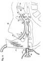
Ein verbessertes Intubationsinstrument gemäß bevorzugten Ausführungsformen der vorliegenden Erfindung ist in den
Unter besonderer Bezugnahme auf die
Der Instrumentenarm weist ein distales Ende
Wie bemerkt, wird das Instrument, mit dem distalen Ende
Genauer gesagt ist der Arm
Der Führungsweg enthält einen Abschnitt, der aus einem Kanal
Bei Näherkommen an das distale Ende des Instruments bauen sich die gegenüberliegenden vorderen Seitenkanten
Die Seitenkanten
Hier ist es nützlich zu bemerken, daß ein mit dem Instrument verwendeter Endotrachealtubus
Insbesondere ermöglicht die längliche Öffnung
Die Öse
Eine Schutzeinrichtung
Wenn sich der Arm
Das Instrument ist mit einem Klipp
Noch einmal das distale Ende
Wie früher bemerkt wurde, ist die Konfiguration der Öse
Der Tubus
Wenn zum Beispiel die in dem Ende
Die Genauigkeit, mit der das vorliegende Instrument eingeführt werden kann, ermöglicht, intermittierende Luftpulse (Überdruck) durch den Tubus
Der Freiraum
Es ist vorgesehen, daß Absaugen bei dem Freiraum
Vorzugsweise ist ein weiterer Kanal
Das durch einen oder beide Durchgänge
Man wird erkennen, daß die Anordnung der zahlreichen Komponenten des Instruments ein Instrument liefert, das im wesentlichen symmetrisch um die Längsachse des Arms und Griffes ist. Somit ist das Instrument von einem rechts- oder linkshändigen Benutzer leicht nutzbar.It will be appreciated that the arrangement of the numerous components of the instrument provides an instrument which is substantially symmetrical about the longitudinal axis of the arm and handle. Thus, the instrument is easily usable by a right-handed or left-handed user.
Es ist auch vorgesehen, daß der Kanal
Unter besonderer Bezugnahme auf
Vorzugsweise ist der Hebeabschnitt
Ein Betrachtungsapparat, der vorzugsweise eine an dem Instrument betriebsfähig gesicherte Kamera
Eine oder mehrere Leuchten, die vorzugsweise Leuchtdioden
Die Kamera
Die Anzeigeeinrichtung
Vorzugsweise ist die Kamera
Eine eng sitzende, transparente Schutzhülle (nicht gezeigt) kann über der Anordnung positioniert sein, um Reinigen zu erleichtern und für sterile Mehrfachverwendung der Einrichtung zu sorgen. Die Hülle ist eng über die Linse der Kamera eingepaßt, um zu verhindern, daß sie die Sicht behindert. Vorzugsweise ist die Hülle ein transparentes Polymer, wie zum Beispiel Kunststoff, der Schleim und Blut los wird, geringe Neigung zum Beschlagen während des Gebrauchs aufweist und Atemwegtemperatur schnell ins Gleichgewicht bringt.A tight fitting, transparent protective sheath (not shown) may be positioned over the assembly to facilitate cleaning and to provide for sterile reuse of the device. The sleeve is tightly fitted over the lens of the camera to prevent it obstructing the view. Preferably, the sheath is a transparent polymer, such as plastic, that gets rid of mucus and blood, has little tendency to fog during use, and quickly equilibrates respiratory temperature.
Das Instrument kann auch Wege (nicht gezeigt) zum Fördern von Sauerstoff und/oder Fluid zur Kameralinse enthalten, wodurch Freimachen und Reinigen der Linse während” des Betriebs unterstützt wird.The instrument may also include paths (not shown) for conveying oxygen and / or fluid to the camera lens, thereby assisting in clearing and cleaning the lens during operation.
Die Ausführungsform kann auch den Führungsweg, die Nut und die Öse zur gleitenden Aufnahme eines Endotrachealtubus
Man wird erkennen, daß die Anordnung der zahlreichen Komponenten des Instruments ein instrument liefert, das im wesentlichen symmetrisch um die Längsachse des Arms und Griffes ist. Somit ist das Instrument leicht von einem rechtshändigen oder linkshändigen Benutzer verwendbar.It will be appreciated that the arrangement of the numerous components of the instrument provides an instrument which is substantially symmetrical about the longitudinal axis of the arm and handle. Thus, the instrument is easily usable by a right-handed or left-handed user.
Unter besonderer Bezugnahme auf die
Genauer gesagt erstreckt sich ein Betätigungshebel
Die vorliegende Ausführungsform kann auch den Führungsweg, die Nut und die Öse zur gleitenden Aufnahme eines Endotrachealtubus
Während die vorliegende Erfindung bezüglich bevorzugter Ausführungsformen beschrieben worden ist, wird ein Fachmann auf dem Gebiet erkennen, daß der Schutzbereich der Erfindung nicht auf diese Ausführungsformen beschränkt ist, sondern sich auf zahlreiche Modifikationen und Äquivalente erstreckt, wie sie in den beigefügten Ansprüchen definiert sind. Zum Beispiel könnten andere Arten von Betrachtungsapparaten verwendet werden. Außerdem könnten zusätzliche Kanäle zum Liefern von weiteren Einrichtungen zum distalen Ende des Instruments vorgesehen sein.
Claims (17)
Translated fromGermanApplications Claiming Priority (6)
| Application Number | Priority Date | Filing Date | Title |
|---|---|---|---|
| US732129 | 1976-10-13 | ||
| US22333000P | 2000-08-07 | 2000-08-07 | |
| US223330P | 2000-08-07 | ||
| US09/732,129US6543447B2 (en) | 1997-12-01 | 2000-12-06 | Intubation instrument |
| PCT/CA2001/001135WO2002011608A2 (en) | 2000-08-07 | 2001-08-07 | Intubation instrument |
| EP01962510AEP1307131B2 (en) | 2000-08-07 | 2001-08-07 | Intubation instrument |
Publications (3)
| Publication Number | Publication Date |
|---|---|
| DE60111057D1 DE60111057D1 (en) | 2005-06-30 |
| DE60111057T2 DE60111057T2 (en) | 2006-05-04 |
| DE60111057T3true DE60111057T3 (en) | 2012-01-19 |
Family
ID=26917668
Family Applications (1)
| Application Number | Title | Priority Date | Filing Date |
|---|---|---|---|
| DE60111057TExpired - LifetimeDE60111057T3 (en) | 2000-08-07 | 2001-08-07 | intubation |
Country Status (10)
| Country | Link |
|---|---|
| US (2) | US6543447B2 (en) |
| EP (1) | EP1307131B2 (en) |
| JP (2) | JP2004504919A (en) |
| KR (1) | KR100801765B1 (en) |
| CN (1) | CN1217621C (en) |
| AT (1) | ATE296050T1 (en) |
| AU (1) | AU2001283738A1 (en) |
| DE (1) | DE60111057T3 (en) |
| DK (1) | DK1307131T4 (en) |
| WO (1) | WO2002011608A2 (en) |
Families Citing this family (107)
| Publication number | Priority date | Publication date | Assignee | Title |
|---|---|---|---|---|
| US6655377B2 (en)* | 1997-12-01 | 2003-12-02 | Saturn Biomedical Systems Inc. | Intubation instrument |
| US20060004260A1 (en) | 1999-10-14 | 2006-01-05 | Ben Boedeker | Endotracheal video device |
| WO2003077738A1 (en)* | 2002-03-11 | 2003-09-25 | Graumann Martin P | Digital laryngoscope |
| US7182728B2 (en)* | 2002-07-24 | 2007-02-27 | Intubation Plus, Inc. | Laryngoscope with multi-directional eyepiece |
| JP5044741B2 (en)* | 2002-10-03 | 2012-10-10 | イーティービュー リミテッド | Multi-functional tracheal tube and system including the tube |
| EP2505125A1 (en) | 2003-04-29 | 2012-10-03 | Aircraft Medical Limited | Laryngoscope with camera attachment |
| US20050067103A1 (en)* | 2003-09-26 | 2005-03-31 | Applied Materials, Inc. | Interferometer endpoint monitoring device |
| JP2005143756A (en)* | 2003-11-13 | 2005-06-09 | Scalar Corp | Oral airway and airway maintenance aid |
| DE102004028428A1 (en)* | 2004-06-03 | 2006-01-26 | Karl Storz Gmbh & Co. Kg | laryngoscope |
| DE102004035269A1 (en)* | 2004-07-21 | 2006-02-16 | Rowiak Gmbh | Laryngoscope with OCT |
| AU2005278773A1 (en)* | 2004-09-03 | 2006-03-09 | Stryker Gi Ltd. | Optical head for endoscope |
| US8827899B2 (en)* | 2004-09-24 | 2014-09-09 | Vivid Medical, Inc. | Disposable endoscopic access device and portable display |
| US9033870B2 (en) | 2004-09-24 | 2015-05-19 | Vivid Medical, Inc. | Pluggable vision module and portable display for endoscopy |
| JP4814504B2 (en)* | 2004-09-27 | 2011-11-16 | 淳一 小山 | Intubation support tool and intubation support device |
| JP2006087840A (en)* | 2004-09-27 | 2006-04-06 | Junichi Koyama | Intubation support device |
| US20070068530A1 (en)* | 2004-11-19 | 2007-03-29 | Pacey John A | Secretion clearing ventilation catheter and airway management system |
| EP1868486A4 (en)* | 2005-04-01 | 2012-11-14 | Verathon Medical Canada Ulc | Video retractor |
| US7464539B2 (en)* | 2005-04-29 | 2008-12-16 | Emcon Technologies Llc | Method and apparatus for supplying air to emission abatement device by use of turbocharger |
| US7921847B2 (en) | 2005-07-25 | 2011-04-12 | Intubix, Llc | Device and method for placing within a patient an enteral tube after endotracheal intubation |
| US8863746B2 (en)* | 2005-07-25 | 2014-10-21 | Kim Technology Partners, LP | Device and method for placing within a patient an enteral tube after endotracheal intubation |
| JP4964452B2 (en)* | 2005-10-24 | 2012-06-27 | Hoya株式会社 | Intubation support device |
| JP4761928B2 (en) | 2005-10-24 | 2011-08-31 | Hoya株式会社 | Intubation support device |
| EP1968426B1 (en)* | 2005-12-19 | 2013-09-25 | Techmin Pty Ltd | Induction coil sensing |
| GB2447601A (en)* | 2006-01-06 | 2008-09-17 | Lavern Roxanne Bentt | Oxygenating laryngoscope |
| US20070197873A1 (en)* | 2006-02-21 | 2007-08-23 | Karl Storz Gmbh & Co. Kg | Wireless optical endoscopic device |
| US7976459B2 (en)* | 2006-10-17 | 2011-07-12 | Intra L.L.C. | Portable endoscope for intubation |
| US20080216840A1 (en)* | 2007-03-06 | 2008-09-11 | Searete Llc, A Limited Liability Corporation Of The State Of Delaware | Imaging via the airway |
| US8029440B2 (en)* | 2007-04-04 | 2011-10-04 | Karl Storz Endovision, Inc. | Video blade laryngoscope |
| US9386914B2 (en)* | 2007-04-04 | 2016-07-12 | Karl Storz Endovision, Inc. | Video endoscopic device with detachable control circuit |
| US8419634B2 (en) | 2007-06-12 | 2013-04-16 | University Hospitals Of Cleveland | Apparatus and method for airway management |
| AU2008266236B2 (en)* | 2007-06-12 | 2012-04-12 | Avn Medical Technologies, Llc | Airway management |
| US8460184B2 (en)* | 2009-12-11 | 2013-06-11 | University Hospitals Of Cleveland | Airway management |
| CA2625548C (en) | 2007-08-04 | 2012-04-10 | John A. Law | An airway intubation device |
| US20080216826A1 (en)* | 2007-08-07 | 2008-09-11 | Searete Llc, A Limited Liability Corporation Of The State Of Delaware | Airway imaging system |
| US20090024018A1 (en)* | 2007-08-07 | 2009-01-22 | Searete Llc, A Limited Liability Corporation Of The State Of Delaware | Anatomical imaging system |
| EP3199094B1 (en) | 2007-08-28 | 2020-10-21 | Aircraft Medical Limited | Laryngoscope insertion section |
| GB0716672D0 (en)* | 2007-08-28 | 2007-10-03 | Aircraft Medical Ltd | Laryngoscope |
| GB0819942D0 (en)* | 2008-10-30 | 2008-12-10 | Indian Ocean Medical Inc | Guiding device for use with laryngoscope |
| US8998804B2 (en)* | 2008-11-12 | 2015-04-07 | Board Of Regents Of The University Of Nebraska | Suction catheter assembly for a laryngoscope |
| US20100198017A1 (en)* | 2009-01-30 | 2010-08-05 | Taps, Llc | Laryngoscope Blade |
| WO2010091309A1 (en) | 2009-02-06 | 2010-08-12 | Endoclear, Llc | Methods for cleaning endotracheal tubes |
| US8468637B2 (en) | 2009-02-06 | 2013-06-25 | Endoclear Llc | Mechanically-actuated endotracheal tube cleaning device |
| GB0903612D0 (en)* | 2009-03-03 | 2009-04-08 | Aircraft Medical Ltd | Laryngoscope insertion section with tube guide |
| HRP20211849T1 (en) | 2009-03-31 | 2022-03-04 | Dilon Technologies, Inc. | Laryngoscope and system |
| US8394016B1 (en) | 2009-07-02 | 2013-03-12 | Bruce Cabot Arné | Illuminated airway article |
| DE102009028083A1 (en)* | 2009-07-29 | 2011-02-10 | Schönhage, Kai, Dr., Tucson | intubation |
| US9119926B2 (en) | 2009-07-31 | 2015-09-01 | Avent, Inc. | Subglottic suctioning system |
| USD637717S1 (en) | 2009-10-02 | 2011-05-10 | Indian Ocean Medical Inc. | Laryngoscope |
| CA2781059A1 (en)* | 2009-11-16 | 2011-05-19 | Verathon Inc. | Channel laryngoscopes and systems |
| US9179831B2 (en)* | 2009-11-30 | 2015-11-10 | King Systems Corporation | Visualization instrument |
| US9445714B2 (en) | 2010-03-29 | 2016-09-20 | Endoclear Llc | Endotracheal tube coupling adapters |
| EP2552293B1 (en) | 2010-03-29 | 2015-01-07 | Endoclear LLC | Airway cleaning and visualization |
| US20130072913A1 (en)* | 2010-05-17 | 2013-03-21 | Industry-University Cooperation Foundation Hanyang University Erica Campus | Medical device for surgery |
| JP2011255095A (en)* | 2010-06-11 | 2011-12-22 | Olympus Medical Systems Corp | Medical assistance device and medical system |
| US8414481B2 (en) | 2010-06-24 | 2013-04-09 | General Electric Company | Laryngoscope |
| US9289114B2 (en)* | 2010-07-30 | 2016-03-22 | Nilesh R. Vasan | Disposable, self-contained laryngoscope and method of using same |
| MX350734B (en) | 2010-09-08 | 2017-09-15 | Covidien Lp | Catheter with imaging assembly. |
| DK201001052A (en) | 2010-11-19 | 2011-11-10 | Ambu As | A tracheal intubation guide |
| EP2535075A1 (en) | 2011-06-15 | 2012-12-19 | Medizinische Hochschule Hannover | Medical device for conducting a laryngoscopy and/or an intubation |
| AU2012282150B2 (en) | 2011-07-11 | 2017-01-19 | Ambu A/S | Endobronchial tube |
| US20130014750A1 (en)* | 2011-07-14 | 2013-01-17 | Soheil Etesham | Intubation Apparatus |
| TWM429482U (en)* | 2011-09-09 | 2012-05-21 | Tien-Sheng Chen | Tracheal intubation device |
| GB201119797D0 (en)* | 2011-11-16 | 2011-12-28 | Aircraft Medical Ltd | Laryngoscope and kit comprising laryngoscope and blades |
| USD695401S1 (en) | 2011-12-23 | 2013-12-10 | Karl Storz Gmbh & Co. Kg | Laryngoscope |
| US20130197313A1 (en)* | 2012-01-31 | 2013-08-01 | Shaw P. Wan | Surgical retractor with light |
| US9415179B2 (en) | 2012-06-01 | 2016-08-16 | Wm & Dg, Inc. | Medical device, and the methods of using same |
| US9357905B2 (en) | 2012-06-01 | 2016-06-07 | Robert Molnar | Airway device, airway assist device and the method of using same |
| AU2013290002A1 (en)* | 2012-07-13 | 2015-01-29 | The Henry M. Jackson Foundation For The Advancement Of Military Medicine, Inc | Infrared illuminated airway management devices and kits and methods for using the same |
| US9198835B2 (en) | 2012-09-07 | 2015-12-01 | Covidien Lp | Catheter with imaging assembly with placement aid and related methods therefor |
| US9517184B2 (en) | 2012-09-07 | 2016-12-13 | Covidien Lp | Feeding tube with insufflation device and related methods therefor |
| USD735343S1 (en) | 2012-09-07 | 2015-07-28 | Covidien Lp | Console |
| USD716841S1 (en) | 2012-09-07 | 2014-11-04 | Covidien Lp | Display screen with annotate file icon |
| USD717340S1 (en) | 2012-09-07 | 2014-11-11 | Covidien Lp | Display screen with enteral feeding icon |
| US9107628B2 (en) | 2012-10-12 | 2015-08-18 | Karl Storz Gmbh & Co. Kg | Video laryngoscope with disposable blade |
| US10165937B2 (en) | 2012-11-13 | 2019-01-01 | Karl Storz Imaging, Inc. | Configurable anesthesia safety system |
| US10165938B2 (en) | 2012-11-13 | 2019-01-01 | Karl Storz Imaging, Inc. | Configurable medical video safety system |
| US10004863B2 (en) | 2012-12-04 | 2018-06-26 | Endoclear Llc | Closed suction cleaning devices, systems and methods |
| EP2754384B1 (en) | 2013-01-10 | 2018-07-11 | Ambu A/S | Endobronchial tube with integrated image sensor and cleaning nozzle arrangement |
| GB201308528D0 (en) | 2013-05-11 | 2013-06-19 | Smiths Medical Int Ltd | Medico-surgical viewing assemblies guides and introducers |
| WO2014200674A2 (en) | 2013-05-20 | 2014-12-18 | Nacouzi Vincent | Laryngoscope |
| US9295798B2 (en) | 2013-10-09 | 2016-03-29 | Danny Martin Sartore | Laryngoscopic device with drug and oxygen delivery conduits |
| USD742512S1 (en)* | 2013-10-16 | 2015-11-03 | Karl Storz Gmbh & Co. Kg | Spreadable laryngoscope |
| CA2930662A1 (en) | 2013-11-15 | 2015-05-21 | Ciel Medical, Inc. | Devices and methods for airway suctioning |
| CN106132281A (en)* | 2014-01-31 | 2016-11-16 | 路易斯威尔大学研究基金会有限公司 | There is integration and can the laryngoscope of control and suck |
| US9427543B2 (en)* | 2014-05-05 | 2016-08-30 | Deye Wei | Intubation device and method |
| WO2015187583A1 (en) | 2014-06-03 | 2015-12-10 | Endoclear Llc | Cleaning devices, systems and methods |
| US10722110B2 (en) | 2014-08-08 | 2020-07-28 | Wm & Dg, Inc. | Medical devices and methods of placement |
| US11147442B2 (en) | 2014-08-08 | 2021-10-19 | Wm & Dg, Inc. | Medical devices and methods of placement |
| US9918618B2 (en)* | 2014-08-08 | 2018-03-20 | Wm & Dg, Inc. | Medical devices and methods of placement |
| US11633093B2 (en) | 2014-08-08 | 2023-04-25 | Wm & Dg, Inc. | Medical devices and methods of placement |
| CN104224092B (en)* | 2014-09-19 | 2016-08-17 | 珠海普生医疗科技有限公司 | Elder generation of endoscope end construction |
| US10265046B2 (en) | 2014-11-26 | 2019-04-23 | Visura Technologies, Inc. | Apparatus, system and methods for proper transesophageal echocardiography probe positioning by using camera for ultrasound imaging |
| US10045758B2 (en)* | 2014-11-26 | 2018-08-14 | Visura Technologies, LLC | Apparatus, systems and methods for proper transesophageal echocardiography probe positioning by using camera for ultrasound imaging |
| JP5855776B1 (en)* | 2015-01-22 | 2016-02-09 | 永島医科器械株式会社 | Throat larynx mirror |
| US10765310B2 (en)* | 2015-08-03 | 2020-09-08 | Dina Abi Fadel | Laryngoscope with blade position adjustment |
| WO2017024007A1 (en) | 2015-08-05 | 2017-02-09 | Inscope Medical Solutions, Inc. | Medical device with an airway insertion member |
| US10478054B2 (en) | 2016-02-12 | 2019-11-19 | Ambu A/S | Endotracheal tube with visualization capabilities and a laryngeal mask |
| JP2019508143A (en) | 2016-03-01 | 2019-03-28 | インスコープ メディカル ソリューションズ インコーポレイテッド | Improved laryngoscope |
| US11051682B2 (en) | 2017-08-31 | 2021-07-06 | Wm & Dg, Inc. | Medical devices with camera and methods of placement |
| USD876625S1 (en) | 2018-08-07 | 2020-02-25 | Adroit Surgical, Llc | Laryngoscope |
| US10653307B2 (en) | 2018-10-10 | 2020-05-19 | Wm & Dg, Inc. | Medical devices for airway management and methods of placement |
| US12257387B2 (en) | 2018-10-10 | 2025-03-25 | Wm & Dg, Inc. | Medical devices for airway management and methods of placement |
| USD921185S1 (en)* | 2019-01-24 | 2021-06-01 | Sridhar R. Musuku | Intubation device |
| US12167947B2 (en)* | 2019-06-14 | 2024-12-17 | Kim L. Racine | Suction hood for dental prophy angle |
| US20210162154A1 (en)* | 2019-11-30 | 2021-06-03 | Yang Sun | A Supraglottic Airway Device for intermittent Positive Pressure Ventilation |
| US11497394B2 (en) | 2020-10-12 | 2022-11-15 | Wm & Dg, Inc. | Laryngoscope and intubation methods |
| US20250072741A1 (en)* | 2023-08-28 | 2025-03-06 | Brandon Walker | Video laryngoscopic tracheoscope |
Family Cites Families (44)
| Publication number | Priority date | Publication date | Assignee | Title |
|---|---|---|---|---|
| US3771514A (en) | 1971-06-29 | 1973-11-13 | Concept | Laryngoscope |
| US4114609A (en) | 1975-07-16 | 1978-09-19 | Moses John A | Laryngoscope |
| US4126127A (en)* | 1976-09-27 | 1978-11-21 | May Laurence M | Suctioning/oxygenating laryngoscope blade |
| FR2453606A1 (en)* | 1978-07-04 | 1980-11-07 | Salomon & Fils F | PIVOT SKI FIXING ASSEMBLY HAVING A BRAKING SYSTEM |
| US4306547A (en)* | 1979-11-20 | 1981-12-22 | Lowell James R | Rigid fiberoptic laryngoscope |
| US4337761A (en) | 1979-11-28 | 1982-07-06 | Upsher Michael S | Laryngoscope |
| US4360008A (en) | 1980-09-02 | 1982-11-23 | Corazzelli Jr Frank G | Laryngoscope |
| NZ198715A (en)† | 1980-11-11 | 1984-08-24 | Avulunga Pty Ltd | Laryngoscope |
| FR2551491B1 (en) | 1983-08-31 | 1986-02-28 | Elf Aquitaine | MULTIDRAIN OIL DRILLING AND PRODUCTION DEVICE |
| US4573451A (en) | 1984-11-08 | 1986-03-04 | Jack Bauman | Laryngoscope blade with a bendable tip |
| US5016614A (en)* | 1985-11-07 | 1991-05-21 | Macallister Niall P | Endotracheal intubation apparatus |
| US4793327A (en)* | 1986-01-21 | 1988-12-27 | Frankel Alfred R | Device for opening a patient's airway during automatic intubation of the trachea |
| GB2189148B (en) | 1986-04-16 | 1990-04-18 | Wolf Gmbh Richard | Laryngoscope |
| US5042469A (en)* | 1987-03-24 | 1991-08-27 | Augustine Medical, Inc. | Tracheal intubation guide |
| US5203320A (en)* | 1987-03-24 | 1993-04-20 | Augustine Medical, Inc. | Tracheal intubation guide |
| US4846153A (en) | 1988-06-10 | 1989-07-11 | George Berci | Intubating video endoscope |
| US4877016A (en)† | 1988-07-29 | 1989-10-31 | Kantor Edward A | Video endoscopic microscope |
| US4947896A (en)* | 1988-11-04 | 1990-08-14 | Bartlett Robert L | Laryngoscope |
| US4982729A (en) | 1989-02-10 | 1991-01-08 | Wu Tzu Lang | Rigid fiberoptic intubating laryngoscope |
| US5003962A (en) | 1989-05-10 | 1991-04-02 | Choi Jay J | Laryngoscope with double-angle blade |
| US5443058A (en) | 1989-05-26 | 1995-08-22 | Ough; Yon D. | Blade for telescopic laryngoscope |
| US5174283A (en) | 1989-11-08 | 1992-12-29 | Parker Jeffrey D | Blind orolaryngeal and oroesophageal guiding and aiming device |
| US5038766A (en) | 1989-11-08 | 1991-08-13 | Parker Jeffrey D | Blind orolaryngeal and oroesophageal guiding and aiming device |
| WO1991012044A1 (en) | 1990-02-14 | 1991-08-22 | Adair Edwin Lloyd | Endotracheal tube intubation assist device |
| US5381787A (en) | 1990-05-04 | 1995-01-17 | Bullard; James R. | Extendable and retractable laryngoscope |
| US5095888A (en) | 1990-07-09 | 1992-03-17 | Circon Corporation | Intubating stylet for a laryngoscope |
| US5183031A (en) | 1991-05-13 | 1993-02-02 | Rossoff Leonard J | Fiberoptic intubating laryngoscope |
| US5261392A (en) | 1992-04-03 | 1993-11-16 | Achi Corporation | Laryngoscope with interchangeable fiberoptic assembly |
| US5431152A (en) | 1993-09-21 | 1995-07-11 | Flam; Gary H. | Oral fiberoptic intubating apparatus and method |
| US5498231A (en)* | 1994-03-07 | 1996-03-12 | Franicevic; Klaus | Intubating laryngoscope |
| US5645519A (en) | 1994-03-18 | 1997-07-08 | Jai S. Lee | Endoscopic instrument for controlled introduction of tubular members in the body and methods therefor |
| US5551946A (en) | 1994-05-17 | 1996-09-03 | Bullard; James R. | Multifunctional intubating guide stylet and laryngoscope |
| US5513627A (en) | 1995-01-27 | 1996-05-07 | Flam; Gary H. | Esophageal tracheal intubator airway |
| US5603688A (en) | 1995-04-24 | 1997-02-18 | Upsher Laryngoscope Corporation | Laryngoscope including an upwardly curved blade having a downwardly directed tip portion |
| US5676635A (en) | 1995-08-30 | 1997-10-14 | Levin; Bruce | Instrument for insertion of an endotracheal tube |
| US5800344A (en) | 1996-10-23 | 1998-09-01 | Welch Allyn, Inc. | Video laryngoscope |
| JPH10127579A (en)* | 1996-11-02 | 1998-05-19 | Takeshi Okada | Laryngoscope |
| GR1002809B (en)† | 1996-11-07 | 1997-11-13 | Laryngoscope consisting of a handle, a curved blade and a light bulb, has a joint placed in the proximal to the handle one-third of its blade and a balloon placed on the distal to the handle one third of the concave surface of its blade. | |
| US5827178A (en) | 1997-01-02 | 1998-10-27 | Berall; Jonathan | Laryngoscope for use in trachea intubation |
| US5845634A (en) | 1997-03-18 | 1998-12-08 | Parker Medical Limited Partnership | Endoscope viewing system with orotracheal introducing guide |
| US6142144A (en) | 1997-12-01 | 2000-11-07 | Pacey; John A. | Intubation instrument |
| WO1999044490A1 (en)† | 1998-03-01 | 1999-09-10 | Volpi Ag | Laryngoscope |
| JP2000175867A (en)* | 1998-12-15 | 2000-06-27 | Moritex Corp | Laryngoscope |
| US6135948A (en)* | 1999-01-25 | 2000-10-24 | Lee; Han Shik | Convertible laryngoscope |
- 2000
- 2000-12-06USUS09/732,129patent/US6543447B2/ennot_activeExpired - Fee Related
- 2001
- 2001-08-07CNCN018138632Apatent/CN1217621C/ennot_activeExpired - Fee Related
- 2001-08-07DKDK01962510.2Tpatent/DK1307131T4/enactive
- 2001-08-07JPJP2002516952Apatent/JP2004504919A/enactivePending
- 2001-08-07ATAT01962510Tpatent/ATE296050T1/ennot_activeIP Right Cessation
- 2001-08-07KRKR1020037001588Apatent/KR100801765B1/ennot_activeExpired - Fee Related
- 2001-08-07EPEP01962510Apatent/EP1307131B2/ennot_activeExpired - Lifetime
- 2001-08-07DEDE60111057Tpatent/DE60111057T3/ennot_activeExpired - Lifetime
- 2001-08-07WOPCT/CA2001/001135patent/WO2002011608A2/enactiveIP Right Grant
- 2001-08-07AUAU2001283738Apatent/AU2001283738A1/ennot_activeAbandoned
- 2007
- 2007-10-27USUS11/925,868patent/US20080146879A1/ennot_activeAbandoned
- 2012
- 2012-03-15JPJP2012058737Apatent/JP2012161617A/enactivePending
Also Published As
| Publication number | Publication date |
|---|---|
| WO2002011608A3 (en) | 2002-04-04 |
| DK1307131T4 (en) | 2011-02-21 |
| WO2002011608A2 (en) | 2002-02-14 |
| KR100801765B1 (en) | 2008-02-05 |
| CN1217621C (en) | 2005-09-07 |
| AU2001283738A1 (en) | 2002-02-18 |
| EP1307131A2 (en) | 2003-05-07 |
| JP2012161617A (en) | 2012-08-30 |
| ATE296050T1 (en) | 2005-06-15 |
| KR20030019647A (en) | 2003-03-06 |
| DE60111057T2 (en) | 2006-05-04 |
| CN1452472A (en) | 2003-10-29 |
| US20010023312A1 (en) | 2001-09-20 |
| US20080146879A1 (en) | 2008-06-19 |
| EP1307131B2 (en) | 2010-11-10 |
| DE60111057D1 (en) | 2005-06-30 |
| DK1307131T3 (en) | 2005-09-26 |
| HK1057323A1 (en) | 2004-04-02 |
| EP1307131B1 (en) | 2005-05-25 |
| JP2004504919A (en) | 2004-02-19 |
| US6543447B2 (en) | 2003-04-08 |
Similar Documents
| Publication | Publication Date | Title |
|---|---|---|
| DE60111057T3 (en) | intubation | |
| DE4039746C2 (en) | Rigid, fiber optic intubation laryngoscope | |
| DE69030998T2 (en) | DEVICE FOR ORALARYNAL AND ORESOPHAGEAL BLINDING AND TARGETING | |
| EP1150734B1 (en) | Device for introducing an intubation tube into the trachea | |
| US5095888A (en) | Intubating stylet for a laryngoscope | |
| EP1062905B1 (en) | Intubating laryngoscope providing for ready interchange of blades and corresponding intubating laryngoscope system | |
| DE69022979T2 (en) | RIGID VIDEO ENDOSCOPE WITH HEAT-STERILIZABLE COVER. | |
| DE69526226T2 (en) | INTUBATIONAL DEVICE WITH A FIBERGLASS FIBER OPTIC AND THROAT MASK | |
| DE69931621T2 (en) | ENDOSCOPIC INSTRUMENT WITH WORK CHANNEL | |
| DE10024728A1 (en) | Unit cleaning endoscopic instrument window in-situ during intervention, comprises detachable end casing with insufflation- and flushing channels | |
| DE19518148A1 (en) | Intubation guide and laryngoscope | |
| US7563227B2 (en) | Instrument for direct laryngoscopy with a rigid blade and flexible fiberoptics | |
| DE2728910A1 (en) | LARYNGOSCOPE | |
| DE102006050076A1 (en) | Intubationshilfsgerät | |
| GB2407990A (en) | Oral airway. | |
| DE29723780U1 (en) | Surgical instrument for emergency medicine | |
| DE3853279T2 (en) | LARYNGOSKOP. | |
| DE2950520C2 (en) | Endoscope for a tracheal catheter | |
| WO1999044490A1 (en) | Laryngoscope | |
| DE3939859A1 (en) | Dental vacuum instrument removing cooling water and organic material - is connected to light source for integrated illumination of working area | |
| EP1299027B1 (en) | Laryngoscope | |
| DE1907235A1 (en) | Endoscope for examinations in the ear, nose and throat area | |
| DE9400049U1 (en) | Intubation forceps | |
| DD261310A1 (en) | MANDRIN FOR THE INTUBATION | |
| DE8907337U1 (en) | Device for nasotracheal intubation |
Legal Events
| Date | Code | Title | Description |
|---|---|---|---|
| 8327 | Change in the person/name/address of the patent owner | Owner name:VERATHON MEDICAL (CANADA) ULC, HALIFAX, CA | |
| 8363 | Opposition against the patent | ||
| 8366 | Restricted maintained after opposition proceedings |