DE4345610B4 - Method for producing a radio-frequency identification device (HFID) - Google Patents
Method for producing a radio-frequency identification device (HFID)Download PDFInfo
- Publication number
- DE4345610B4 DE4345610B4DE4345610ADE4345610ADE4345610B4DE 4345610 B4DE4345610 B4DE 4345610B4DE 4345610 ADE4345610 ADE 4345610ADE 4345610 ADE4345610 ADE 4345610ADE 4345610 B4DE4345610 B4DE 4345610B4
- Authority
- DE
- Germany
- Prior art keywords
- battery
- chip
- carrier element
- integrated circuit
- antenna
- Prior art date
- Legal status (The legal status is an assumption and is not a legal conclusion. Google has not performed a legal analysis and makes no representation as to the accuracy of the status listed.)
- Expired - Lifetime
Links
Images


Classifications
- H—ELECTRICITY
- H01—ELECTRIC ELEMENTS
- H01Q—ANTENNAS, i.e. RADIO AERIALS
- H01Q1/00—Details of, or arrangements associated with, antennas
- H01Q1/12—Supports; Mounting means
- H01Q1/22—Supports; Mounting means by structural association with other equipment or articles
- H01Q1/2208—Supports; Mounting means by structural association with other equipment or articles associated with components used in interrogation type services, i.e. in systems for information exchange between an interrogator/reader and a tag/transponder, e.g. in Radio Frequency Identification [RFID] systems
- H01Q1/2225—Supports; Mounting means by structural association with other equipment or articles associated with components used in interrogation type services, i.e. in systems for information exchange between an interrogator/reader and a tag/transponder, e.g. in Radio Frequency Identification [RFID] systems used in active tags, i.e. provided with its own power source or in passive tags, i.e. deriving power from RF signal
- G—PHYSICS
- G01—MEASURING; TESTING
- G01S—RADIO DIRECTION-FINDING; RADIO NAVIGATION; DETERMINING DISTANCE OR VELOCITY BY USE OF RADIO WAVES; LOCATING OR PRESENCE-DETECTING BY USE OF THE REFLECTION OR RERADIATION OF RADIO WAVES; ANALOGOUS ARRANGEMENTS USING OTHER WAVES
- G01S13/00—Systems using the reflection or reradiation of radio waves, e.g. radar systems; Analogous systems using reflection or reradiation of waves whose nature or wavelength is irrelevant or unspecified
- G01S13/74—Systems using reradiation of radio waves, e.g. secondary radar systems; Analogous systems
- G01S13/75—Systems using reradiation of radio waves, e.g. secondary radar systems; Analogous systems using transponders powered from received waves, e.g. using passive transponders, or using passive reflectors
- G01S13/751—Systems using reradiation of radio waves, e.g. secondary radar systems; Analogous systems using transponders powered from received waves, e.g. using passive transponders, or using passive reflectors wherein the responder or reflector radiates a coded signal
- G01S13/758—Systems using reradiation of radio waves, e.g. secondary radar systems; Analogous systems using transponders powered from received waves, e.g. using passive transponders, or using passive reflectors wherein the responder or reflector radiates a coded signal using a signal generator powered by the interrogation signal
- G—PHYSICS
- G01—MEASURING; TESTING
- G01S—RADIO DIRECTION-FINDING; RADIO NAVIGATION; DETERMINING DISTANCE OR VELOCITY BY USE OF RADIO WAVES; LOCATING OR PRESENCE-DETECTING BY USE OF THE REFLECTION OR RERADIATION OF RADIO WAVES; ANALOGOUS ARRANGEMENTS USING OTHER WAVES
- G01S13/00—Systems using the reflection or reradiation of radio waves, e.g. radar systems; Analogous systems using reflection or reradiation of waves whose nature or wavelength is irrelevant or unspecified
- G01S13/74—Systems using reradiation of radio waves, e.g. secondary radar systems; Analogous systems
- G01S13/76—Systems using reradiation of radio waves, e.g. secondary radar systems; Analogous systems wherein pulse-type signals are transmitted
- G01S13/767—Responders; Transponders
- G—PHYSICS
- G06—COMPUTING OR CALCULATING; COUNTING
- G06K—GRAPHICAL DATA READING; PRESENTATION OF DATA; RECORD CARRIERS; HANDLING RECORD CARRIERS
- G06K19/00—Record carriers for use with machines and with at least a part designed to carry digital markings
- G06K19/06—Record carriers for use with machines and with at least a part designed to carry digital markings characterised by the kind of the digital marking, e.g. shape, nature, code
- G06K19/067—Record carriers with conductive marks, printed circuits or semiconductor circuit elements, e.g. credit or identity cards also with resonating or responding marks without active components
- G06K19/07—Record carriers with conductive marks, printed circuits or semiconductor circuit elements, e.g. credit or identity cards also with resonating or responding marks without active components with integrated circuit chips
- G06K19/0701—Record carriers with conductive marks, printed circuits or semiconductor circuit elements, e.g. credit or identity cards also with resonating or responding marks without active components with integrated circuit chips at least one of the integrated circuit chips comprising an arrangement for power management
- G06K19/0702—Record carriers with conductive marks, printed circuits or semiconductor circuit elements, e.g. credit or identity cards also with resonating or responding marks without active components with integrated circuit chips at least one of the integrated circuit chips comprising an arrangement for power management the arrangement including a battery
- G—PHYSICS
- G06—COMPUTING OR CALCULATING; COUNTING
- G06K—GRAPHICAL DATA READING; PRESENTATION OF DATA; RECORD CARRIERS; HANDLING RECORD CARRIERS
- G06K19/00—Record carriers for use with machines and with at least a part designed to carry digital markings
- G06K19/06—Record carriers for use with machines and with at least a part designed to carry digital markings characterised by the kind of the digital marking, e.g. shape, nature, code
- G06K19/067—Record carriers with conductive marks, printed circuits or semiconductor circuit elements, e.g. credit or identity cards also with resonating or responding marks without active components
- G06K19/07—Record carriers with conductive marks, printed circuits or semiconductor circuit elements, e.g. credit or identity cards also with resonating or responding marks without active components with integrated circuit chips
- G06K19/0723—Record carriers with conductive marks, printed circuits or semiconductor circuit elements, e.g. credit or identity cards also with resonating or responding marks without active components with integrated circuit chips the record carrier comprising an arrangement for non-contact communication, e.g. wireless communication circuits on transponder cards, non-contact smart cards or RFIDs
- G—PHYSICS
- G06—COMPUTING OR CALCULATING; COUNTING
- G06K—GRAPHICAL DATA READING; PRESENTATION OF DATA; RECORD CARRIERS; HANDLING RECORD CARRIERS
- G06K19/00—Record carriers for use with machines and with at least a part designed to carry digital markings
- G06K19/06—Record carriers for use with machines and with at least a part designed to carry digital markings characterised by the kind of the digital marking, e.g. shape, nature, code
- G06K19/067—Record carriers with conductive marks, printed circuits or semiconductor circuit elements, e.g. credit or identity cards also with resonating or responding marks without active components
- G06K19/07—Record carriers with conductive marks, printed circuits or semiconductor circuit elements, e.g. credit or identity cards also with resonating or responding marks without active components with integrated circuit chips
- G06K19/073—Special arrangements for circuits, e.g. for protecting identification code in memory
- G—PHYSICS
- G06—COMPUTING OR CALCULATING; COUNTING
- G06K—GRAPHICAL DATA READING; PRESENTATION OF DATA; RECORD CARRIERS; HANDLING RECORD CARRIERS
- G06K19/00—Record carriers for use with machines and with at least a part designed to carry digital markings
- G06K19/06—Record carriers for use with machines and with at least a part designed to carry digital markings characterised by the kind of the digital marking, e.g. shape, nature, code
- G06K19/067—Record carriers with conductive marks, printed circuits or semiconductor circuit elements, e.g. credit or identity cards also with resonating or responding marks without active components
- G06K19/07—Record carriers with conductive marks, printed circuits or semiconductor circuit elements, e.g. credit or identity cards also with resonating or responding marks without active components with integrated circuit chips
- G06K19/077—Constructional details, e.g. mounting of circuits in the carrier
- G06K19/07749—Constructional details, e.g. mounting of circuits in the carrier the record carrier being capable of non-contact communication, e.g. constructional details of the antenna of a non-contact smart card
- G06K19/07773—Antenna details
- G06K19/07786—Antenna details the antenna being of the HF type, such as a dipole
- G—PHYSICS
- G06—COMPUTING OR CALCULATING; COUNTING
- G06K—GRAPHICAL DATA READING; PRESENTATION OF DATA; RECORD CARRIERS; HANDLING RECORD CARRIERS
- G06K7/00—Methods or arrangements for sensing record carriers, e.g. for reading patterns
- G06K7/10—Methods or arrangements for sensing record carriers, e.g. for reading patterns by electromagnetic radiation, e.g. optical sensing; by corpuscular radiation
- G06K7/10009—Methods or arrangements for sensing record carriers, e.g. for reading patterns by electromagnetic radiation, e.g. optical sensing; by corpuscular radiation sensing by radiation using wavelengths larger than 0.1 mm, e.g. radio-waves or microwaves
- G06K7/10316—Methods or arrangements for sensing record carriers, e.g. for reading patterns by electromagnetic radiation, e.g. optical sensing; by corpuscular radiation sensing by radiation using wavelengths larger than 0.1 mm, e.g. radio-waves or microwaves using at least one antenna particularly designed for interrogating the wireless record carriers
- G06K7/10346—Methods or arrangements for sensing record carriers, e.g. for reading patterns by electromagnetic radiation, e.g. optical sensing; by corpuscular radiation sensing by radiation using wavelengths larger than 0.1 mm, e.g. radio-waves or microwaves using at least one antenna particularly designed for interrogating the wireless record carriers the antenna being of the far field type, e.g. HF types or dipoles
- H—ELECTRICITY
- H01—ELECTRIC ELEMENTS
- H01L—SEMICONDUCTOR DEVICES NOT COVERED BY CLASS H10
- H01L23/00—Details of semiconductor or other solid state devices
- H01L23/48—Arrangements for conducting electric current to or from the solid state body in operation, e.g. leads, terminal arrangements ; Selection of materials therefor
- H01L23/488—Arrangements for conducting electric current to or from the solid state body in operation, e.g. leads, terminal arrangements ; Selection of materials therefor consisting of soldered or bonded constructions
- H01L23/498—Leads, i.e. metallisations or lead-frames on insulating substrates, e.g. chip carriers
- H01L23/49855—Leads, i.e. metallisations or lead-frames on insulating substrates, e.g. chip carriers for flat-cards, e.g. credit cards
- H—ELECTRICITY
- H01—ELECTRIC ELEMENTS
- H01L—SEMICONDUCTOR DEVICES NOT COVERED BY CLASS H10
- H01L23/00—Details of semiconductor or other solid state devices
- H01L23/52—Arrangements for conducting electric current within the device in operation from one component to another, i.e. interconnections, e.g. wires, lead frames
- H01L23/538—Arrangements for conducting electric current within the device in operation from one component to another, i.e. interconnections, e.g. wires, lead frames the interconnection structure between a plurality of semiconductor chips being formed on, or in, insulating substrates
- H01L23/5389—Arrangements for conducting electric current within the device in operation from one component to another, i.e. interconnections, e.g. wires, lead frames the interconnection structure between a plurality of semiconductor chips being formed on, or in, insulating substrates the chips being integrally enclosed by the interconnect and support structures
- H—ELECTRICITY
- H01—ELECTRIC ELEMENTS
- H01L—SEMICONDUCTOR DEVICES NOT COVERED BY CLASS H10
- H01L24/00—Arrangements for connecting or disconnecting semiconductor or solid-state bodies; Methods or apparatus related thereto
- H01L24/01—Means for bonding being attached to, or being formed on, the surface to be connected, e.g. chip-to-package, die-attach, "first-level" interconnects; Manufacturing methods related thereto
- H01L24/18—High density interconnect [HDI] connectors; Manufacturing methods related thereto
- H01L24/23—Structure, shape, material or disposition of the high density interconnect connectors after the connecting process
- H01L24/24—Structure, shape, material or disposition of the high density interconnect connectors after the connecting process of an individual high density interconnect connector
- H—ELECTRICITY
- H01—ELECTRIC ELEMENTS
- H01L—SEMICONDUCTOR DEVICES NOT COVERED BY CLASS H10
- H01L24/00—Arrangements for connecting or disconnecting semiconductor or solid-state bodies; Methods or apparatus related thereto
- H01L24/80—Methods for connecting semiconductor or other solid state bodies using means for bonding being attached to, or being formed on, the surface to be connected
- H01L24/82—Methods for connecting semiconductor or other solid state bodies using means for bonding being attached to, or being formed on, the surface to be connected by forming build-up interconnects at chip-level, e.g. for high density interconnects [HDI]
- H—ELECTRICITY
- H01—ELECTRIC ELEMENTS
- H01Q—ANTENNAS, i.e. RADIO AERIALS
- H01Q1/00—Details of, or arrangements associated with, antennas
- H01Q1/12—Supports; Mounting means
- H01Q1/22—Supports; Mounting means by structural association with other equipment or articles
- H—ELECTRICITY
- H01—ELECTRIC ELEMENTS
- H01Q—ANTENNAS, i.e. RADIO AERIALS
- H01Q1/00—Details of, or arrangements associated with, antennas
- H01Q1/36—Structural form of radiating elements, e.g. cone, spiral, umbrella; Particular materials used therewith
- H01Q1/38—Structural form of radiating elements, e.g. cone, spiral, umbrella; Particular materials used therewith formed by a conductive layer on an insulating support
- H—ELECTRICITY
- H01—ELECTRIC ELEMENTS
- H01Q—ANTENNAS, i.e. RADIO AERIALS
- H01Q9/00—Electrically-short antennas having dimensions not more than twice the operating wavelength and consisting of conductive active radiating elements
- H01Q9/04—Resonant antennas
- H01Q9/16—Resonant antennas with feed intermediate between the extremities of the antenna, e.g. centre-fed dipole
- H01Q9/28—Conical, cylindrical, cage, strip, gauze, or like elements having an extended radiating surface; Elements comprising two conical surfaces having collinear axes and adjacent apices and fed by two-conductor transmission lines
- H01Q9/285—Planar dipole
- H—ELECTRICITY
- H04—ELECTRIC COMMUNICATION TECHNIQUE
- H04L—TRANSMISSION OF DIGITAL INFORMATION, e.g. TELEGRAPHIC COMMUNICATION
- H04L61/00—Network arrangements, protocols or services for addressing or naming
- H04L61/35—Network arrangements, protocols or services for addressing or naming involving non-standard use of addresses for implementing network functionalities, e.g. coding subscription information within the address or functional addressing, i.e. assigning an address to a function
- H—ELECTRICITY
- H04—ELECTRIC COMMUNICATION TECHNIQUE
- H04L—TRANSMISSION OF DIGITAL INFORMATION, e.g. TELEGRAPHIC COMMUNICATION
- H04L61/00—Network arrangements, protocols or services for addressing or naming
- H04L61/50—Address allocation
- H04L61/5038—Address allocation for local use, e.g. in LAN or USB networks, or in a controller area network [CAN]
- H—ELECTRICITY
- H04—ELECTRIC COMMUNICATION TECHNIQUE
- H04L—TRANSMISSION OF DIGITAL INFORMATION, e.g. TELEGRAPHIC COMMUNICATION
- H04L61/00—Network arrangements, protocols or services for addressing or naming
- H04L61/50—Address allocation
- H04L61/5046—Resolving address allocation conflicts; Testing of addresses
- H—ELECTRICITY
- H04—ELECTRIC COMMUNICATION TECHNIQUE
- H04L—TRANSMISSION OF DIGITAL INFORMATION, e.g. TELEGRAPHIC COMMUNICATION
- H04L61/00—Network arrangements, protocols or services for addressing or naming
- H04L61/50—Address allocation
- H04L61/5084—Providing for device mobility
- H—ELECTRICITY
- H04—ELECTRIC COMMUNICATION TECHNIQUE
- H04L—TRANSMISSION OF DIGITAL INFORMATION, e.g. TELEGRAPHIC COMMUNICATION
- H04L61/00—Network arrangements, protocols or services for addressing or naming
- H04L61/50—Address allocation
- H04L61/5092—Address allocation by self-assignment, e.g. picking addresses at random and testing if they are already in use
- H—ELECTRICITY
- H01—ELECTRIC ELEMENTS
- H01L—SEMICONDUCTOR DEVICES NOT COVERED BY CLASS H10
- H01L2224/00—Indexing scheme for arrangements for connecting or disconnecting semiconductor or solid-state bodies and methods related thereto as covered by H01L24/00
- H01L2224/01—Means for bonding being attached to, or being formed on, the surface to be connected, e.g. chip-to-package, die-attach, "first-level" interconnects; Manufacturing methods related thereto
- H01L2224/10—Bump connectors; Manufacturing methods related thereto
- H01L2224/15—Structure, shape, material or disposition of the bump connectors after the connecting process
- H01L2224/16—Structure, shape, material or disposition of the bump connectors after the connecting process of an individual bump connector
- H—ELECTRICITY
- H01—ELECTRIC ELEMENTS
- H01L—SEMICONDUCTOR DEVICES NOT COVERED BY CLASS H10
- H01L2224/00—Indexing scheme for arrangements for connecting or disconnecting semiconductor or solid-state bodies and methods related thereto as covered by H01L24/00
- H01L2224/01—Means for bonding being attached to, or being formed on, the surface to be connected, e.g. chip-to-package, die-attach, "first-level" interconnects; Manufacturing methods related thereto
- H01L2224/18—High density interconnect [HDI] connectors; Manufacturing methods related thereto
- H01L2224/23—Structure, shape, material or disposition of the high density interconnect connectors after the connecting process
- H01L2224/24—Structure, shape, material or disposition of the high density interconnect connectors after the connecting process of an individual high density interconnect connector
- H01L2224/2401—Structure
- H01L2224/2402—Laminated, e.g. MCM-L type
- H—ELECTRICITY
- H01—ELECTRIC ELEMENTS
- H01L—SEMICONDUCTOR DEVICES NOT COVERED BY CLASS H10
- H01L2224/00—Indexing scheme for arrangements for connecting or disconnecting semiconductor or solid-state bodies and methods related thereto as covered by H01L24/00
- H01L2224/01—Means for bonding being attached to, or being formed on, the surface to be connected, e.g. chip-to-package, die-attach, "first-level" interconnects; Manufacturing methods related thereto
- H01L2224/18—High density interconnect [HDI] connectors; Manufacturing methods related thereto
- H01L2224/23—Structure, shape, material or disposition of the high density interconnect connectors after the connecting process
- H01L2224/24—Structure, shape, material or disposition of the high density interconnect connectors after the connecting process of an individual high density interconnect connector
- H01L2224/2405—Shape
- H01L2224/24051—Conformal with the semiconductor or solid-state device
- H—ELECTRICITY
- H01—ELECTRIC ELEMENTS
- H01L—SEMICONDUCTOR DEVICES NOT COVERED BY CLASS H10
- H01L2224/00—Indexing scheme for arrangements for connecting or disconnecting semiconductor or solid-state bodies and methods related thereto as covered by H01L24/00
- H01L2224/01—Means for bonding being attached to, or being formed on, the surface to be connected, e.g. chip-to-package, die-attach, "first-level" interconnects; Manufacturing methods related thereto
- H01L2224/18—High density interconnect [HDI] connectors; Manufacturing methods related thereto
- H01L2224/23—Structure, shape, material or disposition of the high density interconnect connectors after the connecting process
- H01L2224/24—Structure, shape, material or disposition of the high density interconnect connectors after the connecting process of an individual high density interconnect connector
- H01L2224/241—Disposition
- H01L2224/24151—Connecting between a semiconductor or solid-state body and an item not being a semiconductor or solid-state body, e.g. chip-to-substrate, chip-to-passive
- H01L2224/24221—Connecting between a semiconductor or solid-state body and an item not being a semiconductor or solid-state body, e.g. chip-to-substrate, chip-to-passive the body and the item being stacked
- H01L2224/24225—Connecting between a semiconductor or solid-state body and an item not being a semiconductor or solid-state body, e.g. chip-to-substrate, chip-to-passive the body and the item being stacked the item being non-metallic, e.g. insulating substrate with or without metallisation
- H01L2224/24226—Connecting between a semiconductor or solid-state body and an item not being a semiconductor or solid-state body, e.g. chip-to-substrate, chip-to-passive the body and the item being stacked the item being non-metallic, e.g. insulating substrate with or without metallisation the HDI interconnect connecting to the same level of the item at which the semiconductor or solid-state body is mounted, e.g. the item being planar
- H—ELECTRICITY
- H01—ELECTRIC ELEMENTS
- H01L—SEMICONDUCTOR DEVICES NOT COVERED BY CLASS H10
- H01L2224/00—Indexing scheme for arrangements for connecting or disconnecting semiconductor or solid-state bodies and methods related thereto as covered by H01L24/00
- H01L2224/01—Means for bonding being attached to, or being formed on, the surface to be connected, e.g. chip-to-package, die-attach, "first-level" interconnects; Manufacturing methods related thereto
- H01L2224/18—High density interconnect [HDI] connectors; Manufacturing methods related thereto
- H01L2224/23—Structure, shape, material or disposition of the high density interconnect connectors after the connecting process
- H01L2224/24—Structure, shape, material or disposition of the high density interconnect connectors after the connecting process of an individual high density interconnect connector
- H01L2224/2499—Auxiliary members for HDI interconnects, e.g. spacers, alignment aids
- H01L2224/24996—Auxiliary members for HDI interconnects, e.g. spacers, alignment aids being formed on an item to be connected not being a semiconductor or solid-state body
- H01L2224/24998—Reinforcing structures, e.g. ramp-like support
- H—ELECTRICITY
- H01—ELECTRIC ELEMENTS
- H01L—SEMICONDUCTOR DEVICES NOT COVERED BY CLASS H10
- H01L2224/00—Indexing scheme for arrangements for connecting or disconnecting semiconductor or solid-state bodies and methods related thereto as covered by H01L24/00
- H01L2224/01—Means for bonding being attached to, or being formed on, the surface to be connected, e.g. chip-to-package, die-attach, "first-level" interconnects; Manufacturing methods related thereto
- H01L2224/26—Layer connectors, e.g. plate connectors, solder or adhesive layers; Manufacturing methods related thereto
- H01L2224/31—Structure, shape, material or disposition of the layer connectors after the connecting process
- H01L2224/32—Structure, shape, material or disposition of the layer connectors after the connecting process of an individual layer connector
- H01L2224/321—Disposition
- H01L2224/32151—Disposition the layer connector connecting between a semiconductor or solid-state body and an item not being a semiconductor or solid-state body, e.g. chip-to-substrate, chip-to-passive
- H01L2224/32221—Disposition the layer connector connecting between a semiconductor or solid-state body and an item not being a semiconductor or solid-state body, e.g. chip-to-substrate, chip-to-passive the body and the item being stacked
- H01L2224/32225—Disposition the layer connector connecting between a semiconductor or solid-state body and an item not being a semiconductor or solid-state body, e.g. chip-to-substrate, chip-to-passive the body and the item being stacked the item being non-metallic, e.g. insulating substrate with or without metallisation
- H—ELECTRICITY
- H01—ELECTRIC ELEMENTS
- H01L—SEMICONDUCTOR DEVICES NOT COVERED BY CLASS H10
- H01L2224/00—Indexing scheme for arrangements for connecting or disconnecting semiconductor or solid-state bodies and methods related thereto as covered by H01L24/00
- H01L2224/73—Means for bonding being of different types provided for in two or more of groups H01L2224/10, H01L2224/18, H01L2224/26, H01L2224/34, H01L2224/42, H01L2224/50, H01L2224/63, H01L2224/71
- H01L2224/732—Location after the connecting process
- H01L2224/73251—Location after the connecting process on different surfaces
- H01L2224/73267—Layer and HDI connectors
- H—ELECTRICITY
- H01—ELECTRIC ELEMENTS
- H01L—SEMICONDUCTOR DEVICES NOT COVERED BY CLASS H10
- H01L2224/00—Indexing scheme for arrangements for connecting or disconnecting semiconductor or solid-state bodies and methods related thereto as covered by H01L24/00
- H01L2224/80—Methods for connecting semiconductor or other solid state bodies using means for bonding being attached to, or being formed on, the surface to be connected
- H01L2224/82—Methods for connecting semiconductor or other solid state bodies using means for bonding being attached to, or being formed on, the surface to be connected by forming build-up interconnects at chip-level, e.g. for high density interconnects [HDI]
- H01L2224/82007—Methods for connecting semiconductor or other solid state bodies using means for bonding being attached to, or being formed on, the surface to be connected by forming build-up interconnects at chip-level, e.g. for high density interconnects [HDI] involving a permanent auxiliary member being left in the finished device, e.g. aids for holding or protecting a build-up interconnect during or after the bonding process
- H—ELECTRICITY
- H01—ELECTRIC ELEMENTS
- H01L—SEMICONDUCTOR DEVICES NOT COVERED BY CLASS H10
- H01L2224/00—Indexing scheme for arrangements for connecting or disconnecting semiconductor or solid-state bodies and methods related thereto as covered by H01L24/00
- H01L2224/91—Methods for connecting semiconductor or solid state bodies including different methods provided for in two or more of groups H01L2224/80 - H01L2224/90
- H01L2224/92—Specific sequence of method steps
- H01L2224/922—Connecting different surfaces of the semiconductor or solid-state body with connectors of different types
- H01L2224/9222—Sequential connecting processes
- H01L2224/92242—Sequential connecting processes the first connecting process involving a layer connector
- H01L2224/92244—Sequential connecting processes the first connecting process involving a layer connector the second connecting process involving a build-up interconnect
- H—ELECTRICITY
- H01—ELECTRIC ELEMENTS
- H01L—SEMICONDUCTOR DEVICES NOT COVERED BY CLASS H10
- H01L2924/00—Indexing scheme for arrangements or methods for connecting or disconnecting semiconductor or solid-state bodies as covered by H01L24/00
- H01L2924/01—Chemical elements
- H01L2924/01004—Beryllium [Be]
- H—ELECTRICITY
- H01—ELECTRIC ELEMENTS
- H01L—SEMICONDUCTOR DEVICES NOT COVERED BY CLASS H10
- H01L2924/00—Indexing scheme for arrangements or methods for connecting or disconnecting semiconductor or solid-state bodies as covered by H01L24/00
- H01L2924/01—Chemical elements
- H01L2924/01005—Boron [B]
- H—ELECTRICITY
- H01—ELECTRIC ELEMENTS
- H01L—SEMICONDUCTOR DEVICES NOT COVERED BY CLASS H10
- H01L2924/00—Indexing scheme for arrangements or methods for connecting or disconnecting semiconductor or solid-state bodies as covered by H01L24/00
- H01L2924/01—Chemical elements
- H01L2924/01006—Carbon [C]
- H—ELECTRICITY
- H01—ELECTRIC ELEMENTS
- H01L—SEMICONDUCTOR DEVICES NOT COVERED BY CLASS H10
- H01L2924/00—Indexing scheme for arrangements or methods for connecting or disconnecting semiconductor or solid-state bodies as covered by H01L24/00
- H01L2924/01—Chemical elements
- H01L2924/01014—Silicon [Si]
- H—ELECTRICITY
- H01—ELECTRIC ELEMENTS
- H01L—SEMICONDUCTOR DEVICES NOT COVERED BY CLASS H10
- H01L2924/00—Indexing scheme for arrangements or methods for connecting or disconnecting semiconductor or solid-state bodies as covered by H01L24/00
- H01L2924/01—Chemical elements
- H01L2924/01027—Cobalt [Co]
- H—ELECTRICITY
- H01—ELECTRIC ELEMENTS
- H01L—SEMICONDUCTOR DEVICES NOT COVERED BY CLASS H10
- H01L2924/00—Indexing scheme for arrangements or methods for connecting or disconnecting semiconductor or solid-state bodies as covered by H01L24/00
- H01L2924/01—Chemical elements
- H01L2924/01033—Arsenic [As]
- H—ELECTRICITY
- H01—ELECTRIC ELEMENTS
- H01L—SEMICONDUCTOR DEVICES NOT COVERED BY CLASS H10
- H01L2924/00—Indexing scheme for arrangements or methods for connecting or disconnecting semiconductor or solid-state bodies as covered by H01L24/00
- H01L2924/01—Chemical elements
- H01L2924/01039—Yttrium [Y]
- H—ELECTRICITY
- H01—ELECTRIC ELEMENTS
- H01L—SEMICONDUCTOR DEVICES NOT COVERED BY CLASS H10
- H01L2924/00—Indexing scheme for arrangements or methods for connecting or disconnecting semiconductor or solid-state bodies as covered by H01L24/00
- H01L2924/01—Chemical elements
- H01L2924/01072—Hafnium [Hf]
- H—ELECTRICITY
- H01—ELECTRIC ELEMENTS
- H01L—SEMICONDUCTOR DEVICES NOT COVERED BY CLASS H10
- H01L2924/00—Indexing scheme for arrangements or methods for connecting or disconnecting semiconductor or solid-state bodies as covered by H01L24/00
- H01L2924/01—Chemical elements
- H01L2924/01075—Rhenium [Re]
- H—ELECTRICITY
- H01—ELECTRIC ELEMENTS
- H01L—SEMICONDUCTOR DEVICES NOT COVERED BY CLASS H10
- H01L2924/00—Indexing scheme for arrangements or methods for connecting or disconnecting semiconductor or solid-state bodies as covered by H01L24/00
- H01L2924/01—Chemical elements
- H01L2924/01082—Lead [Pb]
- H—ELECTRICITY
- H01—ELECTRIC ELEMENTS
- H01L—SEMICONDUCTOR DEVICES NOT COVERED BY CLASS H10
- H01L2924/00—Indexing scheme for arrangements or methods for connecting or disconnecting semiconductor or solid-state bodies as covered by H01L24/00
- H01L2924/10—Details of semiconductor or other solid state devices to be connected
- H01L2924/11—Device type
- H01L2924/14—Integrated circuits
- H—ELECTRICITY
- H01—ELECTRIC ELEMENTS
- H01L—SEMICONDUCTOR DEVICES NOT COVERED BY CLASS H10
- H01L2924/00—Indexing scheme for arrangements or methods for connecting or disconnecting semiconductor or solid-state bodies as covered by H01L24/00
- H01L2924/19—Details of hybrid assemblies other than the semiconductor or other solid state devices to be connected
- H01L2924/1901—Structure
- H01L2924/1904—Component type
- H01L2924/19042—Component type being an inductor
- H—ELECTRICITY
- H01—ELECTRIC ELEMENTS
- H01L—SEMICONDUCTOR DEVICES NOT COVERED BY CLASS H10
- H01L2924/00—Indexing scheme for arrangements or methods for connecting or disconnecting semiconductor or solid-state bodies as covered by H01L24/00
- H01L2924/30—Technical effects
- H01L2924/301—Electrical effects
- H01L2924/30105—Capacitance
- H—ELECTRICITY
- H01—ELECTRIC ELEMENTS
- H01L—SEMICONDUCTOR DEVICES NOT COVERED BY CLASS H10
- H01L2924/00—Indexing scheme for arrangements or methods for connecting or disconnecting semiconductor or solid-state bodies as covered by H01L24/00
- H01L2924/30—Technical effects
- H01L2924/301—Electrical effects
- H01L2924/30107—Inductance
- H—ELECTRICITY
- H01—ELECTRIC ELEMENTS
- H01L—SEMICONDUCTOR DEVICES NOT COVERED BY CLASS H10
- H01L2924/00—Indexing scheme for arrangements or methods for connecting or disconnecting semiconductor or solid-state bodies as covered by H01L24/00
- H01L2924/30—Technical effects
- H01L2924/301—Electrical effects
- H01L2924/3011—Impedance
- H—ELECTRICITY
- H01—ELECTRIC ELEMENTS
- H01L—SEMICONDUCTOR DEVICES NOT COVERED BY CLASS H10
- H01L2924/00—Indexing scheme for arrangements or methods for connecting or disconnecting semiconductor or solid-state bodies as covered by H01L24/00
- H01L2924/30—Technical effects
- H01L2924/301—Electrical effects
- H01L2924/3025—Electromagnetic shielding
- H—ELECTRICITY
- H04—ELECTRIC COMMUNICATION TECHNIQUE
- H04L—TRANSMISSION OF DIGITAL INFORMATION, e.g. TELEGRAPHIC COMMUNICATION
- H04L2101/00—Indexing scheme associated with group H04L61/00
- H04L2101/60—Types of network addresses
- H04L2101/604—Address structures or formats
- H—ELECTRICITY
- H04—ELECTRIC COMMUNICATION TECHNIQUE
- H04L—TRANSMISSION OF DIGITAL INFORMATION, e.g. TELEGRAPHIC COMMUNICATION
- H04L2101/00—Indexing scheme associated with group H04L61/00
- H04L2101/60—Types of network addresses
- H04L2101/618—Details of network addresses
- H04L2101/622—Layer-2 addresses, e.g. medium access control [MAC] addresses
Landscapes
- Engineering & Computer Science (AREA)
- Computer Hardware Design (AREA)
- Physics & Mathematics (AREA)
- Computer Networks & Wireless Communication (AREA)
- Microelectronics & Electronic Packaging (AREA)
- General Physics & Mathematics (AREA)
- Radar, Positioning & Navigation (AREA)
- Theoretical Computer Science (AREA)
- Remote Sensing (AREA)
- Signal Processing (AREA)
- Power Engineering (AREA)
- Toxicology (AREA)
- Health & Medical Sciences (AREA)
- Condensed Matter Physics & Semiconductors (AREA)
- General Engineering & Computer Science (AREA)
- Computer Security & Cryptography (AREA)
- Electromagnetism (AREA)
- General Health & Medical Sciences (AREA)
- Artificial Intelligence (AREA)
- Computer Vision & Pattern Recognition (AREA)
- Radar Systems Or Details Thereof (AREA)
- Credit Cards Or The Like (AREA)
- Details Of Aerials (AREA)
Abstract
Translated fromGermanDescription
Translated fromGermanDie Erfindung betrifft ein Verfahren zur Herstellung einer Hochfrequenz-Identifikationseinrichtung (HFID). Insbesondere betrifft die vorliegende Erfindung ein Verfahren zur Herstellung von Bauelementen, die sich in einem kleinen Gehäuse unterbringen lassen, das geringe bauliche Abmessungen aufweist, die den Abmessungen einer Briefmarke entsprechen oder noch kleiner sind.The invention relates to a method for producing a high-frequency identification device (HFID). More particularly, the present invention relates to a method for manufacturing devices that can be accommodated in a small housing that has small physical dimensions that correspond to the dimensions of a stamp or even smaller.
Auf dem Gebiet der Hochfrequenz-Identifikation (HFID) wurden gewisse Kommunikationssysteme entwickelt, die in relativ großen Gehäusen untergebracht waren, deren Abmessungen denjenigen einer Zigarettenschachtel oder eines Teils einer Zigarettenschachtel entsprachen. Diese Systeme wurden üblicherweise als Hybrid-Schaltungen ausgebildet. Beispielsweise wurden derartige relativ groß bemessene elektronische Einheiten an Eisenbahnwaggons befestigt, damit sie HF-Signale abstrahlten, die es ermöglichten, die Bewegungen der Waggons zu verfolgen.In the field of Radio Frequency Identification (HFID), certain communication systems have been developed that have been housed in relatively large enclosures, the dimensions of which corresponded to those of a pack of cigarettes or a portion of a pack of cigarettes. These systems have usually been designed as hybrid circuits. For example, such relatively large electronic units have been mounted on railway wagons to emit RF signals that allow them to track the movements of the wagons.
Andere, kleinere passive HFID-Zellen wurden für Transportzwecke entwickelt, um beispielsweise die Position von Kraftfahrzeugen zu überwachen. Solche Zellen beinhalten reflektierende Systeme derart, wie sie von der Firma Amtech Inc. in Dallas, Texas, hergestellt werden. Derartige reflektierende, passive HFID-Zellen modulieren die Impedanz einer Antenne und sind beim Betrieb ineffizient, weil sie beträchtliche Leistung für ihren Betrieb aufnehmen. Außerdem haben sie nur eine begrenzte Kapazität bei der Verarbeitung der Daten.Other, smaller passive HFID cells have been developed for transportation purposes, for example to monitor the position of motor vehicles. Such cells include reflective systems such as those manufactured by Amtech Inc. of Dallas, Texas. Such reflective passive RFID cells modulate the impedance of an antenna and are inefficient to operate because they consume significant power for their operation. In addition, they have limited capacity in processing the data.
Auf anderen Gebieten der Lokalisierung und Verfolgung von Gegenständen, beispielsweise im Postbereich oder bei der Handhabung und bei dem Transport von Luftfracht und -gepäck, haben sich Zellen der oben beschriebenen Art als nicht zweckdienlich erwiesen, da sie relativ umfangreich sind, teure HFID-Hybridschaltungen enthalten und insbesondere für Güter mit kleineren Abmessungen wie z. B. Briefe, Schiffsfrachtgüter und Luftfrachtgüter ungeeignet sind. Folglich wurde für solche Zwecke, also die Transportüberwachung, die Inventur von auf Lager gehaltenen Artikeln und dergleichen auf die Strichcode-Identifizierung sowie auf die optische Zeichenerfassung (OCR) zurückgegriffen, wie sie aus dem Stand der Technik bekannt sind.In other areas of item location and tracking, for example in the postal sector or in the handling and transportation of air cargo and luggage, cells of the type described above have proven to be impractical because they are relatively bulky, containing expensive hybrid HFID circuits and in particular for goods with smaller dimensions such. As letters, ship cargo and air freight are unsuitable. Consequently, for such purposes as transport monitoring, inventory of articles in stock and the like, bar code identification and optical character recognition (OCR) have been used, as known in the art.
Allerdings sind die Strichcode-Identifizierung und das optische Zeichenlesen (OCR) arbeitsintensiv und machen es erforderlich, dass mehrere Arbeiter den Artikel und/oder die Strichcode-Lesegeräte handhaben, um die Strichcode zu erfassen, bevor der Artikel seinen Bestimmungsort erreicht. Außerdem sind die Kosten von Strichcode-Lesegeräten und optischen Zeichenlesegeräten hoch. Dies beschränkt den Einsatz der verwendeten Lesegeräte. Außerdem sind die Strichcode-Lesegeräte und optischen Zeichenlesegeräte nicht immer zuverlässig.However, bar code identification and optical character reading (OCR) are labor intensive and require several workers to handle the article and / or bar code readers to capture the bar code before the article reaches its destination. In addition, the cost of bar code readers and optical character readers is high. This limits the use of the readers used. In addition, the bar code readers and optical character readers are not always reliable.
Es gibt andere, technisch nicht-verwandte Bereiche, für die HFID-Etiketten entwickelt wurden, welche eine um einen Ferritkern gewickelte Spule beinhalten, und die von Hughes/IDI/Destron of Irvine entwickelt wurden, um (1) die Bewegungen von Vieh zu verfolgen und (2) einen Pflanzenbestand zu überwachen. Diese passiven HFID-Etiketten haben jedoch nur einen stark begrenzten Größenbereich in der Größenordnung von 9 Zoll, besitzen eine begrenzte Kapazität für die Datenverarbeitung und sind nicht programmierbar. Außerdem sind derartige Anhänger oder Etiketten in ihrer Leistungsfähigkeit begrenzt und arbeiten langsam.There are other technically unrelated areas for which RFID tags have been developed which incorporate a coil wound around a ferrite core and developed by Hughes / IDI / Destron of Irvine to (1) track the movements of livestock and (2) to monitor a crop. However, these passive RFID tags have only a very limited size range, on the order of 9 inches, have limited data processing capacity, and are not programmable. In addition, such tags or labels are limited in their performance and work slowly.
Aufgabe der Erfindung ist es, ein einfaches Verfahren zur Herstellung eines Miniatur-Hochfrequenz-Identifikations-Sendempfängers zur Verfügung zu stellen.The object of the invention is to provide a simple method for producing a miniature radio-frequency identification transceiver available.
Ein weiteres Ziel der Erfindung besteht in der Schaffung eines Verfahrens zur Herstellung eines neuen und verbesserten elektronischen Bauelements der oben genannten Art, welches auf umfangreiche Hybridschaltungen ebenso verzichten kann wie auf die oben erwähnten passiven HFID-Etiketten, Strichcodes, Strichcode-Lesegeräte, optische Zeichenlesegeräte oder ”saubere” Betriebsumgebungen.Another object of the invention is to provide a method of manufacturing a new and improved electronic device of the above-mentioned type which can dispense with extensive hybrid circuits as well as the above-mentioned passive RFID tags, bar codes, bar code readers, optical character readers or the like "Clean" operating environments.
Ein weiteres Ziel der Erfindung ist die Schaffung eines Verfahrens zur Herstellung eines neuen und verbesserten elektronischen Bauelements der oben erläuterte Art, welches mit Hilfe von dem Stand der Technik entsprechenden Verfahren zum Herstellen integrierter Schaltungen und zum Einkapseln solcher Schaltungen hergestellt werden kann.It is a further object of the invention to provide a method of manufacturing a new and improved electronic device of the type discussed above, which can be made using prior art methods of fabricating integrated circuits and encapsulating such circuits.
Ein weiteres Ziel der Erfindung ist die Schaffung eines Verfahrens zur Herstellung eines elektronischen Bauelements der oben beschriebenen Art, welches sich zuverlässig und wirtschaftlich mit hoher Bauelement-Ausbeute und gutem Preis/Leistungs-Verhältnis herstellen lässt.Another object of the invention is to provide a method of manufacturing an electronic device of the type described above that can be manufactured reliably and economically with high component yield and good price / performance ratio.
Außerdem soll durch die Erfindung ein Fertigungsverfahren angegeben werden, welches sich für die automatische Fertigung bei hoher Fertigungsgeschwindigkeit eignet.In addition to be specified by the invention, a manufacturing process, which is suitable for automatic production at high production speed.
Ein weiteres Ziel der Erfindung ist ferner ein verbessertes Herstellungsverfahren für die extrem rasche Produktfertigung, so dass die HFID-Bauelemente dem Kunden entweder in Band- oder Spulenform, in zusammengefalteter Fächer-Form oder in Form von Folien zugesendet werden können.It is a further object of the invention to provide an improved manufacturing process for extremely rapid product manufacture so that the RFID components can be sent to the customer either in ribbon or coil form, in collapsed fan shape or in the form of films.
Ein weiteres Ziel der vorliegenden Erfindung ist ein Verfahren zur Herstellung eines verbesserten HFID-Bauelements der oben beschriebenen Art, welches durch Verwendung einer HF-Spule und eines Kondensators und ohne Verwendung einer Batterie mit Strom versorgt werden kann. Ein solches Bauelement wird hier auch als ”passives” Bauelement bezeichnet. Der Begriff ”passiv” bezieht sich jedoch lediglich auf den Umstand, dass keine Batterie benötigt wird, während die elektrische Schaltung des IC-Chips in Wirklichkeit aktiv ist, wenn sie durch die HF-Spule und den Kondensator mit Strom versorgt wird.Another object of the present invention is a method of making an improved RFID device of the type described above, which can be powered by using an RF coil and a capacitor and without using a battery. Such a device is also referred to herein as a "passive" device. However, the term "passive" refers only to the fact that no battery is needed, while the electrical circuit of the IC chip is actually active when powered by the RF coil and the capacitor.
Durch die Erfindung wir ein Verfahren zu Herstellung einer verbesserten Hochfrequenz-Identifikationseinrichtung zur Verfügung gestellt. Die Größe einer mit einem erfindungsgemäßen Verfahren hergestellten Einrichtung liegt typischerweise in der Größenordnung von einigen Quadratzentimeter bei einer Dicke von 0,08, was nur geringfügig größer und dicker als eine Briefmarke ist.The invention provides a method for producing an improved high-frequency identification device. The size of a device made by a method of the invention is typically on the order of a few square centimeters at a thickness of 0.08, which is only slightly larger and thicker than a postage stamp.
Die mit einem erfindungsgemäßen Verfahren hergestellte Einrichtung enthält in Kombination: ein integriertes Schaltungschip, welches in einem etwa 1 Quadratzoll (6–8 cm2) großen Gehäuse untergebracht ist und außerdem in einem biegesteifen Dünnschichtmaterial eingekapselt oder einlaminiert ist. Dieses Material kann außerdem eine rückseitige Klebstoffbeschichtung aufweisen, damit es außen an einem Gegenstand angebracht oder als Etikett an einem Gegenstand angebracht werden kann. Das IC-Chip beinhaltet einen Empfangsabschnitt zum Ansteuern einer Steuerlogik und eines Speichers zum Decodieren und zum Speichern von Eingangsinformation wie z. B. einer Identifikations-Nummer, dem Namen eines Gepäckstück-Besitzers, einem Ursprungsort, einer Gewichts- oder Größenangabe, einer Wegangabe, einer Zieladresse und dergleichen. Ein solcher Speicher enthält beispielsweise, jedoch nicht ausschließlich, PROMs, EPROMs, EEPROMs, SRAMs, DRAMs sowie ferroelektrische Speicherelemente. Das IC-Chip enthält außerdem einen Sendeabschnitt, mit dem diese Information an einen Abfrager als Antwort auf eine von einer Person kommenden Abfrage des IC-Chips gesendet wird. In einer zweckmäßigen geometrischen Anordnung und eingebaut in oder ausgebildet auf dem Dünnschichtmaterial befindet sich eine HF-Antenne in Nachbarschaft zu dem kleinen IC-Chip, wobei die Antenne im wesentlichen eine zweidimensionale Struktur aufweist, was im Hinblick auf die etwa 30 Mikrozoll betragende Dicke des gesamten Aufbaus vernachlässigbar ist.The device produced by a method according to the present invention comprises in combination: an integrated circuit chip housed in an approximately 1 square inch (6-8 cm2 ) package and also encapsulated or laminated in a rigid, thin-film material. This material may also have a backside adhesive coating to allow it to be externally attached to an article or attached to a label as an article. The IC chip includes a receiving section for driving a control logic and a memory for decoding and storing input information such as input data. As an identification number, the name of a luggage owner, a place of origin, a weight or size, a route, a destination and the like. Such memory includes, for example, but not limited to, PROMs, EPROMs, EEPROMs, SRAMs, DRAMs, and ferroelectric memory devices. The IC chip also includes a transmit section for sending this information to an interrogator in response to a one-person query of the IC chip. In an expedient geometric arrangement and incorporated in or formed on the thin film material, an RF antenna is adjacent to the small IC chip, the antenna having a substantially two-dimensional structure, in view of the approximately 30 micro-inch thickness of the entire Structure is negligible.
Mit dem IC-Chip ist eine Flachbatterie verbunden, die als Stromversorgung für das IC-Chip dient. Das IC-Chip beinhaltet außerdem eine Schaltung für den Schlummerbetrieb während des Transports und der Speicherung, um Energie zu sparen. Damit lässt sich beim Vorbereiten für den Versand, bei der Ankunft am Bestimmungsort und an Stellen während des Transports durch eine einzelne Bedienungsperson eine Eincodierung von Daten in das IC-Chip oder eine Abfrage des Chips in einfacher Weise dadurch vornehmen, dass dem Chip von einer entfernten Stelle aus Signale zugesendet werden, um das Chip ”aufzuwecken”, ohne dass irgendwelche Handarbeiten erforderlich sind.The IC chip is connected to a flat battery, which serves as a power supply for the IC chip. The IC chip also includes circuitry for snooze during transport and storage to save energy. Thus, when preparing for shipping, on arrival at the destination, and at locations during transport by a single operator, encode data into the IC chip or query the chip can be easily accomplished by removing the chip from a remote location From signals are sent to "wake up" the chip without any manual work being required.
In einer bevorzugten Ausführungsform werden mit einem erfindungsgemäßen Verfahren als integrierte Schaltung ausgebildete Empfänger und Sender hergestellt, die in einer Betriebsart mit aufgeweitetem Spektrum und in dem Frequenzbereich von 200 MHz bis 10 GHz betrieben werden, wobei der Bereich von 800 MHz bis 8 GHz die größere Bedeutung hat. Dieser Betrieb hat die Wirkung, dass Fehler oder eine falsche Betätigung aufgrund externer Signalquellen und Störsignalquellen, Mehrwege-Signalverarbeitung und reflektierte Strahlung aus der Umgebung vermieden werden.In a preferred embodiment, receivers and transmitters formed by an integrated circuit method according to the invention are produced in an expanded spectrum mode and in the frequency domain be operated from 200 MHz to 10 GHz, the range of 800 MHz to 8 GHz has the greater importance. This operation has the effect of avoiding errors or improper operation due to external signal sources and sources of interference, multipath signal processing and reflected radiation from the environment.
Die Erfindung schafft außerdem ein neues Zusammenbau-Verfahren für die Fertigung des HFID-Bauelements.The invention also provides a novel assembly process for the fabrication of the RFID device.
Allgemein gesprochen schafft die Erfindung ein Verfahren zur Herstellung einer HF-Identifikationseinrichtung, welche in Kombination aufweist: ein starres oder flexibles Dünnschicht-Trägerelement mit einem darauf angeordneten Chip einer integrierten Schaltung (IC) und einer in das IC-Chip integrierten oder benachbart zu dem IC-Chip in einem vorbestimmten Bereich des dünnen Trägerelements angeordneten Antenne; eine auf dem IC-Chip befindliche Einrichtung zum Empfangen und Codieren von Daten bezüglich eines zu speichernden oder zu versendenden Artikels; und eine auf dem Chip befindliche Einrichtung zum Lesen der gespeicherten Daten und zum Aussenden dieser Daten zu einer an einer entfernten Stelle befindlichen Bedienungsperson.Generally speaking, the invention provides a method of manufacturing an RF identification device comprising in combination: a rigid or flexible thin-film support member having an integrated circuit (IC) chip and an integrated or adjacent to the IC chip Chip arranged in a predetermined region of the thin support member antenna; a device on the IC chip for receiving and encoding data relating to an article to be stored or shipped; and on-chip means for reading the stored data and sending that data to an operator located at a remote location.
Gemäß einer Ausführungsform des erfindungsgemäßen Verfahrens wird ein IC-Chip hergestellt, das in Reihe mit zwei Dünnschicht-Batterien geschaltet ist, wobei das IC-Chip und die Batterien zwischen einem Basiselement und einem Deckelement gelegen sind und von diesen geschützt werden. Das Basiselement und das Deckelement weisen auf ihnen ausgebildete leitende Muster auf, die elektrischen Verbindungen zwischen Batterien und IC-Chip darstellen. Außerdem ist das IC-Chip mit einer Antennenkopplung versehen.According to one embodiment of the method according to the invention, an IC chip is produced which is connected in series with two thin-film batteries, the IC chip and the batteries being located between and protected by a base element and a cover element. The base member and the cover member have conductive patterns formed thereon, which constitute electrical connections between batteries and IC chip. In addition, the IC chip is provided with an antenna coupling.
In einer speziellen Ausführungsform eines mit einem erfindungsgemäßen Verfahren hergestellten Bauelements ist eine Dünnschicht-Batterie mit dem IC-Chip verbunden, und eine auf dem Chip ausgebildete Schaltung ermöglicht es dem Chip, während des Transports und der Speicherung des Gegenstands in den Schlummerbetrieb und aus dem Schlummerbetrieb heraus umzuschalten, um Energie zu sparen. Außerdem werden der Empfänger- und der Sender-Abschnitt auf dem IC-Chip in einer Betriebsart mit aufgeweitetem Spektrum betrieben, um Fehler oder eine unrichtige Betätigung des Chips durch externe Signalquellen und von der Umgebung reflektierte Strahlung sowie aufgrund anderer Störquellen zu vermelden. Es wird ein Dünnschichtmaterial mit einer rückseitigen Klebstoffbeschichtung auf der Außenfläche geschaffen, damit das Element sicher an zu transportierenden und/oder zu lagernden Gegenständen befestigt werden kann. Auf Wunsch können die Antenne, die Batterie, ein Kondensator und ein Induktivität sämtlich monolithisch auf dem IC-Chip in jeder beliebigen Kombination ausgebildet werden.In a particular embodiment of a device made by a method according to the invention, a thin-film battery is connected to the IC chip, and on-chip circuitry allows the chip to sleep and sleep during transport and storage of the article switch out to save energy. In addition, the receiver and transmitter sections are operated on the IC chip in a spread spectrum mode to report errors or improper operation of the chip by external signal sources and radiation reflected by the environment, as well as other sources of interference. A thin film material is provided with a backside adhesive coating on the outer surface to securely attach the element to articles to be transported and / or stored. If desired, the antenna, the battery, a capacitor and an inductor can all be monolithically formed on the IC chip in any combination.
Gemäß einem bevorzugten Ausführungsbeispiel des erfindungsgemäßen Verfahrens beinhaltet die Fertigung des Bauelements die Schritte: Einkapseln eines IC-Chips sowie einer oder mehrerer Batterien zwischen einem Basis- und einem Deckelement, auf denen Leitungsmuster ausgebildet sind, um die Batterien und das IC-Chip elektrisch zu verbinden.According to a preferred embodiment of the method according to the invention, the fabrication of the device includes the steps of encapsulating an IC chip and one or more batteries between a base and a cover member on which conductive patterns are formed to electrically connect the batteries and the IC chip ,
In einer Ausführungsform des erfindungsgemäßen Verfahrens wird eine Antenne elektrisch mit dem IC-Chip verbunden, welches in Flip-Chip-Bauart mit einem elektrischen Kontakt auf dem Basiselement verbunden ist, um auf diese Weise einen elektrischen Serien-Pfad durch das IC-Chip zu bilden und das Chip mit Strom zu versorgen.In one embodiment of the method according to the invention, an antenna is electrically connected to the IC chip, which is connected in flip-chip type with an electrical contact on the base member, to form in this way an electrical series path through the IC chip and to power the chip.
Eine andere Ausführungsform des Fertigungsverfahrens gemäß der Erfindung umfasst die Bereitstellung eines Trägerelements mit einer auf deren Rückseite vorhandenen Klebstoffbeschichtung und das anschließende Anordnen einer Batterie und eines Kondensators auf diesem Trägerelement. Als nächstes werden ein Empfänger und ein Sender (Sende-Empfänger) als integriertes Schaltungs-Chip auf der Kombination aus Batterie und Kondensator angeordnet, woraufhin das IC-Chip, die Batterie und der Kondensator in einer oder mehreren Dünnschichten auf der Basis-Schicht eingekapselt werden. Eine HF-Antenne wird auf einer dieser zusätzlichen Schichten ausgebildet und elektrisch mit dem IC-Chip gekoppelt, wie es weiter unten im einzelnen ausgeführt ist.Another embodiment of the manufacturing method according to the invention comprises the provision of a carrier element with an adhesive coating present on its rear side and the subsequent arrangement of a battery and a capacitor on this carrier element. Next, a receiver and transmitter (transceiver) are placed as an integrated circuit chip on the battery / capacitor combination, whereupon the IC chip, battery, and capacitor are encapsulated in one or more thin films on the base layer , An RF antenna is formed on one of these additional layers and electrically coupled to the IC chip, as detailed below.
Im folgenden werden Ausführungsbeispiele anhand der Zeichnung näher erläutert: Es zeigen:Exemplary embodiments are explained in greater detail below with reference to the drawing, in which:
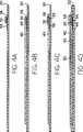
Nach
Beim nächsten Schritt wird in der Station
Die
Gemäß
Gemäß
Als nächstes wird ein Fleck leitenden Epoxyds auf jedes Ende des leitenden Streifens
Gemäß
Gemäß
Gemäß
Gemäß
Nachdem das in
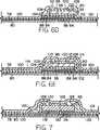
Nach
Gemäß
Bei dieser vierten Ausführungsform eines erfindungsgemäß hergestellten Bauelements dienen die gesamten äußeren Flächen der zwei Batterien
Nunmehr bezugnehmend auf eine fünfte Ausführungsform eines erfindungsgemäß hergestellten Bauelements, die perspektivisch in
Gemäß
Der Empfänger
Der Einsatzbereich eines mit einem erfindungsgemäßen Verfahren hergestellten HFID-Bauelements ist äußerst umfassend. Ohne Beschränkung seien hier als Beispiel angegeben: Lufttransportgüter (Gepäck, Fracht und Post); Paketdienst (Postdienst, privater Paketdienst); allgemeiner Postdienst; Fertigungstechnik, Inventurbereich; Personalsicherheit und Personal-Überwachung und dergleichen.The field of application of an HFID component produced by means of a method according to the invention is extremely extensive. By way of example, without limitation: air cargo (baggage, cargo and mail); Parcel service (postal service, private parcel service); general postal service; Production technology, inventory area; Personnel safety and personnel monitoring and the like.
Claims (17)
Translated fromGermanApplications Claiming Priority (2)
| Application Number | Priority Date | Filing Date | Title |
|---|---|---|---|
| US89977792A | 1992-06-17 | 1992-06-17 | |
| US07/899,777 | 1992-06-17 |
Publications (1)
| Publication Number | Publication Date |
|---|---|
| DE4345610B4true DE4345610B4 (en) | 2013-01-03 |
Family
ID=25411549
Family Applications (2)
| Application Number | Title | Priority Date | Filing Date |
|---|---|---|---|
| DE4345610AExpired - LifetimeDE4345610B4 (en) | 1992-06-17 | 1993-06-16 | Method for producing a radio-frequency identification device (HFID) |
| DE4319878ACeasedDE4319878A1 (en) | 1992-06-17 | 1993-06-16 | High frequency identification system card - has integrated circuit chip or carrier layer sealed by top layer and coupled to batteries and antenna system |
Family Applications After (1)
| Application Number | Title | Priority Date | Filing Date |
|---|---|---|---|
| DE4319878ACeasedDE4319878A1 (en) | 1992-06-17 | 1993-06-16 | High frequency identification system card - has integrated circuit chip or carrier layer sealed by top layer and coupled to batteries and antenna system |
Country Status (3)
| Country | Link |
|---|---|
| US (2) | US5448110A (en) |
| JP (1) | JP2857029B2 (en) |
| DE (2) | DE4345610B4 (en) |
Families Citing this family (372)
| Publication number | Priority date | Publication date | Assignee | Title |
|---|---|---|---|---|
| US5497140A (en)* | 1992-08-12 | 1996-03-05 | Micron Technology, Inc. | Electrically powered postage stamp or mailing or shipping label operative with radio frequency (RF) communication |
| US5572226A (en)* | 1992-05-15 | 1996-11-05 | Micron Technology, Inc. | Spherical antenna pattern(s) from antenna(s) arranged in a two-dimensional plane for use in RFID tags and labels |
| US5787174A (en)* | 1992-06-17 | 1998-07-28 | Micron Technology, Inc. | Remote identification of integrated circuit |
| US5776278A (en) | 1992-06-17 | 1998-07-07 | Micron Communications, Inc. | Method of manufacturing an enclosed transceiver |
| USRE42773E1 (en) | 1992-06-17 | 2011-10-04 | Round Rock Research, Llc | Method of manufacturing an enclosed transceiver |
| US6045652A (en)* | 1992-06-17 | 2000-04-04 | Micron Communications, Inc. | Method of manufacturing an enclosed transceiver |
| US5779839A (en)* | 1992-06-17 | 1998-07-14 | Micron Communications, Inc. | Method of manufacturing an enclosed transceiver |
| US7158031B2 (en)* | 1992-08-12 | 2007-01-02 | Micron Technology, Inc. | Thin, flexible, RFID label and system for use |
| US6058497A (en)* | 1992-11-20 | 2000-05-02 | Micron Technology, Inc. | Testing and burn-in of IC chips using radio frequency transmission |
| US5983363A (en) | 1992-11-20 | 1999-11-09 | Micron Communications, Inc. | In-sheet transceiver testing |
| US20050040961A1 (en)* | 1995-04-11 | 2005-02-24 | Tuttle John R. | RF identification system with restricted range |
| US6097301A (en)* | 1996-04-04 | 2000-08-01 | Micron Communications, Inc. | RF identification system with restricted range |
| US5983207A (en)* | 1993-02-10 | 1999-11-09 | Turk; James J. | Electronic cash eliminating payment risk |
| JPH0721336A (en)* | 1993-07-05 | 1995-01-24 | Mitsubishi Electric Corp | Contact type mobile device and non-contact type mobile device |
| US5790946A (en)* | 1993-07-15 | 1998-08-04 | Rotzoll; Robert R. | Wake up device for a communications system |
| DE4431754C1 (en)* | 1994-09-06 | 1995-11-23 | Siemens Ag | Carrier element for ic module of chip card |
| US5528222A (en)* | 1994-09-09 | 1996-06-18 | International Business Machines Corporation | Radio frequency circuit and memory in thin flexible package |
| US5682143A (en)* | 1994-09-09 | 1997-10-28 | International Business Machines Corporation | Radio frequency identification tag |
| TW280897B (en)* | 1994-10-27 | 1996-07-11 | Ibm | |
| JP2814477B2 (en)* | 1995-04-13 | 1998-10-22 | ソニーケミカル株式会社 | Non-contact IC card and method of manufacturing the same |
| US5761615A (en)* | 1995-05-31 | 1998-06-02 | Motorola, Inc. | Wide band zero if quadrature demodulator using a intermediate frequency and a single local oscillator |
| FR2735928B1 (en)* | 1995-06-22 | 1997-07-18 | France Telecom | MANCHESTER ENCODER / DECODER |
| US7511621B1 (en) | 1995-08-31 | 2009-03-31 | Intermec Ip Corp. | High-performance mobile power antennas |
| US6075441A (en) | 1996-09-05 | 2000-06-13 | Key-Trak, Inc. | Inventoriable-object control and tracking system |
| JP3378435B2 (en)* | 1995-09-29 | 2003-02-17 | 株式会社東芝 | Ultra-high frequency band wireless communication device |
| JP3528367B2 (en)* | 1995-09-30 | 2004-05-17 | ソニーケミカル株式会社 | Antenna for reader / writer |
| US5817207A (en) | 1995-10-17 | 1998-10-06 | Leighton; Keith R. | Radio frequency identification card and hot lamination process for the manufacture of radio frequency identification cards |
| US6441736B1 (en)* | 1999-07-01 | 2002-08-27 | Keith R. Leighton | Ultra-thin flexible durable radio frequency identification devices and hot or cold lamination process for the manufacture of ultra-thin flexible durable radio frequency identification devices |
| US6036099A (en) | 1995-10-17 | 2000-03-14 | Leighton; Keith | Hot lamination process for the manufacture of a combination contact/contactless smart card and product resulting therefrom |
| US5908135A (en)* | 1995-11-21 | 1999-06-01 | Bradford Company | Sleeve pack |
| US6169938B1 (en) | 1995-12-08 | 2001-01-02 | Marconi Commerce Systems Inc. | Transponder communication of ORVR presence |
| US6608464B1 (en)* | 1995-12-11 | 2003-08-19 | The Johns Hopkins University | Integrated power source layered with thin film rechargeable batteries, charger, and charge-control |
| US5644207A (en)* | 1995-12-11 | 1997-07-01 | The Johns Hopkins University | Integrated power source |
| DE19602821C1 (en)* | 1996-01-26 | 1997-06-26 | Siemens Ag | Method for producing a data card |
| GB9601899D0 (en)* | 1996-01-31 | 1996-04-03 | Neopost Ltd | Mailing system |
| US5987739A (en) | 1996-02-05 | 1999-11-23 | Micron Communications, Inc. | Method of making a polymer based circuit |
| US6215401B1 (en)* | 1996-03-25 | 2001-04-10 | Intermec Ip Corp. | Non-laminated coating for radio frequency transponder (RF tag) |
| US5786626A (en)* | 1996-03-25 | 1998-07-28 | Ibm Corporation | Thin radio frequency transponder with leadframe antenna structure |
| US5822683A (en)* | 1996-04-05 | 1998-10-13 | Ball Aerospace And Technologies Corp. | Pseudo-passive transponder device |
| JP3494800B2 (en)* | 1996-04-15 | 2004-02-09 | 和夫 坪内 | Wireless IC card system |
| WO1997039491A1 (en)* | 1996-04-16 | 1997-10-23 | The Johns Hopkins University | Integrated power source |
| FR2747812B1 (en)* | 1996-04-23 | 1998-05-22 | Solaic Sa | CONTACTLESS INTEGRATED CIRCUIT CARD WITH CONDUCTIVE POLYMER ANTENNA |
| KR100186412B1 (en)* | 1996-05-07 | 1999-04-15 | 구자홍 | Optical disc with built-in memory |
| US6696879B1 (en) | 1996-05-13 | 2004-02-24 | Micron Technology, Inc. | Radio frequency data communications device |
| US6130602A (en) | 1996-05-13 | 2000-10-10 | Micron Technology, Inc. | Radio frequency data communications device |
| US6774685B2 (en) | 1996-05-13 | 2004-08-10 | Micron Technology, Inc. | Radio frequency data communications device |
| US6941124B1 (en) | 1996-05-13 | 2005-09-06 | Micron Technology, Inc. | Method of speeding power-up of an amplifier, and amplifier |
| US6836468B1 (en) | 1996-05-13 | 2004-12-28 | Micron Technology, Inc. | Radio frequency data communications device |
| US5894266A (en)* | 1996-05-30 | 1999-04-13 | Micron Technology, Inc. | Method and apparatus for remote monitoring |
| US6466131B1 (en)* | 1996-07-30 | 2002-10-15 | Micron Technology, Inc. | Radio frequency data communications device with adjustable receiver sensitivity and method |
| US6061579A (en)* | 1996-09-06 | 2000-05-09 | Advanced Space Communications Research Laboratory | Hand-held mobile phone terminal |
| US5745036A (en)* | 1996-09-12 | 1998-04-28 | Checkpoint Systems, Inc. | Electronic article security system for store which uses intelligent security tags and transaction data |
| WO1998019339A1 (en)* | 1996-10-31 | 1998-05-07 | Sarnoff Corporation | Integrated electronic circuit |
| US5991602A (en)* | 1996-12-11 | 1999-11-23 | Labarge, Inc. | Method of and system for communication between points along a fluid flow |
| US6104333A (en) | 1996-12-19 | 2000-08-15 | Micron Technology, Inc. | Methods of processing wireless communication, methods of processing radio frequency communication, and related systems |
| DE19653409C2 (en)* | 1996-12-20 | 2001-05-03 | Claudia Weber | Mobile, machine-readable information carrier |
| US6084530A (en)* | 1996-12-30 | 2000-07-04 | Lucent Technologies Inc. | Modulated backscatter sensor system |
| US6184841B1 (en) | 1996-12-31 | 2001-02-06 | Lucent Technologies Inc. | Antenna array in an RFID system |
| US6456668B1 (en) | 1996-12-31 | 2002-09-24 | Lucent Technologies Inc. | QPSK modulated backscatter system |
| US6130623A (en)* | 1996-12-31 | 2000-10-10 | Lucent Technologies Inc. | Encryption for modulated backscatter systems |
| US6046683A (en)* | 1996-12-31 | 2000-04-04 | Lucent Technologies Inc. | Modulated backscatter location system |
| US6130612A (en)* | 1997-01-05 | 2000-10-10 | Intermec Ip Corp. | Antenna for RF tag with a magnetoelastic resonant core |
| US5988510A (en)* | 1997-02-13 | 1999-11-23 | Micron Communications, Inc. | Tamper resistant smart card and method of protecting data in a smart card |
| CA2197828C (en)* | 1997-02-18 | 2004-05-04 | Normand Dery | Thin-film antenna device for use with remote vehicle starting systems |
| FR2760113B1 (en)* | 1997-02-24 | 1999-06-04 | Gemplus Card Int | METHOD FOR MANUFACTURING A CONTACTLESS CARD WITH A COILED ANTENNA |
| US5914671A (en)* | 1997-02-27 | 1999-06-22 | Micron Communications, Inc. | System and method for locating individuals and equipment, airline reservation system, communication system |
| US7374081B2 (en)* | 1997-03-12 | 2008-05-20 | Precision Dynamics Corporation | Identification device having reusable transponder |
| US7198190B2 (en)* | 1997-03-12 | 2007-04-03 | Dodge Juhan | Identification device having reusable transponder |
| US6329213B1 (en) | 1997-05-01 | 2001-12-11 | Micron Technology, Inc. | Methods for forming integrated circuits within substrates |
| US6108798A (en)* | 1997-07-02 | 2000-08-22 | International Business Machines Corporation | Self programmed built in self test |
| US6230290B1 (en) | 1997-07-02 | 2001-05-08 | International Business Machines Corporation | Method of self programmed built in self test |
| US5764655A (en)* | 1997-07-02 | 1998-06-09 | International Business Machines Corporation | Built in self test with memory |
| US5963134A (en) | 1997-07-24 | 1999-10-05 | Checkpoint Systems, Inc. | Inventory system using articles with RFID tags |
| US6025780A (en)* | 1997-07-25 | 2000-02-15 | Checkpoint Systems, Inc. | RFID tags which are virtually activated and/or deactivated and apparatus and methods of using same in an electronic security system |
| US5971587A (en)* | 1997-08-01 | 1999-10-26 | Kato; Kiroku | Package and mail delivery system |
| US6057779A (en)* | 1997-08-14 | 2000-05-02 | Micron Technology, Inc. | Method of controlling access to a movable container and to a compartment of a vehicle, and a secure cargo transportation system |
| US6980085B1 (en)* | 1997-08-18 | 2005-12-27 | Micron Technology, Inc. | Wireless communication devices and methods of forming and operating the same |
| US6339385B1 (en)* | 1997-08-20 | 2002-01-15 | Micron Technology, Inc. | Electronic communication devices, methods of forming electrical communication devices, and communication methods |
| US6073840A (en) | 1997-09-26 | 2000-06-13 | Gilbarco Inc. | Fuel dispensing and retail system providing for transponder prepayment |
| US6810304B1 (en)* | 1997-09-26 | 2004-10-26 | Gilbarco Inc. | Multistage ordering system for a fueling and retail environment |
| US6070156A (en)* | 1997-09-26 | 2000-05-30 | Gilbarco Inc. | Providing transaction estimates in a fueling and retail system |
| US6037879A (en) | 1997-10-02 | 2000-03-14 | Micron Technology, Inc. | Wireless identification device, RFID device, and method of manufacturing wireless identification device |
| US6768415B1 (en) | 1997-10-03 | 2004-07-27 | Micron Technology, Inc. | Wireless identification device, RFID device with push-on/push-off switch, method of manufacturing wireless identification device |
| US7012504B2 (en)* | 2002-04-01 | 2006-03-14 | Micron Technology, Inc. | Wireless identification device, RFID device with push-on/push off switch, and method of manufacturing wireless identification device |
| US6593845B1 (en) | 1998-01-09 | 2003-07-15 | Intermac Ip Corp. | Active RF tag with wake-up circuit to prolong battery life |
| GB2333207B (en)* | 1998-01-09 | 2003-06-11 | Peter George Milton | Monitoring reels of paper for use on printing presses |
| US6119255A (en) | 1998-01-21 | 2000-09-12 | Micron Technology, Inc. | Testing system for evaluating integrated circuits, a burn-in testing system, and a method for testing an integrated circuit |
| US6356535B1 (en)* | 1998-02-04 | 2002-03-12 | Micron Technology, Inc. | Communication systems and methods of communicating |
| US6030423A (en)* | 1998-02-12 | 2000-02-29 | Micron Technology, Inc. | Thin profile battery bonding method and method of conductively interconnecting electronic components |
| US6571151B1 (en) | 1998-03-06 | 2003-05-27 | Russel Dean Leatherman | Wireless nozzle interface for a fuel dispenser |
| US6342839B1 (en)* | 1998-03-09 | 2002-01-29 | Aginfolink Holdings Inc. | Method and apparatus for a livestock data collection and management system |
| US6320509B1 (en) | 1998-03-16 | 2001-11-20 | Intermec Ip Corp. | Radio frequency identification transponder having a high gain antenna configuration |
| US6459726B1 (en)* | 1998-04-24 | 2002-10-01 | Micron Technology, Inc. | Backscatter interrogators, communication systems and backscatter communication methods |
| FR2778475B1 (en)* | 1998-05-11 | 2001-11-23 | Schlumberger Systems & Service | NON-CONTACT TYPE MEMORY CARD, AND METHOD FOR MANUFACTURING SUCH A CARD |
| FR2778769B1 (en)* | 1998-05-15 | 2001-11-02 | Gemplus Sca | INTEGRATED CIRCUIT CARD INCLUDING AN INTERFACE TERMINAL BLOCK AND PROCESS FOR MANUFACTURING SUCH A CARD |
| US6154137A (en) | 1998-06-08 | 2000-11-28 | 3M Innovative Properties Company | Identification tag with enhanced security |
| US6185712B1 (en) | 1998-07-02 | 2001-02-06 | International Business Machines Corporation | Chip performance optimization with self programmed built in self test |
| WO2000002236A2 (en) | 1998-07-07 | 2000-01-13 | Memc Electronic Materials, Inc. | Radio frequency identification system and method for tracking silicon wafers |
| AU5104399A (en)* | 1998-07-20 | 2000-02-07 | William Neil Jones | A method of individually tracking and identifying a drug delivery device |
| US6251211B1 (en) | 1998-07-22 | 2001-06-26 | Micron Technology, Inc. | Circuitry interconnection method |
| JP2002522999A (en) | 1998-08-14 | 2002-07-23 | スリーエム イノベイティブ プロパティズ カンパニー | Applications to radio frequency identification systems |
| US6424262B2 (en) | 1998-08-14 | 2002-07-23 | 3M Innovative Properties Company | Applications for radio frequency identification systems |
| KR100699755B1 (en) | 1998-08-14 | 2007-03-27 | 쓰리엠 이노베이티브 프로퍼티즈 캄파니 | Radio Frequency Identification System Applications |
| EP1770592B1 (en) | 1998-08-14 | 2009-10-07 | 3M Innovative Properties Company | Method of interrogating a package bearing an RFID tag |
| EP1112558A4 (en) | 1998-09-11 | 2002-07-31 | Key Trak Inc | Object tracking system with non-contact object detection and identification |
| US6262664B1 (en) | 1998-09-11 | 2001-07-17 | Key-Trak, Inc. | Tamper detection prevention for an object control and tracking system |
| AU5916899A (en)* | 1998-09-11 | 2000-04-03 | Key-Trak, Inc. | Objet carriers for an object control and tracking system |
| US6891473B2 (en)* | 1998-09-11 | 2005-05-10 | Key-Trak, Inc. | Object carriers and lighted tags for an object control and tracking system |
| AU6032699A (en)* | 1998-09-11 | 2000-04-03 | Key-Trak, Inc. | Mobile object tracking system |
| CA2343412A1 (en) | 1998-09-11 | 2000-03-23 | William C. Maloney | Object control and tracking system with zonal transition detection |
| DE19842366A1 (en)* | 1998-09-14 | 2000-03-16 | Bsh Bosch Siemens Hausgeraete | Electronic transponder communicating care advice for textiles is attached together with care label in simple operation and permits e.g. reader-equipped washing machine to select correct cycle autonomously |
| JP4340929B2 (en)* | 1998-10-02 | 2009-10-07 | ソニー株式会社 | Memory IC tag device |
| US6147604A (en)* | 1998-10-15 | 2000-11-14 | Intermec Ip Corporation | Wireless memory device |
| US6366260B1 (en)* | 1998-11-02 | 2002-04-02 | Intermec Ip Corp. | RFID tag employing hollowed monopole antenna |
| JP2006085729A (en)* | 1998-11-30 | 2006-03-30 | Hitachi Ltd | Mounting method of electronic circuit chip |
| MY119951A (en) | 1998-12-09 | 2005-08-30 | Shell Int Research | Transponder communications system |
| FR2787260B1 (en)* | 1998-12-09 | 2003-01-24 | Gemplus Card Int | ELECTRONIC CONTACTLESS COMMUNICATION DEVICE WITH OPTIONAL AUXILIARY ENERGY SOURCE |
| US6246882B1 (en) | 1998-12-22 | 2001-06-12 | Telefonaktiebolaget Lm Ericsson (Publ) | Wide area item tracking system |
| US6379835B1 (en) | 1999-01-12 | 2002-04-30 | Morgan Adhesives Company | Method of making a thin film battery |
| US6433728B1 (en)* | 1999-01-22 | 2002-08-13 | Lear Automotive Dearborn, Inc. | Integrally molded remote entry transmitter |
| US10973397B2 (en) | 1999-03-01 | 2021-04-13 | West View Research, Llc | Computerized information collection and processing apparatus |
| US6542720B1 (en) | 1999-03-01 | 2003-04-01 | Micron Technology, Inc. | Microelectronic devices, methods of operating microelectronic devices, and methods of providing microelectronic devices |
| US8636648B2 (en) | 1999-03-01 | 2014-01-28 | West View Research, Llc | Endoscopic smart probe |
| US6468638B2 (en)* | 1999-03-16 | 2002-10-22 | Alien Technology Corporation | Web process interconnect in electronic assemblies |
| JP3258972B2 (en)* | 1999-03-18 | 2002-02-18 | 三洋電機株式会社 | Portable wireless communication device |
| US6278413B1 (en) | 1999-03-29 | 2001-08-21 | Intermec Ip Corporation | Antenna structure for wireless communications device, such as RFID tag |
| US8065155B1 (en) | 1999-06-10 | 2011-11-22 | Gazdzinski Robert F | Adaptive advertising apparatus and methods |
| US6994262B1 (en)* | 1999-06-16 | 2006-02-07 | Vanguard Identification Systems, Inc. | Printed sheet products with integral, removable, radio frequency identification elements |
| US8654018B2 (en)* | 2005-04-06 | 2014-02-18 | Vanguard Identificaiton Systems, Inc. | Printed planar RFID element wristbands and like personal identification devices |
| US8585852B2 (en)* | 1999-06-16 | 2013-11-19 | Vanguard Identification Systems, Inc. | Methods of making printed planar radio frequency identification elements |
| US6784789B2 (en)* | 1999-07-08 | 2004-08-31 | Intermec Ip Corp. | Method and apparatus for verifying RFID tags |
| US6714121B1 (en) | 1999-08-09 | 2004-03-30 | Micron Technology, Inc. | RFID material tracking method and apparatus |
| US6273339B1 (en) | 1999-08-30 | 2001-08-14 | Micron Technology, Inc. | Tamper resistant smart card and method of protecting data in a smart card |
| US7710273B2 (en)* | 1999-09-02 | 2010-05-04 | Round Rock Research, Llc | Remote communication devices, radio frequency identification devices, wireless communication systems, wireless communication methods, radio frequency identification device communication methods, and methods of forming a remote communication device |
| EP1287424A2 (en)* | 1999-09-03 | 2003-03-05 | Marathon Products Inc. | Method and system for procuring, storing and distributing remotely accessed data gathered by logging devices |
| US6259408B1 (en) | 1999-11-19 | 2001-07-10 | Intermec Ip Corp. | RFID transponders with paste antennas and flip-chip attachment |
| US6520544B1 (en) | 2000-01-10 | 2003-02-18 | Moore North America, Inc. | Radio frequency labels on reusable containers |
| US7342496B2 (en) | 2000-01-24 | 2008-03-11 | Nextreme Llc | RF-enabled pallet |
| US8077040B2 (en) | 2000-01-24 | 2011-12-13 | Nextreme, Llc | RF-enabled pallet |
| US6943678B2 (en) | 2000-01-24 | 2005-09-13 | Nextreme, L.L.C. | Thermoformed apparatus having a communications device |
| US6661339B2 (en) | 2000-01-24 | 2003-12-09 | Nextreme, L.L.C. | High performance fuel tank |
| US6451154B1 (en)* | 2000-02-18 | 2002-09-17 | Moore North America, Inc. | RFID manufacturing concepts |
| US6262662B1 (en)* | 2000-02-25 | 2001-07-17 | Xerox Corporation | Systems and methods that detect proximity information using electric field sensing devices and a page identification using embedded identification tags |
| GB0004456D0 (en)* | 2000-02-26 | 2000-04-19 | Glaxo Group Ltd | Medicament dispenser |
| US6962613B2 (en)* | 2000-03-24 | 2005-11-08 | Cymbet Corporation | Low-temperature fabrication of thin-film energy-storage devices |
| US6369710B1 (en) | 2000-03-27 | 2002-04-09 | Lucent Technologies Inc. | Wireless security system |
| DE10015732A1 (en)* | 2000-03-29 | 2001-10-11 | Skidata Ag | Access authorization booking process |
| AU2001253581A1 (en)* | 2000-04-17 | 2001-10-30 | International Paper | Tax stamp authentication and product control |
| US6806812B1 (en)* | 2000-04-26 | 2004-10-19 | Micron Technology, Inc. | Automated antenna trim for transmitting and receiving semiconductor devices |
| DE10052517B4 (en)* | 2000-04-28 | 2009-01-02 | Multitape Gmbh | Transponder module, identification carrier and method for producing a transponder module |
| US6603400B1 (en)* | 2000-05-04 | 2003-08-05 | Telxon Corporation | Paper capacitor |
| GB0012465D0 (en) | 2000-05-24 | 2000-07-12 | Glaxo Group Ltd | Monitoring method |
| JP3398126B2 (en)* | 2000-06-05 | 2003-04-21 | 株式会社九北エレクトロニクス | Article identification device |
| GB0013619D0 (en)* | 2000-06-06 | 2000-07-26 | Glaxo Group Ltd | Sample container |
| HK1056125A1 (en)* | 2000-07-15 | 2004-02-06 | Glaxo Group Limited | Medicament dispenser |
| US6714136B1 (en)* | 2000-08-14 | 2004-03-30 | Computime, Ltd. | Alarm clock with remote control function |
| US6486783B1 (en) | 2000-09-19 | 2002-11-26 | Moore North America, Inc. | RFID composite for mounting on or adjacent metal objects |
| US6392544B1 (en)* | 2000-09-25 | 2002-05-21 | Motorola, Inc. | Method and apparatus for selectively activating radio frequency identification tags that are in close proximity |
| US6975834B1 (en)* | 2000-10-03 | 2005-12-13 | Mineral Lassen Llc | Multi-band wireless communication device and method |
| EP1213877A1 (en)* | 2000-12-11 | 2002-06-12 | Siemens Aktiengesellschaft | High integrated electrical circuit and method for exchanging data in a closed system |
| US6749581B2 (en) | 2001-02-02 | 2004-06-15 | Medtronic, Inc. | Variable infusion rate catheter |
| US6562000B2 (en) | 2001-02-02 | 2003-05-13 | Medtronic, Inc. | Single-use therapeutic substance delivery device with infusion rate control |
| US6853447B2 (en)* | 2001-02-12 | 2005-02-08 | Analytical Spectral Devices, Inc. | System and method for the collection of spectral image data |
| US6894772B2 (en)* | 2001-02-12 | 2005-05-17 | Analytical Spectral Devices | System and method for grouping reflectance data |
| US7017822B2 (en)* | 2001-02-15 | 2006-03-28 | Integral Technologies, Inc. | Low cost RFID antenna manufactured from conductive loaded resin-based materials |
| DE10109221B4 (en)* | 2001-02-26 | 2011-04-14 | Infineon Technologies Ag | Method for producing a self-powered, contactless data carrier |
| US20020130817A1 (en)* | 2001-03-16 | 2002-09-19 | Forster Ian J. | Communicating with stackable objects using an antenna array |
| CN1266644C (en)* | 2001-03-16 | 2006-07-26 | 皇家菲利浦电子有限公司 | Portable electronic device |
| US6779246B2 (en) | 2001-04-23 | 2004-08-24 | Appleton Papers Inc. | Method and system for forming RF reflective pathways |
| US6892441B2 (en)* | 2001-04-23 | 2005-05-17 | Appleton Papers Inc. | Method for forming electrically conductive pathways |
| US7376234B1 (en) | 2001-05-14 | 2008-05-20 | Hand Held Products, Inc. | Portable keying device and method |
| US6606247B2 (en)* | 2001-05-31 | 2003-08-12 | Alien Technology Corporation | Multi-feature-size electronic structures |
| US20020183009A1 (en)* | 2001-06-01 | 2002-12-05 | Cruz-Albrecht Jose M. | Radio communication within a computer system |
| US7588185B2 (en) | 2001-06-07 | 2009-09-15 | 3M Innovative Properties Company | RFID data collection and use |
| WO2002103384A1 (en)* | 2001-06-19 | 2002-12-27 | Star Bt Limited | Location, communication and tracking systems |
| US6707381B1 (en)* | 2001-06-26 | 2004-03-16 | Key-Trak, Inc. | Object tracking method and system with object identification and verification |
| CN1276386C (en)* | 2001-06-27 | 2006-09-20 | 皇家菲利浦电子有限公司 | Data carrier with integrated circuit between two carrier layers |
| JP3671881B2 (en)* | 2001-07-18 | 2005-07-13 | ソニー株式会社 | COMMUNICATION SYSTEM AND METHOD, INFORMATION PROCESSING DEVICE AND METHOD, COMMUNICATION TERMINAL AND METHOD, EXPANSION DEVICE, AND PROGRAM |
| DE10139383B4 (en)* | 2001-08-10 | 2006-06-01 | Infineon Technologies Ag | chip module |
| US6993298B2 (en)* | 2001-09-07 | 2006-01-31 | Siemens Energy & Automation, Inc. | Programmable controller with RF wireless interface |
| JP3975069B2 (en)* | 2001-10-25 | 2007-09-12 | 株式会社エヌ・ティ・ティ・ドコモ | Radio base station and radio communication control method |
| US7177601B1 (en)* | 2001-11-02 | 2007-02-13 | Raytheon Company | Method and apparatus for transceiving data using a bimodal power data link transceiver device |
| DE10156073B4 (en)* | 2001-11-16 | 2008-08-21 | Giesecke & Devrient Gmbh | Foil battery for portable data carriers with antenna function |
| DE10158195B4 (en)* | 2001-11-28 | 2005-04-28 | Orga Kartensysteme Gmbh | Chip card and a method for producing a chip card |
| US20150127434A1 (en)* | 2002-01-04 | 2015-05-07 | Prova Group, Inc. | Event display system and method |
| US7214569B2 (en)* | 2002-01-23 | 2007-05-08 | Alien Technology Corporation | Apparatus incorporating small-feature-size and large-feature-size components and method for making same |
| JP2003243922A (en)* | 2002-02-15 | 2003-08-29 | Toyota Central Res & Dev Lab Inc | Antenna device |
| GB2388744A (en)* | 2002-03-01 | 2003-11-19 | Btg Int Ltd | An RFID tag |
| US6771369B2 (en)* | 2002-03-12 | 2004-08-03 | Analytical Spectral Devices, Inc. | System and method for pharmacy validation and inspection |
| DE10214875B4 (en)* | 2002-04-04 | 2005-12-08 | Giesecke & Devrient Gmbh | Planar portable data carrier |
| AU2003233007A1 (en) | 2002-04-24 | 2003-11-10 | Marconi Intellectual Property (Us) Inc | Energy source with a slot antenna formed in the body |
| WO2003091746A1 (en)* | 2002-04-24 | 2003-11-06 | Marconi Intellectual Property (Us) Inc | Rechargeable interrogation reader device and method |
| WO2003091943A1 (en)* | 2002-04-24 | 2003-11-06 | Marconi Intellectual Property (Us) Inc | Energy source recharging device and method |
| US20030222755A1 (en)* | 2002-05-31 | 2003-12-04 | Kemper Jonathan Thomas | Credit card sized remote control transmitter application |
| US20050043886A1 (en)* | 2002-06-06 | 2005-02-24 | John Stevens | Delivery system and method for low visibilty conditions |
| US7009576B2 (en)* | 2002-06-11 | 2006-03-07 | Michelin Recherche Et Technique S.A. | Radio frequency antenna for a tire and method for same |
| JP2004056563A (en)* | 2002-07-22 | 2004-02-19 | Matsushita Electric Ind Co Ltd | Mobile phone |
| US7993773B2 (en) | 2002-08-09 | 2011-08-09 | Infinite Power Solutions, Inc. | Electrochemical apparatus with barrier layer protected substrate |
| US8431264B2 (en) | 2002-08-09 | 2013-04-30 | Infinite Power Solutions, Inc. | Hybrid thin-film battery |
| US8445130B2 (en) | 2002-08-09 | 2013-05-21 | Infinite Power Solutions, Inc. | Hybrid thin-film battery |
| US8404376B2 (en) | 2002-08-09 | 2013-03-26 | Infinite Power Solutions, Inc. | Metal film encapsulation |
| US8236443B2 (en) | 2002-08-09 | 2012-08-07 | Infinite Power Solutions, Inc. | Metal film encapsulation |
| US8394522B2 (en) | 2002-08-09 | 2013-03-12 | Infinite Power Solutions, Inc. | Robust metal film encapsulation |
| US8021778B2 (en) | 2002-08-09 | 2011-09-20 | Infinite Power Solutions, Inc. | Electrochemical apparatus with barrier layer protected substrate |
| US20070264564A1 (en) | 2006-03-16 | 2007-11-15 | Infinite Power Solutions, Inc. | Thin film battery on an integrated circuit or circuit board and method thereof |
| US7573370B2 (en)* | 2002-09-05 | 2009-08-11 | Honeywell International Inc. | Method and device for storing and distributing information in an RFID tag |
| US6667092B1 (en) | 2002-09-26 | 2003-12-23 | International Paper Company | RFID enabled corrugated structures |
| US7088964B2 (en)* | 2002-10-02 | 2006-08-08 | University Of Florida Research Foundation, Inc. | Single chip radio with integrated antenna |
| US20040229560A1 (en)* | 2002-10-10 | 2004-11-18 | Maloney William C. | Methods of tracking and verifying human assets |
| US20040131760A1 (en)* | 2003-01-02 | 2004-07-08 | Stuart Shakespeare | Apparatus and method for depositing material onto multiple independently moving substrates in a chamber |
| US7603144B2 (en) | 2003-01-02 | 2009-10-13 | Cymbet Corporation | Active wireless tagging system on peel and stick substrate |
| US6906436B2 (en) | 2003-01-02 | 2005-06-14 | Cymbet Corporation | Solid state activity-activated battery device and method |
| US7294209B2 (en) | 2003-01-02 | 2007-11-13 | Cymbet Corporation | Apparatus and method for depositing material onto a substrate using a roll-to-roll mask |
| US7106173B2 (en)* | 2003-01-03 | 2006-09-12 | Battelle Memorial Institute | Tags, wireless communication systems, tag communication methods, and wireless communications methods |
| US7091841B2 (en)* | 2003-02-19 | 2006-08-15 | Michelin Recherche Et Technique, S.A. | Tire electronics assembly having a multi-frequency antenna |
| EP1615784B1 (en)* | 2003-02-19 | 2011-01-19 | Société de Technologie Michelin | Tire electronics assembly having a multi-frequency antenna |
| EP1465279A1 (en)* | 2003-03-15 | 2004-10-06 | Orga Kartensysteme GmbH | Thin film battery as body of a chip card |
| US7253735B2 (en)* | 2003-03-24 | 2007-08-07 | Alien Technology Corporation | RFID tags and processes for producing RFID tags |
| US7501984B2 (en)* | 2003-11-04 | 2009-03-10 | Avery Dennison Corporation | RFID tag using a surface insensitive antenna structure |
| US7652636B2 (en)* | 2003-04-10 | 2010-01-26 | Avery Dennison Corporation | RFID devices having self-compensating antennas and conductive shields |
| US6914562B2 (en)* | 2003-04-10 | 2005-07-05 | Avery Dennison Corporation | RFID tag using a surface insensitive antenna structure |
| DE10318052A1 (en)* | 2003-04-17 | 2004-11-04 | Giesecke & Devrient Gmbh | Portable data carrier and method for communicating with a portable data carrier |
| JP2006524402A (en)* | 2003-04-21 | 2006-10-26 | シンボル テクノロジーズ インコーポレイテッド | Method for optimizing the design and implementation of RFID tags |
| JP2004328263A (en)* | 2003-04-23 | 2004-11-18 | Mitsubishi Electric Corp | DSRC OBE |
| US20040238623A1 (en)* | 2003-05-09 | 2004-12-02 | Wayne Asp | Component handling device having a film insert molded RFID tag |
| DE10323168A1 (en)* | 2003-05-22 | 2004-12-09 | Conti Temic Microelectronic Gmbh | Labeling element for an electronic component, e.g. for storage of component specific information, comprises a memory and antenna that permits reading from or writing to the memory via electromagnetic waves |
| US8728285B2 (en) | 2003-05-23 | 2014-05-20 | Demaray, Llc | Transparent conductive oxides |
| AU2003257668A1 (en)* | 2003-08-22 | 2005-03-10 | Ykk Corporation | Fastener and fitted body having the fastener |
| US7042413B2 (en)* | 2003-08-22 | 2006-05-09 | Checkpoint Systems, Inc. | Security tag with three dimensional antenna array made from flat stock |
| US7149482B2 (en)* | 2003-09-16 | 2006-12-12 | Andrew Corporation | Compensation of filters in radio transmitters |
| US7230321B2 (en)* | 2003-10-13 | 2007-06-12 | Mccain Joseph | Integrated circuit package with laminated power cell having coplanar electrode |
| US7557433B2 (en)* | 2004-10-25 | 2009-07-07 | Mccain Joseph H | Microelectronic device with integrated energy source |
| US7211351B2 (en) | 2003-10-16 | 2007-05-01 | Cymbet Corporation | Lithium/air batteries with LiPON as separator and protective barrier and method |
| US7138955B2 (en)* | 2003-10-23 | 2006-11-21 | Michelin Recherche Et Technique S.A. | Robust antenna connection for an electronics component assembly in a tire |
| US7184289B2 (en)* | 2003-11-12 | 2007-02-27 | Intel Corporation | Parallel electrode memory |
| US7325180B2 (en)* | 2003-11-26 | 2008-01-29 | Carnegie Mellon University | System and method to test integrated circuits on a wafer |
| JP2005229098A (en)* | 2003-12-12 | 2005-08-25 | Semiconductor Energy Lab Co Ltd | Semiconductor device and manufacturing method thereof |
| US7768405B2 (en) | 2003-12-12 | 2010-08-03 | Semiconductor Energy Laboratory Co., Ltd | Semiconductor device and manufacturing method thereof |
| US7427024B1 (en) | 2003-12-17 | 2008-09-23 | Gazdzinski Mark J | Chattel management apparatus and methods |
| US7494742B2 (en) | 2004-01-06 | 2009-02-24 | Cymbet Corporation | Layered barrier structure having one or more definable layers and method |
| US20050176376A1 (en)* | 2004-02-11 | 2005-08-11 | Accton Technology Corporation | Batch testing system and method for wireless communication devices |
| US7755484B2 (en)* | 2004-02-12 | 2010-07-13 | Avery Dennison Corporation | RFID tag and method of manufacturing the same |
| US7384496B2 (en)* | 2004-02-23 | 2008-06-10 | Checkpoint Systems, Inc. | Security tag system for fabricating a tag including an integrated surface processing system |
| USD587691S1 (en) | 2004-03-29 | 2009-03-03 | Impinj, Inc. | Radio frequency identification tag antenna assembly |
| US7667589B2 (en)* | 2004-03-29 | 2010-02-23 | Impinj, Inc. | RFID tag uncoupling one of its antenna ports and methods |
| US7528728B2 (en)* | 2004-03-29 | 2009-05-05 | Impinj Inc. | Circuits for RFID tags with multiple non-independently driven RF ports |
| US7423539B2 (en)* | 2004-03-31 | 2008-09-09 | Impinj, Inc. | RFID tags combining signals received from multiple RF ports |
| US7165728B2 (en)* | 2004-04-02 | 2007-01-23 | Stratos International, Inc. | Radio frequency identification for transfer of component information in fiber optic testing |
| US7243837B2 (en)* | 2004-04-02 | 2007-07-17 | Stratos International, Inc. | Media converter RFID security tag |
| US20050224585A1 (en)* | 2004-04-02 | 2005-10-13 | Durrant Richard C E | Radio frequency identification of a connector by a patch panel or other similar structure |
| US7674117B2 (en)* | 2004-04-19 | 2010-03-09 | Michelin Recherche Et Technique S.A. | Strain-resistant electrical connection |
| US7196617B2 (en)* | 2004-04-19 | 2007-03-27 | Michelin Recherche Et Technique S.A. | Graduated stiffness for electrical connections in tires |
| JP4020096B2 (en) | 2004-05-11 | 2007-12-12 | ソニー株式会社 | Wireless communication system, wireless communication apparatus, and wireless communication method |
| DE202004007819U1 (en)* | 2004-05-13 | 2005-07-14 | Siemens Ag | Mobile data carrier or read-write device with an antenna arrangement with adjustable characteristics, and associated transport device |
| US20060012387A1 (en)* | 2004-06-29 | 2006-01-19 | Symbol Technologies, Inc. | Systems and methods for testing radio frequency identification tags |
| US7501955B2 (en)* | 2004-09-13 | 2009-03-10 | Avery Dennison Corporation | RFID device with content insensitivity and position insensitivity |
| US7353598B2 (en) | 2004-11-08 | 2008-04-08 | Alien Technology Corporation | Assembly comprising functional devices and method of making same |
| US7452748B1 (en) | 2004-11-08 | 2008-11-18 | Alien Technology Corporation | Strap assembly comprising functional block deposited therein and method of making same |
| US7551141B1 (en) | 2004-11-08 | 2009-06-23 | Alien Technology Corporation | RFID strap capacitively coupled and method of making same |
| KR101038493B1 (en)* | 2004-11-12 | 2011-06-01 | 삼성테크윈 주식회사 | Method for manufacturing radio frequency recognition tag for microwave |
| US20060109118A1 (en)* | 2004-11-22 | 2006-05-25 | Sdgi Holdings, Inc. | Twist-tie RFID tag |
| US7385284B2 (en)* | 2004-11-22 | 2008-06-10 | Alien Technology Corporation | Transponder incorporated into an electronic device |
| US7688206B2 (en) | 2004-11-22 | 2010-03-30 | Alien Technology Corporation | Radio frequency identification (RFID) tag for an item having a conductive layer included or attached |
| US20060122851A1 (en)* | 2004-12-03 | 2006-06-08 | Pitney Bowes Incorporated | Method and system for communicating delivery information in a mail distribution system |
| US20060121851A1 (en)* | 2004-12-06 | 2006-06-08 | Steve Moore | Ultra-wideband security system |
| KR101127370B1 (en) | 2004-12-08 | 2012-03-29 | 인피니트 파워 솔루션스, 인크. | Deposition of licoo2 |
| US7959769B2 (en) | 2004-12-08 | 2011-06-14 | Infinite Power Solutions, Inc. | Deposition of LiCoO2 |
| US7546137B2 (en)* | 2005-02-28 | 2009-06-09 | Sirit Technologies Inc. | Power control loop and LO generation method |
| US7279920B2 (en)* | 2005-04-06 | 2007-10-09 | Texas Instruments Incoporated | Expeditious and low cost testing of RFID ICs |
| US7760104B2 (en)* | 2005-04-08 | 2010-07-20 | Entegris, Inc. | Identification tag for fluid containment drum |
| DE102005018803A1 (en)* | 2005-04-22 | 2006-10-26 | Mühlbauer Ag | Transponder for ultra-high frequency radio frequency identification system, has dipole antenna conductor section having two parts with two sets of regions joined by conductive adhesives and made of low-impedance and high-impedance materials |
| US7542301B1 (en) | 2005-06-22 | 2009-06-02 | Alien Technology Corporation | Creating recessed regions in a substrate and assemblies having such recessed regions |
| GB2427760B (en)* | 2005-06-27 | 2010-01-20 | Samsung Electronics Co Ltd | Antenna-transceiver system |
| US7931989B2 (en) | 2005-07-15 | 2011-04-26 | Cymbet Corporation | Thin-film batteries with soft and hard electrolyte layers and method |
| US20070012244A1 (en)* | 2005-07-15 | 2007-01-18 | Cymbet Corporation | Apparatus and method for making thin-film batteries with soft and hard electrolyte layers |
| US7776478B2 (en) | 2005-07-15 | 2010-08-17 | Cymbet Corporation | Thin-film batteries with polymer and LiPON electrolyte layers and method |
| US20070013487A1 (en)* | 2005-07-18 | 2007-01-18 | Jan Scholtz | Digital certificate on connectors and other products using RFID tags and/or labels as well as RFID reader/interrogator |
| US20070018813A1 (en)* | 2005-07-22 | 2007-01-25 | Liggitt Richard C | Electronic identification tag |
| US7893813B2 (en)* | 2005-07-28 | 2011-02-22 | Intermec Ip Corp. | Automatic data collection device, method and article |
| US20070031992A1 (en)* | 2005-08-05 | 2007-02-08 | Schatz Kenneth D | Apparatuses and methods facilitating functional block deposition |
| DE102005042444B4 (en)* | 2005-09-06 | 2007-10-11 | Ksw Microtec Ag | Arrangement for an RFID transponder antenna |
| US7336883B2 (en)* | 2005-09-08 | 2008-02-26 | Stratos International, Inc. | Indexing optical fiber adapter |
| WO2007035863A2 (en) | 2005-09-21 | 2007-03-29 | Intermec Ip Corp. | Radio frequency identification tags based on coalition formation |
| US8753097B2 (en) | 2005-11-21 | 2014-06-17 | Entegris, Inc. | Method and system for high viscosity pump |
| CN101390251B (en)* | 2006-02-24 | 2013-06-19 | Nxp股份有限公司 | Transmitter, receiver, antenna arrangement for use with a transmitter or for use with a receiver, and RFID transponder |
| EP2000958A2 (en)* | 2006-03-30 | 2008-12-10 | Oji Paper Company Limited | Ic module, ic inlet and ic mounted body |
| US7854639B1 (en)* | 2006-03-31 | 2010-12-21 | Eloy Leal | Flotation assembly with monitoring device |
| US8120461B2 (en) | 2006-04-03 | 2012-02-21 | Intermec Ip Corp. | Automatic data collection device, method and article |
| WO2007118035A2 (en)* | 2006-04-03 | 2007-10-18 | 3M Innovative Properties Company | Tamper-evident life vest package |
| US20080108261A1 (en)* | 2006-04-03 | 2008-05-08 | 3M Innovative Properties Company | Human floatation device configured for radio frequency identification |
| US20070229268A1 (en)* | 2006-04-03 | 2007-10-04 | 3M Innovative Properties Company | Vehicle inspection using radio frequency identification (rfid) |
| KR100843887B1 (en)* | 2006-06-02 | 2008-07-03 | 주식회사 하이닉스반도체 | Integrated circuits and information recording methods |
| US8917178B2 (en)* | 2006-06-09 | 2014-12-23 | Dominic M. Kotab | RFID system and method for storing information related to a vehicle or an owner of the vehicle |
| US8002173B2 (en) | 2006-07-11 | 2011-08-23 | Intermec Ip Corp. | Automatic data collection device, method and article |
| US7724145B2 (en)* | 2006-07-20 | 2010-05-25 | Intelleflex Corporation | Self-charging RFID tag with long life |
| US7579955B2 (en) | 2006-08-11 | 2009-08-25 | Intermec Ip Corp. | Device and method for selective backscattering of wireless communications signals |
| US8344888B2 (en)* | 2006-08-31 | 2013-01-01 | Semiconductor Energy Laboratory Co., Ltd. | Semiconductor device |
| JP2010505044A (en) | 2006-09-29 | 2010-02-18 | インフィニット パワー ソリューションズ, インコーポレイテッド | Material constraints for masking flexible substrates and depositing battery layers on flexible substrates |
| US20080106418A1 (en)* | 2006-11-02 | 2008-05-08 | Symbol Technologies, Inc. | RFID tag using patch antenna designs and low cost manufacturing techniques |
| US8197781B2 (en) | 2006-11-07 | 2012-06-12 | Infinite Power Solutions, Inc. | Sputtering target of Li3PO4 and method for producing same |
| DE102006059745A1 (en)* | 2006-12-18 | 2008-06-19 | Grammer Ag | Air spring for a vehicle seat and vehicle seat with such an air spring |
| EP1939794A3 (en) | 2006-12-29 | 2009-04-01 | Vanguard Identification Systems, Inc. | Printed planar RFID element wristbands and like personal identification devices |
| US7616120B1 (en) | 2007-02-28 | 2009-11-10 | Impinj, Inc. | Multiple RF-port modulator for RFID tag |
| US20080212303A1 (en)* | 2007-03-02 | 2008-09-04 | Warren Farnworth | Device for reducing or preventing exchange of information |
| DE102007019365B4 (en) | 2007-04-23 | 2013-04-11 | Grammer Aktiengesellschaft | Method and device for evaluating vibrations of a vehicle acting on a person |
| DE102007019366B4 (en)* | 2007-04-23 | 2016-12-15 | Grammer Ag | Device and method for detecting vibrations transmitted to a person of a vehicle |
| US7825867B2 (en)* | 2007-04-26 | 2010-11-02 | Round Rock Research, Llc | Methods and systems of changing antenna polarization |
| US20080274552A1 (en)* | 2007-05-04 | 2008-11-06 | Brian Guthrie | Dynamic Information Transfer |
| IL184260A0 (en)* | 2007-06-27 | 2008-03-20 | On Track Innovations Ltd | Mobile telecommunications device having sim/antenna coil interface |
| US20090015407A1 (en)* | 2007-07-13 | 2009-01-15 | Micron Technology, Inc. | Rifid tags and methods of designing rfid tags |
| DE102007032897B4 (en)* | 2007-07-14 | 2014-05-28 | Grammer Aktiengesellschaft | Vehicle seat with a base frame and with respect to this base frame realtivbeweglichen seat frame |
| US7777630B2 (en)* | 2007-07-26 | 2010-08-17 | Round Rock Research, Llc | Methods and systems of RFID tags using RFID circuits and antennas having unmatched frequency ranges |
| US7936268B2 (en)* | 2007-08-31 | 2011-05-03 | Round Rock Research, Llc | Selectively coupling to feed points of an antenna system |
| US20090058609A1 (en)* | 2007-09-05 | 2009-03-05 | Clayman Henry M | Coupon provided with rfid tag and method of using the same |
| WO2009033087A1 (en)* | 2007-09-06 | 2009-03-12 | Deka Products Limited Partnership | Rfid system and method |
| DE102007052673A1 (en)* | 2007-11-05 | 2009-05-07 | Kuka Roboter Gmbh | A computing system and method for managing available resources of a particular provided for a control of an industrial robot computing system |
| US8028923B2 (en)* | 2007-11-14 | 2011-10-04 | Smartrac Ip B.V. | Electronic inlay structure and method of manufacture thereof |
| US20090123743A1 (en)* | 2007-11-14 | 2009-05-14 | Guy Shafran | Method of manufacture of wire imbedded inlay |
| US20090128300A1 (en)* | 2007-11-19 | 2009-05-21 | Keystone Technology Solutions, Llc | Wireless device with an rfid interrogator |
| DE102007056700B4 (en)* | 2007-11-24 | 2012-03-29 | Grammer Aktiengesellschaft | Device with a suspension system and method for adjusting a suspension system |
| US9425500B2 (en)* | 2007-11-26 | 2016-08-23 | Nxp B.V. | Antenna or a strap for accommodating an integrated circuit, an antenna on a substrate, a strap for an integrated circuit and a transponder |
| US9334557B2 (en) | 2007-12-21 | 2016-05-10 | Sapurast Research Llc | Method for sputter targets for electrolyte films |
| US8268488B2 (en) | 2007-12-21 | 2012-09-18 | Infinite Power Solutions, Inc. | Thin film electrolyte for thin film batteries |
| JP5705549B2 (en) | 2008-01-11 | 2015-04-22 | インフィニット パワー ソリューションズ, インコーポレイテッド | Thin film encapsulation for thin film batteries and other devices |
| JP5301299B2 (en)* | 2008-01-31 | 2013-09-25 | 株式会社半導体エネルギー研究所 | Semiconductor device |
| JP2009205669A (en)* | 2008-01-31 | 2009-09-10 | Semiconductor Energy Lab Co Ltd | Semiconductor device |
| US8350519B2 (en) | 2008-04-02 | 2013-01-08 | Infinite Power Solutions, Inc | Passive over/under voltage control and protection for energy storage devices associated with energy harvesting |
| DE102008022045B3 (en)* | 2008-05-03 | 2009-07-30 | Grammer Ag | Vehicle seat has device for controlling pneumatically controlled suspension system, by which vehicle seat is supported against vehicle body part |
| US8179232B2 (en)* | 2008-05-05 | 2012-05-15 | Round Rock Research, Llc | RFID interrogator with adjustable signal characteristics |
| US7852221B2 (en)* | 2008-05-08 | 2010-12-14 | Round Rock Research, Llc | RFID devices using RFID circuits and antennas having unmatched frequency ranges |
| US7864029B2 (en)* | 2008-05-19 | 2011-01-04 | Gm Global Technology Operations, Inc. | Vehicle-setting-based driver identification system |
| US8712334B2 (en) | 2008-05-20 | 2014-04-29 | Micron Technology, Inc. | RFID device using single antenna for multiple resonant frequency ranges |
| US8115637B2 (en) | 2008-06-03 | 2012-02-14 | Micron Technology, Inc. | Systems and methods to selectively connect antennas to receive and backscatter radio frequency signals |
| WO2010019577A1 (en) | 2008-08-11 | 2010-02-18 | Infinite Power Solutions, Inc. | Energy device with integral collector surface for electromagnetic energy harvesting and method thereof |
| JP5650646B2 (en) | 2008-09-12 | 2015-01-07 | インフィニット パワー ソリューションズ, インコーポレイテッド | Energy device with integral conductive surface for data communication via electromagnetic energy and method for data communication via electromagnetic energy |
| JP4645993B2 (en)* | 2008-09-29 | 2011-03-09 | Tdk株式会社 | Wireless transmitter |
| US8228172B2 (en)* | 2008-09-30 | 2012-07-24 | Motorola Solutions, Inc. | RFID tag device with temperature sensitive antenna |
| WO2010042594A1 (en) | 2008-10-08 | 2010-04-15 | Infinite Power Solutions, Inc. | Environmentally-powered wireless sensor module |
| US20100090008A1 (en)* | 2008-10-13 | 2010-04-15 | Oded Bashan | Authentication seal |
| US8138722B2 (en)* | 2008-10-17 | 2012-03-20 | Dell Products L.P. | Activating an information handling system battery from a ship mode |
| DE102008052960B4 (en)* | 2008-10-23 | 2014-02-13 | Grammer Aktiengesellschaft | Suspension vibration system for vibration reduction |
| US8644511B2 (en)* | 2008-11-05 | 2014-02-04 | Comcast Cable Communications, LLC. | System and method for providing digital content |
| DE102008056200B4 (en)* | 2008-11-06 | 2014-04-03 | Grammer Aktiengesellschaft | Shearing rack for a vehicle seat, vehicle seat, in particular motor vehicle seat, and method for producing a substructure of a vehicle seat |
| DE102009005381B4 (en)* | 2009-01-21 | 2013-05-08 | Grammer Aktiengesellschaft | Device for springing a mass and method for adjusting and / or operating a fluid spring |
| US8154255B2 (en)* | 2009-01-30 | 2012-04-10 | Dell Products L.P. | Systems and methods for waking up a battery system |
| WO2011028825A1 (en) | 2009-09-01 | 2011-03-10 | Infinite Power Solutions, Inc. | Printed circuit board with integrated thin film battery |
| TWM383785U (en)* | 2010-01-15 | 2010-07-01 | Gershin Electronics Co Ltd | Keychain drive retractable apparatus |
| US8684705B2 (en) | 2010-02-26 | 2014-04-01 | Entegris, Inc. | Method and system for controlling operation of a pump based on filter information in a filter information tag |
| US8727744B2 (en)* | 2010-02-26 | 2014-05-20 | Entegris, Inc. | Method and system for optimizing operation of a pump |
| JP5370581B2 (en)* | 2010-03-24 | 2013-12-18 | 株式会社村田製作所 | RFID system |
| KR101930561B1 (en) | 2010-06-07 | 2018-12-18 | 사푸라스트 리써치 엘엘씨 | Rechargeable high-density electrochemical device |
| US8195236B2 (en) | 2010-06-16 | 2012-06-05 | On Track Innovations Ltd. | Retrofit contactless smart SIM functionality in mobile communicators |
| CA2807657A1 (en)* | 2010-08-09 | 2012-02-16 | Gabriel Cohn | Sensor systems wirelessly utilizing power infrastructures and associated systems and methods |
| TWI563351B (en) | 2010-10-20 | 2016-12-21 | Entegris Inc | Method and system for pump priming |
| US8424757B2 (en) | 2010-12-06 | 2013-04-23 | On Track Innovations Ltd. | Contactless smart SIM functionality retrofit for mobile communication device |
| CN102833966A (en)* | 2011-06-16 | 2012-12-19 | 深圳富泰宏精密工业有限公司 | Housing of electronic device and manufacturing method of housing |
| US20120326863A1 (en)* | 2011-06-27 | 2012-12-27 | General Electric Company | Wearable portable device and method |
| US11996517B2 (en) | 2011-06-29 | 2024-05-28 | Space Charge, LLC | Electrochemical energy storage devices |
| US11527774B2 (en) | 2011-06-29 | 2022-12-13 | Space Charge, LLC | Electrochemical energy storage devices |
| US9853325B2 (en) | 2011-06-29 | 2017-12-26 | Space Charge, LLC | Rugged, gel-free, lithium-free, high energy density solid-state electrochemical energy storage devices |
| US10601074B2 (en) | 2011-06-29 | 2020-03-24 | Space Charge, LLC | Rugged, gel-free, lithium-free, high energy density solid-state electrochemical energy storage devices |
| US9015513B2 (en) | 2011-11-03 | 2015-04-21 | Vocollect, Inc. | Receiving application specific individual battery adjusted battery use profile data upon loading of work application for managing remaining power of a mobile device |
| KR102255579B1 (en)* | 2012-11-13 | 2021-05-25 | 쿠퍼 타이어 앤드 러버 캄파니 | Product such as a tire with rfid tag with rubber, elastomer, or polymer antenna |
| JP6373721B2 (en)* | 2014-01-15 | 2018-08-15 | 株式会社日立製作所 | Communication apparatus and manufacturing method thereof |
| WO2016024035A1 (en)* | 2014-08-13 | 2016-02-18 | Nokia Technologies Oy | Apparatus and method for radio communication and energy storage |
| US9688058B2 (en) | 2015-01-30 | 2017-06-27 | R.R. Donnelley & Sons Company | Methods and apparatus for supporting radio frequency identification tags |
| US9878825B1 (en) | 2015-06-02 | 2018-01-30 | Ecoenvelopes, Llc | Reusable top flap envelope with dual opposing seal flaps |
| US10354964B2 (en)* | 2017-02-24 | 2019-07-16 | Taiwan Semiconductor Manufacturing Company, Ltd. | Integrated devices in semiconductor packages and methods of forming same |
| WO2019173626A1 (en) | 2018-03-07 | 2019-09-12 | Space Charge, LLC | Thin-film solid-state energy-storage devices |
| US10878231B2 (en) | 2018-05-10 | 2020-12-29 | International Business Machines Corporation | Writing recognition using wearable pressure sensing device |
| US11588233B2 (en)* | 2018-07-25 | 2023-02-21 | Micron Technology, Inc. | Tunable integrated millimeter wave antenna using laser ablation and/or fuses |
| US12014589B2 (en)* | 2021-03-26 | 2024-06-18 | Fortin Systèmes Électroniques | System with control device and method for vehicle proximity remote |
Citations (3)
| Publication number | Priority date | Publication date | Assignee | Title |
|---|---|---|---|---|
| US4615959A (en)* | 1984-05-07 | 1986-10-07 | Sanyo Chemical Industries, Ltd. | Secondary battery or cell with improved rechargeability |
| DE3528686A1 (en)* | 1985-08-09 | 1987-02-12 | Oldenbourg Graphik R | METHOD AND PRODUCTION OF ID CARD AND ID CARD |
| DE4212808A1 (en)* | 1991-04-22 | 1992-10-29 | Mitsubishi Electric Corp | AERIAL CIRCUIT FOR A CONTACTLESS, PORTABLE STORAGE DEVICE AND METHOD FOR THE PRODUCTION THEREOF |
Family Cites Families (66)
| Publication number | Priority date | Publication date | Assignee | Title |
|---|---|---|---|---|
| BE530614A (en)* | ||||
| DK134666B (en)* | 1970-02-20 | 1976-12-20 | Svejsecentralen | Method for marking and later locating, identifying and registering physical objects as well as electronic marking devices for use in performing the method. |
| US3706094A (en)* | 1970-02-26 | 1972-12-12 | Peter Harold Cole | Electronic surveillance system |
| US4049969A (en)* | 1970-03-19 | 1977-09-20 | The United States Of America As Represented By The Secretary Of The Air Force | Passive optical transponder |
| US3750167A (en)* | 1971-07-22 | 1973-07-31 | Gen Dynamics Corp | Postal tracking system |
| US3721990A (en)* | 1971-12-27 | 1973-03-20 | Rca Corp | Physically small combined loop and dipole all channel television antenna system |
| US3832530A (en)* | 1972-01-04 | 1974-08-27 | Westinghouse Electric Corp | Object identifying apparatus |
| US3849633A (en)* | 1972-01-04 | 1974-11-19 | Westinghouse Electric Corp | Object identifying apparatus |
| FR2337381A1 (en)* | 1975-12-31 | 1977-07-29 | Honeywell Bull Soc Ind | PORTABLE CARD FOR ELECTRICAL SIGNAL PROCESSING SYSTEM AND PROCESS FOR MANUFACTURING THIS CARD |
| JPS5541028A (en)* | 1978-09-14 | 1980-03-22 | Nec Corp | Input and output coupling circuit in common use for transmission and reception |
| AT374596B (en)* | 1979-04-20 | 1984-05-10 | Enander Bengt | TO FIND AVALANCHE VICTIMS, ANSWERS TO BE WEARED ON THE BODY |
| AU533981B2 (en)* | 1980-01-25 | 1983-12-22 | Unisearch Limited | Remote temperature reading |
| DE3009179A1 (en)* | 1980-03-11 | 1981-09-24 | Brown, Boveri & Cie Ag, 6800 Mannheim | METHOD AND DEVICE FOR GENERATING THE REPLY SIGNAL OF A DEVICE FOR AUTOMATICALLY IDENTIFYING OBJECTS AND / OR LIVING BEINGS |
| US4313119A (en)* | 1980-04-18 | 1982-01-26 | Motorola, Inc. | Dual mode transceiver antenna |
| US4756717A (en)* | 1981-08-24 | 1988-07-12 | Polaroid Corporation | Laminar batteries and methods of making the same |
| DE3313481C2 (en)* | 1983-04-14 | 1985-02-14 | Daimler-Benz Ag, 7000 Stuttgart | Device for marking and identifying motor vehicles |
| US4827395A (en)* | 1983-04-21 | 1989-05-02 | Intelli-Tech Corporation | Manufacturing monitoring and control systems |
| US4918631A (en)* | 1984-09-07 | 1990-04-17 | Casio Computer Co., Ltd. | Compact type electronic information card |
| NL8501542A (en)* | 1985-05-30 | 1986-12-16 | Philips Nv | LOAD-COUPLED DEVICE. |
| JPS62111821A (en)* | 1985-11-12 | 1987-05-22 | Toshiba Corp | Assorting device |
| US4783646A (en)* | 1986-03-07 | 1988-11-08 | Kabushiki Kaisha Toshiba | Stolen article detection tag sheet, and method for manufacturing the same |
| FR2598036B1 (en)* | 1986-04-23 | 1988-08-12 | France Etat | PLATE ANTENNA WITH DOUBLE CROSS POLARIZATIONS |
| US4777563A (en)* | 1986-05-02 | 1988-10-11 | Toshiba Battery Co., Ltd. | Thin type electronic instrument |
| BG44890A1 (en)* | 1986-05-27 | 1989-03-15 | Valentin R Krausp | |
| US4724427A (en)* | 1986-07-18 | 1988-02-09 | B. I. Incorporated | Transponder device |
| JPS63149191A (en)* | 1986-12-15 | 1988-06-21 | 日立マクセル株式会社 | Ic card |
| US4854328A (en)* | 1987-03-23 | 1989-08-08 | Philip Pollack | Animal monitoring telltale and information system |
| US4827110A (en)* | 1987-06-11 | 1989-05-02 | Fluoroware, Inc. | Method and apparatus for monitoring the location of wafer disks |
| JPS63201786U (en)* | 1987-06-16 | 1988-12-26 | ||
| US4814777A (en)* | 1987-07-31 | 1989-03-21 | Raytheon Company | Dual-polarization, omni-directional antenna system |
| US4746618A (en)* | 1987-08-31 | 1988-05-24 | Energy Conversion Devices, Inc. | Method of continuously forming an array of photovoltaic cells electrically connected in series |
| JPH01157896A (en)* | 1987-09-28 | 1989-06-21 | Mitsubishi Electric Corp | Contactless IC cards and contactless card readers/writers |
| GB2211024B (en)* | 1987-10-10 | 1991-05-15 | Gen Electric Co Plc | Antenna |
| US4939792A (en)* | 1987-11-16 | 1990-07-03 | Motorola, Inc. | Moldable/foldable radio housing |
| US4894663A (en)* | 1987-11-16 | 1990-01-16 | Motorola, Inc. | Ultra thin radio housing with integral antenna |
| US5302954A (en)* | 1987-12-04 | 1994-04-12 | Magellan Corporation (Australia) Pty. Ltd. | Identification apparatus and methods |
| JPH01191082A (en)* | 1988-01-27 | 1989-08-01 | Sony Corp | Transmitter receiver |
| JPH01241927A (en)* | 1988-03-24 | 1989-09-26 | Kokusai Electric Co Ltd | Receiver for radio calling |
| US4903326A (en)* | 1988-04-27 | 1990-02-20 | Motorola, Inc. | Detachable battery pack with a built-in broadband antenna |
| JPH01303910A (en)* | 1988-06-01 | 1989-12-07 | Hitachi Ltd | Solid-state electronic device, its manufacturing method, and device using the same |
| US5227804A (en)* | 1988-07-05 | 1993-07-13 | Nec Corporation | Antenna structure used in portable radio device |
| JP2776836B2 (en)* | 1988-07-27 | 1998-07-16 | 富士通株式会社 | Data processing device |
| JPH0236476U (en)* | 1988-08-31 | 1990-03-09 | ||
| US5218374A (en)* | 1988-09-01 | 1993-06-08 | Apti, Inc. | Power beaming system with printer circuit radiating elements having resonating cavities |
| JPH02179794A (en)* | 1988-12-29 | 1990-07-12 | Sony Corp | Data card |
| US4911217A (en)* | 1989-03-24 | 1990-03-27 | The Goodyear Tire & Rubber Company | Integrated circuit transponder in a pneumatic tire for tire identification |
| EP0409016A3 (en)* | 1989-07-10 | 1992-07-01 | Csir | System and method for locating labelled objects |
| US5075691A (en)* | 1989-07-24 | 1991-12-24 | Motorola, Inc. | Multi-resonant laminar antenna |
| AU6188690A (en)* | 1989-08-29 | 1991-04-08 | At & E Corporation. | Watchband battery powered system |
| US5023573A (en)* | 1989-09-21 | 1991-06-11 | Westinghouse Electric Corp. | Compact frequency selective limiter configuration |
| US5095240A (en)* | 1989-11-13 | 1992-03-10 | X-Cyte, Inc. | Inductively coupled saw device and method for making the same |
| US5166502A (en)* | 1990-01-05 | 1992-11-24 | Trend Plastics, Inc. | Gaming chip with implanted programmable identifier means and process for fabricating same |
| US5124782A (en)* | 1990-01-26 | 1992-06-23 | Sgs-Thomson Microelectronics, Inc. | Integrated circuit package with molded cell |
| JPH03224799A (en)* | 1990-01-31 | 1991-10-03 | Sony Corp | Data card |
| JPH0454581A (en)* | 1990-06-22 | 1992-02-21 | Mitsubishi Electric Corp | contactless card |
| SE9002493L (en)* | 1990-07-24 | 1991-09-02 | Staffan Gunnarsson | VEHICLE DEVICE MAINTAINS POSITIONING BY AUTOMATIC FUELING |
| JPH0496520A (en)* | 1990-08-13 | 1992-03-27 | Sharp Corp | Data transmitter |
| US5376943A (en)* | 1990-09-07 | 1994-12-27 | Plessey Semiconductors Limited | Moving vehicle transponder |
| JP3143123B2 (en)* | 1990-11-06 | 2001-03-07 | マイクロン・テクノロジー・インコーポレイテッド | Dual mode electronic identification system |
| US5340968A (en)* | 1991-05-07 | 1994-08-23 | Nippondenso Company, Ltd. | Information storage medium with electronic and visual areas |
| JP2998288B2 (en)* | 1991-06-06 | 2000-01-11 | 株式会社デンソー | Electronic tag |
| US5148504A (en)* | 1991-10-16 | 1992-09-15 | At&T Bell Laboratories | Optical integrated circuit designed to operate by use of photons |
| US5497140A (en)* | 1992-08-12 | 1996-03-05 | Micron Technology, Inc. | Electrically powered postage stamp or mailing or shipping label operative with radio frequency (RF) communication |
| US5621913A (en)* | 1992-05-15 | 1997-04-15 | Micron Technology, Inc. | System with chip to chip communication |
| US5572226A (en)* | 1992-05-15 | 1996-11-05 | Micron Technology, Inc. | Spherical antenna pattern(s) from antenna(s) arranged in a two-dimensional plane for use in RFID tags and labels |
| US5347263A (en)* | 1993-02-05 | 1994-09-13 | Gnuco Technology Corporation | Electronic identifier apparatus and method utilizing a single chip microcontroller and an antenna coil |
- 1993
- 1993-06-16DEDE4345610Apatent/DE4345610B4/ennot_activeExpired - Lifetime
- 1993-06-16DEDE4319878Apatent/DE4319878A1/ennot_activeCeased
- 1993-06-17JPJP5169774Apatent/JP2857029B2/ennot_activeExpired - Lifetime
- 1993-09-14USUS08/123,030patent/US5448110A/ennot_activeExpired - Lifetime
- 1997
- 1997-08-06USUS08/908,134patent/US6078791A/ennot_activeExpired - Lifetime
Patent Citations (3)
| Publication number | Priority date | Publication date | Assignee | Title |
|---|---|---|---|---|
| US4615959A (en)* | 1984-05-07 | 1986-10-07 | Sanyo Chemical Industries, Ltd. | Secondary battery or cell with improved rechargeability |
| DE3528686A1 (en)* | 1985-08-09 | 1987-02-12 | Oldenbourg Graphik R | METHOD AND PRODUCTION OF ID CARD AND ID CARD |
| DE4212808A1 (en)* | 1991-04-22 | 1992-10-29 | Mitsubishi Electric Corp | AERIAL CIRCUIT FOR A CONTACTLESS, PORTABLE STORAGE DEVICE AND METHOD FOR THE PRODUCTION THEREOF |
Also Published As
| Publication number | Publication date |
|---|---|
| US6078791A (en) | 2000-06-20 |
| DE4319878A1 (en) | 1993-12-23 |
| JP2857029B2 (en) | 1999-02-10 |
| JPH06123773A (en) | 1994-05-06 |
| US5448110A (en) | 1995-09-05 |
Similar Documents
| Publication | Publication Date | Title |
|---|---|---|
| DE4345610B4 (en) | Method for producing a radio-frequency identification device (HFID) | |
| US7746230B2 (en) | Radio frequency identification device and method | |
| DE60016946T2 (en) | DEVICE FOR ORIENTATION AND IDENTIFICATION OF OBJECTS | |
| US6045652A (en) | Method of manufacturing an enclosed transceiver | |
| US5779839A (en) | Method of manufacturing an enclosed transceiver | |
| DE69509242T2 (en) | RADIO FREQUENCY SWITCHING AND STORAGE IN A THIN / FLEXIBLE HOUSING | |
| US6220516B1 (en) | Method of manufacturing an enclosed transceiver | |
| DE3143915C2 (en) | ||
| DE69738489T2 (en) | RADIO COMMUNICATION DEVICE | |
| DE69706280T2 (en) | CONTACTLESS ELECTRONIC MODULE FOR CARD OR LABEL | |
| EP0967568B1 (en) | Identification element | |
| DE60310957T2 (en) | RFID TIRE BELT ANTENNA SYSTEM AND METHOD | |
| US7501947B2 (en) | RFID tag with small aperture antenna | |
| DE69934007T2 (en) | RADIO FREQUENCY IDENTIFICATION LABEL WITH PRINTED ANTENNA AND METHOD | |
| DE68914526T2 (en) | Thin electronic card with IC chip and battery and process for its manufacture. | |
| US10158161B2 (en) | Production line for making short run radio frequency identification tags and labels | |
| US7843341B2 (en) | Label with electronic components and method of making same | |
| DE60131657T2 (en) | WIRELESS COMMUNICATION DEVICE AND METHOD | |
| EP1375131B1 (en) | Laminat comprising an electrically conducting layer as antenna | |
| US20080180255A1 (en) | RFID tag | |
| EP1136943A2 (en) | Transponder | |
| US20100126000A1 (en) | Method of making rfid devices | |
| EP3818475A1 (en) | Dual-band transponder and textile tag with dual-band transponder | |
| EP1886263B1 (en) | Arrangement with a transponder and a metal element | |
| DE19753619A1 (en) | Identification tag with radio frequency identification transponder |
Legal Events
| Date | Code | Title | Description |
|---|---|---|---|
| Q172 | Divided out of (supplement): | Ref document number:4319878 Country of ref document:DE Kind code of ref document:P | |
| 8142 | Declaration for partition to be considered as not given as to paragraph 39 or 60 | ||
| 8110 | Request for examination paragraph 44 | ||
| 8170 | Reinstatement of the former position | ||
| R016 | Response to examination communication | ||
| R016 | Response to examination communication | ||
| R016 | Response to examination communication | ||
| R018 | Grant decision by examination section/examining division | ||
| R071 | Expiry of right | ||
| R071 | Expiry of right | ||
| R020 | Patent grant now final | Effective date:20130404 |