DE212013000261U1 - lighting system - Google Patents
lighting systemDownload PDFInfo
- Publication number
- DE212013000261U1 DE212013000261U1DE212013000261.0UDE212013000261UDE212013000261U1DE 212013000261 U1DE212013000261 U1DE 212013000261U1DE 212013000261 UDE212013000261 UDE 212013000261UDE 212013000261 U1DE212013000261 U1DE 212013000261U1
- Authority
- DE
- Germany
- Prior art keywords
- optical element
- light
- illumination system
- optical
- control regions
- Prior art date
- Legal status (The legal status is an assumption and is not a legal conclusion. Google has not performed a legal analysis and makes no representation as to the accuracy of the status listed.)
- Expired - Lifetime
Links
- 230000003287optical effectEffects0.000claimsabstractdescription122
- 238000005286illuminationMethods0.000claimsabstractdescription29
- 230000000644propagated effectEffects0.000claimsabstractdescription15
- BTAGRXWGMYTPBY-UHFFFAOYSA-N1,2,3-trichloro-4-(2,3,4-trichlorophenyl)benzeneChemical compoundClC1=C(Cl)C(Cl)=CC=C1C1=CC=C(Cl)C(Cl)=C1ClBTAGRXWGMYTPBY-UHFFFAOYSA-N0.000description9
- 238000000034methodMethods0.000description9
- 238000004891communicationMethods0.000description8
- 239000004065semiconductorSubstances0.000description8
- 230000008569processEffects0.000description4
- 230000009471actionEffects0.000description3
- 238000000149argon plasma sinteringMethods0.000description2
- 230000008859changeEffects0.000description2
- 239000011248coating agentSubstances0.000description2
- 238000000576coating methodMethods0.000description2
- 239000000463materialSubstances0.000description2
- 125000006850spacer groupChemical group0.000description2
- BUHVIAUBTBOHAG-FOYDDCNASA-N(2r,3r,4s,5r)-2-[6-[[2-(3,5-dimethoxyphenyl)-2-(2-methylphenyl)ethyl]amino]purin-9-yl]-5-(hydroxymethyl)oxolane-3,4-diolChemical compoundCOC1=CC(OC)=CC(C(CNC=2C=3N=CN(C=3N=CN=2)[C@H]2[C@@H]([C@H](O)[C@@H](CO)O2)O)C=2C(=CC=CC=2)C)=C1BUHVIAUBTBOHAG-FOYDDCNASA-N0.000description1
- 238000013461designMethods0.000description1
- 238000001514detection methodMethods0.000description1
- 238000010586diagramMethods0.000description1
- 238000005538encapsulationMethods0.000description1
- 230000004313glareEffects0.000description1
- 239000011521glassSubstances0.000description1
- 239000000203mixtureSubstances0.000description1
- 238000012986modificationMethods0.000description1
- 230000004048modificationEffects0.000description1
- 238000012552reviewMethods0.000description1
- 230000000007visual effectEffects0.000description1
- 238000003466weldingMethods0.000description1
Images


Classifications
- B—PERFORMING OPERATIONS; TRANSPORTING
- B60—VEHICLES IN GENERAL
- B60Q—ARRANGEMENT OF SIGNALLING OR LIGHTING DEVICES, THE MOUNTING OR SUPPORTING THEREOF OR CIRCUITS THEREFOR, FOR VEHICLES IN GENERAL
- B60Q3/00—Arrangement of lighting devices for vehicle interiors; Lighting devices specially adapted for vehicle interiors
- B60Q3/20—Arrangement of lighting devices for vehicle interiors; Lighting devices specially adapted for vehicle interiors for lighting specific fittings of passenger or driving compartments; mounted on specific fittings of passenger or driving compartments
- B60Q3/258—Rear-view mirrors
- B—PERFORMING OPERATIONS; TRANSPORTING
- B60—VEHICLES IN GENERAL
- B60Q—ARRANGEMENT OF SIGNALLING OR LIGHTING DEVICES, THE MOUNTING OR SUPPORTING THEREOF OR CIRCUITS THEREFOR, FOR VEHICLES IN GENERAL
- B60Q1/00—Arrangement of optical signalling or lighting devices, the mounting or supporting thereof or circuits therefor
- B60Q1/26—Arrangement of optical signalling or lighting devices, the mounting or supporting thereof or circuits therefor the devices being primarily intended to indicate the vehicle, or parts thereof, or to give signals, to other traffic
- B60Q1/2661—Arrangement of optical signalling or lighting devices, the mounting or supporting thereof or circuits therefor the devices being primarily intended to indicate the vehicle, or parts thereof, or to give signals, to other traffic mounted on parts having other functions
- B60Q1/2665—Arrangement of optical signalling or lighting devices, the mounting or supporting thereof or circuits therefor the devices being primarily intended to indicate the vehicle, or parts thereof, or to give signals, to other traffic mounted on parts having other functions on rear-view mirrors
- B—PERFORMING OPERATIONS; TRANSPORTING
- B60—VEHICLES IN GENERAL
- B60R—VEHICLES, VEHICLE FITTINGS, OR VEHICLE PARTS, NOT OTHERWISE PROVIDED FOR
- B60R1/00—Optical viewing arrangements; Real-time viewing arrangements for drivers or passengers using optical image capturing systems, e.g. cameras or video systems specially adapted for use in or on vehicles
- B60R1/12—Mirror assemblies combined with other articles, e.g. clocks
- B60R1/1207—Mirror assemblies combined with other articles, e.g. clocks with lamps; with turn indicators
- F—MECHANICAL ENGINEERING; LIGHTING; HEATING; WEAPONS; BLASTING
- F21—LIGHTING
- F21S—NON-PORTABLE LIGHTING DEVICES; SYSTEMS THEREOF; VEHICLE LIGHTING DEVICES SPECIALLY ADAPTED FOR VEHICLE EXTERIORS
- F21S43/00—Signalling devices specially adapted for vehicle exteriors, e.g. brake lamps, direction indicator lights or reversing lights
- F21S43/10—Signalling devices specially adapted for vehicle exteriors, e.g. brake lamps, direction indicator lights or reversing lights characterised by the light source
- F21S43/13—Signalling devices specially adapted for vehicle exteriors, e.g. brake lamps, direction indicator lights or reversing lights characterised by the light source characterised by the type of light source
- F21S43/14—Light emitting diodes [LED]
- F—MECHANICAL ENGINEERING; LIGHTING; HEATING; WEAPONS; BLASTING
- F21—LIGHTING
- F21S—NON-PORTABLE LIGHTING DEVICES; SYSTEMS THEREOF; VEHICLE LIGHTING DEVICES SPECIALLY ADAPTED FOR VEHICLE EXTERIORS
- F21S43/00—Signalling devices specially adapted for vehicle exteriors, e.g. brake lamps, direction indicator lights or reversing lights
- F21S43/30—Signalling devices specially adapted for vehicle exteriors, e.g. brake lamps, direction indicator lights or reversing lights characterised by reflectors
- F21S43/31—Optical layout thereof
- F21S43/315—Optical layout thereof using total internal reflection
- F—MECHANICAL ENGINEERING; LIGHTING; HEATING; WEAPONS; BLASTING
- F21—LIGHTING
- F21S—NON-PORTABLE LIGHTING DEVICES; SYSTEMS THEREOF; VEHICLE LIGHTING DEVICES SPECIALLY ADAPTED FOR VEHICLE EXTERIORS
- F21S43/00—Signalling devices specially adapted for vehicle exteriors, e.g. brake lamps, direction indicator lights or reversing lights
- F21S43/40—Signalling devices specially adapted for vehicle exteriors, e.g. brake lamps, direction indicator lights or reversing lights characterised by the combination of reflectors and refractors
- B—PERFORMING OPERATIONS; TRANSPORTING
- B60—VEHICLES IN GENERAL
- B60R—VEHICLES, VEHICLE FITTINGS, OR VEHICLE PARTS, NOT OTHERWISE PROVIDED FOR
- B60R1/00—Optical viewing arrangements; Real-time viewing arrangements for drivers or passengers using optical image capturing systems, e.g. cameras or video systems specially adapted for use in or on vehicles
- B60R1/12—Mirror assemblies combined with other articles, e.g. clocks
- B60R2001/1215—Mirror assemblies combined with other articles, e.g. clocks with information displays
Landscapes
- Engineering & Computer Science (AREA)
- General Engineering & Computer Science (AREA)
- Mechanical Engineering (AREA)
- Multimedia (AREA)
- Physics & Mathematics (AREA)
- Microelectronics & Electronic Packaging (AREA)
- Optics & Photonics (AREA)
- Lighting Device Outwards From Vehicle And Optical Signal (AREA)
- Non-Portable Lighting Devices Or Systems Thereof (AREA)
Abstract
Translated fromGerman
Description
Translated fromGermanQUERVERWEIS AUF EINE VERWANDTE ANMELDUNGCROSS-REFERENCE TO A RELATED APPLICATION
Dieser Anmeldung beansprucht Priorität über die und erfolgt zugunsten von 35 U.S.C. § 119(e) der provisorischen U.S.-Patentanmeldung Nr. 61/746,147, eingereicht am 27. Dezember 2012 mit dem Titel „MLIGHT SYSTEM” (BELEUCHTUNGSSYSTEM), deren vollständige Offenlegung hierin unter Bezugnahme enthalten ist.This application claims priority over and is in favor of 35 U.S.C. Section 119 (e) of U.S. Provisional Application No. 61 / 746,147, filed December 27, 2012, entitled "MLIGHT SYSTEM", the entire disclosure of which is incorporated herein by reference.
ANWENDUNGSBEREICH DER ERFINDUNGSCOPE OF THE INVENTION
Die vorliegende Erfindung bezieht sich generell auf ein Beleuchtungssystem, und insbesondere auf ein Beleuchtungssystem mit einer Lichtoptik, das für die Anwendung in einer Rückspiegeleinheit konfiguriert ist.The present invention relates generally to a lighting system, and more particularly to a lighting system having a light optic configured for use in a rearview mirror unit.
ZUSAMMENFASSUNG DER ERFINDUNGSUMMARY OF THE INVENTION
Gemäß einem Aspekt der vorliegenden Erfindung wird ein Beleuchtungssystem zur Anwendung in einer Rückspiegeleinheit bereitgestellt, und beinhaltet eine Leiterplatte mit einer ersten Seite und einer zweiten Seite. Eine Lichtquelle befindet sich auf dieser besagten ersten Seite. Ein erstes optisches Element ist mit der besagten ersten Seite verbunden und verfügt über eine Sammeloptik, die so konfiguriert ist, dass sie das von dieser Lichtquelle kommende Licht lenkt, eine Reflektoroptik in optischer Kommunikation mit dieser Sammeloptik, die so konfiguriert ist, dass sie das von dieser Sammeloptik empfangene Licht reflektiert, und eine Vielzahl von Lichtsteuerbereiche, die so konfiguriert sind, dass sie das in dieses erste besagte optische Element propagierte Licht steuern, wobei das von jeder dieser Vielzahl von Lichtsteuerbereiche gesteuerte Licht über eine sich neben dieser Sammeloptik befindende Ausgabeoberfläche austritt. Ein zweites optisches Element ist mit dieser besagten zweiten Seite verbunden und in optischer Kommunikation mit diesem besagten ersten optischen Element, wobei dieses zweite optische Element so konfiguriert ist, dass das von diesem ersten optischen Element empfangene Licht zur Beleuchtung einer Anzeige gestreut wird.According to one aspect of the present invention, a lighting system is provided for use in a rearview mirror unit, and includes a printed circuit board having a first side and a second side. A light source is on this first page. A first optical element is connected to said first side and has collection optics configured to direct the light from that light source, reflector optics in optical communication with said collection optics configured to mirror that of This collection optics reflects received light and a plurality of light control regions configured to control the light propagated in said first optical element, the light controlled by each of said plurality of light control regions exiting through an output surface adjacent to said collection optics. A second optical element is connected to said second side and in optical communication with said first optical element, said second optical element being configured to scatter the light received by said first optical element to illuminate a display.
Gemäß einem weiteren Aspekt der vorliegenden Erfindung wird ein Beleuchtungssystem zur Anwendung in einer Rückspiegeleinheit bereitgestellt, und beinhaltet eine Lichtquelle und ein erstes optisches Element. Dieses besagte erste optische Element verfügt über eine Sammeloptik, die so konfiguriert ist, dass sie das von dieser besagten Lichtquelle kommende Licht lenkt, eine Reflektoroptik in optischer Kommunikation mit dieser besagten Sammeloptik, die so konfiguriert ist, dass sie das von dieser besagten Sammeloptik empfangene Licht reflektiert, und eine Vielzahl von Lichtsteuerbereiche, die so konfiguriert sind, dass diese das in dieses besagte erste optische Element propagierte Licht steuern, und eine Lichtstreuungsoptik, die so konfiguriert ist, dass sie das aus diesem besagten ersten optischen Element austretende Licht streut. Ein zweites optisches Element befindet sich in optischer Kommunikation mit diesem besagten ersten optischen Element und ist so konfiguriert, dass das von diesem besagten ersten optischen Element empfangene Licht zur Beleuchtung einer Anzeige gestreut wird.In accordance with another aspect of the present invention, an illumination system is provided for use in a rearview mirror unit, and includes a light source and a first optical element. Said first optical element has collection optics configured to direct the light coming from said light source, reflector optics in optical communication with said collection optics configured to receive the light received by said collection optics and a plurality of light control regions configured to control the light propagated in said first optical element, and light scattering optics configured to diffuse the light exiting from said first optical element. A second optical element is in optical communication with said first optical element and is configured to scatter the light received by said first optical element to illuminate a display.
Gemäß einem weiteren Aspekt der vorliegenden Erfindung wird ein Beleuchtungssystem zur Anwendung in einer Rückspiegeleinheit bereitgestellt, und beinhaltet eine Lichtquelle und ein erstes optisches Element. Dieses besagte erste optische Element verfügt über eine Sammeloptik, die so konfiguriert ist, dass sie das von dieser besagten Lichtquelle kommende Licht lenkt, eine Reflektoroptik in optischer Kommunikation mit dieser besagten Sammeloptik, die so konfiguriert ist, dass sie das von dieser Sammeloptik empfangene Licht reflektiert, und wenigstens einen Lichtsteuerbereich, der so konfiguriert ist, dass er das von dieser besagten Reflektoroptik reflektierte Licht steuert, wobei das von diesem wenigstens einen Lichtsteuerbereich gesteuerte Licht über eine sich daneben befindliche Ausgabeoberfläche aus diesem besagten ersten optischen Element austritt.In accordance with another aspect of the present invention, an illumination system is provided for use in a rearview mirror unit, and includes a light source and a first optical element. Said first optical element has collection optics configured to direct the light coming from said light source, reflector optics in optical communication with said collection optics configured to reflect the light received by said collection optics and at least one light control section configured to control the light reflected from said reflector optics, the light controlled by said at least one light control section exiting from said first optical element via an adjacent output surface.
Diese und weitere Merkmale, Vorteile und Gegenstände der vorliegenden Erfindung werden unter Bezugnahme auf die nachfolgende Beschreibung, die Ansprüche und die beigefügten Zeichnungen von Fachleuten auf diesem Gebiet verstanden und gewürdigt.These and other features, advantages and objects of the present invention will be understood and appreciated by those skilled in the art by reference to the following specification, claims and appended drawings.
KURZE BESCHREIBUNG DER ZEICHNUNGENBRIEF DESCRIPTION OF THE DRAWINGS
DETAILLIERTE BESCHREIBUNGDETAILED DESCRIPTION
Die vorliegenden dargestellten Ausführungsformen liegen im Wesentlichen als Kombinationen von Verfahrensschritten und Gerätekomponenten in Bezug auf ein Beleuchtungssystem vor. Demgemäß wurden die Gerätekomponenten und Verfahrensschritte, sofern angemessen, in den Zeichnungen durch herkömmliche Symbole dargestellt, wobei nur jene spezifischen Details gezeigt werden, die für das Verständnis der Ausführungsformen der vorliegenden Erfindung von Belang sind, um die Offenlegung nicht durch Details zu verschleiern, die Fachleuten auf diesem Gebiet, welche die vorliegende Beschreibung lesen, offensichtlich sind.The present illustrated embodiments are essentially as combinations of method steps and device components with respect to a lighting system. Accordingly, the device components and method steps, where appropriate, have been represented in the drawings by conventional symbols, showing only those specific details relevant to the understanding of the embodiments of the present invention so as not to obscure the disclosure with details that those skilled in the art will appreciate in this field, which read the present description, are obvious.
Darüber hinaus kennzeichnen gleiche Ziffern in der Beschreibung und in den Zeichnungen gleiche Elemente. In diesem Dokument werden Beziehungsbegriffe, wie erste(r) und zweite(r), oben und unten, usw. nur zur Unterscheidung einer Einheit oder Aktion von einer anderen Einheit oder Aktion verwendet, ohne dass eine Beziehung oder Reihenfolge bei diesen Einheiten oder Aktionen erforderlich oder impliziert ist. Die Begriffe „umfassen”, „beinhalten” und jegliche Variationen hiervon decken in soweit eine nicht-ausschließliche Einbeziehung ab, als dass ein Prozess, Verfahren, Produkt oder eine Vorrichtung, der/die/das eine Liste von Elementen umfasst, nicht notwendigerweise auf diese Elemente beschränkt ist, sondern dass er/sie/es andere Elemente beinhalten kann, die nicht ausdrücklich aufgelistet sind oder die eines solchen Prozesses, Verfahrens, Produktes oder Gerätes inhärent sind. Bei einem Element, dem „umfasst ... ein(e/es)” vorangestellt ist, ist ohne weitere Einschränkungen das Vorhandensein weiterer identischer Elemente im Prozess, Verfahren, Produkt oder Gerät, welcher/welches das Element umfasst, nicht ausgeschlossen.In addition, like numerals in the description and in the drawings indicate like elements. In this document, relationship terms such as first and second, top and bottom, etc. are used only to distinguish a unit or action from another unit or action, without requiring a relationship or order in these units or actions or implied. The terms "including," "including," and any variations thereof, to the extent not intended to be exclusive, include, but are not necessarily limited to, a process, method, product, or device that includes a list of elements Is limited but that he / she / it may include other elements that are not expressly listed or that are inherent in such process, method, product or device. For an element preceded by "comprises ... a (e)", without further limitations, the presence of further identical elements in the process, process, product or device which comprises the element is not excluded.
Die hierin beschriebenen Ausführungsformen beziehen sich auf ein Beleuchtungssystem, das in einer Rückspiegeleinheit verwendet werden kann, und das so konfiguriert ist, dass die von einem Fahrgast im Fahrzeug bzw. einer Person in Fahrzeugnähe wahrzunehmende Anzeige beleuchtet wird. Beispiele dafür sind u. a. ein Fahrtrichtungswechselsignal, eine Anzeige für den seitlichen toten Winkel, eine Anzeige des Spurwechselassistenten, eine Näherungsbeleuchtungsanzeige usw. oder eine Kombination hiervon. Die Rückspiegeleinheit kann ein elektro-optisches Spiegelelement beinhalten, in dem sich die Reflektion eines Spiegelelements ändert, basierend auf dem Licht, das vom Lichtsensor erkannt wird bzw. eines Anzeigegerätes, das die Intensitäten basierend auf dem Licht, das vom Lichtsensor erkannt wird, ändert. Beispiele von Rückspiegeleinheiten und/oder Lichtsensoren sind aufgeführt in den
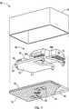
Unter Bezugnahme auf
In der dargestellten Ausführungsform ist die Sammeloptik
Die Reflektoroptik
Die Lichtsteuerbereiche
Das von den Lichtsteuerbereichen
Das das erste optische Element
Alternativ kann das zweite optische Element
Unter Bezugnahme auf die
In der dargestellten Ausführungsform kann das zweite optische Element
Modifikationen der Erfindung sind für Fachleute auf diesem Gebiet und für Erfinder oder Anwender der Erfindung offensichtlich. Daher muss verstanden werden, dass die in den Zeichnungen dargestellten und vorstehend beschriebenen Ausführungsformen lediglich veranschaulichenden Zwecken dienen und nicht den Umfang der Erfindung begrenzen sollen, der durch die Ansprüche festgelegt ist, wie sie gemäß den Prinzipien des Patentgesetzes einschließlich der Äquivalenzlehre interpretiert werden.Modifications of the invention will be apparent to those skilled in the art and to the inventors or practitioners of the invention. Therefore, it should be understood that the embodiments illustrated in the drawings and described above are for illustrative purposes only and are not intended to limit the scope of the invention, which is defined by the claims as interpreted in accordance with the principles of patent law including equivalence.
ZITATE ENTHALTEN IN DER BESCHREIBUNG QUOTES INCLUDE IN THE DESCRIPTION
Diese Liste der vom Anmelder aufgeführten Dokumente wurde automatisiert erzeugt und ist ausschließlich zur besseren Information des Lesers aufgenommen. Die Liste ist nicht Bestandteil der deutschen Patent- bzw. Gebrauchsmusteranmeldung. Das DPMA übernimmt keinerlei Haftung für etwaige Fehler oder Auslassungen.This list of the documents listed by the applicant has been generated automatically and is included solely for the better information of the reader. The list is not part of the German patent or utility model application. The DPMA assumes no liability for any errors or omissions.
Zitierte PatentliteraturCited patent literature
- US 6870656[0018]US 6870656[0018]
- US 6313457[0018]US 6313457[0018]
- US 6359274[0018]US 6359274[0018]
- US 6504142[0018]US 6504142[0018]
- US 6402328[0018]US 6402328[0018]
- US 6379013[0018]US 6379013[0018]
- US 6679608[0018]US 6679608[0018]
- US 6831268[0018]US 6831268[0018]
- US 7543946[0018]US 7543946[0018]
- US 6742904[0018]US Pat. No. 6,742,904[0018]
Claims (20)
Translated fromGermanApplications Claiming Priority (3)
| Application Number | Priority Date | Filing Date | Title |
|---|---|---|---|
| US201261746147P | 2012-12-27 | 2012-12-27 | |
| US61/746,147 | 2012-12-27 | ||
| PCT/US2013/077997WO2014106057A1 (en) | 2012-12-27 | 2013-12-27 | Light system |
Publications (1)
| Publication Number | Publication Date |
|---|---|
| DE212013000261U1true DE212013000261U1 (en) | 2015-08-07 |
Family
ID=51017010
Family Applications (1)
| Application Number | Title | Priority Date | Filing Date |
|---|---|---|---|
| DE212013000261.0UExpired - LifetimeDE212013000261U1 (en) | 2012-12-27 | 2013-12-27 | lighting system |
Country Status (7)
| Country | Link |
|---|---|
| US (2) | US9028119B2 (en) |
| EP (1) | EP2938520B1 (en) |
| JP (1) | JP3203383U (en) |
| KR (1) | KR200482441Y1 (en) |
| CN (1) | CN104903150B (en) |
| DE (1) | DE212013000261U1 (en) |
| WO (1) | WO2014106057A1 (en) |
Cited By (1)
| Publication number | Priority date | Publication date | Assignee | Title |
|---|---|---|---|---|
| DE102017123830A1 (en)* | 2017-10-13 | 2019-04-18 | Dr. Ing. H.C. F. Porsche Aktiengesellschaft | Lighting arrangement for an exterior mirror |
Families Citing this family (17)
| Publication number | Priority date | Publication date | Assignee | Title |
|---|---|---|---|---|
| EP2996101B1 (en)* | 2014-09-12 | 2019-06-26 | Continental Automotive GmbH | Driver assistance system, method for assisting a driver during a parking manoeuvre and program product |
| US10033911B2 (en) | 2015-06-26 | 2018-07-24 | Cognex Corporation | Illumination assembly |
| DE102015114773B4 (en) | 2015-09-03 | 2023-08-10 | SMR Patents S.à.r.l. | Rear-view mirrors with display devices for vehicles |
| US10215359B2 (en)* | 2016-01-29 | 2019-02-26 | Gentex Corporation | Indicator optic for vehicle lighting module |
| DE102016201882A1 (en)* | 2016-02-09 | 2017-08-10 | Bayerische Motoren Werke Aktiengesellschaft | Light module of a vehicle |
| US10106076B2 (en)* | 2016-02-15 | 2018-10-23 | Ford Global Technologies Llc | Three mode police mirror |
| CN107627952B (en)* | 2016-07-18 | 2020-09-18 | 深圳比亚迪微电子有限公司 | Gear shifting light-emitting panel and automobile with same |
| KR101804311B1 (en)* | 2017-03-23 | 2017-12-04 | (주)미경테크 | Back light unit |
| WO2018237002A1 (en)* | 2017-06-21 | 2018-12-27 | Gentex Corporation | Lighting system |
| IT201700071467A1 (en)* | 2017-06-27 | 2018-12-27 | Olsa Spa | OPTICAL SYSTEM WITH OPTICAL ELEMENTS FOR HEADLIGHTS WITH HOMOGENEOUS FUNCTIONS. |
| JP7017394B2 (en)* | 2017-12-14 | 2022-02-08 | 株式会社小糸製作所 | Light guide device |
| US10632907B2 (en)* | 2018-09-10 | 2020-04-28 | Ford Global Technologies Llc | Vehicle lamp assembly for the passenger compartment having a first and second optic for functional lighting |
| EP4094989A4 (en) | 2020-01-23 | 2023-06-14 | LG Innotek Co., Ltd. | Optical assembly and rearview mirror assembly comprising same |
| US11994272B2 (en) | 2021-08-20 | 2024-05-28 | Gentex Corporation | Lighting assembly and illumination system having a lighting assembly |
| US11698180B2 (en)* | 2021-08-23 | 2023-07-11 | Ford Global Technologies, Llc | Vehicle exterior lighting systems with revealable fascia lamp assemblies |
| EP4389524A1 (en)* | 2022-12-22 | 2024-06-26 | Ficomirrors, S.A. | Blind spot indicator assembly for a motor vehicle and rear-view mirror comprising said blind spot indicator assembly |
| KR20240102652A (en) | 2022-12-26 | 2024-07-03 | 현대모비스 주식회사 | Lamp |
Citations (8)
| Publication number | Priority date | Publication date | Assignee | Title |
|---|---|---|---|---|
| US6313457B1 (en) | 1999-01-25 | 2001-11-06 | Gentex Corporation | Moisture detecting system using semiconductor light sensor with integral charge collection |
| US6359274B1 (en) | 1999-01-25 | 2002-03-19 | Gentex Corporation | Photodiode light sensor |
| US6379013B1 (en) | 1999-01-25 | 2002-04-30 | Gentex Corporation | Vehicle equipment control with semiconductor light sensors |
| US6402328B1 (en) | 1999-01-25 | 2002-06-11 | Gentex Corporation | Automatic dimming mirror using semiconductor light sensor with integral charge collection |
| US6679608B2 (en) | 1999-01-25 | 2004-01-20 | Gentex Corporation | Sensor device having an integral anamorphic lens |
| US6831268B2 (en) | 2002-01-10 | 2004-12-14 | Gentex Corporation | Sensor configuration for substantial spacing from a small aperture |
| US6870656B2 (en) | 1997-04-02 | 2005-03-22 | Gentex Corporation | Electrochromic rearview mirror element incorporating a third surface reflector |
| US7543946B2 (en) | 2002-01-10 | 2009-06-09 | Gentex Corporation | Dimmable rearview assembly having a glare sensor |
Family Cites Families (27)
| Publication number | Priority date | Publication date | Assignee | Title |
|---|---|---|---|---|
| US4791339A (en) | 1987-05-05 | 1988-12-13 | Tektronix, Inc. | Liquid crystal light valve with spatially uniform light transmittance characteristics |
| TW331593B (en) | 1996-05-13 | 1998-05-11 | Konika Co Ltd | Planer light source device and light guide plate |
| US6473554B1 (en) | 1996-12-12 | 2002-10-29 | Teledyne Lighting And Display Products, Inc. | Lighting apparatus having low profile |
| US6124886A (en)* | 1997-08-25 | 2000-09-26 | Donnelly Corporation | Modular rearview mirror assembly |
| US6170956B1 (en) | 1998-10-14 | 2001-01-09 | Gentex Corporation | Rearview mirror with display |
| KR100789138B1 (en)* | 2001-09-05 | 2007-12-27 | 삼성전자주식회사 | Lighting device and reflection type liquid crystal display device using the same |
| JP4262113B2 (en)* | 2004-02-13 | 2009-05-13 | シチズン電子株式会社 | Backlight |
| US7204631B2 (en) | 2004-06-30 | 2007-04-17 | 3M Innovative Properties Company | Phosphor based illumination system having a plurality of light guides and an interference reflector |
| US7255469B2 (en) | 2004-06-30 | 2007-08-14 | 3M Innovative Properties Company | Phosphor based illumination system having a light guide and an interference reflector |
| DE102005042523A1 (en)* | 2005-05-31 | 2006-12-07 | Osram Opto Semiconductors Gmbh | lighting device |
| DE102005031023B3 (en) | 2005-07-02 | 2007-01-18 | Deutsches Zentrum für Luft- und Raumfahrt e.V. | Solar collector field for generating electricity has injection system with injection line connecting outlet of first-row collector to inlet of second-row collector |
| US20080024864A1 (en)* | 2006-07-28 | 2008-01-31 | K.W. Muth Company, Inc. | Signaling assembly |
| US7944371B2 (en)* | 2007-11-05 | 2011-05-17 | Magna Mirrors Of America, Inc. | Exterior mirror with indicator |
| JP4561749B2 (en)* | 2007-01-18 | 2010-10-13 | 市光工業株式会社 | VEHICLE LIGHT, VEHICLE OUTSIDE Mirror DEVICE HAVING VEHICLE LIGHT |
| DE502007004000D1 (en)* | 2007-03-14 | 2010-07-15 | Smr Patents Sarl | Rearview mirror for vehicles, preferably for motor vehicles |
| US8287164B2 (en)* | 2008-09-15 | 2012-10-16 | Gentex Corporation | Outside mirror lighting assembly and method of forming same |
| WO2010124028A2 (en) | 2009-04-21 | 2010-10-28 | Vasylyev Sergiy V | Light collection and illumination systems employing planar waveguide |
| US8111444B2 (en) | 2010-03-24 | 2012-02-07 | Eastman Kodak Company | Total internal reflection light valve |
| US7982823B1 (en) | 2010-06-17 | 2011-07-19 | Sharp Laboratories Of America, Inc. | Area active backlight with steerable backlight |
| US8735791B2 (en) | 2010-07-13 | 2014-05-27 | Svv Technology Innovations, Inc. | Light harvesting system employing microstructures for efficient light trapping |
| CZ306888B6 (en)* | 2010-08-06 | 2017-08-30 | Varroc Lighting Systems, s.r.o. | A light-guide module |
| DE102010045847A1 (en) | 2010-09-17 | 2012-03-22 | Automotive Lighting Reutlingen Gmbh | Refelxionsmodul a motor vehicle headlamp |
| JP5944398B2 (en) | 2010-10-28 | 2016-07-05 | バニヤン エナジー インコーポレイテッド | Turning optics for heat collection and lighting systems |
| JP5657358B2 (en)* | 2010-12-02 | 2015-01-21 | スタンレー電気株式会社 | Vehicle lighting |
| US20130094215A1 (en) | 2011-04-04 | 2013-04-18 | Robe Lighting S.R.O. | Light collection system for a luminaire |
| JP2012243493A (en)* | 2011-05-18 | 2012-12-10 | Stanley Electric Co Ltd | Vehicular signal lamp |
| KR101637331B1 (en)* | 2011-11-23 | 2016-07-07 | 무스 미러 시스템즈, 엘엘씨 | Optic assembly having virtual external common focus |
- 2013
- 2013-12-27KRKR2020157000023Upatent/KR200482441Y1/ennot_activeExpired - Lifetime
- 2013-12-27DEDE212013000261.0Upatent/DE212013000261U1/ennot_activeExpired - Lifetime
- 2013-12-27USUS14/142,011patent/US9028119B2/enactiveActive
- 2013-12-27EPEP13867119.3Apatent/EP2938520B1/enactiveActive
- 2013-12-27WOPCT/US2013/077997patent/WO2014106057A1/enactiveApplication Filing
- 2013-12-27JPJP2015600119Upatent/JP3203383U/ennot_activeExpired - Lifetime
- 2013-12-27CNCN201380067818.9Apatent/CN104903150B/enactiveActive
- 2015
- 2015-05-07USUS14/706,109patent/US9403478B2/enactiveActive
Patent Citations (10)
| Publication number | Priority date | Publication date | Assignee | Title |
|---|---|---|---|---|
| US6870656B2 (en) | 1997-04-02 | 2005-03-22 | Gentex Corporation | Electrochromic rearview mirror element incorporating a third surface reflector |
| US6313457B1 (en) | 1999-01-25 | 2001-11-06 | Gentex Corporation | Moisture detecting system using semiconductor light sensor with integral charge collection |
| US6359274B1 (en) | 1999-01-25 | 2002-03-19 | Gentex Corporation | Photodiode light sensor |
| US6379013B1 (en) | 1999-01-25 | 2002-04-30 | Gentex Corporation | Vehicle equipment control with semiconductor light sensors |
| US6402328B1 (en) | 1999-01-25 | 2002-06-11 | Gentex Corporation | Automatic dimming mirror using semiconductor light sensor with integral charge collection |
| US6504142B2 (en) | 1999-01-25 | 2003-01-07 | Gentex Corporation | Photodiode light sensor |
| US6679608B2 (en) | 1999-01-25 | 2004-01-20 | Gentex Corporation | Sensor device having an integral anamorphic lens |
| US6742904B2 (en) | 1999-01-25 | 2004-06-01 | Gentex Corporation | Vehicle equipment control with semiconductor light sensors |
| US6831268B2 (en) | 2002-01-10 | 2004-12-14 | Gentex Corporation | Sensor configuration for substantial spacing from a small aperture |
| US7543946B2 (en) | 2002-01-10 | 2009-06-09 | Gentex Corporation | Dimmable rearview assembly having a glare sensor |
Cited By (1)
| Publication number | Priority date | Publication date | Assignee | Title |
|---|---|---|---|---|
| DE102017123830A1 (en)* | 2017-10-13 | 2019-04-18 | Dr. Ing. H.C. F. Porsche Aktiengesellschaft | Lighting arrangement for an exterior mirror |
Also Published As
| Publication number | Publication date |
|---|---|
| US9028119B2 (en) | 2015-05-12 |
| KR20150003327U (en) | 2015-09-04 |
| EP2938520A1 (en) | 2015-11-04 |
| CN104903150A (en) | 2015-09-09 |
| JP3203383U (en) | 2016-03-31 |
| CN104903150B (en) | 2018-08-07 |
| US20150232023A1 (en) | 2015-08-20 |
| WO2014106057A1 (en) | 2014-07-03 |
| KR200482441Y1 (en) | 2017-01-24 |
| US20140185310A1 (en) | 2014-07-03 |
| EP2938520A4 (en) | 2016-01-27 |
| EP2938520B1 (en) | 2020-04-29 |
| US9403478B2 (en) | 2016-08-02 |
Similar Documents
| Publication | Publication Date | Title |
|---|---|---|
| DE212013000261U1 (en) | lighting system | |
| EP2910847B1 (en) | Light module of a motor vehicle headlight and headlight with such a light module | |
| DE102015119833B4 (en) | Battery charge status indicator for an electric vehicle | |
| DE102011089575B3 (en) | Lighting device for a motor vehicle with a stepped light guide | |
| DE202012013353U1 (en) | Low profile optical lighting assembly for use in a vehicle exterior mirror | |
| DE102015224745A1 (en) | Motor vehicle headlight with a base light assembly and a high beam assembly | |
| WO2016087643A1 (en) | Auxiliary stop lamp for vehicles | |
| DE102013205487A1 (en) | Motor vehicle light for dynamic lighting functions | |
| DE102014202294A1 (en) | Lighting device and method for operating a lighting device | |
| DE102012200903A1 (en) | Optical arrangement and method for optically scanning an object plane with a multi-channel imaging system | |
| EP3467374B1 (en) | Vehicle headlamp | |
| EP3077255B1 (en) | Illumination for detecting raindrops on a pane by means of a camera | |
| DE102016123823A1 (en) | SURFACE MODULE AND SURFACE SOURCE APPARATUS FOR A VEHICLE USING THE SAME | |
| DE102015219211A1 (en) | Light module for a vehicle lighting device | |
| WO2018220069A1 (en) | Semiconductor light source | |
| DE102015112296A1 (en) | Optical sensor device for a motor vehicle, motor vehicle and method | |
| DE102009058807A1 (en) | Sensor for checking value documents | |
| DE102014214710A1 (en) | Rain detection device | |
| DE102013210257A1 (en) | Attachment optics for a light source | |
| DE102012110793A1 (en) | Apparatus and method for imaging a sheet material | |
| DE102019123515A1 (en) | Motor vehicle headlights with two projection light modules of different focal lengths and equally wide illuminated light exit lenses | |
| DE102012002334A1 (en) | Lighting device of a motor vehicle | |
| DE102016100437A1 (en) | Device for image control | |
| DE102014204691A1 (en) | Image pickup device, in particular for vehicle measurement | |
| DE102013225156A1 (en) | Illumination for detecting raindrops on a pane by means of a camera |
Legal Events
| Date | Code | Title | Description |
|---|---|---|---|
| R082 | Change of representative | Representative=s name:MUELLER-BORE & PARTNER PATENTANWAELTE PARTG MB, DE | |
| R207 | Utility model specification | ||
| R150 | Utility model maintained after payment of first maintenance fee after three years | ||
| R151 | Utility model maintained after payment of second maintenance fee after six years | ||
| R152 | Utility model maintained after payment of third maintenance fee after eight years | ||
| R071 | Expiry of right |