DE202021100478U1 - profile system - Google Patents
profile systemDownload PDFInfo
- Publication number
- DE202021100478U1 DE202021100478U1DE202021100478.9UDE202021100478UDE202021100478U1DE 202021100478 U1DE202021100478 U1DE 202021100478U1DE 202021100478 UDE202021100478 UDE 202021100478UDE 202021100478 U1DE202021100478 U1DE 202021100478U1
- Authority
- DE
- Germany
- Prior art keywords
- receiving
- section
- profiles
- profile
- dimensions
- Prior art date
- Legal status (The legal status is an assumption and is not a legal conclusion. Google has not performed a legal analysis and makes no representation as to the accuracy of the status listed.)
- Active
Links
- 239000000463materialSubstances0.000claimsdescription10
- 239000004033plasticSubstances0.000claimsdescription6
- 229920003023plasticPolymers0.000claimsdescription6
- 238000002347injectionMethods0.000claimsdescription2
- 239000007924injectionSubstances0.000claimsdescription2
- 238000003780insertionMethods0.000description9
- 230000037431insertionEffects0.000description9
- 229910052782aluminiumInorganic materials0.000description3
- XAGFODPZIPBFFR-UHFFFAOYSA-NaluminiumChemical compound[Al]XAGFODPZIPBFFR-UHFFFAOYSA-N0.000description3
- XECAHXYUAAWDEL-UHFFFAOYSA-Nacrylonitrile butadiene styreneChemical compoundC=CC=C.C=CC#N.C=CC1=CC=CC=C1XECAHXYUAAWDEL-UHFFFAOYSA-N0.000description2
- 229920000122acrylonitrile butadiene styrenePolymers0.000description2
- 239000004676acrylonitrile butadiene styreneSubstances0.000description2
- 238000004519manufacturing processMethods0.000description2
- 239000004417polycarbonateSubstances0.000description2
- 229910001220stainless steelInorganic materials0.000description2
- 239000010935stainless steelSubstances0.000description2
- 229910000831SteelInorganic materials0.000description1
- 239000000853adhesiveSubstances0.000description1
- 230000001070adhesive effectEffects0.000description1
- 230000006835compressionEffects0.000description1
- 238000007906compressionMethods0.000description1
- 238000012986modificationMethods0.000description1
- 230000004048modificationEffects0.000description1
- 239000012994photoredox catalystSubstances0.000description1
- 229920000515polycarbonatePolymers0.000description1
- 238000004080punchingMethods0.000description1
- 239000010959steelSubstances0.000description1
- 239000000758substrateSubstances0.000description1
- 230000007704transitionEffects0.000description1
Images

Classifications
- F—MECHANICAL ENGINEERING; LIGHTING; HEATING; WEAPONS; BLASTING
- F16—ENGINEERING ELEMENTS AND UNITS; GENERAL MEASURES FOR PRODUCING AND MAINTAINING EFFECTIVE FUNCTIONING OF MACHINES OR INSTALLATIONS; THERMAL INSULATION IN GENERAL
- F16B—DEVICES FOR FASTENING OR SECURING CONSTRUCTIONAL ELEMENTS OR MACHINE PARTS TOGETHER, e.g. NAILS, BOLTS, CIRCLIPS, CLAMPS, CLIPS OR WEDGES; JOINTS OR JOINTING
- F16B7/00—Connections of rods or tubes, e.g. of non-circular section, mutually, including resilient connections
- F16B7/04—Clamping or clipping connections
- F16B7/0406—Clamping or clipping connections for rods or tubes being coaxial
- F16B7/0413—Clamping or clipping connections for rods or tubes being coaxial for tubes using the innerside thereof
- F—MECHANICAL ENGINEERING; LIGHTING; HEATING; WEAPONS; BLASTING
- F16—ENGINEERING ELEMENTS AND UNITS; GENERAL MEASURES FOR PRODUCING AND MAINTAINING EFFECTIVE FUNCTIONING OF MACHINES OR INSTALLATIONS; THERMAL INSULATION IN GENERAL
- F16B—DEVICES FOR FASTENING OR SECURING CONSTRUCTIONAL ELEMENTS OR MACHINE PARTS TOGETHER, e.g. NAILS, BOLTS, CIRCLIPS, CLAMPS, CLIPS OR WEDGES; JOINTS OR JOINTING
- F16B2/00—Friction-grip releasable fastenings
- F16B2/02—Clamps, i.e. with gripping action effected by positive means other than the inherent resistance to deformation of the material of the fastening
- F16B2/04—Clamps, i.e. with gripping action effected by positive means other than the inherent resistance to deformation of the material of the fastening internal, i.e. with spreading action
- A—HUMAN NECESSITIES
- A47—FURNITURE; DOMESTIC ARTICLES OR APPLIANCES; COFFEE MILLS; SPICE MILLS; SUCTION CLEANERS IN GENERAL
- A47B—TABLES; DESKS; OFFICE FURNITURE; CABINETS; DRAWERS; GENERAL DETAILS OF FURNITURE
- A47B47/00—Cabinets, racks or shelf units, characterised by features related to dismountability or building-up from elements
- A47B47/0016—Node corner connectors, e.g. cubic
- F—MECHANICAL ENGINEERING; LIGHTING; HEATING; WEAPONS; BLASTING
- F16—ENGINEERING ELEMENTS AND UNITS; GENERAL MEASURES FOR PRODUCING AND MAINTAINING EFFECTIVE FUNCTIONING OF MACHINES OR INSTALLATIONS; THERMAL INSULATION IN GENERAL
- F16B—DEVICES FOR FASTENING OR SECURING CONSTRUCTIONAL ELEMENTS OR MACHINE PARTS TOGETHER, e.g. NAILS, BOLTS, CIRCLIPS, CLAMPS, CLIPS OR WEDGES; JOINTS OR JOINTING
- F16B12/00—Jointing of furniture or the like, e.g. hidden from exterior
- F16B12/10—Jointing of furniture or the like, e.g. hidden from exterior using pegs, bolts, tenons, clamps, clips, or the like
- F16B12/12—Jointing of furniture or the like, e.g. hidden from exterior using pegs, bolts, tenons, clamps, clips, or the like for non-metal furniture parts, e.g. made of wood, of plastics
- F16B12/24—Jointing of furniture or the like, e.g. hidden from exterior using pegs, bolts, tenons, clamps, clips, or the like for non-metal furniture parts, e.g. made of wood, of plastics using separate pins, dowels, or the like
- F—MECHANICAL ENGINEERING; LIGHTING; HEATING; WEAPONS; BLASTING
- F16—ENGINEERING ELEMENTS AND UNITS; GENERAL MEASURES FOR PRODUCING AND MAINTAINING EFFECTIVE FUNCTIONING OF MACHINES OR INSTALLATIONS; THERMAL INSULATION IN GENERAL
- F16B—DEVICES FOR FASTENING OR SECURING CONSTRUCTIONAL ELEMENTS OR MACHINE PARTS TOGETHER, e.g. NAILS, BOLTS, CIRCLIPS, CLAMPS, CLIPS OR WEDGES; JOINTS OR JOINTING
- F16B13/00—Dowels or other devices fastened in walls or the like by inserting them in holes made therein for that purpose
- F16B13/02—Dowels or other devices fastened in walls or the like by inserting them in holes made therein for that purpose in one piece with protrusions or ridges on the shaft
- F—MECHANICAL ENGINEERING; LIGHTING; HEATING; WEAPONS; BLASTING
- F16—ENGINEERING ELEMENTS AND UNITS; GENERAL MEASURES FOR PRODUCING AND MAINTAINING EFFECTIVE FUNCTIONING OF MACHINES OR INSTALLATIONS; THERMAL INSULATION IN GENERAL
- F16B—DEVICES FOR FASTENING OR SECURING CONSTRUCTIONAL ELEMENTS OR MACHINE PARTS TOGETHER, e.g. NAILS, BOLTS, CIRCLIPS, CLAMPS, CLIPS OR WEDGES; JOINTS OR JOINTING
- F16B19/00—Bolts without screw-thread; Pins, including deformable elements; Rivets
- F16B19/002—Resiliently deformable pins
- F16B19/004—Resiliently deformable pins made in one piece
- F—MECHANICAL ENGINEERING; LIGHTING; HEATING; WEAPONS; BLASTING
- F16—ENGINEERING ELEMENTS AND UNITS; GENERAL MEASURES FOR PRODUCING AND MAINTAINING EFFECTIVE FUNCTIONING OF MACHINES OR INSTALLATIONS; THERMAL INSULATION IN GENERAL
- F16B—DEVICES FOR FASTENING OR SECURING CONSTRUCTIONAL ELEMENTS OR MACHINE PARTS TOGETHER, e.g. NAILS, BOLTS, CIRCLIPS, CLAMPS, CLIPS OR WEDGES; JOINTS OR JOINTING
- F16B19/00—Bolts without screw-thread; Pins, including deformable elements; Rivets
- F16B19/02—Bolts or sleeves for positioning of machine parts, e.g. notched taper pins, fitting pins, sleeves, eccentric positioning rings
- F—MECHANICAL ENGINEERING; LIGHTING; HEATING; WEAPONS; BLASTING
- F16—ENGINEERING ELEMENTS AND UNITS; GENERAL MEASURES FOR PRODUCING AND MAINTAINING EFFECTIVE FUNCTIONING OF MACHINES OR INSTALLATIONS; THERMAL INSULATION IN GENERAL
- F16B—DEVICES FOR FASTENING OR SECURING CONSTRUCTIONAL ELEMENTS OR MACHINE PARTS TOGETHER, e.g. NAILS, BOLTS, CIRCLIPS, CLAMPS, CLIPS OR WEDGES; JOINTS OR JOINTING
- F16B4/00—Shrinkage connections, e.g. assembled with the parts at different temperature; Force fits; Non-releasable friction-grip fastenings
- F16B4/004—Press fits, force fits, interference fits, i.e. fits without heat or chemical treatment
Landscapes
- Engineering & Computer Science (AREA)
- General Engineering & Computer Science (AREA)
- Mechanical Engineering (AREA)
- Connection Of Plates (AREA)
- Mutual Connection Of Rods And Tubes (AREA)
Abstract
Translated fromGerman
Description
Translated fromGermanDie vorliegende Erfindung betrifft ein System umfassend längliche Profile, die über ihre Länge einen konstanten Querschnitt aufweisen, sowie Zwischen- und/oder Abschlusselemente, die dazu ausgelegt sind, zwischen Profilen angeordnet zu werden oder ein Profil stirnseitig abzuschließen.The present invention relates to a system comprising elongate profiles which have a constant cross-section over their length, as well as intermediate and/or terminating elements which are designed to be arranged between profiles or to close off a profile at the front.
Profilsysteme der eingangs genannten Art sind im Stand der Technik in unterschiedlichsten Ausgestaltungen bekannt. Die Zwischen- und/oder Abflusselemente sind normalerweise mit einem oder mehreren auswärts vorstehenden Verbindungsabschnitten ausgeführt, die sich stirnseitig in den Querschnitt eines Profils einsetzen lassen. Die Befestigung eines Zwischen- und/oder Abschlusselementes kann dann beispielsweise unter Verwendung eines Klebstoffs folgen. Auch sind Varianten bekannt, bei denen die Abmessungen der Außenkonturen der Verbindungsabschnitte der Zwischen- und/oder Abschlusselemente derart an die Innenkontur des Querschnitts der Profile angepasst sind, dass sich die Verbindungsabschnitte unter Druckausübung reibschlüssig in die Profile einsetzen lassen. Die zuletzt genannte Variante setzt allerdings geringe Toleranzen voraus, was die Fertigung sowohl der Profile als auch der Zwischen- und/oder Abschlusselemente deutlich erschwert und verteuert.Profile systems of the type mentioned are known in the prior art in a wide variety of configurations. The intermediate and/or drainage elements are normally designed with one or more outwardly protruding connecting sections which can be inserted end-to-end in the cross-section of a profile. An intermediate and/or terminating element can then be attached using an adhesive, for example. Variants are also known in which the dimensions of the outer contours of the connecting sections of the intermediate and/or end elements are adapted to the inner contour of the cross section of the profiles in such a way that the connecting sections can be inserted frictionally into the profiles when pressure is applied. However, the latter variant requires low tolerances, which makes the production of both the profiles and the intermediate and/or end elements significantly more difficult and expensive.
Ausgehend von diesem Stand der Technik ist es eine Aufgabe der vorliegenden Erfindung, ein System der eingangs genannten Art zu schaffen, mit dem sich die Zwischen- und/oder Abschlusselemente sicher und lösbar stirnseitig an den Profilen befestigen lassen.Proceeding from this state of the art, it is an object of the present invention to create a system of the type mentioned at the outset, with which the intermediate and/or end elements can be securely and detachably fastened to the front faces of the profiles.
Zur Lösung dieser Aufgabe schafft die vorliegende Erfindung ein System umfassend längliche Profile, die über ihre Länge einen konstanten Querschnitt aufweisen, Zwischen- und/oder Abschlusselemente, die dazu ausgelegt sind, zwischen Profilen angeordnet zu werden oder ein Profil stirnseitig abzuschließen, und jeweils zwei Endbereiche aufweisende, als separate Bauteile vorgesehene Verbindungsstifte, die dazu ausgelegt sind, ein Profil stirnseitig mit einem Zwischen- und/oder Abschlusselement lösbar zu verbinden, wobei die Profilquerschnitte stirnseitig Aufnahmeöffnungen zur Aufnahme des ersten Endbereiches eines Verbindungsstiftes bilden, wobei die Zwischen- und/oder Abschlusselemente Aufnahmelöcher zur Aufnahme des zweiten Endbereiches eines Verbindungsstiftes aufweisen, wobei sich die Aufnahmelöcher der Zwischen- und/oder Abschlusselemente jeweils durch eine Wand in einen Hohlraum des Zwischen- und/oder Abschlusselements erstrecken, wobei der erste Endbereich der Verbindungsstifte einen radial auswärts gewölbten Klemmabschnitt maximalen Durchmessers aufweist, der mit zumindest einer länglichen, sich in Längsrichtung des Verbindungsstiftes und durch diesen radial hindurch erstreckenden Aussparung versehen ist, wobei die Abmessungen des Klemmabschnitts derart an die Abmessungen der Aufnahmeöffnungen angepasst sind, dass sich der Klemmabschnitt unter Erzeugung eines Form- und Kraftschlusses in eine Aufnahmeöffnung einsetzen lässt, und wobei der zweite Endbereich einen eine ringförmige Vertiefung aufweisenden Aufnahmeabschnitt umfasst, dessen Abmessungen derart an die Abmessungen der Aufnahmelöcher angepasst sind, dass der Aufnahmeabschnitt die ein Aufnahmeloch umgebende Außenwand eines Zwischen- und/oder Abschlusselements zumindest formschlüssig aufnimmt.To solve this problem, the present invention creates a system comprising elongate profiles which have a constant cross-section over their length, intermediate and/or end elements which are designed to be arranged between profiles or to close a profile at the front, and two end regions in each case having connecting pins provided as separate components, which are designed to releasably connect a profile to an intermediate and/or terminating element at the front, the profile cross sections forming receiving openings on the front to receive the first end region of a connecting pin, the intermediate and/or terminating elements Have receiving holes for receiving the second end portion of a connecting pin, wherein the receiving holes of the intermediate and / or end elements each extend through a wall into a cavity of the intermediate and / or end element, wherein the first end portion of the connecting pins a has a radially outwardly curved clamping section of maximum diameter, which is provided with at least one elongate recess extending in the longitudinal direction of the connecting pin and extending radially through it, the dimensions of the clamping section being adapted to the dimensions of the receiving openings in such a way that the clamping section expands, creating a positive and non-positive fit can be inserted into a receiving opening, and wherein the second end region comprises a receiving section having an annular depression, the dimensions of which are adapted to the dimensions of the receiving holes in such a way that the receiving section at least covers the outer wall of an intermediate and/or closing element surrounding a receiving hole form-fitting.
Ein wesentlicher Vorteil des erfindungsgemäßen Systems besteht darin, dass sich die einzelnen Komponenten aufgrund nicht zu kleiner Toleranzbereiche einfach und preiswert fertigen lassen. Die Fixierung eines Verbindungsstiftes an einem Profil erfolgt über den radial auswärts gewölbten Klemmabschnitt des ersten Endbereiches eines Verbindungsstiftes, dessen Außendurchmesser beim Einführen in eine Aufnahmeöffnung des Profils komprimiert wird, wodurch zeitgleich eine form- und kraftschlüssige Verbindung erzeugt wird. Die zur Stauchung des Außendurchmessers des Klemmabschnittes erforderlicher Elastizität wird durch die Aussparung des Klemmabschnitts bereitgestellt. Die Verbindung eines Verbindungsstiftes mit einem Zwischen- und/oder Abschlusselement erfolgt über den Aufnahmeabschnitt des zweiten Endbereiches des Verbindungsstiftes, der mit der ringförmigen Vertiefung versehen ist. Wird das freie Ende des zweiten Endbereiches in ein Aufnahmeloch eines Zwischen- und/oder Abschlusselementes mit Druck eingeführt, so wird eine zumindest formschlüssige Verbindung erzielt, sobald die das entsprechende Aufnahmeloch umgebende Außenwand des Zwischen- und/oder Abschlusselementes in die ringförmige Vertiefung des Aufnahmeabschnitts einschnappt oder einrastet. Insgesamt lassen sich die Komponenten des erfindungsgemäßen Systems schnell und einfach montieren, wodurch eine sehr gute Handhabbarkeit erzielt wird. Dabei wird eine sehr verlässliche und dennoch lösbare Verbindung zwischen den einzelnen Komponenten bereitgestellt.An essential advantage of the system according to the invention is that the individual components can be manufactured simply and inexpensively because the tolerance ranges are not too small. A connecting pin is fixed to a profile via the radially outwardly curved clamping section of the first end area of a connecting pin, the outer diameter of which is compressed when it is inserted into a receiving opening in the profile, thereby creating a positive and non-positive connection at the same time. The elasticity required for compressing the outer diameter of the clamping section is provided by the recess in the clamping section. A connecting pin is connected to an intermediate and/or terminating element via the receiving section of the second end region of the connecting pin, which is provided with the annular recess. If the free end of the second end region is inserted with pressure into a receiving hole of an intermediate and/or terminating element, an at least form-fitting connection is achieved as soon as the outer wall of the intermediate and/or terminating element surrounding the corresponding receiving hole snaps into the annular recess of the receiving section or snaps. All in all, the components of the system according to the invention can be installed quickly and easily, as a result of which very good handling is achieved. A very reliable and yet detachable connection is provided between the individual components.
Bevorzugt verjüngt sich der Durchmesser des ersten Endbereiches der Verbindungsstifte ausgehend von dem Klemmabschnitt zum freien Ende hin, wodurch ein insbesondere konusförmiger Einführabschnitt erzeugt wird, der das Einsetzen des freien Endes des ersten Endbereiches in eine Aufnahmeöffnung eines Profils deutlich erleichtert.The diameter of the first end area of the connecting pins preferably tapers from the clamping section to the free end, thereby creating a particularly conical insertion section that significantly facilitates the insertion of the free end of the first end area into a receiving opening of a profile.
Der erste Endbereich der Verbindungsstifte weist vorteilhaft einen benachbart zum Klemmabschnitt angeordneten, zum zweiten Endbereich weisenden Stützabschnitt auf, der mit in Umfangsrichtung beabstandet zueinander angeordneten, radial auswärts vorstehenden Stützvorsprüngen versehen ist. Die Abmessungen der Stützvorsprünge sind vorteilhaft derart gewählt, dass sie sich beim Einsetzen des ersten Endbereiches in eine entsprechende Aufnahmeöffnung eines Profils an das Profil anlegen, um auch hier einen Formschluss zu erzielen. Der Außendurchmesser des ersten Endbereiches im Bereich der Stützvorsprünge entspricht vorteilhaft dem Durchmesser der Aufnahmeöffnungen oder ist geringfügig größer. Letztere Variante ist insbesondere dann zu bevorzugen, wenn das Material der Verbindungsstifte deutlich weicher oder deutlich härter als das Material der Profile ist, so dass die Stützvorsprünge entweder materialbedingt gestaucht werden oder sich in das Material der Profile eindrücken. Die Stützvorsprünge sind insbesondere länglich ausgebildet und erstrecken sich in Längsrichtung des Verbindungsstiftes.Advantageously, the first end region of the connecting pins has a terminal adjacent to the clamping tab Section arranged, to the second end pointing support portion which is spaced apart from each other in the circumferential direction, radially outwardly projecting support projections is provided. The dimensions of the supporting projections are advantageously selected in such a way that when the first end region is inserted into a corresponding receiving opening of a profile, they rest against the profile in order to achieve a positive fit here as well. The outer diameter of the first end area in the area of the supporting projections advantageously corresponds to the diameter of the receiving openings or is slightly larger. The latter variant is to be preferred in particular when the material of the connecting pins is significantly softer or significantly harder than the material of the profiles, so that the supporting projections are either compressed due to the material or are pressed into the material of the profiles. The supporting projections are in particular elongate and extend in the longitudinal direction of the connecting pin.
Gemäß einer Ausgestaltung der vorliegenden Erfindung ist der Stützabschnitt des ersten Endbereiches unmittelbar benachbart zum Aufnahmeabschnitt des zweiten Endbereiches angeordnet.According to one embodiment of the present invention, the support section of the first end area is arranged directly adjacent to the receiving section of the second end area.
Vorteilhaft verjüngt sich der Durchmesser des zweiten Endbereiches der Verbindungsstifte ausgehend vom Aufnahmeabschnitt zum freien Ende, so dass auch am Ende des zweiten Endbereiches ein insbesondere konusförmiger Einführabschnitt vorhanden ist, der das Einführen des zweiten Endbereiches in ein Aufnahmeloch eines Zwischen- und/oder Abflusselementes erleichtert.Advantageously, the diameter of the second end area of the connecting pins tapers, starting from the receiving section towards the free end, so that there is also an in particular conical insertion section at the end of the second end area, which facilitates the insertion of the second end area into a receiving hole of an intermediate and/or drainage element.
Gemäß einer Ausgestaltung der vorliegenden Erfindung ist der zweite Endbereich der Verbindungsstifte mit einer sich ausgehend vom freien Ende des zweiten Endbereiches in Längsrichtung des Verbindungsstiftes und radial durch diesen hindurch erstreckenden Nut versehen. Eine derart ausgebildete Nut ermöglicht eine Stauchung des Außendurchmessers des zweiten Endbereiches beim Einführen in ein entsprechendes Aufnahmeloch eines Zwischen- und/oder Abschlusselementes, was das Herstellen der zuvor beschriebene Rastverbindung vereinfacht.According to one embodiment of the present invention, the second end area of the connecting pins is provided with a groove that extends from the free end of the second end area in the longitudinal direction of the connecting pin and radially through it. A groove designed in this way enables the outer diameter of the second end region to be compressed when it is inserted into a corresponding receiving hole of an intermediate and/or terminating element, which simplifies the production of the latching connection described above.
Vorteilhaft erstreckt sich die Nut durch den gesamten zweiten Endbereich der Verbindungsstifte, wodurch eine sehr gute Flexibilität sichergestellt ist.The groove advantageously extends through the entire second end area of the connecting pins, as a result of which very good flexibility is ensured.
Bevorzugt sind die Verbindungsstifte aus Kunststoff hergestellt, beispielsweise aus ABS bzw. Acrylnitril-Butadien-Styrol, aus PC bzw. Polycarbonat oder dergleichen.The connecting pins are preferably made of plastic, for example ABS or acrylonitrile butadiene styrene, PC or polycarbonate or the like.
Insbesondere sind die Verbindungsstifte als Spritzgussteile hergestellt.In particular, the connecting pins are manufactured as injection molded parts.
Die Abmessungen der Sichtflächen der Profile und die Abmessungen der Sichtflächen der Zwischen- und/oder Abschlusselemente sind bevorzugt derart aufeinander abgestimmt, dass diese in miteinander verbundenem Zustand bündig ineinander übergehen, wodurch ein optisch ansprechendes Erscheinungsbild erzielt wird.The dimensions of the visible surfaces of the profiles and the dimensions of the visible surfaces of the intermediate and/or end elements are preferably matched to one another in such a way that they merge flush into one another when they are connected, thereby achieving a visually appealing appearance.
Die Profilquerschnitte sind stirnseitig vorteilhaft jeweils mit zwei Aufnahmeöffnungen und die Zwischen- und/oder Abschlusselemente an zumindest einer Wand jeweils mit zwei entsprechend positionierten Aufnahmelöchern versehen. Dies führt dazu, dass ein Profil mit einem Zwischen- und/oder Abschlusselement unter Verwendung von zwei Verbindungsstiften verbunden werden kann, wodurch eine Verdrehsicherung bereitgestellt wird. Somit ist stets eine ordnungsgemäße relative Positionierung der Bauteile gewährleistet.The profile cross-sections are advantageously each provided with two receiving openings on the face side and the intermediate and/or end elements on at least one wall are each provided with two correspondingly positioned receiving holes. This means that a profile can be connected to an intermediate and/or terminating element using two connecting pins, which provides an anti-twist protection. This ensures that the components are always correctly positioned relative to one another.
Vorteilhaft sind die Profile und die Zwischen- und/oder Abschlusselemente aus dem gleichen Material hergestellt, was zu einem einheitlichen Erscheinungsbild führt.The profiles and the intermediate and/or end elements are advantageously made of the same material, which leads to a uniform appearance.
Insbesondere handelt es sich bei den Profilen um Fliesenabschlussprofile, um Leuchtmittel aufnehmende Profile oder um Kabelkanalprofile. Mit Leuchtmittel aufnehmenden Profilen sind insbesondere solche Profile gemeint, an denen LED-Streifen und gegebenenfalls Streuscheiben befestigt sind.In particular, the profiles are tile end profiles, profiles accommodating lamps or cable duct profiles. Profiles accommodating lamps mean, in particular, those profiles to which LED strips and possibly diffusers are attached.
Weitere Merkmale und Vorteile der vorliegenden Erfindung werden anhand der nachfolgenden Beschreibung von Systemen gemäß Ausführungsformen der vorliegenden Erfindung unter Bezugnahme auf die beiliegende Zeichnung deutlich. Darin ist
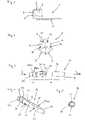
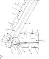
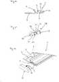
1 eine Stirnseitenansicht eines Profils gemäß einer ersten Ausführungsform der vorliegenden Erfindung;2 eine perspektivische Ansicht eines Zwischenelementes gemäß einer Ausführungsform der vorliegenden Erfindung;3 eine Seitenansicht des eines Verbindungsstiftes gemäß einer Ausführungsform der vorliegenden Erfindung4 eine perspektivische Ansicht des in3 dargestellten Verbindungsstiftes;5 eine Stirnseitenansicht des Verbindungsstiftes in Richtung des Pfeils V in4 ;6 eine perspektivische Explosionsansicht der in den1 bis5 dargestellten Komponenten während ihrer der Montage;7 eine Stirnseitenansicht eines Profils gemäß einer zweiten Ausführungsform der vorliegenden Erfindung;8 eine perspektivische Explosions-Rückansicht der in den3 bis5 sowie 7 dargestellten Komponenten während der Montage unter Verwendung eines Zwischenelementes gemäß einer zweiten Ausführungsform der vorliegenden Erfindung;9 eine perspektivische Explosions-Vorderansicht der in8 dargestellten Anordnung;10 eine Stirnseitenansicht eines Profils gemäß einer dritten Ausführungsform der vorliegenden Erfindung;11 eine perspektivische Ansicht eines Abschlusselementes gemäß einer Ausführungsform der vorliegenden Erfindung; und12 eine perspektivische Explosionsansicht der in den3 bis5 sowie 10 und 11 dargestellten Komponenten während der Montage.
1 an end view of a profile according to a first embodiment of the present invention;2 a perspective view of an intermediate element according to an embodiment of the present invention;3 12 is a side view of a connector pin according to an embodiment of the present invention4 a perspective view of the in3 illustrated connecting pin;5 an end view of the connecting pin in the direction of arrow V in4 ;6 an exploded perspective view of the in the1 until5 components shown during assembly;7 an end view of a profile according to a second embodiment of the present invention;8th Fig. 12 is an exploded rear perspective view of the one shown in Figs3 until5 7 and 7 during assembly using an intermediate member according to a second embodiment of the present invention;9 an exploded front perspective view of FIG8th arrangement shown;10 an end view of a profile according to a third embodiment of the present invention;11 a perspective view of a closing element according to an embodiment of the present invention; and12 an exploded perspective view of the in the3 until5 and 10 and 11 during assembly.
Gleiche Bezugsziffern betreffend nachfolgend gleiche oder gleichartig ausgebildete Bauteile oder Bauteilbereiche.The same reference numerals below relate to the same or similarly designed components or component areas.
Die
Zur Montage der in den
Es sollte klar sein, dass die zuvor beschriebenen Ausführungsformen lediglich als Beispiel dienen. Entsprechend sind Modifikationen und Änderungen der darin gezeigten Komponenten möglich, ohne den durch die beiliegenden Ansprüche definierten Schutzbereich zu verlassen.It should be understood that the embodiments described above are given by way of example only to. Accordingly, modifications and changes can be made to the components shown herein without departing from the scope of protection as defined by the appended claims.
BezugszeichenlisteReference List
- 11
- Profilprofile
- 22
- Ausstanzungpunching
- 33
- Befestigungsabschnittattachment section
- 44
- Anlageabschnittinvestment section
- 55
- Aufnahmeöffnungintake opening
- 66
- Sichtflächeface
- 88th
- Zwischenelementintermediate element
- 99
- Sichtflächeface
- 1111
- Außenwandouter wall
- 1212
- Außenwandouter wall
- 1313
- Aufnahmelochreceiving hole
- 1414
- Verbindungsstiftconnecting pin
- 1515
- erster Endbereichfirst end area
- 1616
- zweiter Endbereichsecond end area
- 1717
- Klemmabschnittclamping section
- 1818
- Aussparungrecess
- 1919
- Einführabschnittinsertion section
- 2020
- Stützabschnittsupport section
- 2121
- Stützvorsprungsupport projection
- 2222
- Vertiefungdeepening
- 2323
- Aufnahmeabschnittrecording section
- 2424
- Einführabschnittinsertion section
- 2525
- Nutgroove
- 2626
- Montageabschnittassembly section
- 2727
- Aufnahmenutreceiving groove
- 2828
- Abschlusselementfinal element
- 2929
- Stirnwandbulkhead
- 3030
- SeitenwandSide wall
- 3131
- SeitenwandSide wall
- 3232
- Vorsprunghead Start
Claims (13)
Translated fromGermanPriority Applications (6)
| Application Number | Priority Date | Filing Date | Title |
|---|---|---|---|
| DE202021100478.9UDE202021100478U1 (en) | 2021-02-01 | 2021-02-01 | profile system |
| US17/319,588US12180987B2 (en) | 2021-02-01 | 2021-05-13 | Profile system for intersecting joints |
| CA3119937ACA3119937A1 (en) | 2021-02-01 | 2021-05-27 | Profile system for intersecting joints |
| MX2021007036AMX2021007036A (en) | 2021-02-01 | 2021-06-11 | PROFILE SYSTEM FOR INTERSECTING JOINTS. |
| EP21210442.6AEP4036424A1 (en) | 2021-02-01 | 2021-11-25 | Profile system |
| US18/778,026US20250052264A1 (en) | 2021-02-01 | 2024-07-19 | Profile System for Intersecting Joints |
Applications Claiming Priority (1)
| Application Number | Priority Date | Filing Date | Title |
|---|---|---|---|
| DE202021100478.9UDE202021100478U1 (en) | 2021-02-01 | 2021-02-01 | profile system |
Publications (1)
| Publication Number | Publication Date |
|---|---|
| DE202021100478U1true DE202021100478U1 (en) | 2022-05-03 |
Family
ID=78829355
Family Applications (1)
| Application Number | Title | Priority Date | Filing Date |
|---|---|---|---|
| DE202021100478.9UActiveDE202021100478U1 (en) | 2021-02-01 | 2021-02-01 | profile system |
Country Status (5)
| Country | Link |
|---|---|
| US (2) | US12180987B2 (en) |
| EP (1) | EP4036424A1 (en) |
| CA (1) | CA3119937A1 (en) |
| DE (1) | DE202021100478U1 (en) |
| MX (1) | MX2021007036A (en) |
Families Citing this family (1)
| Publication number | Priority date | Publication date | Assignee | Title |
|---|---|---|---|---|
| CN118475790A (en)* | 2021-12-13 | 2024-08-09 | 昕诺飞控股有限公司 | Tile lamp fixture for a suspended tile lamp ceiling assembly and the suspended tile lamp ceiling assembly |
Citations (4)
| Publication number | Priority date | Publication date | Assignee | Title |
|---|---|---|---|---|
| DE9200696U1 (en) | 1992-01-22 | 1992-04-16 | Huwil-Werke GmbH Möbelschloß- und Beschlagfabriken, 5207 Ruppichteroth | Connecting part, especially corner connector for hollow profiles |
| DE202011110083U1 (en) | 2011-05-07 | 2013-01-07 | Josef Stengel | pipe connectors |
| DE102014114909A1 (en) | 2014-10-14 | 2016-04-14 | Flymax Gmbh | profile connector |
| DE202020005046U1 (en) | 2019-12-04 | 2021-04-09 | Matrix-Systems GmbH | Connection device for forming box profiles, in particular for exhibition and shop fitting systems |
Family Cites Families (137)
| Publication number | Priority date | Publication date | Assignee | Title |
|---|---|---|---|---|
| GB191417164A (en) | 1914-07-20 | 1914-12-31 | British Murac Syndicate Ltd | Improvements in or relating to Roads and Ways. |
| US2230688A (en) | 1939-03-09 | 1941-02-04 | Goodrich Co B F | Expansion joint |
| US2843889A (en) | 1955-11-04 | 1958-07-22 | Robert R Keller | Decorative molding strips and the like |
| US3213584A (en) | 1963-07-31 | 1965-10-26 | Standard Products Co | Gaskets |
| US3396640A (en) | 1966-04-25 | 1968-08-13 | Grace W R & Co | Joint sealing devices |
| LU54653A1 (en) | 1967-10-11 | 1969-07-03 | ||
| US3598026A (en) | 1969-01-31 | 1971-08-10 | Grace W R & Co | Joint-sealing apparatus |
| US3704564A (en) | 1969-12-29 | 1972-12-05 | Hakko Co | Method of fabricating structural block assemblies |
| US3646716A (en) | 1970-02-11 | 1972-03-07 | Myron Jenner | Weather seal for building structures |
| DE7008903U (en) | 1970-03-11 | 1970-09-10 | Staff & Schwarz Gmbh | TRIPOD, IN PARTICULAR FOR LIGHTS. |
| US3682053A (en) | 1971-02-16 | 1972-08-08 | Acme Highway Prod | Sealing member |
| DE2114956C3 (en) | 1971-03-27 | 1979-04-12 | Migua-Mitteldeutsche Gummi- Und Asbest-Gesellschaft Hammerschmidt & Co, 5628 Heiligenhaus | Device for bridging an expansion joint |
| US3827204A (en) | 1972-03-14 | 1974-08-06 | Thiokol Chemical Corp | Sealed joint for sectionalized flooring and method of making the same |
| US3838931A (en) | 1972-05-29 | 1974-10-01 | A Valla | Elastic road bridge joint |
| US3974614A (en) | 1972-07-27 | 1976-08-17 | Strong Gardner H | Expansion-contraction joint |
| US3868802A (en) | 1972-10-11 | 1975-03-04 | Rohr Industries Inc | Flush joint structure for adjoining panels |
| FR2262217A1 (en)* | 1974-02-22 | 1975-09-19 | Guillaumond Gabriel | Joining blocks used for cabinets or shelving - adapt to different methods of fixing |
| JPS5420187Y2 (en) | 1974-11-26 | 1979-07-23 | ||
| DE7801755U1 (en) | 1978-01-21 | 1978-05-11 | Poggi, Leo, Mailand (Italien) | EXPANSION JOINT FOR CONNECTION LINES OF LARGE SURFACES IN BUILDINGS |
| DE2838664A1 (en)* | 1978-09-05 | 1980-05-22 | Bernd Simon | Unit system furniture construction - consists of hollow sections joined by dowels to form joined connections |
| US4360992A (en) | 1978-11-22 | 1982-11-30 | Marino Vincent J | Dimensionally stable wood flooring |
| US4346542A (en) | 1979-07-09 | 1982-08-31 | Kohkichi Tateno | Joint for use in concrete deposit |
| DE3020035C2 (en) | 1980-05-24 | 1985-01-10 | Migua Hammerschmidt GmbH, 5628 Heiligenhaus | Movement joint sealing device |
| US4454699A (en)* | 1982-03-15 | 1984-06-19 | Fred Strobl | Brick fastening device |
| CA1191304A (en) | 1983-02-23 | 1985-08-06 | Richard A. Morrison | Mat module with ramp strip |
| US4484407A (en)* | 1983-03-28 | 1984-11-27 | Brio Toy Ab | Connection element for assembling toys |
| DE3405571A1 (en)* | 1983-08-30 | 1985-08-22 | Fritz Osterloh GmbH u. Co KG, 7015 Korntal-Münchingen | Set of structural elements for assembling furniture |
| DE3401032A1 (en) | 1984-01-13 | 1985-07-18 | Artur Dr.H.C. 7244 Waldachtal Fischer | SPREADING NAIL |
| NL8400519A (en)* | 1984-02-17 | 1985-09-16 | Keen Egbert | APPARATUS WITH FRAME COMPOSITE AND CONNECTORS AND CONNECTOR THEREFOR. |
| DE3407075C2 (en) | 1984-02-27 | 1986-09-18 | Alfred 8068 Pfaffenhofen Hartkorn | Joint bridging construction for subsequent installation in buildings or components that are spaced apart |
| DE3407995C2 (en) | 1984-03-03 | 1994-08-11 | Irbit Research & Consulting Ag | Foam sealing tape and its use |
| DE3429860A1 (en) | 1984-08-14 | 1986-03-13 | Glacier GmbH - Sollinger Hütte, 3418 Uslar | Rubber profile |
| US4610561A (en)* | 1984-12-31 | 1986-09-09 | Italtel Tecnomeccanica S.P.A. | Sectional structure for carpentry, particularly to realize cubicles |
| DE3503394A1 (en) | 1985-02-01 | 1986-08-14 | Werner 5860 Iserlohn Schlüter | DEVICE FOR FORMING EXPANSION JOINTS IN FLOORS OR WALLS WITH RIGID COVERINGS, ESPECIALLY WITH CERAMIC PANELS |
| US4651488A (en) | 1986-02-03 | 1987-03-24 | Nicholas John D | Expansion joint for plaster walls |
| US4861043A (en) | 1986-03-31 | 1989-08-29 | Bechtel International Corporation | Pressure/compression concrete joint seal |
| US4793162A (en) | 1986-08-07 | 1988-12-27 | Spt, Inc. | Method for repairing failed waterstops and products relating to same |
| CH677693A5 (en)* | 1988-05-24 | 1991-06-14 | Gehri Innenausbau Ag | |
| FR2634259B1 (en)* | 1988-07-13 | 1990-11-09 | Girinon Rene | ASSEMBLY SYSTEM FOR PRODUCING VARIOUS OBJECTS OF THE FURNITURE TYPE IN PARTICULAR |
| US5121579A (en) | 1988-08-05 | 1992-06-16 | Portage Holding, Inc. | Portable sectional flooring system with post support |
| AU610398B2 (en) | 1989-05-10 | 1991-05-16 | Gary Lyall Pooles | Alternative concrete jointing strip |
| JPH0629340Y2 (en) | 1989-08-08 | 1994-08-10 | 株式会社ピーシープランニング | Simple tile laying structure |
| FR2660348B1 (en) | 1990-03-30 | 1992-07-31 | Tomecanic Sa | PROFILE IN PARTICULAR FOR COMPENSATING FOR MOVEMENTS RELATING TO A FLOOR COVERING IN RELATION TO AN ADJACENT WALL. |
| WO1992001843A1 (en) | 1990-07-23 | 1992-02-06 | Vexcolt (Uk) Limited | Expansion joint |
| US5148644A (en) | 1990-10-02 | 1992-09-22 | Weir Randy S | Protective covering strip |
| US5078529A (en) | 1991-02-19 | 1992-01-07 | Construction Specialties, Inc. | Seismic expansion joint cover |
| US5263294A (en) | 1991-08-09 | 1993-11-23 | Trayco, Inc. | Extension joint simulating grout like for tile board |
| DE4141600C1 (en) | 1991-12-17 | 1992-12-10 | Schlueter Systems Gmbh, 5860 Iserlohn, De | |
| JP2996453B2 (en)* | 1992-05-21 | 1999-12-27 | 株式会社ムラコシ精工 | Furniture fixing device |
| DE4439614C1 (en)* | 1994-11-05 | 1995-12-14 | Loh Kg Rittal Werk | Frame structure for electrical switching cabinet |
| DE4439963B4 (en) | 1994-11-09 | 2005-10-20 | Alfer Aluminium Gmbh | A joint covering |
| US5611181A (en) | 1994-11-14 | 1997-03-18 | Construction Specialties, Inc. | Seismic expansion joint cover |
| JP3954673B2 (en) | 1996-11-01 | 2007-08-08 | 株式会社ヤマックス | Joint for water stop of concrete joints |
| DE19602982C1 (en) | 1996-01-27 | 1997-01-09 | Migua Fugensysteme Gmbh | Sealing device for an expansion joint |
| US5806270A (en) | 1996-06-06 | 1998-09-15 | Solano; Albert | Method of floor construction with a grid system |
| DE19647758A1 (en)* | 1996-11-19 | 1998-05-20 | Bosch Gmbh Robert | Profile connection |
| US5990377A (en) | 1997-03-21 | 1999-11-23 | Kimberly-Clark Worldwide, Inc. | Dual-zoned absorbent webs |
| CA2295716A1 (en)* | 1997-07-07 | 1999-01-21 | Lukas Fischer, Chamaleon Design | Set of construction elements for furniture |
| US6305892B1 (en)* | 1997-08-12 | 2001-10-23 | Zenith Electronics Corporation | Fastening system for speaker grilles |
| DE19800554A1 (en) | 1998-01-09 | 1999-07-15 | Alfer Aluminium Gmbh | Profile rail for moving joints at wall and floor coverings |
| ES1042498Y (en) | 1999-03-16 | 2000-07-01 | Friedemann Hoffmann | LIGHT SIGNALING DEVICE FOR FLOORS. |
| BR9903326A (en) | 1999-07-19 | 2001-03-06 | Jorge Gabrielli Zacharias Cali | Sealing element for expansion joint |
| US6449911B1 (en) | 1999-10-27 | 2002-09-17 | Donald E. Hudson | Deck joist flashing |
| SE517353C2 (en) | 1999-12-13 | 2002-05-28 | Perstorp Flooring Ab | Transition strip on floors intended to be placed at the end of a floor unit or between two floor units |
| US20030074851A1 (en) | 1999-12-22 | 2003-04-24 | Charmat Didier Robert Louis | Resiliently deformable construction element covering |
| US20020189190A1 (en) | 1999-12-22 | 2002-12-19 | Charmat Didier Robert Louis | Construction element and joining member |
| US6591575B2 (en) | 2000-04-25 | 2003-07-15 | Robert Benedettini | Tile edging strip |
| DE10021016C2 (en) | 2000-05-02 | 2002-08-22 | German Schindler | Sealing for expansion joints |
| US6948287B2 (en) | 2000-06-09 | 2005-09-27 | Doris Korn | Gap seal on a building structure |
| US20030154662A1 (en) | 2000-10-30 | 2003-08-21 | Andersen Corporation | Hollow profile decking system comprising plank and anchor using anchor flange construction |
| US6484462B2 (en) | 2001-02-12 | 2002-11-26 | Construction Specialties, Inc. | Seismic expansion joint cover |
| US6737150B2 (en) | 2001-09-28 | 2004-05-18 | Everwear Professional Products, Inc. | Folding floor mat |
| ES2246746T1 (en) | 2001-11-28 | 2006-03-01 | Meyer, Hans | PLACEMENT SYSTEM FOR TILES. |
| JP2003269423A (en)* | 2002-03-18 | 2003-09-25 | Nifco Inc | Fastener for connecting plates |
| AUPS142302A0 (en) | 2002-03-27 | 2002-05-09 | Termicide Pest Control Pty Ltd | Insect barrier composition |
| US7431975B2 (en) | 2002-11-29 | 2008-10-07 | Dzs, L.L.C. | Textured composite material |
| US8008402B2 (en) | 2003-07-08 | 2011-08-30 | Rutgers, The State University Of New Jersey | Use of recycled plastics for structural building forms |
| US20060005488A1 (en) | 2004-06-24 | 2006-01-12 | Douglass Wambaugh | Expandable drywall corner piece |
| US8747596B2 (en) | 2005-01-12 | 2014-06-10 | Flooring Industries Limited, Sarl | Finishing set for floor covering and holder, as well as finishing profile, for a finishing set, and method for manufacturing a finishing profile and a skirting board |
| US8146313B2 (en) | 2005-01-25 | 2012-04-03 | Depro France | Multifunction finishing assembly for floor covering, a method for manufacturing and a method for laying said assembly |
| ES2268968B1 (en) | 2005-04-27 | 2007-11-16 | Sispel Suministros E Instalaciones, S.L. | "SYSTEM FOR THE COATING OF SOILS AND / OR WALLS BASED ON CERAMIC ELEMENTS. |
| US7377823B2 (en)* | 2005-05-23 | 2008-05-27 | J.S.T. Corporation | Press-fit pin |
| AT503226B1 (en) | 2005-09-22 | 2009-07-15 | Helmut Jilg | PANEL FOR FLOORING, WALL AND CEILING COVERINGS, AND A METHOD FOR PRODUCING THE PANEL |
| DE202005020074U1 (en) | 2005-12-21 | 2006-04-20 | Herm. Friedr. Künne Gmbh & Co. | Profile rail system |
| US20080034691A1 (en) | 2006-04-26 | 2008-02-14 | Illinois Tool Works, Inc. | Laminate-clad floor molding and method for manufacture |
| US7793475B2 (en) | 2006-08-11 | 2010-09-14 | Justin C Riggs | Molding member having a plurality of flanges for engaging with drywall finishing material |
| US20080086808A1 (en) | 2006-10-13 | 2008-04-17 | Propex Inc. | Pool Cover Fabric Containing Algaecide and/or Bactericide to Reduce Algae/Bacteria Growth |
| EP2082104A4 (en) | 2006-11-13 | 2010-12-22 | Pergo Europ Ab | Flush or near-flush flooring transitions |
| PL1959065T3 (en) | 2007-02-14 | 2009-09-30 | Iso Chemie Gmbh | Sealing tape for sealing a groove |
| ITMI20070570A1 (en) | 2007-03-22 | 2008-09-23 | Kivatec S R L | ANTI SEISMIC JOINT |
| DE102007043983B3 (en) | 2007-09-14 | 2009-03-12 | Stephan Wedi | Profile arrangement for bridging a building joint |
| FR2929280B1 (en) | 2008-03-28 | 2015-04-10 | Compart | CUTTING AND FILLING DEVICE FIRE CUTTING. |
| US9783999B2 (en) | 2009-07-27 | 2017-10-10 | Gregory A Amundson | Flexible corner trim product |
| US8403431B2 (en)* | 2009-09-01 | 2013-03-26 | Emerson Network Power, Energy Systems, North America, Inc. | Telecommunications enclosures |
| DE102009050698A1 (en) | 2009-10-26 | 2011-04-28 | San.Re.Mo Gmbh | Connecting device for casing of laminar elements, has two oblong bars, which are applicable in groove of laminar element and flexible connection part |
| EP2336442B1 (en) | 2009-12-11 | 2013-07-31 | ISO-Chemie GmbH | Seal belt and method for equipping a component with same |
| CN104831904B (en) | 2010-05-10 | 2017-05-24 | 佩尔戈(欧洲)股份公司 | Set of panels |
| US9636892B2 (en) | 2010-05-25 | 2017-05-02 | Dubon Associates, Inc. | Thin floor tiles |
| US9004715B1 (en)* | 2010-09-10 | 2015-04-14 | Emergency Technology, Inc. | Modular structural frame lighting |
| US9435114B1 (en)* | 2010-11-24 | 2016-09-06 | Innovations & Ideas, Llc | Expansion or control joint and gasket system |
| CA2763385A1 (en) | 2011-01-12 | 2012-07-12 | Construction Research & Technology Gmbh | Expansion joint cover assembly for structural members |
| DE102011004893A1 (en) | 2011-03-01 | 2012-09-06 | Hans Meyer | Composite panel, connector and installation system, and method of making a composite panel |
| US8820002B2 (en) | 2011-03-10 | 2014-09-02 | Class Inc. | Stud mounted headwall unit and method for installing same |
| CN102337770A (en) | 2011-04-12 | 2012-02-01 | 上海亮世国际贸易有限公司 | Building sheet material and its manufacture method |
| US8959872B2 (en) | 2012-01-13 | 2015-02-24 | The Boeing Company | Systems, methods, and components for the construction and disassembly of raised panel assemblies |
| US10760283B2 (en) | 2012-02-23 | 2020-09-01 | Admiral Composite Technologies, Inc. | Deck system and components |
| ITBO20120508A1 (en) | 2012-09-21 | 2014-03-22 | Joint S R L | EXPANSION JOINT FOR BUILDING |
| US9482010B2 (en) | 2013-03-15 | 2016-11-01 | David Kartler | Cornerbead/corneraide apparatus and related methods |
| AU2013257537B2 (en)* | 2013-06-13 | 2015-05-21 | Hol Special Parts Pty Ltd | Utility vehicle canopy |
| US9494235B2 (en) | 2013-08-06 | 2016-11-15 | Inpro Corporation | Hollow, elastic expansion-joint seal |
| US20150240489A1 (en) | 2014-02-22 | 2015-08-27 | Ductilcrete Slab Systems, Llc | Concrete floor system using integrated concrete slab and joint filling strips |
| CN203924585U (en) | 2014-04-30 | 2014-11-05 | 蔡逸民 | Sealing strip and floor tile splicing unit |
| US20170071415A1 (en) | 2014-06-16 | 2017-03-16 | Delta Faucet Company | Molded wall unit |
| EP3093407A1 (en) | 2015-05-11 | 2016-11-16 | HILTI Aktiengesellschaft | Method and device for producing a profile element |
| EP3056625A1 (en) | 2015-02-13 | 2016-08-17 | HILTI Aktiengesellschaft | Sealing tape and sealing assembly comprising such a sealing tape |
| US9956723B2 (en) | 2015-10-20 | 2018-05-01 | Toli Corporation | Method for sealing a joint |
| EP3437859A4 (en) | 2016-03-30 | 2019-11-06 | Dai Nippon Printing Co., Ltd. | FLOOR DECORATIVE SHEET AND FLOOR DECORATIVE PANEL |
| EP3231953A1 (en) | 2016-04-13 | 2017-10-18 | HILTI Aktiengesellschaft | Thermal and acoustic insulating and sealing means for a safing slot in a curtain wall |
| ES2598172B1 (en) | 2016-05-24 | 2017-10-31 | José Mª FINA SEGURA | SEALING SYSTEM FOR SEALING DILATATION JOINTS AND PLACEMENT METHOD OF THE SAME |
| KR101854776B1 (en) | 2016-06-03 | 2018-06-20 | 고진권 | Finishing materials for tile |
| DE202016003728U1 (en) | 2016-06-15 | 2017-09-18 | Frank Sondermann | Profile rail system for covering at least one lining edge |
| EP3293322A1 (en) | 2016-09-13 | 2018-03-14 | Omya International AG | Slip resistant product |
| KR101795337B1 (en) | 2017-01-25 | 2017-11-08 | 주식회사 케이이테크 | Finger joint with a bridging cover plate |
| SE1750225A1 (en)* | 2017-03-02 | 2018-09-03 | Envirotainer Eng Ab | Frame structure |
| CN115262848A (en) | 2017-04-03 | 2022-11-01 | Cfs 混凝土模板系统公司 | Structural member lining device and method for lining surface of structural member |
| DE202017102994U1 (en) | 2017-05-18 | 2018-08-21 | Werner Schlüter | Tile edging profile |
| US10487518B2 (en) | 2017-06-26 | 2019-11-26 | Sanitary Corners & Bases, Llc | Floor corner guard apparatus and method |
| EP3645804A1 (en) | 2017-06-28 | 2020-05-06 | Sika Technology AG | A fully bonded waterbar |
| US10202777B1 (en) | 2017-08-08 | 2019-02-12 | Dennis Leavey | Securement devices for securing molding to a surface, and methods of securing molding to a surface |
| DE202017106045U1 (en)* | 2017-10-05 | 2017-11-23 | Häfele GmbH & Co KG | Connector for joining two components |
| DE202017107404U1 (en) | 2017-12-05 | 2018-01-23 | Gib Gesellschaft Für Innovative Bautechnologie Mbh | Node connector for profile systems or the like |
| US10851541B2 (en) | 2018-03-05 | 2020-12-01 | Schul International Co., Llc | Expansion joint seal for surface contact with offset rail |
| DE202018106711U1 (en)* | 2018-11-26 | 2020-02-27 | Schlüter-Systems Kg | Profile system |
| US11603877B1 (en)* | 2019-05-06 | 2023-03-14 | Michael Cosgrove | Dowel and associated methods |
| DE202020100337U1 (en)* | 2020-01-23 | 2021-04-26 | Schlüter-Systems Kg | Profile system |
| DE202020103699U1 (en)* | 2020-06-26 | 2021-09-28 | Schlüter-Systems Kg | Expansion joint profile system |
| DE102021116940A1 (en)* | 2021-07-01 | 2023-01-05 | Turck Holding Gmbh | Indexing bolt, electronic module and manufacturing process |
- 2021
- 2021-02-01DEDE202021100478.9Upatent/DE202021100478U1/enactiveActive
- 2021-05-13USUS17/319,588patent/US12180987B2/enactiveActive
- 2021-05-27CACA3119937Apatent/CA3119937A1/enactivePending
- 2021-06-11MXMX2021007036Apatent/MX2021007036A/enunknown
- 2021-11-25EPEP21210442.6Apatent/EP4036424A1/enactivePending
- 2024
- 2024-07-19USUS18/778,026patent/US20250052264A1/enactivePending
Patent Citations (4)
| Publication number | Priority date | Publication date | Assignee | Title |
|---|---|---|---|---|
| DE9200696U1 (en) | 1992-01-22 | 1992-04-16 | Huwil-Werke GmbH Möbelschloß- und Beschlagfabriken, 5207 Ruppichteroth | Connecting part, especially corner connector for hollow profiles |
| DE202011110083U1 (en) | 2011-05-07 | 2013-01-07 | Josef Stengel | pipe connectors |
| DE102014114909A1 (en) | 2014-10-14 | 2016-04-14 | Flymax Gmbh | profile connector |
| DE202020005046U1 (en) | 2019-12-04 | 2021-04-09 | Matrix-Systems GmbH | Connection device for forming box profiles, in particular for exhibition and shop fitting systems |
Also Published As
| Publication number | Publication date |
|---|---|
| US20220243747A1 (en) | 2022-08-04 |
| US12180987B2 (en) | 2024-12-31 |
| MX2021007036A (en) | 2022-08-02 |
| EP4036424A1 (en) | 2022-08-03 |
| US20250052264A1 (en) | 2025-02-13 |
| CA3119937A1 (en) | 2022-08-01 |
Similar Documents
| Publication | Publication Date | Title |
|---|---|---|
| EP0742762B1 (en) | Process for producing and mounting a glass pane with frame, in particular on a vehicle part | |
| EP1729387B1 (en) | Line fixation device | |
| DE4309088A1 (en) | Window which can be installed such that it is fixed in place, for motor vehicles | |
| EP2318780A2 (en) | Solar module frame having water drain | |
| DE102017108320B4 (en) | Flat part holder for fixing a flat part to a frame of a control cabinet and a corresponding control cabinet | |
| DE2610200A1 (en) | Connector for furniture panels - comprises cam in one panel engaging headed pin in other panel | |
| EP0181285A1 (en) | Connection joint for mainly semi-hollow and hollow section profiles | |
| DE202021100478U1 (en) | profile system | |
| DE3038341A1 (en) | Expanding dowel inserted in aperture - has slot-shaped recess, with side of synthetic material to engage on screw | |
| DE102018103796A1 (en) | Fixing element for LED strips in grooves | |
| EP3369946B1 (en) | Flat dowel and method for applying a flat dowel in a wall | |
| WO1996018018A1 (en) | Securing device | |
| EP2759666B1 (en) | Fitting with a profile element | |
| EP3967890A1 (en) | Connecting element for a piece of furniture, plug-in system comprising such a connecting element and a method of assembling a piece of furniture | |
| DE102007055868A1 (en) | End cap for arranging on open end of hollow profile, has front plate and flap projecting from side of front plate, which has free edge and two opposite lateral edges, extending from front plate upto free edge | |
| EP2088335B1 (en) | Profile connector | |
| DE10207157A1 (en) | Connecting component for face-side connection of two parts, of which at least one part is movable and other is static, is arranged on face side of parts to be connected and provided with hollow chamber | |
| DE19838175C1 (en) | New design of profile to be used for bridging space between wall and window frame | |
| EP0577792B1 (en) | System for securing protective wall components | |
| EP2022928A1 (en) | Lamella with lateral guide nipples | |
| DE4422989C2 (en) | Clamping element | |
| EP3088815B1 (en) | Air outlet | |
| DE102016009280B4 (en) | Mounting profile for parallel attachment of profile strips to a substructure | |
| DE102016202929A1 (en) | Holding system for sensors, sensor system | |
| EP4286635A1 (en) | Slide rail for a door drive |
Legal Events
| Date | Code | Title | Description |
|---|---|---|---|
| R163 | Identified publications notified | ||
| R207 | Utility model specification | ||
| R150 | Utility model maintained after payment of first maintenance fee after three years |