DE202016100195U1 - Connecting arrangement for an air conditioner - Google Patents
Connecting arrangement for an air conditionerDownload PDFInfo
- Publication number
- DE202016100195U1 DE202016100195U1DE202016100195.1UDE202016100195UDE202016100195U1DE 202016100195 U1DE202016100195 U1DE 202016100195U1DE 202016100195 UDE202016100195 UDE 202016100195UDE 202016100195 U1DE202016100195 U1DE 202016100195U1
- Authority
- DE
- Germany
- Prior art keywords
- arrangement according
- tube
- connector
- connecting arrangement
- radial flange
- Prior art date
- Legal status (The legal status is an assumption and is not a legal conclusion. Google has not performed a legal analysis and makes no representation as to the accuracy of the status listed.)
- Active
Links
- 238000007789sealingMethods0.000claimsabstractdescription29
- 238000004378air conditioningMethods0.000claimsabstractdescription12
- 239000004033plasticSubstances0.000claimsdescription21
- 229920003023plasticPolymers0.000claimsdescription21
- 239000002905metal composite materialSubstances0.000claimsdescription4
- 239000007769metal materialSubstances0.000claimsdescription4
- 239000011347resinSubstances0.000claimsdescription4
- 229920005989resinPolymers0.000claimsdescription4
- 239000000463materialSubstances0.000description10
- 229920002292Nylon 6Polymers0.000description7
- 238000005452bendingMethods0.000description4
- 239000004952PolyamideSubstances0.000description3
- 239000000806elastomerSubstances0.000description3
- 229920001971elastomerPolymers0.000description3
- 229920002647polyamidePolymers0.000description3
- 238000003466weldingMethods0.000description3
- XEEYBQQBJWHFJM-UHFFFAOYSA-NIronChemical compound[Fe]XEEYBQQBJWHFJM-UHFFFAOYSA-N0.000description2
- 239000002131composite materialSubstances0.000description2
- 230000000694effectsEffects0.000description2
- 239000000835fiberSubstances0.000description2
- 239000003365glass fiberSubstances0.000description2
- 230000002787reinforcementEffects0.000description2
- 238000000926separation methodMethods0.000description2
- 239000000126substanceSubstances0.000description2
- 229910000831SteelInorganic materials0.000description1
- 239000000853adhesiveSubstances0.000description1
- 230000001070adhesive effectEffects0.000description1
- 150000001875compoundsChemical class0.000description1
- 230000001419dependent effectEffects0.000description1
- 238000006073displacement reactionMethods0.000description1
- 239000011152fibreglassSubstances0.000description1
- 238000001746injection mouldingMethods0.000description1
- 229910052742ironInorganic materials0.000description1
- 239000002184metalSubstances0.000description1
- 229910052751metalInorganic materials0.000description1
- 238000000034methodMethods0.000description1
- 238000003825pressingMethods0.000description1
- 238000004080punchingMethods0.000description1
- 239000003507refrigerantSubstances0.000description1
- 230000035939shockEffects0.000description1
- 239000010959steelSubstances0.000description1
- 230000000930thermomechanical effectEffects0.000description1
Images

Classifications
- B—PERFORMING OPERATIONS; TRANSPORTING
- B60—VEHICLES IN GENERAL
- B60H—ARRANGEMENTS OF HEATING, COOLING, VENTILATING OR OTHER AIR-TREATING DEVICES SPECIALLY ADAPTED FOR PASSENGER OR GOODS SPACES OF VEHICLES
- B60H1/00—Heating, cooling or ventilating [HVAC] devices
- B60H1/00507—Details, e.g. mounting arrangements, desaeration devices
- B60H1/00557—Details of ducts or cables
- B60H1/00571—Details of ducts or cables of liquid ducts, e.g. for coolant liquids or refrigerants
- F—MECHANICAL ENGINEERING; LIGHTING; HEATING; WEAPONS; BLASTING
- F16—ENGINEERING ELEMENTS AND UNITS; GENERAL MEASURES FOR PRODUCING AND MAINTAINING EFFECTIVE FUNCTIONING OF MACHINES OR INSTALLATIONS; THERMAL INSULATION IN GENERAL
- F16L—PIPES; JOINTS OR FITTINGS FOR PIPES; SUPPORTS FOR PIPES, CABLES OR PROTECTIVE TUBING; MEANS FOR THERMAL INSULATION IN GENERAL
- F16L21/00—Joints with sleeve or socket
- F16L21/02—Joints with sleeve or socket with elastic sealing rings between pipe and sleeve or between pipe and socket, e.g. with rolling or other prefabricated profiled rings
- F—MECHANICAL ENGINEERING; LIGHTING; HEATING; WEAPONS; BLASTING
- F16—ENGINEERING ELEMENTS AND UNITS; GENERAL MEASURES FOR PRODUCING AND MAINTAINING EFFECTIVE FUNCTIONING OF MACHINES OR INSTALLATIONS; THERMAL INSULATION IN GENERAL
- F16L—PIPES; JOINTS OR FITTINGS FOR PIPES; SUPPORTS FOR PIPES, CABLES OR PROTECTIVE TUBING; MEANS FOR THERMAL INSULATION IN GENERAL
- F16L23/00—Flanged joints
- F16L23/02—Flanged joints the flanges being connected by members tensioned axially
- F16L23/024—Flanged joints the flanges being connected by members tensioned axially characterised by how the flanges are joined to, or form an extension of, the pipes
- F16L23/026—Flanged joints the flanges being connected by members tensioned axially characterised by how the flanges are joined to, or form an extension of, the pipes by welding
- F—MECHANICAL ENGINEERING; LIGHTING; HEATING; WEAPONS; BLASTING
- F16—ENGINEERING ELEMENTS AND UNITS; GENERAL MEASURES FOR PRODUCING AND MAINTAINING EFFECTIVE FUNCTIONING OF MACHINES OR INSTALLATIONS; THERMAL INSULATION IN GENERAL
- F16L—PIPES; JOINTS OR FITTINGS FOR PIPES; SUPPORTS FOR PIPES, CABLES OR PROTECTIVE TUBING; MEANS FOR THERMAL INSULATION IN GENERAL
- F16L23/00—Flanged joints
- F16L23/02—Flanged joints the flanges being connected by members tensioned axially
- F16L23/036—Flanged joints the flanges being connected by members tensioned axially characterised by the tensioning members, e.g. specially adapted bolts or C-clamps
- F—MECHANICAL ENGINEERING; LIGHTING; HEATING; WEAPONS; BLASTING
- F16—ENGINEERING ELEMENTS AND UNITS; GENERAL MEASURES FOR PRODUCING AND MAINTAINING EFFECTIVE FUNCTIONING OF MACHINES OR INSTALLATIONS; THERMAL INSULATION IN GENERAL
- F16L—PIPES; JOINTS OR FITTINGS FOR PIPES; SUPPORTS FOR PIPES, CABLES OR PROTECTIVE TUBING; MEANS FOR THERMAL INSULATION IN GENERAL
- F16L23/00—Flanged joints
- F16L23/16—Flanged joints characterised by the sealing means
- F16L23/18—Flanged joints characterised by the sealing means the sealing means being rings
- F—MECHANICAL ENGINEERING; LIGHTING; HEATING; WEAPONS; BLASTING
- F16—ENGINEERING ELEMENTS AND UNITS; GENERAL MEASURES FOR PRODUCING AND MAINTAINING EFFECTIVE FUNCTIONING OF MACHINES OR INSTALLATIONS; THERMAL INSULATION IN GENERAL
- F16L—PIPES; JOINTS OR FITTINGS FOR PIPES; SUPPORTS FOR PIPES, CABLES OR PROTECTIVE TUBING; MEANS FOR THERMAL INSULATION IN GENERAL
- F16L41/00—Branching pipes; Joining pipes to walls
- F16L41/08—Joining pipes to walls or pipes, the joined pipe axis being perpendicular to the plane of a wall or to the axis of another pipe
- F16L41/086—Joining pipes to walls or pipes, the joined pipe axis being perpendicular to the plane of a wall or to the axis of another pipe fixed with screws
Landscapes
- Engineering & Computer Science (AREA)
- General Engineering & Computer Science (AREA)
- Mechanical Engineering (AREA)
- Physics & Mathematics (AREA)
- Thermal Sciences (AREA)
- Air-Conditioning For Vehicles (AREA)
- Flanged Joints, Insulating Joints, And Other Joints (AREA)
- Quick-Acting Or Multi-Walled Pipe Joints (AREA)
- Branch Pipes, Bends, And The Like (AREA)
Abstract
Translated fromGermanDescription
Translated fromGermanDie Erfindung betrifft eine Verbindungsanordnung einer Klimaanlage, umfassend einen mit einem ersten Rohr verbundenen Konnektor mit einem Durchtrittskanal und zumindest einem zylindrischen Abschnitt, welcher in ein weiteres Rohr oder in eine andere Komponente der Klimaanlage einsteckbar ist und einem Radialflansch dem ein Dichtelement zugeordnet ist.The invention relates to a connection arrangement of an air conditioner, comprising a connected to a first pipe connector with a passage channel and at least one cylindrical portion which is insertable into another pipe or in another component of the air conditioning and a radial flange which is associated with a sealing element.
Derartige Verbindungsanordnungen kommen zumeist bei mobilen Klimaanlagen zum Einsatz. Diese müssen besonders kompakt und leicht ausgebildet sein. Daher bestehen Rohrverbindungen bei mobilen Klimaanlagen häufig aus Kunststoff. Die Anbindung der Rohre erfolgt über Konnektoren, welche mit Dichtelementen versehen sind. Dabei ist es erforderlich, die Konnektoren dauerhaft dichtend und fest einerseits mit dem Rohr und andererseits demontierbar mit einem weiteren Rohr oder mit einer anderen Komponente zu verbinden. Allerdings treten bei Klimaanlagen und insbesondere bei mobilen Klimaanlagen neben hohen Drücken und Temperaturen Vibrationen auf, welche innerhalb der Komponenten der Klimaanlage übertragen werden. Die Verbindungsanordnung muss daher so ausgelegt werden, dass trotz Vibrationen sowie hohen Drücken und Temperaturen eine dauerhafte Verbindung gegeben ist und dass kein Kältemittel entweicht.Such connection arrangements are mostly used in mobile air conditioning systems. These must be particularly compact and lightweight. Therefore, pipe joints in mobile air conditioners are often made of plastic. The connection of the pipes via connectors, which are provided with sealing elements. It is necessary to connect the connectors permanently sealingly and firmly on the one hand to the pipe and on the other hand removable with another pipe or with another component. However, in air conditioners and in particular mobile air conditioners, in addition to high pressures and temperatures, vibrations occur which are transmitted within the components of the air conditioner. The connection arrangement must therefore be designed so that despite vibrations and high pressures and temperatures a permanent connection is given and that no refrigerant escapes.
Bei mobilen Klimaanlagen ist es darüber hinaus auch wichtig, Gewicht einzusparen. Daher ist auch die Anzahl der Befestigungsmittel begrenzt, mit welchen die Komponenten der Klimaanlage aneinander fixiert werden. Um eine dauerhafte Dichtheit der Verbindungsanordnung gewährleisten zu können, war die Auslegung der Konnektoren bislang schwierig.In mobile air conditioning systems, it is also important to save weight. Therefore, the number of fasteners is limited with which the components of the air conditioner are fixed to each other. In order to ensure a permanent tightness of the connection arrangement, the design of the connectors has been difficult.
Der Erfindung liegt die Aufgabe zugrunde, eine Verbindungsanordnung einer Klimaanlage bereit zu stellen, welche bei geringem Gewicht eine dauerhafte und dichte Verbindung von Komponenten einer Klimaanlage ermöglicht.The invention has for its object to provide a connection arrangement of an air conditioner, which allows a low-weight permanent and tight connection of components of an air conditioner.
Diese Aufgabe wird mit den Merkmalen von Anspruch 1 gelöst. Auf vorteilhafte Ausgestaltungen nehmen die Unteransprüche Bezug.This object is achieved with the features of
Zur Lösung der Aufgabe ist dem Radialflansch ein Stützkörper zugeordnet, wobei der Stützkörper den Durchtrittskanal umschließt und mit einem radial abragenden Vorsprung versehen ist, wobei der Vorsprung zur Aufnahme zumindest eines Befestigungsmittels ausgerüstet ist.To solve the problem, the radial flange is associated with a support body, wherein the support body surrounds the passageway and is provided with a radially projecting projection, wherein the projection for receiving at least one fastening means is equipped.
Der erfindungsgemäße Konnektor ist im Wesentlichen zylindrisch ausgebildet und mit einem Dichtelement versehen, welches dem Radialflansch zugeordnet ist. Dabei dichtet das Dichtelement in axialer Richtung und wird durch den Radialflansch stirnseitig an das weitere Rohr oder die andere Komponente angepresst. Zum Verbinden des Konnektors mit dem Rohr ist ein Verbindungsmittel, beispielsweise eine Schraube vorgesehen, welche parallel zur Achse des Durchtrittskanals, aber radial versetzt, nämlich außerhalb des Durchtrittskanals angeordnet ist. Um ausreichende Dichtkraft über den gesamten Umfang des Radialflansches gewährleisten zu können, ist eine ausreichende Vorspannung des Befestigungsmittels erforderlich. Daraus resultiert wiederum eine erhebliche Biegespannung im Konnektor, so dass es bislang nicht möglich war, diese aus Kunststoff herzustellen. Erfindungsgemäß ist ein separater Stützkörper vorgesehen, welcher die Anpresskraft des Verbindungsmittels auf den Radialflansch des Konnektors überträgt. Dadurch erfolgt eine Funktionstrennung, wobei der Stützkörper so ausgebildet ist, dass er hohe Biegespannungen aufnehmen und gleichmäßig auf den Radialflansch übertragen kann.The connector according to the invention is substantially cylindrical and provided with a sealing element which is associated with the radial flange. In this case, the sealing element seals in the axial direction and is pressed by the radial flange on the front side of the other tube or the other component. For connecting the connector to the tube, a connecting means, for example a screw is provided, which is parallel to the axis of the passage, but radially offset, namely arranged outside the passageway. In order to ensure sufficient sealing force over the entire circumference of the radial flange, a sufficient bias of the fastener is required. This in turn results in a significant bending stress in the connector, so that it has not been possible to produce them from plastic. According to the invention, a separate support body is provided, which transfers the contact force of the connection means to the radial flange of the connector. This results in a separation of functions, wherein the support body is formed so that it can absorb high bending stresses and transmitted evenly to the radial flange.
Der Radialflansch bewirkt einen festen und gleichmäßigen Sitz des Konnektors und damit eine dauerhaft dichte Verbindung zwischen Rohr bzw. Komponente und Konnektor. Insofern ist es durch den separat ausgebildeten Stützkörper möglich, hohe Kräfte in die Verbindung einzubringen, welche durch das Befestigungsmittel ausgeübt und über den Stützkörper verteilt werden. Dadurch ist es möglich, Dichtelemente zu verwenden, welche eine hohe Anpresskraft erfordern. Dies trifft insbesondere auf Dichtelemente zu, welche an dem Radialflansch beziehungsweise stirnseitig auf einem Rohr oder einer anderen Komponenten aufliegen und in axialer Richtung dichten. Diese benötigen eine hohe Flächenpressung, um eine ausreichende und dauerhafte Dichtwirkung gewährleisten zu können. Der Stützkörper ist so ausgebildet, dass diese auf den Radialflansch aufgesetzt werden kann. Vorzugsweise sind Stützkörper und Radialflansch an den einander zugewandten Flächen kongruent zueinander ausgebildet.The radial flange ensures a firm and uniform fit of the connector and thus a permanently tight connection between pipe or component and connector. In this respect, it is possible by the separately formed support body to introduce high forces in the compound, which are exerted by the fastening means and distributed over the support body. This makes it possible to use sealing elements which require a high contact pressure. This applies in particular to sealing elements which rest on the radial flange or the end face on a pipe or other components and seal in the axial direction. These require a high surface pressure in order to ensure a sufficient and durable sealing effect. The support body is designed so that it can be placed on the radial flange. Preferably, the support body and the radial flange are congruent with one another on the mutually facing surfaces.
Das Rohr bzw. die Komponente der Klimaanlage, welche mit dem Konnektor verbunden werden soll, weist vorzugsweise ebenfalls einen Flansch auf. Dieser ist zur Aufnahme des Verbindungselementes geeignet. Zum Verbinden wird der Konnektor in das Rohr bzw. in die Komponente eingesteckt und über das Verbindungsmittel werden der Konnektor und das Rohr fest miteinander verbunden. Dabei gelangen die Dichtelemente am Konnektor und am Rohr bzw. der Komponente dichtend zur Anlage.The tube or the component of the air conditioner, which is to be connected to the connector, preferably also has a flange. This is suitable for receiving the connecting element. To connect the connector is inserted into the tube or in the component and the connection means the connector and the tube are firmly connected. The sealing elements on the connector and on the pipe or the component sealingly come to rest.
Der Vorsprung des Stützkörpers kann an seinem freien Ende umgebogen sein. Bei dieser Ausgestaltung umgreift der Stützkörper den Radialflansch des Konnektors zumindest teilweise. Dabei kommt der Vorsprung auf der Stirnseite des weiteren Rohres oder der Komponente zur Anlage. Hierbei ist vorteilhaft, dass sich der Stützkörper in diesem Bereich auf der Stirnseite des weiteren Rohres oder der Komponente abstützt. Dadurch ist eine parallele Führung des Radialflansches in Bezug auf die Stirnseite des weiteren Rohres oder der Komponente gewährleistet. Dies ist insbesondere dann der Fall, wenn Auflagebereich und Befestigungsmittel zueinander benachbart sind. Gemeinsam mit dem Befestigungsmittel bewirkt der umgebogene Vorsprung eine gleichmäßige und parallele Anpressung des Radialflansches an das Dichtelement.The projection of the support body may be bent at its free end. In this embodiment, the support body surrounds the radial flange of the connector at least partially. In this case, the projection comes on the front side of the other pipe or component to the plant. Here is advantageous that the support body is supported in this area on the end face of the other tube or the component. As a result, a parallel guidance of the radial flange with respect to the end face of the further tube or the component is ensured. This is the case, in particular, when the bearing area and fastening means are adjacent to one another. Together with the fastening means of the bent projection causes a uniform and parallel pressing of the radial flange to the sealing element.
Alternativ ist es denkbar, dass aus der Stirnseite des weiteren Rohres oder der Komponente ein Vorsprung ausgebildet ist, welcher an dem Stützkörper zur Anlage gelangt. Diese Ausgestaltung stellt eine Funktionsumkehr zu der zuvor beschriebenen Ausgestaltung des umgebogenen Stützkörpers dar. Auch bei dieser Ausgestaltung ergibt sich die vorteilhafte parallele Führung des Stützkörpers.Alternatively, it is conceivable that from the end face of the further tube or the component, a projection is formed, which comes to rest on the support body. This embodiment represents a function reversal to the previously described embodiment of the bent support body. Also in this embodiment, the advantageous parallel guidance of the support body results.
Der Konnektor ist vorzugsweise aus Kunststoff ausgebildet. Dabei ist der Werkstoff vorzugsweise so gewählt, dass der Konnektor materialeinheitlich mit dem zu verbindenden Rohr oder der zu verbindenden Komponente ist. Besonders geeignete Werkstoffe für den Konnektor sind polymere Werkstoffe, insbesondere Polyamid (PA), beispielsweise Polyamid-6 (PA-6). Zur Erhöhung der Festigkeit kann der Kunststoff mit einer Faserverstärkung versehen sein. Hier ist insbesondere denkbar, als Faserverstärkung Glasfasern einzusetzen. Ein glasfaserverstärkter Kunststoff, insbesondere ein glasfaserverstärktes Polyamid ist ein besonders stabiler und druckbeständiger Kunststoff.The connector is preferably made of plastic. In this case, the material is preferably chosen so that the connector is the same material with the pipe to be connected or the component to be joined. Particularly suitable materials for the connector are polymeric materials, in particular polyamide (PA), for example polyamide-6 (PA-6). To increase the strength of the plastic may be provided with a fiber reinforcement. Here is particularly conceivable to use glass fibers as fiber reinforcement. A glass fiber reinforced plastic, in particular a glass fiber reinforced polyamide is a particularly stable and pressure-resistant plastic.
Es ist auch denkbar, dass der Kunststoff ein harzbasierter Kunststoff ist. Harzbasierte Kunststoffe ergeben harte, glasartige Bauteile, die über chemische Verbindungen dreidimensional fest vernetzt sind. Derartige Werkstoffe weisen eine hohe thermomechanische Festigkeit bei gleichzeitig geringem spezifischem Gewicht auf.It is also conceivable that the plastic is a resin-based plastic. Resin-based plastics result in hard, glass-like components that are three-dimensionally firmly cross-linked via chemical bonds. Such materials have a high thermo-mechanical strength while having a low specific weight.
Der Stützkörper besteht vorzugsweise aus metallischem Werkstoff. Hier kommen insbesondere Eisenwerkstoffe in Betracht. Dadurch ist der Stützkörper steif und weist eine hohe Biegebelastbarkeit auf. Dadurch kann die über das Verbindungsmittel asymmetrisch eingebrachte Biegespannung gleichmäßig auf den aus Kunststoff bestehenden Radialflansch übertragen werden. Bei dieser Ausgestaltung besteht die Verbindungsanordnung aus einem Kunststoff-Metall-Verbund. Durch die Funktionstrennung können die Bauelemente der Verbindungsanordnung, insbesondere der Stützkörper und der Radialflansch optimal auf die Anwendung und die zu erwartenden Belastungen angepasst und dadurch raumsparend und mit geringem Gewicht ausgebildet werden.The support body is preferably made of metallic material. In particular iron materials come into consideration here. As a result, the support body is stiff and has a high bending load capacity. As a result, the bending stress introduced asymmetrically via the connecting means can be uniformly transmitted to the plastic radial flange. In this embodiment, the connection arrangement consists of a plastic-metal composite. Due to the separation of functions, the components of the connection arrangement, in particular the support body and the radial flange can be optimally adapted to the application and the expected loads and thereby formed space-saving and with low weight.
Das Dichtelement kann als Elastomer-Metall-Verbunddichtscheibe (slim line seal washer) ausgebildet sein. Derartige Verbunddichtscheiben weisen einen ringförmigen Elastomerabschnitt auf, welcher an einen Tragring aus metallischem Werkstoff angebunden ist. Der Tragring nimmt die axial einwirkenden Anpresskräfte auf und verhindert, dass der Elastomerabschnitt durch zu große Verformung vorzeitig verschleißt. Der Elastomerabschnitt bewirkt die Abdichtung des Spaltes zwischen dem Radialflansch und der Stirnseite des weiterem Rohres beziehungsweise der Komponente. Insgesamt ist eine Verbunddichtscheide daher vorteilhaft im Zusammenhang mit der Abdichtung von Klimaanlagenkomponenten. Sind die Anforderungen an das Dichtelement gering, ist aber grundsätzlich auch denkbar, O-Ringe einzusetzen.The sealing element may be formed as an elastomer-metal composite sealing disc (slim line seal washer). Such composite sealing disks have an annular elastomer section, which is connected to a support ring of metallic material. The support ring absorbs the axially acting contact forces and prevents the elastomer section from prematurely becoming worn due to excessive deformation. The elastomer portion causes the sealing of the gap between the radial flange and the end face of the further tube or the component. Overall, a composite sealing sheath is therefore advantageous in connection with the sealing of air conditioning components. If the requirements for the sealing element are low, it is also conceivable to use O-rings.
Das erste Rohr ist vorzugsweise stoffschlüssig mit dem Konnektor verbunden. Dazu kann der Konnektor in dem Durchtrittskanal eine Querschnittserweiterung aufweisen, in welcher das erste Rohr aufgenommen wird. Die stoffschlüssige Verbindung kann durch ein Klebemittel hergestellt werden. Vorzugsweise erfolgt die stoffschlüssige Verbindung aber mittels Schweißen, beispielsweise Rotationsschweißen.The first tube is preferably materially connected to the connector. For this purpose, the connector in the passage channel may have a cross-sectional widening, in which the first tube is received. The cohesive connection can be made by an adhesive. Preferably, however, the cohesive connection takes place by means of welding, for example spin welding.
Das erste Rohr besteht vorzugsweise aus Kunststoff. Kunststoffrohre haben eine geringere Masse als beispielsweise Metallrohre.The first tube is preferably made of plastic. Plastic pipes have a lower mass than, for example, metal pipes.
Bevorzugt ist das weitere Rohr oder die andere Komponente der Klimaanlage zur Aufnahme des Befestigungsmittels ausgerüstet. Dazu kann beispielsweise das weitere Rohr mit einem Flansch versehen sein, welcher materialeinheitlich mit dem weiteren Rohr ausgebildet und stoffschlüssig mit diesem verbunden ist. Der Flansch weist eine Bohrung auf, welche das Befestigungsmittel aufnimmt. Bei einer Komponente kann die Aufnahme für das Befestigungsmittel auch in die Gehäusewand eingeformt bzw. eingebracht sein.Preferably, the further pipe or the other component of the air conditioning system is equipped for receiving the fastening means. For this purpose, for example, the further tube may be provided with a flange, which is formed of the same material with the other tube and is integrally connected thereto. The flange has a bore which receives the fastener. In one component, the receptacle for the fastening means can also be molded or introduced into the housing wall.
Das weitere Rohr, welches mit dem Konnektor in der Verbindungsanordnung zusammengebracht wird, kann aus Kunststoff ausgebildet sein. Bevorzugt wird dabei ein Kunststoff gewählt, welcher materialeinheitlich zu dem Werkstoff des Konnektors ist. Dadurch ergeben sich vergleichbare mechanische und chemische Eigenschaften.The further tube, which is brought together with the connector in the connection arrangement, may be formed of plastic. Preferably, a plastic is selected, which is the same material to the material of the connector. This results in comparable mechanical and chemical properties.
Die erfindungsgemäße Verbindungsanordnung eignet sich insbesondere für mobile Klimaanlagen, insbesondere für mobile Klimaanlagen in Fahrzeugen. Mobile Klimaanlagen sollen einerseits ein möglichst geringes Gewicht aufweisen und müssen andererseits aufgrund auftretender Vibrationen und Erschütterungen mit stabilen Verbindungen zwischen den einzelnen Komponenten versehen sein. Die erfindungsgemäße Verbindungsanordnung ermöglicht die Herstellung einer stabilen und dauerhaft dichten Verbindung bei gleichzeitig geringem Gewicht.The connection arrangement according to the invention is particularly suitable for mobile air conditioning systems, in particular for mobile air conditioning systems in vehicles. On the one hand, mobile air-conditioning systems should have the lowest possible weight and, on the other hand, must be provided with stable connections between the individual components due to vibrations and shocks that occur. The connection arrangement according to the invention makes it possible to produce a stable and permanently sealed connection with at the same time low weight.
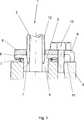
Einige Ausgestaltungen der erfindungsgemäßen Verbindungsanordnung werden nachfolgend anhand der Figuren näher erläutert. Diese zeigen, jeweils schematisch:Some embodiments of the connection arrangement according to the invention are explained in more detail below with reference to FIGS. These show, in each case schematically:
Der Konnektor ist aus Kunststoff ausgebildet, in dieser Ausgestaltung aus Polyamid-6 (PA-6). Das erste Rohr
Dem Radialflansch
Alternativ oder zusätzlich ist denkbar, die Dichtelemente
Das weitere Rohr
Der Radialflansch
Zur Herstellung der Verbindungsanordnung wird der Konnektor
Claims (13)
Translated fromGermanPriority Applications (8)
| Application Number | Priority Date | Filing Date | Title |
|---|---|---|---|
| DE202016100195.1UDE202016100195U1 (en) | 2016-01-15 | 2016-01-15 | Connecting arrangement for an air conditioner |
| PCT/EP2017/050594WO2017121818A1 (en) | 2016-01-15 | 2017-01-12 | Connection arrangement for an air conditioning system and mobile air conditioning system |
| CN201780007692.4ACN108778790A (en) | 2016-01-15 | 2017-01-12 | The attachment device of air-conditioning system and mobile air conditioner system |
| US16/069,976US20180370326A1 (en) | 2016-01-15 | 2017-01-12 | Connection arrangement for an air conditioning system and mobile air conditioning system |
| EP17700407.4AEP3402685B1 (en) | 2016-01-15 | 2017-01-12 | Connection arrangement for an air conditioning system and mobile air conditioning system |
| MX2018008713AMX2018008713A (en) | 2016-01-15 | 2017-01-12 | Connection arrangement for an air conditioning system and mobile air conditioning system. |
| KR1020187021870AKR102194614B1 (en) | 2016-01-15 | 2017-01-12 | Connecting device of air conditioning system and mobile air conditioning system |
| JP2018536425AJP6737890B2 (en) | 2016-01-15 | 2017-01-12 | Connection configuration of air conditioning system and mobile air conditioning system |
Applications Claiming Priority (1)
| Application Number | Priority Date | Filing Date | Title |
|---|---|---|---|
| DE202016100195.1UDE202016100195U1 (en) | 2016-01-15 | 2016-01-15 | Connecting arrangement for an air conditioner |
Publications (1)
| Publication Number | Publication Date |
|---|---|
| DE202016100195U1true DE202016100195U1 (en) | 2016-02-01 |
Family
ID=55358968
Family Applications (1)
| Application Number | Title | Priority Date | Filing Date |
|---|---|---|---|
| DE202016100195.1UActiveDE202016100195U1 (en) | 2016-01-15 | 2016-01-15 | Connecting arrangement for an air conditioner |
Country Status (8)
| Country | Link |
|---|---|
| US (1) | US20180370326A1 (en) |
| EP (1) | EP3402685B1 (en) |
| JP (1) | JP6737890B2 (en) |
| KR (1) | KR102194614B1 (en) |
| CN (1) | CN108778790A (en) |
| DE (1) | DE202016100195U1 (en) |
| MX (1) | MX2018008713A (en) |
| WO (1) | WO2017121818A1 (en) |
Families Citing this family (1)
| Publication number | Priority date | Publication date | Assignee | Title |
|---|---|---|---|---|
| KR20210125669A (en)* | 2020-04-09 | 2021-10-19 | 현대자동차주식회사 | Piping system for air conditioner |
Family Cites Families (30)
| Publication number | Priority date | Publication date | Assignee | Title |
|---|---|---|---|---|
| US4570983A (en)* | 1983-03-15 | 1986-02-18 | Arla | Pipe connection with a seal ring satisfying hygienic demands |
| JPH0219986U (en)* | 1988-07-16 | 1990-02-09 | ||
| US5354101A (en)* | 1993-09-13 | 1994-10-11 | General Motors Corporation | Sealing washer block connection |
| JPH0875074A (en)* | 1994-09-07 | 1996-03-19 | Kayaba Ind Co Ltd | Suction connector for pump |
| US5779280A (en)* | 1997-02-28 | 1998-07-14 | Mark Iv Automotive Aktiebolag | Fluid connector |
| JP2000009271A (en)* | 1998-06-19 | 2000-01-11 | Denso Corp | Fitting |
| EP1117959B1 (en)* | 1998-10-02 | 2007-07-18 | Parker-Hannifin Corporation | Coupling assembly |
| US6386593B1 (en)* | 1999-10-29 | 2002-05-14 | Automotive Fluid Systems, Inc. | Dual-plane seal for fluid-tight conduit connection |
| DE20007157U1 (en)* | 2000-04-19 | 2000-07-20 | Hansa Metallwerke Ag, 70567 Stuttgart | Fastening device for fastening two hose lines to a valve, in particular an expansion valve, a refrigeration system |
| JP2002054772A (en)* | 2000-08-07 | 2002-02-20 | Kurimoto Ltd | Pipe joint structure |
| US6908117B1 (en)* | 2000-10-06 | 2005-06-21 | Hutchinson Fts, Inc. | Block-conduit connection alignment device |
| JP2002147678A (en)* | 2000-11-09 | 2002-05-22 | Sekisui Chem Co Ltd | Header, and joining structure of header and piping material |
| JP4037647B2 (en)* | 2001-12-25 | 2008-01-23 | 三菱電線工業株式会社 | Jacket seal |
| JP2004092915A (en)* | 2002-03-20 | 2004-03-25 | Tokyo Electron Ltd | Pipe fitting |
| US7354079B2 (en)* | 2002-04-23 | 2008-04-08 | Watts Sea Tech, Inc. | Connector |
| DE10241921B3 (en)* | 2002-09-10 | 2004-01-29 | Eaton Fluid Power Gmbh | High-density connection device |
| DE102005020259A1 (en)* | 2005-04-30 | 2006-11-09 | Contitech Kühner Gmbh & Cie. Kg | Connection arrangement for refrigerant pipes |
| US7540539B2 (en)* | 2005-08-03 | 2009-06-02 | Eagle Industry Co., Ltd. | Pipe joint |
| JP2007040447A (en)* | 2005-08-04 | 2007-02-15 | Hiroshima Seiken Kogyo Kk | Pipe joint structure |
| US7766391B2 (en)* | 2006-04-05 | 2010-08-03 | Doowon Climate Control Co., Ltd. | Pipe connecting structure |
| US7621568B2 (en)* | 2006-04-25 | 2009-11-24 | Visteon Global Technologies, Inc. | Block fitting and seal structure |
| FR2901342B1 (en)* | 2006-05-18 | 2010-08-13 | Renault Sas | ARRANGEMENT FOR THE CLAMPING CONNECTION OF TWO CONDUITS |
| JP2011106607A (en)* | 2009-11-19 | 2011-06-02 | Sanoh Industrial Co Ltd | Pipe connecting structure |
| JP6056657B2 (en)* | 2012-06-22 | 2017-01-11 | 株式会社デンソー | Piping connection device and heat pump cycle device having the same |
| US9777878B2 (en)* | 2012-08-31 | 2017-10-03 | Hanon Systems | Connector |
| US20140252755A1 (en)* | 2013-03-08 | 2014-09-11 | Paccar Inc | Multipositional fitting |
| JP5862646B2 (en)* | 2013-12-04 | 2016-02-16 | トヨタ自動車株式会社 | Refrigerant tube connection structure and inverter with built-in cooler |
| DE202015103455U1 (en)* | 2015-07-01 | 2015-07-14 | Ti Automotive Engineering Centre (Heidelberg) Gmbh | Connecting element for connecting a pipe end to a component of an air conditioning system |
| US10344863B2 (en)* | 2017-08-30 | 2019-07-09 | Hanon Systems | Metal seal fitting for in-tank transmission oil cooler |
| US11060653B2 (en)* | 2018-08-09 | 2021-07-13 | Hanon Systems | Gap filling shipping cap for leveraged refrigerant fitting |
- 2016
- 2016-01-15DEDE202016100195.1Upatent/DE202016100195U1/enactiveActive
- 2017
- 2017-01-12KRKR1020187021870Apatent/KR102194614B1/ennot_activeExpired - Fee Related
- 2017-01-12EPEP17700407.4Apatent/EP3402685B1/enactiveActive
- 2017-01-12WOPCT/EP2017/050594patent/WO2017121818A1/ennot_activeCeased
- 2017-01-12MXMX2018008713Apatent/MX2018008713A/enunknown
- 2017-01-12USUS16/069,976patent/US20180370326A1/ennot_activeAbandoned
- 2017-01-12JPJP2018536425Apatent/JP6737890B2/enactiveActive
- 2017-01-12CNCN201780007692.4Apatent/CN108778790A/enactivePending
Also Published As
| Publication number | Publication date |
|---|---|
| JP2019502077A (en) | 2019-01-24 |
| CN108778790A (en) | 2018-11-09 |
| WO2017121818A8 (en) | 2018-02-08 |
| MX2018008713A (en) | 2018-09-21 |
| US20180370326A1 (en) | 2018-12-27 |
| KR20180098648A (en) | 2018-09-04 |
| KR102194614B1 (en) | 2020-12-24 |
| EP3402685B1 (en) | 2021-05-05 |
| WO2017121818A1 (en) | 2017-07-20 |
| JP6737890B2 (en) | 2020-08-12 |
| EP3402685A1 (en) | 2018-11-21 |
Similar Documents
| Publication | Publication Date | Title |
|---|---|---|
| DE202015103455U1 (en) | Connecting element for connecting a pipe end to a component of an air conditioning system | |
| CH667905A5 (en) | FLANGE CONNECTION FOR FIBER REINFORCED PLASTIC PIPE PARTS. | |
| EP1445529B1 (en) | Connection device for refrigerant conduits | |
| DE102015109268B4 (en) | Fitting with fastening element and method for producing a tight connection | |
| DE102010046542A1 (en) | Delivery pipe and method for producing a delivery pipe | |
| DE102022129718A1 (en) | Connection element for connecting lines for conducting a fluid | |
| DE102008025905B4 (en) | Fixing the ends of a bellows with an air spring | |
| DE202007009801U1 (en) | Arrangement for fluid-tight connection of two pipe ends made of different metals | |
| DE202007012050U1 (en) | Sealing element, in particular secondary sealing element of a mechanical seal | |
| DE202016100195U1 (en) | Connecting arrangement for an air conditioner | |
| DE102014216045A1 (en) | Connector for a hydraulic coupling system | |
| DE102013003401A1 (en) | Flat gasket for flange connections | |
| DE102011053208A1 (en) | Connection arrangement e.g. connector for pipe utilized in motor vehicle, has guiding element for generating guide between outer surface of tube and inner surface of fluid-guiding component during guiding of tube in component retainer | |
| EP4077999B1 (en) | Plug connector and plug connector assembly | |
| DE102014220012A1 (en) | Connecting element for connecting two hydraulic lines and hydraulic system | |
| DE102011012376A1 (en) | Tube-tube assembly | |
| EP1715221B1 (en) | Fixing of the end part of a bellow to a connecting part | |
| DE202011107927U1 (en) | Connecting device for connecting two pipes | |
| WO2017102124A1 (en) | Pipe connector | |
| DE102019113471A1 (en) | Connecting element for connecting two fluid lines or a fluid line to an aggregate | |
| DE102020006576A1 (en) | Arrangement with a front wall of a motor vehicle | |
| EP3344431B1 (en) | Pressure-medium unit, having a housing produced by injection molding and composed of plastic, and method for producing said pressure-medium unit | |
| DE102005051697A1 (en) | Plastics structural component of high strength and rigidity, useful e.g. in automobile construction, contains tubular inserted stiffening element(s) connected to the plastics using adhesion promoter | |
| DE202012003173U1 (en) | Molded part with at least one plug-in sleeve made of plastic and with an annular lip seal and pipe connection arrangement with such a molded part | |
| DE10216721B4 (en) | Connection system for the positive and / or non-positive connection of two components |
Legal Events
| Date | Code | Title | Description |
|---|---|---|---|
| R207 | Utility model specification | ||
| R163 | Identified publications notified | ||
| R150 | Utility model maintained after payment of first maintenance fee after three years | ||
| R151 | Utility model maintained after payment of second maintenance fee after six years | ||
| R081 | Change of applicant/patentee | Owner name:TI AUTOMOTIVE TECHNOLOGY CENTER GMBH, DE Free format text:FORMER OWNER: TI AUTOMOTIVE ENGINEERING CENTRE (HEIDELBERG) GMBH, 69123 HEIDELBERG, DE | |
| R152 | Utility model maintained after payment of third maintenance fee after eight years |