DE202015003062U1 - Monoaxialknochenschraube - Google Patents
MonoaxialknochenschraubeDownload PDFInfo
- Publication number
- DE202015003062U1 DE202015003062U1DE202015003062.9UDE202015003062UDE202015003062U1DE 202015003062 U1DE202015003062 U1DE 202015003062U1DE 202015003062 UDE202015003062 UDE 202015003062UDE 202015003062 U1DE202015003062 U1DE 202015003062U1
- Authority
- DE
- Germany
- Prior art keywords
- longitudinal direction
- clevis
- screw
- receiving opening
- fork head
- Prior art date
- Legal status (The legal status is an assumption and is not a legal conclusion. Google has not performed a legal analysis and makes no representation as to the accuracy of the status listed.)
- Expired - Lifetime
Links
Images


Classifications
- A—HUMAN NECESSITIES
- A61—MEDICAL OR VETERINARY SCIENCE; HYGIENE
- A61B—DIAGNOSIS; SURGERY; IDENTIFICATION
- A61B17/00—Surgical instruments, devices or methods
- A61B17/56—Surgical instruments or methods for treatment of bones or joints; Devices specially adapted therefor
- A61B17/58—Surgical instruments or methods for treatment of bones or joints; Devices specially adapted therefor for osteosynthesis, e.g. bone plates, screws or setting implements
- A61B17/68—Internal fixation devices, including fasteners and spinal fixators, even if a part thereof projects from the skin
- A61B17/70—Spinal positioners or stabilisers, e.g. stabilisers comprising fluid filler in an implant
- A61B17/7001—Screws or hooks combined with longitudinal elements which do not contact vertebrae
- A61B17/7032—Screws or hooks with U-shaped head or back through which longitudinal rods pass
- A—HUMAN NECESSITIES
- A61—MEDICAL OR VETERINARY SCIENCE; HYGIENE
- A61B—DIAGNOSIS; SURGERY; IDENTIFICATION
- A61B17/00—Surgical instruments, devices or methods
- A61B17/56—Surgical instruments or methods for treatment of bones or joints; Devices specially adapted therefor
- A61B17/58—Surgical instruments or methods for treatment of bones or joints; Devices specially adapted therefor for osteosynthesis, e.g. bone plates, screws or setting implements
- A61B17/68—Internal fixation devices, including fasteners and spinal fixators, even if a part thereof projects from the skin
- A61B17/84—Fasteners therefor or fasteners being internal fixation devices
- A61B17/86—Pins or screws or threaded wires; nuts therefor
- A61B17/8625—Shanks, i.e. parts contacting bone tissue
- A61B17/863—Shanks, i.e. parts contacting bone tissue with thread interrupted or changing its form along shank, other than constant taper
- A—HUMAN NECESSITIES
- A61—MEDICAL OR VETERINARY SCIENCE; HYGIENE
- A61B—DIAGNOSIS; SURGERY; IDENTIFICATION
- A61B17/00—Surgical instruments, devices or methods
- A61B17/56—Surgical instruments or methods for treatment of bones or joints; Devices specially adapted therefor
- A61B17/58—Surgical instruments or methods for treatment of bones or joints; Devices specially adapted therefor for osteosynthesis, e.g. bone plates, screws or setting implements
- A61B17/68—Internal fixation devices, including fasteners and spinal fixators, even if a part thereof projects from the skin
- A61B17/84—Fasteners therefor or fasteners being internal fixation devices
- A61B17/86—Pins or screws or threaded wires; nuts therefor
- A61B17/864—Pins or screws or threaded wires; nuts therefor hollow, e.g. with socket or cannulated
Landscapes
- Health & Medical Sciences (AREA)
- Orthopedic Medicine & Surgery (AREA)
- Life Sciences & Earth Sciences (AREA)
- Neurology (AREA)
- Surgery (AREA)
- Heart & Thoracic Surgery (AREA)
- Engineering & Computer Science (AREA)
- Biomedical Technology (AREA)
- Nuclear Medicine, Radiotherapy & Molecular Imaging (AREA)
- Medical Informatics (AREA)
- Molecular Biology (AREA)
- Animal Behavior & Ethology (AREA)
- General Health & Medical Sciences (AREA)
- Public Health (AREA)
- Veterinary Medicine (AREA)
- Surgical Instruments (AREA)
Abstract
Translated fromGermanDescription
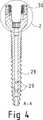
Translated fromGermanDie Erfindung betrifft eine Monoaxialknochenschraube mit einem ein Außengewinde aufweisenden Schaft und einem daran proximal und vorzugsweise einstückig anschließenden Gabelkopf, der also starr mit dem Schaft ausgebildet ist, wobei der Gabelkopf in einer Seitenansicht U-förmig ist und zwischen die U-Form bildenden Schenkeln eine Aufnahmeöffnung für ein Korrekturelement, insbesondere einen Korrekturstab, aufweist, wobei eine Längsrichtung und eine hierzu radiale Richtung gegeben ist, wobei die Aufnahmeöffnung in dem Gabelkopf ein distales Ende benachbart zu dem Schaft und ein hiervon in Längsrichtung abgewandtes offenes proximales Ende aufweist, in welches eine Klemmschraube für das Korrekturelement einschraubbar ist, wobei die Schenkel des Gabelkopfs hierfür ein Innengewinde tragen.The invention relates to a monoaxial bone screw with an externally threaded shaft and a proximally and preferably integrally adjoining clevis, which is thus rigidly formed with the shaft, wherein the clevis in a side view is U-shaped and between the U-forming legs forming a receiving opening for a correction element, in particular a correction rod, having a longitudinal direction and a radial direction thereto, wherein the receiving opening in the clevis has a distal end adjacent to the shaft and a longitudinally facing away from the open proximal end, in which a clamping screw for the correction element can be screwed in, the legs of the fork head for this purpose carry an internal thread.
Da der Gabelkopf bei Monoaxialknochenschrauben mit dem Schaft starr verbunden ist, wurden Monoaxialknochenschrauben mittels eines an den Schenkeln des Gabelkopfs angreifenden Einschraubinstruments ergriffen und in den Knochen des Patienten eingeschraubt.Since the clevis is rigidly connected to the shaft in monaxial bone screws, monoaxial bone screws were grasped by means of a screw-in instrument engaging the legs of the clevis and screwed into the patient's bone.
Der vorliegenden Erfindung liegt die Aufgabe zugrunde, die Handhabbarkeit einer Monoaxialknochenschraube der genannten Art zu verbessern.The present invention has for its object to improve the handling of a monoaxial bone screw of the type mentioned.
Diese Aufgabe wird ausgehend von einer solchen Monoaxialknochenschraube erfindungsgemäß dadurch gelöst, dass im Bereich des distalen Endes der Aufnahmeöffnung eine Werkzeugansetzstelle in Form einer zentrischen und in Längsrichtung erstreckten Vertiefung zur komplementären Aufnahme eines Werkzeugs ausgebildet ist, derart, dass die Schraube mittels des in die Vertiefung eingesetzten Werkzeugs um die Längsrichtung drehbar und hierdurch in den Knochen einschraubbar ist.This object is achieved on the basis of such a monoaxial bone screw according to the invention in that in the region of the distal end of the receiving opening a Werkzeugansetzstelle in the form of a central and longitudinally extending recess for complementary reception of a tool is formed, such that the screw by means of the inserted into the recess Tool is rotatable about the longitudinal direction and thereby screwed into the bone.
Es erweist sich von der Kinematik des Einschraubens her als vorteilhaft, wenn das Drehmoment mittels eines hierfür verwandten Instruments so nahe wie möglich am Schaft in die Knochenschraube eingeleitet wird. Dadurch dass erfindungsgemäß die Werkzeugansetzstelle im Bereich des distalen Endes der Aufnahmeöffnung des Gabelkopfs vorgesehen wird, kann dies erreicht werden. Ein weiterer Vorteil ist, dass zum Einschrauben der Monoaxialknochenschraube dasselbe Instrument wie zum Einschrauben einer Polyaxialknochenschraube verwendet werden kann, bei denen typischerweise am distalen Ende eines im Gabelkopfs verschwenkbaren Kopfs des Schafts eine Werkzeugansetzstelle vorgesehen ist.It turns out to be advantageous from the kinematics of screwing forth, when the torque is introduced by means of a related instrument as close as possible to the shaft in the bone screw. The fact that according to the invention the tool attachment point is provided in the region of the distal end of the receiving opening of the fork head, this can be achieved. Another advantage is that, for screwing in the monoaxial bone screw, the same instrument can be used as for screwing in a polyaxial bone screw, in which a tool attachment point is typically provided at the distal end of a head of the shaft which can be pivoted in the clevis.
In vorteilhafter Weise wird vorgeschlagen, dass die Werkzeugansetzstelle als Imbus- oder Torx-Werzeugansetzstelle ausgebildet ist.In an advantageous manner, it is proposed that the tool attachment point is designed as an imbus or Torx tool placement point.
Des Weiteren wird vorgeschlagen, dass die Werkzeugansetzstelle im Bereich des distalen Endes der Aufnahmeöffnung mit einer in Längsrichtung verlaufenden Öffnung in dem Schaft kommuniziert, wobei diese in Längsrichtung verlaufenden Öffnung in der Werkzeugansetzstelle proximal ausmündet und im Bereich des Schafts über Queröffnungen in radialer Richtung ausmündet sowie in Längsrichtung distal ausmündet.Furthermore, it is proposed that the tool attachment point in the region of the distal end of the receiving opening communicates with a longitudinal opening in the shaft, wherein this longitudinal opening in the tool attachment point opens out proximally and opens out in the region of the shaft via transverse openings in the radial direction and in Leads out longitudinally distally.
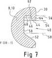
Weiter erweist es sich als vorteilhaft, dass die Schenkel einen radial äußeren Umfangsbereich aufweisen, der in einer Ebene orthogonal zur Längsrichtung des Gabelkopfs bogenförmig, insbesondere kreisbogenförmig gekrümmt ausgebildet ist und in dem zum Ergreifen des Gabelkopfs mittels eines Handhabungsinstruments jeweils wenigstens eine Haltenut ausgebildet ist, die sich in einer Umfangsrichtung des Gabelkopfs und in einer Ebene orthogonal zur Längsrichtung des Gabelkopfs erstreckt.Further, it proves to be advantageous that the legs have a radially outer peripheral portion which is arcuate in a plane orthogonal to the longitudinal direction of the clevis, in particular circular arc-shaped and in which for gripping the clevis by means of a handling instrument in each case at least one retaining groove is formed which extends in a circumferential direction of the clevis and in a plane orthogonal to the longitudinal direction of the clevis.
Weiter erweist es sich als vorteilhaft, dass die Haltenut in einer die Längsrichtung einschließenden gedachten Schnittebene betrachtet ausgehend von einer Oberfläche des Umfangsbereichs wenigstens abschnittsweise begrenzt ist
- – von einem ersten nach radial innen erstreckten und in einer Ebene orthogonal zur Längsrichtung des Gabelkopfs verlaufenden Flankenabschnitt,
- – daran anschließend von einem zweiten in proximaler Richtung erstreckten und konzentrisch zur Längsrichtung verlaufenden Flankenabschnitt,
- – daran anschließend von einem dritten nach radial innen erstreckten und in einer Ebene orthogonal zur Längsrichtung des Gabelkopfs verlaufenden Flankenabschnitt,
- – daran anschließend von einem vierten in distaler Richtung erstreckten und konzentrisch zur Längsrichtung verlaufenden Flankenabschnitt, der sich in distaler Richtung bis unter den ersten Flankenabschnitt erstreckt, und
- – daran anschließend von einem fünften mit einer Komponente nach radial außen erstreckten und in einer Ebene orthogonal zur Längsrichtung des Gabelkopfs oder in einem Winkel hierzu distal geneigt verlaufenden Flankenabschnitt.
- From a first flank section extending radially inwards and extending in a plane orthogonal to the longitudinal direction of the clevis,
- - Subsequently, by a second extending in the proximal direction and concentric with the longitudinal direction extending flank section,
- Subsequently from a third flank section, which extends radially inwards and runs in a plane orthogonal to the longitudinal direction of the clevis,
- - Subsequently, from a fourth extending in the distal direction and concentric with the longitudinal direction extending flank portion which extends in the distal direction to below the first flank portion, and
- - Subsequently, from a fifth with a component radially outwardly extending and in a plane orthogonal to the longitudinal direction of the clevis or at an angle thereto distally inclined flank portion extending.
Alternativ oder zusätzlich zu einer solchen Haltenut erweist es sich als vorteilhaft, wenn die Schenkel einen radial äußeren Umfangsbereich aufweisen, der bogenförmig, insbesondere kreisbogenförmig gekrümmt ausgebildet ist und in dem zum Ergreifen des Gabelkopfs mittels eines Handhabungsinstruments jeweils wenigstens eine in radialer Richtung erstreckte, vorzugsweise zylindrische Haltevertiefung ausgebildet ist.Alternatively, or in addition to such a retaining groove, it proves to be advantageous if the legs have a radially outer peripheral portion which is arcuate, in particular arcuately curved and in which for gripping the clevis by means of a handling instrument in each case at least one radially extending, preferably cylindrical Holding recess is formed.
Gegenstand der Erfindung ist auch eine Sachgesamtheit aus einer Monoaxialschraube nach einem oder mehreren der vorstehenden Ansprüche und einer Polyaxialschraube mit einem gegenüber dem Schaft polyaxial verschwenkbaren Gabelkopf, ebenfalls mit einer Aufnahmeöffnung für ein Korrekturelement, dadurch gekennzeichnet, dass die Werkzeugansetzstelle im Bereich des distalen Endes der Aufnahmeöffnung der Monoaxialschraube identisch zu einer Werkzeugansetzstelle im Bereich des distalen Endes der Aufnahmeöffnung der Polyaxialschraube ausgebildet ist. Weiter wird eine solche Sachgesamtheit mit einem Werkzeug für beide Schrauben beansprucht.The subject matter of the invention is also an aggregate of a monoaxial screw according to one or more of the preceding claims and a polyaxial screw with a relative to the shank polyaxial pivoting fork head, also with a receiving opening for a correction element, characterized in that the Werkzeugansetzstelle is formed in the region of the distal end of the receiving opening of the monoaxial screw identical to a Werkzeugansetzstelle in the region of the distal end of the receiving opening of the polyaxial screw , Furthermore, such an aggregate is claimed with a tool for both screws.
Weitere Merkmale, Einzelheiten und Vorteile der Erfindung ergeben sich aus den beigefügten Schutzansprüchen und aus der zeichnerischen Darstellung und nachfolgenden Beschreibung einer vorteilhaften Ausführungsform der vorliegenden Erfindung.Further features, details and advantages of the invention will become apparent from the appended claims and from the drawings and the following description of an advantageous embodiment of the present invention.
In der Zeichnung zeigt:In the drawing shows:
Die Figuren zeigen eine insgesamt mit dem Bezugszeichen
Der Gabelkopf
Die Aufnahmeöffnung
Der Schaft
Weiter ist in einem radial äußeren Umfangsbereich
Des Weiteren ist in dem jeweiligen radial äußeren Umfangsbereich
Die Haltenut
Claims (8)
Translated fromGermanPriority Applications (2)
| Application Number | Priority Date | Filing Date | Title |
|---|---|---|---|
| DE202015003062.9UDE202015003062U1 (en) | 2015-04-25 | 2015-04-25 | Monoaxialknochenschraube |
| EP16157414.0AEP3085320B1 (en) | 2015-04-25 | 2016-02-25 | Monoaxial bone screw |
Applications Claiming Priority (1)
| Application Number | Priority Date | Filing Date | Title |
|---|---|---|---|
| DE202015003062.9UDE202015003062U1 (en) | 2015-04-25 | 2015-04-25 | Monoaxialknochenschraube |
Publications (1)
| Publication Number | Publication Date |
|---|---|
| DE202015003062U1true DE202015003062U1 (en) | 2016-07-27 |
Family
ID=55446662
Family Applications (1)
| Application Number | Title | Priority Date | Filing Date |
|---|---|---|---|
| DE202015003062.9UExpired - LifetimeDE202015003062U1 (en) | 2015-04-25 | 2015-04-25 | Monoaxialknochenschraube |
Country Status (2)
| Country | Link |
|---|---|
| EP (1) | EP3085320B1 (en) |
| DE (1) | DE202015003062U1 (en) |
Families Citing this family (1)
| Publication number | Priority date | Publication date | Assignee | Title |
|---|---|---|---|---|
| US11583318B2 (en) | 2018-12-21 | 2023-02-21 | Paradigm Spine, Llc | Modular spine stabilization system and associated instruments |
Citations (9)
| Publication number | Priority date | Publication date | Assignee | Title |
|---|---|---|---|---|
| FR2820631A1 (en)* | 2001-02-15 | 2002-08-16 | Karim Benazzouz | Implant for feeding bone cement into fracture site has passage extending into screw with cross openings to discharge cement |
| US20070255284A1 (en)* | 2006-04-28 | 2007-11-01 | Sdgi Holdings, Inc. | Orthopedic implant apparatus |
| US20080132956A1 (en)* | 2006-11-10 | 2008-06-05 | Lutz Biedermann | Bone anchoring nail |
| DE212007000105U1 (en)* | 2007-08-24 | 2010-04-29 | Ihsan, Solaroglu | For cement injection suitable transpedicular screws |
| US20110288599A1 (en)* | 2010-05-19 | 2011-11-24 | Michael Michielli | Bone Anchors |
| US20120239091A1 (en)* | 2003-03-11 | 2012-09-20 | Lutz Biedermann | Anchoring element for use in spine or bone surgery, methods for use and production thereof |
| US20120330362A1 (en)* | 2007-07-20 | 2012-12-27 | Biedermann Technologies Gmbh & Co. Kg | Bone anchoring device |
| US20140163624A1 (en)* | 2011-08-02 | 2014-06-12 | NLT-Spine Ltd. | Bone Screw with Deflectable Portion |
| DE202004021979U1 (en)* | 2003-12-16 | 2014-10-15 | Medos International Sarl | Bone anchoring arrangements |
Family Cites Families (5)
| Publication number | Priority date | Publication date | Assignee | Title |
|---|---|---|---|---|
| US7621918B2 (en)* | 2004-11-23 | 2009-11-24 | Jackson Roger P | Spinal fixation tool set and method |
| US7678139B2 (en)* | 2004-04-20 | 2010-03-16 | Allez Spine, Llc | Pedicle screw assembly |
| US20070161985A1 (en)* | 2005-12-05 | 2007-07-12 | Kentomia, Llc . | Screws configured to engage bones, and methods of attaching implants to skeletal regions |
| US8911478B2 (en)* | 2012-11-21 | 2014-12-16 | Roger P. Jackson | Splay control closure for open bone anchor |
| EP2964116A4 (en)* | 2013-03-08 | 2016-11-23 | Anand K Agarwal | Pedicle screw assembly |
- 2015
- 2015-04-25DEDE202015003062.9Upatent/DE202015003062U1/ennot_activeExpired - Lifetime
- 2016
- 2016-02-25EPEP16157414.0Apatent/EP3085320B1/enactiveActive
Patent Citations (9)
| Publication number | Priority date | Publication date | Assignee | Title |
|---|---|---|---|---|
| FR2820631A1 (en)* | 2001-02-15 | 2002-08-16 | Karim Benazzouz | Implant for feeding bone cement into fracture site has passage extending into screw with cross openings to discharge cement |
| US20120239091A1 (en)* | 2003-03-11 | 2012-09-20 | Lutz Biedermann | Anchoring element for use in spine or bone surgery, methods for use and production thereof |
| DE202004021979U1 (en)* | 2003-12-16 | 2014-10-15 | Medos International Sarl | Bone anchoring arrangements |
| US20070255284A1 (en)* | 2006-04-28 | 2007-11-01 | Sdgi Holdings, Inc. | Orthopedic implant apparatus |
| US20080132956A1 (en)* | 2006-11-10 | 2008-06-05 | Lutz Biedermann | Bone anchoring nail |
| US20120330362A1 (en)* | 2007-07-20 | 2012-12-27 | Biedermann Technologies Gmbh & Co. Kg | Bone anchoring device |
| DE212007000105U1 (en)* | 2007-08-24 | 2010-04-29 | Ihsan, Solaroglu | For cement injection suitable transpedicular screws |
| US20110288599A1 (en)* | 2010-05-19 | 2011-11-24 | Michael Michielli | Bone Anchors |
| US20140163624A1 (en)* | 2011-08-02 | 2014-06-12 | NLT-Spine Ltd. | Bone Screw with Deflectable Portion |
Also Published As
| Publication number | Publication date |
|---|---|
| EP3085320B1 (en) | 2022-04-20 |
| EP3085320A1 (en) | 2016-10-26 |
Similar Documents
| Publication | Publication Date | Title |
|---|---|---|
| DE10157814B4 (en) | Closure device for securing a rod-shaped element in a holding element connected to a shaft | |
| DE69605285T2 (en) | DETACHABLE CLUTCH AND CORRESPONDING TOOL | |
| DE102016108504A1 (en) | Medical instrument for temporary fixation of a polyaxial pedicle screw | |
| EP2799023A1 (en) | Screwdriver for bone screws | |
| WO2019001990A1 (en) | EXTENDING DEVICE FOR A BONE ANCHOR | |
| EP3031416B1 (en) | Osteosynthesis device | |
| DE102015205362A1 (en) | Instrument for connecting a correction rod to a bone screw | |
| DE102020004179B4 (en) | Screw element and system consisting of a screwdriver and at least one such screw element | |
| EP4171409B1 (en) | Tool application point with orientation aid for screw elements | |
| EP3005962B1 (en) | Securing sleeve for a pedicle screw | |
| DE19625416A1 (en) | Screwdriver and screw for trauma and corrective facial or jaw surgery | |
| EP3085320B1 (en) | Monoaxial bone screw | |
| EP1563963A1 (en) | Screwdriver with holding device | |
| DE102013105744A1 (en) | Implantation screw and tool of an implantation set with relative rotation forcing | |
| DE3233133A1 (en) | CHUCK FOR A SHAFTED CUTTING TOOLS | |
| EP1539006A1 (en) | Intramedullary osteosynthesis pin for therapy of long bone fractures | |
| EP2945562B1 (en) | Shaft of a dental tool | |
| DE102017120620B4 (en) | Bone anchor and extension device | |
| DE102015214874A1 (en) | Handling instrument for a bone anchor | |
| DE102014108225A1 (en) | Locking screw and surgical screw system | |
| WO2015193178A1 (en) | Pedicle screw with screw-in aid | |
| EP2944267B1 (en) | Surgical suturing device | |
| DE102023121570B4 (en) | Screwdriver for an internal profile screw | |
| DE102005051545A1 (en) | toolholder | |
| DE102012204457A1 (en) | Auxiliary handgrip for drilling machine, has two sections connectable by releasable connection and formed from aluminum pipes, and clamping piece fixed on clamping neck of hand tool by screw that is guided through one section |
Legal Events
| Date | Code | Title | Description |
|---|---|---|---|
| R163 | Identified publications notified | ||
| R207 | Utility model specification | ||
| R150 | Utility model maintained after payment of first maintenance fee after three years | ||
| R151 | Utility model maintained after payment of second maintenance fee after six years | ||
| R152 | Utility model maintained after payment of third maintenance fee after eight years | ||
| R071 | Expiry of right |