DE202013103058U1 - jig - Google Patents
jigDownload PDFInfo
- Publication number
- DE202013103058U1 DE202013103058U1DE201320103058DE202013103058UDE202013103058U1DE 202013103058 U1DE202013103058 U1DE 202013103058U1DE 201320103058DE201320103058DE 201320103058DE 202013103058 UDE202013103058 UDE 202013103058UDE 202013103058 U1DE202013103058 U1DE 202013103058U1
- Authority
- DE
- Germany
- Prior art keywords
- cam mechanism
- tensioner
- cam
- clamped
- clamping
- Prior art date
- Legal status (The legal status is an assumption and is not a legal conclusion. Google has not performed a legal analysis and makes no representation as to the accuracy of the status listed.)
- Expired - Lifetime
Links
- 230000007246mechanismEffects0.000claimsabstractdescription38
- 239000011521glassSubstances0.000claimsdescription21
- 150000001875compoundsChemical class0.000claims1
- 230000008878couplingEffects0.000description2
- 238000010168coupling processMethods0.000description2
- 238000005859coupling reactionMethods0.000description2
- 239000000463materialSubstances0.000description2
- 238000000034methodMethods0.000description2
- 239000000047productSubstances0.000description2
- BUHVIAUBTBOHAG-FOYDDCNASA-N(2r,3r,4s,5r)-2-[6-[[2-(3,5-dimethoxyphenyl)-2-(2-methylphenyl)ethyl]amino]purin-9-yl]-5-(hydroxymethyl)oxolane-3,4-diolChemical compoundCOC1=CC(OC)=CC(C(CNC=2C=3N=CN(C=3N=CN=2)[C@H]2[C@@H]([C@H](O)[C@@H](CO)O2)O)C=2C(=CC=CC=2)C)=C1BUHVIAUBTBOHAG-FOYDDCNASA-N0.000description1
- 238000009412basement excavationMethods0.000description1
- 238000013016dampingMethods0.000description1
- 230000000694effectsEffects0.000description1
- 239000002184metalSubstances0.000description1
- 229910001220stainless steelInorganic materials0.000description1
- 239000010935stainless steelSubstances0.000description1
- 239000006228supernatantSubstances0.000description1
- 239000002023woodSubstances0.000description1
Images


Classifications
- F—MECHANICAL ENGINEERING; LIGHTING; HEATING; WEAPONS; BLASTING
- F16—ENGINEERING ELEMENTS AND UNITS; GENERAL MEASURES FOR PRODUCING AND MAINTAINING EFFECTIVE FUNCTIONING OF MACHINES OR INSTALLATIONS; THERMAL INSULATION IN GENERAL
- F16B—DEVICES FOR FASTENING OR SECURING CONSTRUCTIONAL ELEMENTS OR MACHINE PARTS TOGETHER, e.g. NAILS, BOLTS, CIRCLIPS, CLAMPS, CLIPS OR WEDGES; JOINTS OR JOINTING
- F16B2/00—Friction-grip releasable fastenings
- F16B2/02—Clamps, i.e. with gripping action effected by positive means other than the inherent resistance to deformation of the material of the fastening
- F16B2/18—Clamps, i.e. with gripping action effected by positive means other than the inherent resistance to deformation of the material of the fastening using cams, levers, eccentrics, or toggles
- F16B2/185—Clamps, i.e. with gripping action effected by positive means other than the inherent resistance to deformation of the material of the fastening using cams, levers, eccentrics, or toggles using levers
- B—PERFORMING OPERATIONS; TRANSPORTING
- B25—HAND TOOLS; PORTABLE POWER-DRIVEN TOOLS; MANIPULATORS
- B25B—TOOLS OR BENCH DEVICES NOT OTHERWISE PROVIDED FOR, FOR FASTENING, CONNECTING, DISENGAGING OR HOLDING
- B25B5/00—Clamps
- B25B5/06—Arrangements for positively actuating jaws
- B25B5/08—Arrangements for positively actuating jaws using cams
- B25B5/082—C-clamps
- B—PERFORMING OPERATIONS; TRANSPORTING
- B65—CONVEYING; PACKING; STORING; HANDLING THIN OR FILAMENTARY MATERIAL
- B65G—TRANSPORT OR STORAGE DEVICES, e.g. CONVEYORS FOR LOADING OR TIPPING, SHOP CONVEYOR SYSTEMS OR PNEUMATIC TUBE CONVEYORS
- B65G49/00—Conveying systems characterised by their application for specified purposes not otherwise provided for
- B65G49/05—Conveying systems characterised by their application for specified purposes not otherwise provided for for fragile or damageable materials or articles
- B65G49/06—Conveying systems characterised by their application for specified purposes not otherwise provided for for fragile or damageable materials or articles for fragile sheets, e.g. glass
- B65G49/061—Lifting, gripping, or carrying means, for one or more sheets forming independent means of transport, e.g. suction cups, transport frames
Landscapes
- Engineering & Computer Science (AREA)
- Mechanical Engineering (AREA)
- General Engineering & Computer Science (AREA)
- Clamps And Clips (AREA)
Abstract
Translated fromGermanDescription
Translated fromGermanBEZUGNAHME AUF IN ZUSAMMENHANG STEHENDES DOKUMENTREFER TO RELATED DOCUMENT
Diese Anmeldung beansprucht die Priorität der
TECHNISCHES GEBIETTECHNICAL AREA
Die Erfindung betrifft eine Spannvorrichtung, insbesondere eine Spannvorrichtung für die Verwendung mit zerbrechlichen Produkten, wie beispielsweise Glas.The invention relates to a clamping device, in particular a clamping device for use with fragile products, such as glass.
HINTERGRUND DER ERFINDUNGBACKGROUND OF THE INVENTION
Die Montage und Bewegung zerbrechlicher Produkte, wie beispielsweise Glas, wird in der Regel mit Hilfe von speziellen Werkzeugen durchgeführt. Zum Beispiel sind, wenn ein Duschtür aus Glas montiert wird, immer ein Hebel und ein Glasspanner erforderlich, um die Glastür zu befestigen und zu bewegen. Jedoch erfordert die Kopplung herkömmlicher Glasspanner mit Glas zusätzliche Befestigungsmittel, wie beispielsweise Schrauben oder Bolzen. Dadurch wird der Montagevorgang zeitaufwendig und er erfordert zusätzliche Werkzeuge, um die Montage fertig zu stellen. Darüber hinaus kann eine herkömmliche Glasspannvorrichtung nur zwischen einer vollständig freigegebenen Position und einer vollständig verriegelten Position betrieben werden, was für den Montagevorgang unkomfortabel ist.The assembly and movement of fragile products, such as glass, is usually done with the help of special tools. For example, when mounting a glass shower door, a lever and a glass vice are always required to secure and move the glass door. However, coupling glass glassware with glass requires additional fasteners such as screws or bolts. As a result, the assembly process is time consuming and he requires additional tools to complete the assembly. Moreover, a conventional glass chuck device can only be operated between a fully released position and a fully locked position, which is inconvenient for the assembly process.
DARSTELLUNG DER ERFINDUNGPRESENTATION OF THE INVENTION
Eine Aufgabe der Erfindung ist es, eine Spannvorrichtung bereit zu stellen, die kein zusätzliches Werkzeug benötigt, um ein Einspannen zu erreichen.An object of the invention is to provide a clamping device which does not require any additional tools to achieve clamping.
Eine weitere Aufgabe der Erfindung ist es, eine Spannvorrichtung bereitzustellen, welche zwischen einer vollständig freigegebenen Position, einer vorverriegelten Position und einer vollständig verriegelten Position betrieben werden kann, um die Montage zu erleichtern.Another object of the invention is to provide a tensioning device which can be operated between a fully released position, a pre-locked position and a fully locked position to facilitate assembly.
Um eine oder mehrere Aufgaben der vorliegenden Erfindung zu lösen, ist eine Spannvorrichtung vorgesehen, die eine Spannbasis und einen Nockenmechanismus aufweist. Die Spannbasis weist eine Öffnung zur Aufnahme zumindest eines Teils eines einzuspannenden Objekts und eine Ausnehmung zur Aufnahme des Nockenmechanismus auf. Der Nockenmechanismus ist in Bezug auf die Spannbasis drehbar zwischen einer ersten Position, in der die Spannvorrichtung das einzuspannende Objekt vollständig verriegelt, und einer zweiten Position, in der die Spannvorrichtung das Objekt vollständig freigibt.In order to accomplish one or more objects of the present invention, there is provided a tensioner having a tension base and a cam mechanism. The clamping base has an opening for receiving at least a part of an object to be clamped and a recess for receiving the cam mechanism. The cam mechanism is rotatable with respect to the clamping base between a first position in which the clamping device fully locks the object to be clamped and a second position in which the clamping device completely releases the object.
In einer bevorzugten Ausführungsform weist die Spannvorrichtung ferner ein flexibles Kissen auf, das sich innerhalb der Öffnung und in Benutzung zwischen der Spannbasis und dem einzuspannenden Objekt befindet. Das flexible Kissen ist dazu vorgesehen, das Einspannen des Objekts durch eine Erhöhung der Reibungskraft zwischen dem Objekt und dem Kissen zu verbessern. Das Kissen ist vorzugsweise mit Zähnen an einer oder beiden Seitenwänden in Richtung auf das Objekt hin versehen.In a preferred embodiment, the tensioning device further comprises a flexible pad located within the opening and in use between the tensioning base and the object to be clamped. The flexible pad is intended to enhance the clamping of the object by increasing the frictional force between the object and the pad. The pad is preferably provided with teeth on one or both side walls towards the object.
In einer bevorzugten Ausführungsform weist die Spannvorrichtung ferner ein steifes Kissen auf, welches sich in einer Seitenwand des flexiblen Kissens befindet und welches bei Verwendung an dem Nockenmechanismus anliegt. Vorzugsweise weist das steife Kissen einen seitlichen Flügel auf, um die Kontaktfläche derart zu vergrößern, dass das steife Kissen an einer Verschiebung gehindert wird.In a preferred embodiment, the tensioning device further comprises a rigid pad which is located in a side wall of the flexible pad and which in use bears against the cam mechanism. Preferably, the rigid pad has a lateral wing to increase the contact area such that the rigid pad is prevented from moving.
Gemäß einer Ausführungsform weist die Spannbasis ferner eine Verbindung auf, die zum Verbinden der Spannvorrichtung und des Objekts mit anderen Elementen verwendet wird. Die Verbindung erstreckt sich vorzugsweise seitlich von der Spannbasis.According to an embodiment, the clamping base further comprises a connection used to connect the tensioning device and the object to other elements. The connection preferably extends laterally from the clamping base.
Gemäß einer Ausführungsform umfasst die Spannvorrichtung zwei Seitenwände und eine mit den beiden Seitenwänden in Verbindung stehende obere Wand, welche die Öffnung definieren. Die obere Wand weist eine erste Aussparung und eine der beiden Seitenwände weist eine zweite Aussparung auf, und die ersten und zweiten Aussparungen definieren gemeinsam die Ausnehmung zur Aufnahme des Nockenmechanismus.According to one embodiment, the tensioning device comprises two side walls and an upper wall communicating with the two side walls, which define the opening. The upper wall has a first recess and one of the two side walls has a second recess, and the first and second recesses together define the recess for receiving the cam mechanism.
Gemäß einer Ausführungsform weist der Nockenmechanismus eine Stange, einen Nockenabschnitt und einen Verbindungsabschnitt auf, welcher die Stange mit dem Nockenabschnitt verbindet. Der Nockenabschnitt weist im Wesentlichen die Form eines Zylinders auf und weist eine vorstehende Oberfläche auf zumindest einem Teil einer äußeren Oberfläche des Zylinders auf.According to one embodiment, the cam mechanism comprises a rod, a cam portion and a connecting portion which connects the rod to the cam portion. The cam portion is substantially in the shape of a cylinder and has a protruding surface on at least a part of an outer surface of the cylinder.
In einer bevorzugten Ausführungsform weist der Nockenmechanismus eine Stange, einen Nockenabschnitt und einen Verbindungsabschnitt auf, welcher die Stange mit dem Nockenabschnitt verbindet. Der Nockenabschnitt weist im Wesentlichen die Form eines Zylinders auf und weist eine erste vorstehenden Oberfläche und eine zweite vorstehende Oberfläche auf zumindest einem Teil einer äußeren Oberfläche des Zylinders auf. Die erste vorstehende Oberfläche hat eine in Bezug auf die äußere Oberfläche geringere Höhe als die der zweiten vorstehenden Oberfläche. Die vorstehenden Oberflächen mit unterschiedlichen Höhen ermöglichen es, Vorverriegelung und vollständige Verriegelung des Objekts zu erreichen. In der vorverriegelten Position ist das Objekt nicht dazu in der Lage, sich frei zu bewegen, aber dennoch beweglich, wenn eine äußere Kraft darauf ausgeübt wird. In der vollständig verriegelten Position ist das Objekt vollständig unbeweglich.In a preferred embodiment, the cam mechanism comprises a rod, a cam portion, and a connecting portion connecting the rod to the cam portion. The cam portion is substantially in the shape of a cylinder and has a first protruding surface and a second protruding surface on at least a part of an outer surface of the cylinder. The first one above Surface has a lower height with respect to the outer surface than that of the second protruding surface. The protruding surfaces of different heights make it possible to achieve pre-locking and complete locking of the object. In the pre-locked position, the object is not able to move freely, but still movable when an external force is exerted thereon. In the fully locked position, the object is completely immobile.
Bevorzugt sind die ersten und zweiten vorstehenden Oberflächen nicht kontinuierlich. Die erste vorstehende Oberfläche weist vorzugsweise einen im Wesentlichen rechteckigen Abschnitt auf und die zweite vorstehende Oberfläche weist vorzugsweise einen im Wesentlichen bogenförmigen Abschnitt auf.Preferably, the first and second protruding surfaces are not continuous. The first projecting surface preferably has a substantially rectangular section, and the second projecting surface preferably has a substantially arcuate section.
Gemäß einer Ausführungsform besteht das einzuspannende Objekt aus Glas, Holz oder anderen geeigneten Materialien, vorzugsweise aus Glas.According to one embodiment, the object to be clamped is made of glass, wood or other suitable materials, preferably of glass.
Die durch die vorliegende Erfindung bereitgestellte Spannvorrichtung kann das Einspannen/Verriegeln eines Objekts ohne den Einsatz zusätzlicher Werkzeuge erreichen. Im bevorzugten Fall kann die Spannvorrichtung zwischen drei verschiedenen Positionen betrieben werden, nämlich einer vollständig freigegebenen Position, einer vorverriegelten Position und einer vollständig verriegelten Position, wodurch die Beherrschung und Handhabung des Objekts erleichtert wird.The tensioning device provided by the present invention can achieve the clamping / locking of an object without the use of additional tools. In the preferred case, the tensioning device may be operated between three different positions, namely a fully released position, a pre-locked position and a fully locked position, thereby facilitating the control and handling of the object.
KURZE BESCHREIBUNG DER ZEICHNUNGENBRIEF DESCRIPTION OF THE DRAWINGS
Elemente, die unerheblich für den Grundgedanken der Erfindung sind, sind aus Gründen der Übersichtlichkeit aus den Zeichnungen weggelassen.Elements which are immaterial to the basic idea of the invention have been omitted from the drawings for reasons of clarity.
AUSFÜHRLICHE BESCHREIBUNG DER ERFINDUNGDETAILED DESCRIPTION OF THE INVENTION
Die vorliegende Erfindung wird nun detaillierter unter Bezugnahme auf die Zeichnungen beschrieben. Es sei darauf hingewiesen, dass die hierin verwendete Terminologie nur dem Zweck der Beschreibung spezieller Ausführungsformen dient und nicht dazu gedacht ist, die Erfindung auf bestimmte Ausführungsbeispiele zu beschränken. Gemäß der Verwendung hierin sollen die Singularformen "ein", "eine" und "der" auch die Pluralformen umfassen, wenn der Zusammenhang nicht eindeutig etwas anderes angibt. Gemäß der Verwendung hierin umfassen die Begriffe "und/oder" jegliche und alle Kombinationen eines oder mehrerer der zugeordneten aufgelisteten Gegenstände. Es wird ferner darauf hingewiesen, dass die Begriffe "umfasst" "umfassend" "enthält" und/oder "enthaltend", wenn sie hierin verwendet werden, das Vorliegen der angegebenen Merkmale, Zahlen, Schritte, Operationen, Elemente und/oder Komponenten beschreiben, aber nicht das Vorliegen oder Hinzufügen eines oder mehrerer anderer Merkmale, Zahlen, Schritte, Operationen, Elemente, Komponenten und/oder Gruppen davon ausschließen.The present invention will now be described in more detail with reference to the drawings. It should be understood that the terminology used herein is for the purpose of describing particular embodiments only and is not intended to limit the invention to particular embodiments. As used herein, the singular forms "a," "an," and "the" are intended to include the plural forms, unless the context clearly indicates otherwise. As used herein, the terms "and / or" include any and all combinations of one or more of the associated listed items. It is further to be understood that the terms "comprising" "comprising" "containing" and / or "containing" when used herein, describing the presence of the specified features, numbers, steps, operations, elements and / or components, but do not preclude the presence or addition of one or more other features, numbers, steps, operations, elements, components, and / or groups thereof.
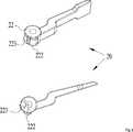
Unter Bezugnahme auf
Wie in
Der Nockenmechanismus
Der Nockenmechanismus
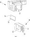
Unter Bezugnahme auf
Insbesondere dann, wenn die Spannbasis
In dem Beispiel sind die ersten und zweiten vorstehenden Oberflächen nicht-kontinuierlich, was vorteilhaft für die vollständige Erreichung der Vorverriegelungswirkung ist. Der Raum zwischen den vorstehenden Oberflächen kann von einem Fachmann bestimmt werden. In dem Beispiel weist die erste vorstehende Oberfläche
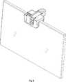
Unter Bezugnahme auf
Es sei darauf hingewiesen, dass verschiedene Ausführungsbeispiele unter Bezugnahme auf die beigefügten Zeichnungen beschrieben worden sind, in denen nur einige beispielhafte Ausführungsformen gezeigt sind. Die vorliegende Erfindung kann jedoch in vielen alternativen Formen ausgeführt werden und sollte nicht als auf nur die hierin dargelegten beispielhaften Ausführungsformen beschränkt ausgelegt werden.It should be understood that various embodiments have been described with reference to the accompanying drawings, in which only a few exemplary embodiments are shown. However, the present invention may be embodied in many alternative forms and should not be construed as limited to only the exemplary embodiments set forth herein.
ZITATE ENTHALTEN IN DER BESCHREIBUNG QUOTES INCLUDE IN THE DESCRIPTION
Diese Liste der vom Anmelder aufgeführten Dokumente wurde automatisiert erzeugt und ist ausschließlich zur besseren Information des Lesers aufgenommen. Die Liste ist nicht Bestandteil der deutschen Patent- bzw. Gebrauchsmusteranmeldung. Das DPMA übernimmt keinerlei Haftung für etwaige Fehler oder Auslassungen.This list of the documents listed by the applicant has been generated automatically and is included solely for the better information of the reader. The list is not part of the German patent or utility model application. The DPMA assumes no liability for any errors or omissions.
Zitierte PatentliteraturCited patent literature
- CN 201320337395[0001]CN 201320337395[0001]
Claims (10)
Translated fromGermanPriority Applications (1)
| Application Number | Priority Date | Filing Date | Title |
|---|---|---|---|
| DE201320103058DE202013103058U1 (en) | 2013-07-10 | 2013-07-10 | jig |
Applications Claiming Priority (1)
| Application Number | Priority Date | Filing Date | Title |
|---|---|---|---|
| DE201320103058DE202013103058U1 (en) | 2013-07-10 | 2013-07-10 | jig |
Publications (1)
| Publication Number | Publication Date |
|---|---|
| DE202013103058U1true DE202013103058U1 (en) | 2013-07-18 |
Family
ID=49029983
Family Applications (1)
| Application Number | Title | Priority Date | Filing Date |
|---|---|---|---|
| DE201320103058Expired - LifetimeDE202013103058U1 (en) | 2013-07-10 | 2013-07-10 | jig |
Country Status (1)
| Country | Link |
|---|---|
| DE (1) | DE202013103058U1 (en) |
Cited By (4)
| Publication number | Priority date | Publication date | Assignee | Title |
|---|---|---|---|---|
| EP2813447A1 (en)* | 2013-06-13 | 2014-12-17 | Foshan Ideal Co., Ltd. | Clamping devices |
| CN107121013A (en)* | 2017-06-23 | 2017-09-01 | 鲁苑凯 | Laser sight for pocket catapult |
| CN107976762A (en)* | 2017-12-26 | 2018-05-01 | 天津良益科技有限公司 | A kind of new optical bench |
| WO2025195870A1 (en)* | 2024-03-20 | 2025-09-25 | Gea Food Solutions Germany Gmbh | Fastening means for fastening at least one component to a support element of a device for processing food products, and device for processing food products having such a component |
- 2013
- 2013-07-10DEDE201320103058patent/DE202013103058U1/ennot_activeExpired - Lifetime
Cited By (4)
| Publication number | Priority date | Publication date | Assignee | Title |
|---|---|---|---|---|
| EP2813447A1 (en)* | 2013-06-13 | 2014-12-17 | Foshan Ideal Co., Ltd. | Clamping devices |
| CN107121013A (en)* | 2017-06-23 | 2017-09-01 | 鲁苑凯 | Laser sight for pocket catapult |
| CN107976762A (en)* | 2017-12-26 | 2018-05-01 | 天津良益科技有限公司 | A kind of new optical bench |
| WO2025195870A1 (en)* | 2024-03-20 | 2025-09-25 | Gea Food Solutions Germany Gmbh | Fastening means for fastening at least one component to a support element of a device for processing food products, and device for processing food products having such a component |
Similar Documents
| Publication | Publication Date | Title |
|---|---|---|
| DE10116821B4 (en) | Adjustable armrest assembly with a single lever | |
| DE202013102583U1 (en) | Door assembly | |
| DE202012103274U1 (en) | Drill holder for the manufacture of carpentry inclined bores and the same kit containing | |
| DE202013103058U1 (en) | jig | |
| DE102017127119A1 (en) | Device for positioning a window or a door | |
| DE202011004924U1 (en) | Device for holding hand-held equipment | |
| DE102014004238B4 (en) | robot system | |
| DE749654C (en) | Multi-part spacer clip | |
| DE69812244T2 (en) | Sectional roller unit for conveyor lines | |
| DE202011050924U1 (en) | Table in an interior of a motorhome | |
| DE202016102732U1 (en) | Device for straightening a quadrangular thin flat screen | |
| DE102016103520B3 (en) | Door frame arrangement and spacer for a Türzargenanordnung | |
| DE102012107587A1 (en) | Clamping tool and method | |
| DE202014104461U1 (en) | Arrangement for positioning a handle | |
| DE102013011085B4 (en) | easel use | |
| DE102018118772B4 (en) | socket holder frame assembly | |
| DE9301178U1 (en) | Device for marking wall holes and setting electrical installation elements | |
| DE102012010775A1 (en) | Cable clamp has swingable lever that is provided with swingable unit which is arranged with U-shaped support bracket to actuate pivoting movement of one of clamping units | |
| DE102007010565A1 (en) | Marking device in particular to be used in positioning of laminated floor elements, comprises sliding element with scale | |
| AT377721B (en) | ASSEMBLY DEVICE FOR CONNECTING DRAWER PARTS | |
| DE607210C (en) | Resilient pit stamp | |
| DE102022120688A1 (en) | Adjustable standoff fastener for a pipeline and arrangement with two standoff fasteners | |
| DE202014106065U1 (en) | Stand for hexagon wrench | |
| DE202015001329U1 (en) | Display device for a door | |
| DE102023121619A1 (en) | squeegee rubber, squeegee head and squeegee system |
Legal Events
| Date | Code | Title | Description |
|---|---|---|---|
| R207 | Utility model specification | Effective date:20130912 | |
| R156 | Lapse of ip right after 3 years |