DE202013101400U1 - Arrangement for converting the light emitted by an LED light source - Google Patents
Arrangement for converting the light emitted by an LED light sourceDownload PDFInfo
- Publication number
- DE202013101400U1 DE202013101400U1DE202013101400.1UDE202013101400UDE202013101400U1DE 202013101400 U1DE202013101400 U1DE 202013101400U1DE 202013101400 UDE202013101400 UDE 202013101400UDE 202013101400 U1DE202013101400 U1DE 202013101400U1
- Authority
- DE
- Germany
- Prior art keywords
- light
- color conversion
- conversion element
- arrangement
- light source
- Prior art date
- Legal status (The legal status is an assumption and is not a legal conclusion. Google has not performed a legal analysis and makes no representation as to the accuracy of the status listed.)
- Expired - Lifetime
Links
- 238000006243chemical reactionMethods0.000claimsabstractdescription86
- 238000000149argon plasma sinteringMethods0.000claimsdescription13
- 239000002096quantum dotSubstances0.000claimsdescription7
- 238000011144upstream manufacturingMethods0.000claimsdescription2
- 239000000463materialSubstances0.000description12
- 230000008878couplingEffects0.000description10
- 238000010168coupling processMethods0.000description10
- 238000005859coupling reactionMethods0.000description10
- ORQBXQOJMQIAOY-UHFFFAOYSA-NnobeliumChemical compound[No]ORQBXQOJMQIAOY-UHFFFAOYSA-N0.000description5
- 239000000853adhesiveSubstances0.000description4
- 230000001070adhesive effectEffects0.000description4
- 230000005284excitationEffects0.000description4
- 239000002245particleSubstances0.000description4
- 239000011248coating agentSubstances0.000description3
- 238000000576coating methodMethods0.000description3
- 239000000975dyeSubstances0.000description3
- 230000000694effectsEffects0.000description3
- 239000011521glassSubstances0.000description3
- 238000011161developmentMethods0.000description2
- 230000018109developmental processEffects0.000description2
- 238000007788rougheningMethods0.000description2
- 239000004480active ingredientSubstances0.000description1
- 239000003086colorantSubstances0.000description1
- 230000001419dependent effectEffects0.000description1
- 239000005357flat glassSubstances0.000description1
- 239000007850fluorescent dyeSubstances0.000description1
- 239000003292glueSubstances0.000description1
- 238000005286illuminationMethods0.000description1
- 239000002184metalSubstances0.000description1
- 239000004065semiconductorSubstances0.000description1
- QERYCTSHXKAMIS-UHFFFAOYSA-Mthiophene-2-carboxylateChemical compound[O-]C(=O)C1=CC=CS1QERYCTSHXKAMIS-UHFFFAOYSA-M0.000description1
Images

Classifications
- H—ELECTRICITY
- H10—SEMICONDUCTOR DEVICES; ELECTRIC SOLID-STATE DEVICES NOT OTHERWISE PROVIDED FOR
- H10H—INORGANIC LIGHT-EMITTING SEMICONDUCTOR DEVICES HAVING POTENTIAL BARRIERS
- H10H20/00—Individual inorganic light-emitting semiconductor devices having potential barriers, e.g. light-emitting diodes [LED]
- H10H20/80—Constructional details
- H10H20/85—Packages
- H10H20/851—Wavelength conversion means
- H10H20/8511—Wavelength conversion means characterised by their material, e.g. binder
- H10H20/8512—Wavelength conversion materials
- H—ELECTRICITY
- H10—SEMICONDUCTOR DEVICES; ELECTRIC SOLID-STATE DEVICES NOT OTHERWISE PROVIDED FOR
- H10H—INORGANIC LIGHT-EMITTING SEMICONDUCTOR DEVICES HAVING POTENTIAL BARRIERS
- H10H20/00—Individual inorganic light-emitting semiconductor devices having potential barriers, e.g. light-emitting diodes [LED]
- H10H20/80—Constructional details
- H10H20/85—Packages
- H10H20/851—Wavelength conversion means
- H10H20/8514—Wavelength conversion means characterised by their shape, e.g. plate or foil
- H—ELECTRICITY
- H10—SEMICONDUCTOR DEVICES; ELECTRIC SOLID-STATE DEVICES NOT OTHERWISE PROVIDED FOR
- H10H—INORGANIC LIGHT-EMITTING SEMICONDUCTOR DEVICES HAVING POTENTIAL BARRIERS
- H10H20/00—Individual inorganic light-emitting semiconductor devices having potential barriers, e.g. light-emitting diodes [LED]
- H10H20/80—Constructional details
- H10H20/85—Packages
- H10H20/855—Optical field-shaping means, e.g. lenses
- H10H20/856—Reflecting means
Landscapes
- Led Device Packages (AREA)
- Non-Portable Lighting Devices Or Systems Thereof (AREA)
Abstract
Translated fromGerman
Description
Translated fromGermanDie vorliegende Erfindung betrifft eine Anordnung zum Konvertieren des von einer LED-Lichtquelle emittierten Lichts sowie eine Leuchtvorrichtung, welche mindestens eine LED-Lichtquelle sowie eine entsprechende Anordnung aufweist.The present invention relates to an arrangement for converting the light emitted by an LED light source and a lighting device, which has at least one LED light source and a corresponding arrangement.
Aus dem Stand der Technik ist bekannt, das von LED-Lichtquellen abgegebene Licht zumindest teilweise in Licht einer anderen Wellenlänge umzusetzen. Grund hierfür ist, dass mit Hilfe von LEDs allein nicht Licht einer jeden beliebigen Farbe oder Farbtemperatur generiert werden kann. Bislang stehen lediglich Halbleiter zur Verfügung, die Licht in einigen wenigen Farben emittieren, wobei auch hier die Effizienz der Lichtabgabe stark schwankt. Eine bekannte Anordnung zur Lichtabgabe besteht deshalb oftmals in einer LED, die Licht im blauen Wellenlängenbereich, also Licht mit einer verhältnismäßig hohen Energie emittiert, wobei dieses Licht dann mit Hilfe eines Farbkonversionsmaterials zumindest teilweise in Licht einer anderen Wellenlänge umgesetzt wird. Als Mischlicht wird hierdurch letztendlich dann beispielsweise weißes Licht oder Licht einer anderen sich ergebenden Mischfarbe abgegeben. Das Farbkonversionsmaterial beinhaltet hierbei entsprechende Wirkstoffe, beispielsweise Fluoreszenzfarbstoffe bzw. Phosphore, die das von der LED stammende Licht absorbieren und mit einer anderen Wellenlänge wieder emittieren. Neuerdings erfolgt auch der Einsatz von Materialien, die sogenannte Quantendots beinhalten. Auch hierbei ergibt sich ein Material, welches zu den Farbstoffen vergleichbare Eigenschaften aufweist.It is known from the prior art to at least partially convert the light emitted by LED light sources into light of a different wavelength. The reason is that with the help of LEDs alone not light of any color or color temperature can be generated. So far, only semiconductors are available that emit light in a few colors, whereby the efficiency of the light output varies greatly here as well. A known arrangement for emitting light is therefore often in an LED, the light in the blue wavelength range, that emits light with a relatively high energy, which light is then converted by means of a color conversion material at least partially in light of a different wavelength. As a mixed light, this will eventually give off, for example, white light or light of another resulting mixed color. The color conversion material in this case contains corresponding active ingredients, for example fluorescent dyes or phosphors, which absorb the light originating from the LED and emit it at a different wavelength. Recently, the use of materials that include so-called quantum dots also takes place. Here, too, results in a material which has comparable properties to the dyes.
Bei einer derartigen Vorgehensweise zum Konvertieren des von einer Lichtquelle stammenden Lichts besteht selbstverständlich der Wunsch dahingehend, die Farbkonversion möglichst effizient zu gestalten. Insbesondere sollte möglichst wenig Licht verloren gehen, welches dann für die eigentliche Lichtabgabe nicht mehr genutzt werden kann. Ferner sollte der Farbkonversionsmaterial möglichst viel Licht hinsichtlich seiner Wellenlänge in der gewünschten Weise beeinflussen.Of course, in such an approach for converting the light originating from a light source, there is a desire to make the color conversion as efficient as possible. In particular, as little light as possible should be lost, which can then no longer be used for the actual light output. Furthermore, the color conversion material should influence as much light as possible in terms of its wavelength in the desired manner.
Der vorliegenden Erfindung liegt deshalb die Aufgabenstellung zugrunde, Anordnungen zum Konvertieren des von einer LED-Lichtquelle emittierten Lichts anzugeben, welche hinsichtlich ihrer Effizienz Vorteile gegenüber bislang bekannten entsprechenden Anordnungen aufweisen.The present invention is therefore based on the object to provide arrangements for converting the light emitted by an LED light source light, which have advantages in terms of their efficiency over previously known corresponding arrangements.
Die Aufgabe wird durch eine Anordnung zum Konvertieren des von einer LED-Lichtquelle emittierten Lichts mit den Merkmalen eines der unabhängigen Ansprüche gelöst. Vorteilhafte Weiterbildungen der Erfindung sind Gegenstand der abhängigen Ansprüche.The object is achieved by an arrangement for converting the light emitted by an LED light source with the features of one of the independent claims. Advantageous developments of the invention are the subject of the dependent claims.
Die nachfolgend beschriebenen Lösungen gehen dabei von zwei unterschiedlichen aus dem Stand der Technik bekannten Varianten aus, welche in erfindungsgemäßer Weise verbessert wurden.The solutions described below are based on two different known from the prior art variants, which have been improved in accordance with the invention.
Ausgangspunkt für eine erste erfindungsgemäße Lösung ist hierbei eine Anordnung, bei der dem Farbkonversionselement ein Lichtabstrahlelement nachgeordnet ist, welches an einer dem im Farbkonversionselement abgewandten Seite eine Lichtabstrahlfläche der Anordnung zum Konvertieren des Lichts bildet. Erfindungsgemäß ist hierbei vorgesehen, dass die Lichtabstrahlfläche des Lichtabstrahlelements strukturiert ist.The starting point for a first solution according to the invention here is an arrangement in which the color conversion element is followed by a Lichtabstrahlelement, which forms a Lichtabstrahlfläche the arrangement for converting the light on one side facing away in the color conversion element. According to the invention, it is provided here that the light emission surface of the light emission element is structured.
Gemäß einem ersten Aspekt der vorliegenden Erfindung wird deshalb eine Anordnung zum Konvertieren des von einer LED-Lichtquelle emittierten Lichts vorgeschlagen, welche ein Farbkonversionselement aufweist, das dazu ausgebildet ist, das von einer LED stammende Licht zumindest teilweise in Licht einer anderen Wellenlänge umzusetzen, sowie ein dem Farbkonversionselement nachgeordnetes, vorzugsweise plattenförmiges Lichtabstrahlelement, welches an einer dem Farbkonversionselement abgewandten Seite eine Lichtabstrahlfläche der Anordnung bildet, wobei erfindungsgemäß die Lichtabstrahlfläche strukturiert ist.Therefore, according to a first aspect of the present invention, there is proposed an arrangement for converting the light emitted from an LED light source having a color conversion element adapted to at least partially convert the light originating from one LED into light of a different wavelength the color conversion element downstream, preferably plate-shaped Lichtabstrahlelement, which forms a light emitting surface of the arrangement on a side facing away from the color conversion element, wherein according to the invention the light emitting surface is structured.
Eine ebenso bekannte Anordnung sieht vor, dass das Farbkonversionselement zwischen zwei im Wesentlichen plattenförmigen, lichtdurchlässigen Elementen angeordnet ist, wobei eines hiervon ein Lichteinkoppelelement bildet, welches an einer dem Farbkonversionselement abgewandten Seite eine Lichteinkoppelfläche der Anordnung bildet, und wobei das zweite Element ein Lichtabstrahlelement bildet, welches wiederum an einer dem Farbkonversionselement abgewandten Seite eine Lichtabstrahlfläche der Anordnung bildet. Bei dieser Ausführungsform ist erfindungsgemäß vorgesehen, dass die Lichteinkoppelfläche und/oder die Lichtabstrahlfläche der Anordnung strukturiert sind.A likewise known arrangement provides that the color conversion element is arranged between two substantially plate-shaped, translucent elements, one of which forms a light coupling element, which forms a light coupling surface of the arrangement on a side facing away from the color conversion element, and wherein the second element forms a Lichtabstrahlelement, which in turn forms a light emission surface of the arrangement on a side facing away from the color conversion element. In this embodiment, the invention provides that the light incidence surface and / or the light emission surface of the arrangement are structured.
Gemäß einem zweiten Aspekt der vorliegenden Erfindung wird dementsprechend eine Anordnung zum Konvertieren des von einer LED-Lichtquelle emittierten Lichts vorgeschlagen, welche ein Farbkonversionselement aufweist, welches dazu ausgebildet ist, das von einer LED stammende Licht zumindest teilweise in Licht einer anderen Wellenlänge umzusetzen, sowie ein dem Farbkonversionselement vorgeordnetes, vorzugsweise plattenförmiges Lichteinkoppelelement, welches an einer dem Farbkonversionselement abgewandten Seite eine Lichteinkoppelfläche der Anordnung bildet, sowie ein dem Farbkonversionselement nachgeordnetes, ebenfalls vorzugsweise plattenförmiges Lichtabstrahlelement, welches an einer dem Farbkonversionselement abgewandten Seite eine Lichtabstrahlfläche der Anordnung bildet, wobei erfindungsgemäß die Lichteinkoppelfläche und/oder die Lichtabstrahlfläche der Anordnung strukturiert sind.Accordingly, according to a second aspect of the present invention, there is provided an arrangement for converting the light emitted from an LED light source having a color conversion element adapted to at least partially convert the light originating from one LED into light of a different wavelength the color conversion element upstream, preferably plate-shaped Lichteinkoppelelement which on a side facing away from the color conversion element forms a Lichteinkoppelfläche the arrangement, and a color conversion element downstream, also preferably plate-shaped Lichtabstrahlelement which on a side facing away from the color conversion element a light emitting surface of the Form arrangement, wherein according to the invention, the light input surface and / or the light emitting surface of the arrangement are structured.
Die Strukturierung der Lichtabstrahlfläche und/oder der Lichteinkoppelfläche kann in unterschiedlicher Weise erfolgen, wobei beispielsweise denkbar wäre, zumindest eine der Flächen lichtstreuend zu strukturieren, z. B. aufzurauen. Je nachdem, an welcher Fläche die lichtstreuende Strukturierung vorgesehen ist, ergeben sich dann unterschiedliche Effekte, die allerdings beide zu einer Steigerung der Effizienz der Anordnung beitragen. Ist beispielsweise die Lichtabstrahlfläche lichtstreuend strukturiert, so hat dies zur Folge, dass ein Teil des Lichts an den streuenden Strukturen der Lichtabstrahlfläche zurückgeworfen wird in den Bereich des Farbkonversionselements. Es ergeben sich in diesem Fall also zumindest teilweise sogenannte Mehrfach-Reflexionen, welche insgesamt dazu führen, dass das Konversionselement effizienter genutzt werden kann und dementsprechend weniger Material hierfür erforderlich ist, als dies bei aus dem Stand der Technik bekannten Lösungen der Fall ist. Eine streuende Ausgestaltung der Lichteinkoppelfläche hingegen hat zur Folge, dass das von der LED-Lichtquelle stammende Licht bereits beim Lichteintritt in die Anordnung derart verteilt wird, dass es effizienter durch das Farbkonversionselement hindurch geleitet wird. Wiederum kann dieses also effizienter genutzt werden, so dass die angestrebte Lichtkonversion optimiert wird.The structuring of the light emitting surface and / or the light incoupling surface can take place in different ways, for example, it would be conceivable to structure at least one of the surfaces light scattering, z. B. roughen. Depending on which surface the light-scattering structuring is provided, then different effects arise, but both contribute to an increase in the efficiency of the arrangement. If, for example, the light-emitting surface is structured in a light-scattering manner, this has the consequence that a portion of the light at the scattering structures of the light-emitting surface is reflected back into the region of the color conversion element. Thus, in this case, so-called multiple reflections result at least in part, which overall lead to the conversion element being able to be used more efficiently and correspondingly less material being required for this purpose than is the case with solutions known from the prior art. On the other hand, a scattering configuration of the light incoupling surface has the result that the light originating from the LED light source is already distributed as it enters the arrangement in such a way that it is guided more efficiently through the color conversion element. Again, this can therefore be used more efficiently, so that the desired light conversion is optimized.
Alternativ zu einer lichtstreuenden Strukturierung könnte auch eine Mikroprismen-Struktur verwendet werden. Der Einsatz einer derartigen Struktur an der Lichtaustrittsfläche führt wiederum zu den bereits erwähnten vorteilhaften Mehrfach-Reflexionen, bei Einsatz an der Lichteintrittsfläche bewirkt die Struktur, dass das von der Lichtquelle abgegebene Anregungslicht effizienter eingekoppelt wird und an dieser Oberfläche auftretende Rückreflexionen vermieden werden. In beiden Fällen wird also wiederum eine Effizienzsteigerung erzielt, wobei beide Flächen nicht zwingend in gleicher Weise ausgeführt sein müssen sondern beispielsweise insbesondere auch eine Kombination von streuender Lichteintrittsfläche und mit Mikroprismen versehender Lichtaustrittsfläche bzw. umgekehrt denkbar wäre.As an alternative to a light-scattering structuring, a microprism structure could also be used. The use of such a structure at the light exit surface in turn leads to the already mentioned advantageous multiple reflections, when used at the light entry surface causes the structure that the light emitted by the light source excitation light is coupled more efficiently and occurring on this surface back reflections are avoided. In both cases, therefore, an increase in efficiency is again achieved, wherein both surfaces need not necessarily be carried out in the same way but, for example, in particular a combination of scattering light entry surface and micro prisms emitting light exit surface or vice versa is conceivable.
Für den Fall, dass das Farbkonversionselement zwischen zwei lichtdurchlässigen, plattenförmigen Elementen angeordnet ist, ist die LED-Lichtquelle außerhalb dieser Anordnung angeordnet. Alternativ hierzu könnte allerdings auch auf das Lichteinkoppelelement verzichtet werden, wobei dann beispielsweise denkbar wäre, die LED unmittelbar in das Farbkonversionselement einzubetten bzw. zu integrieren.In the event that the color conversion element is arranged between two translucent, plate-shaped elements, the LED light source is arranged outside this arrangement. Alternatively, however, could also be dispensed with the light coupling element, in which case, for example, would be conceivable to embed the LED directly into the color conversion element or to integrate.
Eine weitere erfindungsgemäße Anordnung zum Konvertieren des von einer LED-Lichtquelle stammenden Lichts basiert auf dem Einsatz eines Farbkonversionselements, bei dem das von der LED stammende Licht an einer ersten Fläche in dieses eingekoppelt wird und über eine zweite Fläche, die von der Lichteintrittsfläche getrennt und vorzugsweise in einem rechten Winkel hierzu ausgerichtet ist, wieder abgegeben wird. Zur Steigerung der Effizienz bei einer derartigen Anordnung ist aus dem Stand der Technik bekannt, zumindest die der Lichtaustrittsfläche gegenüberliegende Seite mit einer Verspiegelung zu versehen.A further arrangement according to the invention for converting the light originating from an LED light source is based on the use of a color conversion element in which the light originating from the LED is coupled in at a first surface and via a second surface which is separated from the light entry surface and preferably oriented at a right angle thereto, is discharged again. To increase the efficiency in such an arrangement, it is known from the prior art to provide at least the opposite side of the light exit surface with a mirror coating.
Ausgehend von dieser zweiten bekannten Anordnung wird nunmehr erfindungsgemäß vorgeschlagen, die Spiegelanordnung durch ein sogenanntes Metamaterial zu bilden. Dieses zeichnet sich dadurch aus, dass Licht nicht – wie bei einer gewöhnlichen spiegelnden Fläche – an der Oberfläche derart reflektiert wird, dass das bekannte Gesetz Einfallswinkel = Ausfallswinkel gilt. Stattdessen werden bei einem derartigen Material auftreffende Lichtstrahlen unabhängig von ihrem Einfallswinkel in entgegengesetzter Richtung zurückgeworfen. Der Einsatz eines derartigen spiegelnden Metamaterials hat zur Folge, dass der Verlust an Lichtstrahlen in dem Farbkonversionselement reduziert wird und damit wiederum dessen Effizienz gesteigert wird.Starting from this second known arrangement, it is now proposed according to the invention to form the mirror arrangement by a so-called metamaterial. This is characterized by the fact that light is not reflected on the surface - as in the case of an ordinary reflecting surface - in such a way that the known law of incident angle = angle of reflection applies. Instead, incident light rays are reflected in the opposite direction regardless of their angle of incidence with such a material. The use of such a reflective metamaterial has the consequence that the loss of light rays is reduced in the color conversion element and in turn its efficiency is increased.
Gemäß einem dritten erfindungsgemäßen Aspekt wird also eine Anordnung zum Konvertieren des von einer LED-Lichtquelle emittierten Lichts vorgeschlagen, welche ein Farbkonversionselement aufweist, welches dazu ausgebildet ist, das von einer LED stammende Licht zumindest teilweise in Licht einer anderen Wellenlänge umzusetzen, wobei das Farbkonversionselement zumindest eine erste Fläche, welche eine Lichteintrittsfläche für das Licht der LED-Lichtquelle bildet, sowie eine von der Lichteintrittsfläche getrennte, vorzugsweise in einem rechten Winkel hierzu ausgerichtete Lichtaustrittsfläche aufweist, und wobei eine der Lichtaustrittsfläche gegenüberliegende Seite des Elements mit einer Spiegelanordnung versehen ist. Erfindungsgemäß ist diese Spiegelanordnung durch ein Metamaterial gebildet.According to a third aspect of the invention, therefore, an arrangement is proposed for converting the light emitted by an LED light source having a color conversion element which is adapted to at least partially convert the light originating from one LED into light of a different wavelength, the color conversion element at least a first surface, which forms a light entry surface for the light of the LED light source, and a separate from the light entry surface, preferably aligned at a right angle thereto light exit surface, and wherein a light exit surface opposite side of the element is provided with a mirror arrangement. According to the invention, this mirror arrangement is formed by a metamaterial.
Vorzugsweise ist das Farbkonversionselement etwa quaderförmig ausgebildet, wobei abgesehen von der Lichteintrittsfläche und der Lichtaustrittsfläche ggf. auch alle weiteren Seiten des Farbkonversionselements mit einer Spiegelanordnung versehen sein können. Für die weiteren Flächen ist hierbei allerdings die Nutzung eines herkömmlich spiegelnden Materials ausreichend bzw. sogar vorteilhaft.Preferably, the color conversion element is approximately cuboid, wherein, apart from the light entry surface and the light exit surface, if necessary, all other sides of the color conversion element may be provided with a mirror arrangement. For the other areas, however, the use of a conventional reflective material is sufficient or even advantageous.
Die bei den erfindungsgemäßen Anordnungen zum Einsatz kommenden Farbkonversionselemente weisen wie bereits erwähnt ein Material auf, welches das von der LED-Lichtquelle stammende absorbiert und als Licht mit einem veränderten Wellenlängenbereich wieder abgibt. Es kann sich hierbei um Leuchtstoffe, sogenannte Phosphore, als auch um die bereits oben erwähnten Quantendots handeln.As already mentioned, the color conversion elements used in the arrangements according to the invention have a material which absorbs the light originating from the LED light source and emits it again as light with a changed wavelength range. It can be around Phosphors, as well as the above-mentioned quantum dots act.
Nachfolgend soll die Erfindung anhand der beiliegenden Zeichnung näher erläutert werden. Es zeigen:The invention will be explained in more detail with reference to the accompanying drawings. Show it:
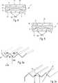
Als Ausgangspunkt für die ersten nachfolgend erläuterten erfindungsgemäßen Ausführungsbeispiele ist in
Für die Umwandlung des Lichts der LED-Lichtquelle
Das Farbkonversionselement
Nachfolgend werden verschiedene Varianten beschrieben, die in
Bei diesem ersten erfindungsgemäßen Ausführungsbeispiel in
Beispielsweise kann vorgesehen sein, dass von der LED
Ein zweites erfindungsgemäßes Ausführungsbeispiel einer Anordnung zum Konvertieren von Licht ist in
Bei der Variante von
Alternativ zu einer streuenden Strukturierung der Lichteinkoppelfläche und/oder der Lichtabstrahlfläche könnte allerdings auch eine Strukturierung mit Mikroprismen
Die Prismenstruktur an der Lichtaustrittsfläche
Auch die Nutzung derartiger Prismenstrukturen trägt also zur Steigung der Effizienz der Farbkonversion bei, wobei diese Prismenstrukturen mit den oben erwähnten lichtstreuenden Strukturen in beliebiger Weise kombiniert werden könnten. Das heißt, es wäre durchaus möglich, dass an der Lichteinkoppelfläche
Darüber hinaus wäre es auch denkbar, bei der erfindungsgemäßen Anordnung auf das Lichteinkoppelelement
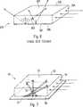
Für das nachfolgend beschriebene erfindungsgemäße Ausführungsbeispiel ist eine andere aus dem Stand der Technik bekannte Anordnung zum Farbkonvertieren von LED-Licht Ausgangspunkt. Diese bekannte Anordnung
Um zu verhindern, dass an der der Lichtaustrittsfläche
Gemäß der vorliegenden Erfindung ist zur Verbesserung dieser bekannten Anordnung vorgesehen, dass an Stelle der herkömmlichen Verspiegelung
Grundsätzlich entspricht der Aufbau der Anordnung
Diese besondere Art der Umlenkung auftreffender Lichtstrahlen hat zur Folge, dass weniger Strahlen als Verlustlicht über die Seitenflächen des Farbkonversionselements
In allen beschriebenen Varianten kann also im Vergleich zu aus dem Stand der Technik bekannten Lösungen die Effizienz bei der Umwandlung von Licht gesteigert werden. Die Effizienzsteigerung hat dabei insbesondere zur Folge, dass eine geringere Menge an Farbkonversionsmaterial erforderlich ist und Lichtverluste reduziert werden. Beide Vorteile tragen dazu bei, dass Lichtquellen auf LED-Basis in vielfältiger Weise zu Beleuchtungszwecken eingesetzt werden können.In all variants described, the efficiency in the conversion of light can thus be increased compared to solutions known from the prior art. The increase in efficiency has the consequence in particular that a smaller amount of color conversion material is required and light losses are reduced. Both advantages contribute to the fact that LED-based light sources can be used in a variety of ways for illumination purposes.
Claims (10)
Translated fromGermanPriority Applications (4)
| Application Number | Priority Date | Filing Date | Title |
|---|---|---|---|
| DE202013101400.1UDE202013101400U1 (en) | 2013-04-02 | 2013-04-02 | Arrangement for converting the light emitted by an LED light source |
| US14/781,837US20160043286A1 (en) | 2013-04-02 | 2014-04-01 | Arrangement for converting light emitted by an led light source |
| EP14714698.9AEP2981989B1 (en) | 2013-04-02 | 2014-04-01 | Arrangement for converting light emitted by an led light source |
| PCT/EP2014/056531WO2014161856A2 (en) | 2013-04-02 | 2014-04-01 | Arrangement for converting light emitted by an led light source |
Applications Claiming Priority (1)
| Application Number | Priority Date | Filing Date | Title |
|---|---|---|---|
| DE202013101400.1UDE202013101400U1 (en) | 2013-04-02 | 2013-04-02 | Arrangement for converting the light emitted by an LED light source |
Publications (1)
| Publication Number | Publication Date |
|---|---|
| DE202013101400U1true DE202013101400U1 (en) | 2014-07-03 |
Family
ID=50424249
Family Applications (1)
| Application Number | Title | Priority Date | Filing Date |
|---|---|---|---|
| DE202013101400.1UExpired - LifetimeDE202013101400U1 (en) | 2013-04-02 | 2013-04-02 | Arrangement for converting the light emitted by an LED light source |
Country Status (4)
| Country | Link |
|---|---|
| US (1) | US20160043286A1 (en) |
| EP (1) | EP2981989B1 (en) |
| DE (1) | DE202013101400U1 (en) |
| WO (1) | WO2014161856A2 (en) |
Families Citing this family (3)
| Publication number | Priority date | Publication date | Assignee | Title |
|---|---|---|---|---|
| CN105867026A (en)* | 2016-06-03 | 2016-08-17 | 青岛海信电器股份有限公司 | Quantum dot light source device, backlight module and liquid crystal display device |
| KR102664401B1 (en) | 2019-01-28 | 2024-05-08 | 삼성전자주식회사 | Light emitting device and display apparatus including the light emitting device |
| KR102692567B1 (en) | 2019-06-19 | 2024-08-06 | 삼성전자주식회사 | Light emitting device and display apparatus including the light emitting device |
Citations (5)
| Publication number | Priority date | Publication date | Assignee | Title |
|---|---|---|---|---|
| DE102007015474A1 (en)* | 2007-03-30 | 2008-10-02 | Osram Opto Semiconductors Gmbh | Electromagnetic radiation-emitting optoelectronic component and method for producing an optoelectronic component |
| DE102007059548A1 (en)* | 2007-09-28 | 2009-04-02 | Osram Opto Semiconductors Gmbh | Optoelectronic component and coupling-out lens for an optoelectronic component |
| DE102009058006A1 (en)* | 2009-12-11 | 2011-06-16 | Osram Opto Semiconductors Gmbh | Optoelectronic semiconductor device |
| DE102010005169A1 (en)* | 2009-12-21 | 2011-06-22 | OSRAM Opto Semiconductors GmbH, 93055 | Radiation-emitting semiconductor component |
| WO2011115515A1 (en)* | 2010-03-16 | 2011-09-22 | Общество с ограниченной ответственностью "ДиС ПЛЮС" | Method for controlling the chromaticity of a light flow from a white led and device for implementing said method |
Family Cites Families (27)
| Publication number | Priority date | Publication date | Assignee | Title |
|---|---|---|---|---|
| US4487481A (en)* | 1980-03-24 | 1984-12-11 | Epson Corporation | Backlighted liquid crystal display |
| JP3291972B2 (en)* | 1995-05-16 | 2002-06-17 | ソニー株式会社 | Liquid crystal display device and manufacturing method thereof |
| JP2004207065A (en)* | 2002-12-25 | 2004-07-22 | Fuji Electric Holdings Co Ltd | Color conversion light emitting device, method of manufacturing the same, and display using the device |
| JP3910926B2 (en)* | 2003-02-26 | 2007-04-25 | 株式会社東芝 | Method for producing transparent substrate for display device |
| US7074463B2 (en)* | 2003-09-12 | 2006-07-11 | 3M Innovative Properties Company | Durable optical element |
| EP1766690A1 (en)* | 2004-07-07 | 2007-03-28 | Saint-Gobain Glass France S.A. | Photovoltaic solar cell and solar module |
| JP4977021B2 (en)* | 2005-06-24 | 2012-07-18 | 出光興産株式会社 | Light diffusing plate and lighting device using the same |
| DE102005031523B4 (en)* | 2005-06-30 | 2015-11-05 | Schott Ag | Semiconductor light source with light conversion medium made of glass ceramic |
| US7418202B2 (en)* | 2005-08-04 | 2008-08-26 | 3M Innovative Properties Company | Article having a birefringent surface and microstructured features having a variable pitch or angles for use as a blur filter |
| US20070110386A1 (en)* | 2005-11-12 | 2007-05-17 | Tien-Hon Chiang | Device having combined diffusing, collimating, and color mixing light control function |
| US9134471B2 (en)* | 2006-06-28 | 2015-09-15 | 3M Innovative Properties Company | Oriented polymeric articles and method |
| JP2008034240A (en)* | 2006-07-28 | 2008-02-14 | Citizen Electronics Co Ltd | Backlight |
| KR101423456B1 (en)* | 2006-12-28 | 2014-07-29 | 서울반도체 주식회사 | A backlighting unit including a fluorescent film structure |
| DE102008021436A1 (en)* | 2008-04-29 | 2010-05-20 | Schott Ag | Optic converter system for (W) LEDs |
| KR101578250B1 (en)* | 2008-07-10 | 2015-12-16 | 쓰리엠 이노베이티브 프로퍼티즈 컴파니 | Retroreflective articles and devices having viscoelastic lightguide |
| WO2010025876A1 (en)* | 2008-09-04 | 2010-03-11 | Bayer Materialscience Ag | Light emitting device, and method for the production thereof |
| JP2010171342A (en)* | 2009-01-26 | 2010-08-05 | Sony Corp | Color conversion member, method of manufacturing the same, light-emitting device, and display |
| KR101520994B1 (en)* | 2009-02-26 | 2015-05-15 | 다이니폰 인사츠 가부시키가이샤 | Optical sheet, surface light source apparatus, transmission type display apparatus, and light emitter |
| CN102725868A (en)* | 2009-11-30 | 2012-10-10 | 京瓷株式会社 | Photoelectric conversion module, method for manufacturing same, and power generation device |
| JP5695085B2 (en)* | 2010-01-13 | 2015-04-01 | スリーエム イノベイティブ プロパティズ カンパニー | Lighting device with viscoelastic light guide |
| TWI561770B (en)* | 2010-04-30 | 2016-12-11 | Samsung Electronics Co Ltd | Light emitting device package, light source module, backlight unit, display apparatus, television set, and illumination apparatus |
| JP5566785B2 (en)* | 2010-06-22 | 2014-08-06 | 日東電工株式会社 | Composite sheet |
| JP5887936B2 (en)* | 2010-09-30 | 2016-03-16 | 三菱レイヨン株式会社 | Mold, light extraction substrate for surface light emitter, surface light emitter, protective plate for solar cell, and thin film solar cell |
| KR101832957B1 (en)* | 2011-05-31 | 2018-02-28 | 엘지전자 주식회사 | Micro shutter display device |
| TW201305487A (en)* | 2011-07-13 | 2013-02-01 | Rambus Inc | Lighting assembly with controlled configurable light redirection |
| JP2014197527A (en)* | 2013-03-04 | 2014-10-16 | 信越化学工業株式会社 | Vehicle direction indicator |
| MY177277A (en)* | 2014-03-03 | 2020-09-10 | Covalent Mat Corporation | Wavelength converting member |
- 2013
- 2013-04-02DEDE202013101400.1Upatent/DE202013101400U1/ennot_activeExpired - Lifetime
- 2014
- 2014-04-01USUS14/781,837patent/US20160043286A1/ennot_activeAbandoned
- 2014-04-01EPEP14714698.9Apatent/EP2981989B1/enactiveActive
- 2014-04-01WOPCT/EP2014/056531patent/WO2014161856A2/enactiveApplication Filing
Patent Citations (5)
| Publication number | Priority date | Publication date | Assignee | Title |
|---|---|---|---|---|
| DE102007015474A1 (en)* | 2007-03-30 | 2008-10-02 | Osram Opto Semiconductors Gmbh | Electromagnetic radiation-emitting optoelectronic component and method for producing an optoelectronic component |
| DE102007059548A1 (en)* | 2007-09-28 | 2009-04-02 | Osram Opto Semiconductors Gmbh | Optoelectronic component and coupling-out lens for an optoelectronic component |
| DE102009058006A1 (en)* | 2009-12-11 | 2011-06-16 | Osram Opto Semiconductors Gmbh | Optoelectronic semiconductor device |
| DE102010005169A1 (en)* | 2009-12-21 | 2011-06-22 | OSRAM Opto Semiconductors GmbH, 93055 | Radiation-emitting semiconductor component |
| WO2011115515A1 (en)* | 2010-03-16 | 2011-09-22 | Общество с ограниченной ответственностью "ДиС ПЛЮС" | Method for controlling the chromaticity of a light flow from a white led and device for implementing said method |
Also Published As
| Publication number | Publication date |
|---|---|
| WO2014161856A2 (en) | 2014-10-09 |
| WO2014161856A3 (en) | 2015-12-17 |
| EP2981989A2 (en) | 2016-02-10 |
| EP2981989B1 (en) | 2019-12-11 |
| US20160043286A1 (en) | 2016-02-11 |
Similar Documents
| Publication | Publication Date | Title |
|---|---|---|
| WO2012000737A1 (en) | Illuminated interior equipment component for a vehicle | |
| DE102004054732B4 (en) | Lichtleiteranordung | |
| EP2561270A1 (en) | Surface light source | |
| DE102004046256A1 (en) | Surface lighting system for rearward lighting of liquid crystal display, has light conductors for emitting electromagnetic radiation at its front side, and radiation sources positioned such that their optical axes cut each other | |
| DE102004002251A1 (en) | Luminaire with different colored light sources and a light guide plate for emitting mixed light | |
| EP2561388A2 (en) | Surface light guide and luminaire | |
| EP0533301A1 (en) | Advisory sign, illuminated from rear | |
| EP3158260B1 (en) | Motor vehicle lighting device | |
| EP2269901B1 (en) | Bar-shaped rear light for a bicycle | |
| EP2981989B1 (en) | Arrangement for converting light emitted by an led light source | |
| DE102017216259A1 (en) | Arrangement for emitting light | |
| EP2989381B1 (en) | Arrangement for light output comprising an led light source and a reflector | |
| DE102011007093A1 (en) | Illuminated tile-module for use at wall in toilet, has frame holding reflecting layer, light guide plate, LED, prism plate and glass plate, where LED illuminates light guide plate over edge of light guide plate | |
| EP2982903B1 (en) | Light assembly and lighting device equipped with the same | |
| DE102011000702A1 (en) | Tarmac road signs | |
| DE19831004A1 (en) | LED based lighting unit for use on body of road vehicle | |
| DE202012100991U1 (en) | Plate-shaped light guide and luminaire with light guide | |
| EP1335218A1 (en) | Lightguide arrangement and illumination device with said arrangement | |
| DE202005001507U1 (en) | Surface lighting system for rearward lighting of liquid crystal display, has light conductors for emitting electromagnetic radiation at its front side, and radiation sources positioned such that their optical axes cut each other | |
| EP4168711B1 (en) | Assembly for light emission, and luminaire | |
| EP1085252A2 (en) | Light guide luminaire comprising improved shielding means | |
| EP3329178B1 (en) | Optical waveguide element | |
| WO1990007765A1 (en) | Body with luminous data-display elements | |
| EP3128229A1 (en) | Lighting optics and luminaire comprising the lighting optics | |
| DE102022108996A1 (en) | LIGHT CONDUCTING ELEMENT, FOR EXAMPLE, FOR EXHAUST SIGN LIGHTS |
Legal Events
| Date | Code | Title | Description |
|---|---|---|---|
| R163 | Identified publications notified | ||
| R207 | Utility model specification | Effective date:20140814 | |
| R150 | Utility model maintained after payment of first maintenance fee after three years | ||
| R151 | Utility model maintained after payment of second maintenance fee after six years | ||
| R158 | Lapse of ip right after 8 years |