DE202013100574U1 - Mechanics for an office chair - Google Patents
Mechanics for an office chairDownload PDFInfo
- Publication number
- DE202013100574U1 DE202013100574U1DE202013100574.6UDE202013100574UDE202013100574U1DE 202013100574 U1DE202013100574 U1DE 202013100574U1DE 202013100574 UDE202013100574 UDE 202013100574UDE 202013100574 U1DE202013100574 U1DE 202013100574U1
- Authority
- DE
- Germany
- Prior art keywords
- mechanics
- support
- pivoting
- functional element
- backrest support
- Prior art date
- Legal status (The legal status is an assumption and is not a legal conclusion. Google has not performed a legal analysis and makes no representation as to the accuracy of the status listed.)
- Expired - Lifetime
Links
- 238000010276constructionMethods0.000claimsdescription18
- 230000008878couplingEffects0.000claimsdescription8
- 238000010168coupling processMethods0.000claimsdescription8
- 238000005859coupling reactionMethods0.000claimsdescription8
- 238000005096rolling processMethods0.000claimsdescription6
- 230000006835compressionEffects0.000description13
- 238000007906compressionMethods0.000description13
- BUHVIAUBTBOHAG-FOYDDCNASA-N(2r,3r,4s,5r)-2-[6-[[2-(3,5-dimethoxyphenyl)-2-(2-methylphenyl)ethyl]amino]purin-9-yl]-5-(hydroxymethyl)oxolane-3,4-diolChemical compoundCOC1=CC(OC)=CC(C(CNC=2C=3N=CN(C=3N=CN=2)[C@H]2[C@@H]([C@H](O)[C@@H](CO)O2)O)C=2C(=CC=CC=2)C)=C1BUHVIAUBTBOHAG-FOYDDCNASA-N0.000description1
- 239000000969carrierSubstances0.000description1
- 230000001419dependent effectEffects0.000description1
- 238000006073displacement reactionMethods0.000description1
- 239000007787solidSubstances0.000description1
- 230000001360synchronised effectEffects0.000description1
Images


Classifications
- A—HUMAN NECESSITIES
- A47—FURNITURE; DOMESTIC ARTICLES OR APPLIANCES; COFFEE MILLS; SPICE MILLS; SUCTION CLEANERS IN GENERAL
- A47C—CHAIRS; SOFAS; BEDS
- A47C7/00—Parts, details, or accessories of chairs or stools
- A47C7/36—Supports for the head or the back
- A47C7/40—Supports for the head or the back for the back
- A47C7/44—Supports for the head or the back for the back with elastically-mounted back-rest or backrest-seat unit in the base frame
- A47C7/441—Supports for the head or the back for the back with elastically-mounted back-rest or backrest-seat unit in the base frame with adjustable elasticity
- A—HUMAN NECESSITIES
- A47—FURNITURE; DOMESTIC ARTICLES OR APPLIANCES; COFFEE MILLS; SPICE MILLS; SUCTION CLEANERS IN GENERAL
- A47C—CHAIRS; SOFAS; BEDS
- A47C1/00—Chairs adapted for special purposes
- A47C1/02—Reclining or easy chairs
- A47C1/031—Reclining or easy chairs having coupled concurrently adjustable supporting parts
- A47C1/032—Reclining or easy chairs having coupled concurrently adjustable supporting parts the parts being movably-coupled seat and back-rest
- A47C1/03255—Reclining or easy chairs having coupled concurrently adjustable supporting parts the parts being movably-coupled seat and back-rest with a central column, e.g. rocking office chairs
- A—HUMAN NECESSITIES
- A47—FURNITURE; DOMESTIC ARTICLES OR APPLIANCES; COFFEE MILLS; SPICE MILLS; SUCTION CLEANERS IN GENERAL
- A47C—CHAIRS; SOFAS; BEDS
- A47C1/00—Chairs adapted for special purposes
- A47C1/02—Reclining or easy chairs
- A47C1/031—Reclining or easy chairs having coupled concurrently adjustable supporting parts
- A47C1/032—Reclining or easy chairs having coupled concurrently adjustable supporting parts the parts being movably-coupled seat and back-rest
- A47C1/03261—Reclining or easy chairs having coupled concurrently adjustable supporting parts the parts being movably-coupled seat and back-rest characterised by elastic means
- A47C1/03266—Reclining or easy chairs having coupled concurrently adjustable supporting parts the parts being movably-coupled seat and back-rest characterised by elastic means with adjustable elasticity
- A—HUMAN NECESSITIES
- A47—FURNITURE; DOMESTIC ARTICLES OR APPLIANCES; COFFEE MILLS; SPICE MILLS; SUCTION CLEANERS IN GENERAL
- A47C—CHAIRS; SOFAS; BEDS
- A47C1/00—Chairs adapted for special purposes
- A47C1/02—Reclining or easy chairs
- A47C1/031—Reclining or easy chairs having coupled concurrently adjustable supporting parts
- A47C1/032—Reclining or easy chairs having coupled concurrently adjustable supporting parts the parts being movably-coupled seat and back-rest
- A47C1/03261—Reclining or easy chairs having coupled concurrently adjustable supporting parts the parts being movably-coupled seat and back-rest characterised by elastic means
- A47C1/03272—Reclining or easy chairs having coupled concurrently adjustable supporting parts the parts being movably-coupled seat and back-rest characterised by elastic means with coil springs
- A—HUMAN NECESSITIES
- A47—FURNITURE; DOMESTIC ARTICLES OR APPLIANCES; COFFEE MILLS; SPICE MILLS; SUCTION CLEANERS IN GENERAL
- A47C—CHAIRS; SOFAS; BEDS
- A47C7/00—Parts, details, or accessories of chairs or stools
- A47C7/36—Supports for the head or the back
- A47C7/40—Supports for the head or the back for the back
- A47C7/44—Supports for the head or the back for the back with elastically-mounted back-rest or backrest-seat unit in the base frame
- A47C7/443—Supports for the head or the back for the back with elastically-mounted back-rest or backrest-seat unit in the base frame with coil springs
Landscapes
- Health & Medical Sciences (AREA)
- Dentistry (AREA)
- General Health & Medical Sciences (AREA)
- Chairs Characterized By Structure (AREA)
- Chairs For Special Purposes, Such As Reclining Chairs (AREA)
Abstract
Translated fromGerman
Description
Translated fromGermanDie Erfindung betrifft eine Mechanik für einen Bürostuhl, bei welcher der Schwenkwiderstand des Rückenlehnenträgers verändert werden kann. In der Regel ist hierzu eine Einstellung zwischen „hart” und „weich” wählbar, je nachdem, ob es sich bei dem Benutzer des Bürostuhles um eine schwere oder leichte Person handelt.The invention relates to a mechanism for an office chair, in which the pivoting resistance of the backrest support can be changed. As a rule, a setting between "hard" and "soft" can be selected, depending on whether the user of the office chair is a heavy or light person.
Aus
Eine Aufgabe der vorliegenden Erfindung ist es, eine Mechanik für einen Bürostuhl bereitzustellen, bei der ein kleiner Verstellweg ausreicht, um einen großen Verstellbereich des Schwenkwiderstandes der Rückenlehne zu verwirklichen.An object of the present invention is to provide a mechanism for an office chair in which a small displacement is sufficient to realize a large adjustment range of the swing resistance of the seat back.
Diese Aufgabe wird durch eine Mechanik nach Anspruch 1 gelöst. Vorteilhafte Ausführungen der Erfindung sind in den Unteransprüchen angegeben.This object is achieved by a mechanism according to
Danach ist es vorgesehen, die Mechanik derart auszugestalten, daß das Betätigungselement eine Auflage- und/oder Führungsbahn für das Funktionselement aufweist, dessen Lage auf der Auflage- und/oder Führungsbahn sich bei einer Lageänderung des Betätigungselements während eines Verschwenkens des Rückenlehnenträgers verändert. Darüber hinaus ist ein bewegliches Lenkerelement zur koppelnden Verbindung des Funktionselements mit einem weiteren Konstruktionselement der Mechanik vorgesehen, wobei das Lenkerelement die Art der Lageänderung des Funktionselements auf der Auflage- und/oder Führungsbahn während eines Verschwenkens des Rückenlehnenträgers bestimmt.Thereafter, it is envisaged to design the mechanism such that the actuating element has a support and / or guide track for the functional element whose position on the support and / or guide track changes during a change in position of the actuating element during a pivoting of the backrest support. In addition, a movable link element for coupling the functional element is provided with a further structural element of the mechanism, wherein the link element determines the type of change in position of the functional element on the support and / or guideway during pivoting of the backrest support.
Eine Kernidee der Erfindung ist es mit anderen Worten, daß das Betätigungselement selbst die Auflage- und/oder Führungsbahn für das Funktionselement bereitstellt, welches Funktionselement bei einem Verschwenken eine Änderung der Federspannung bewirkt. Da sich das Betätigungselement bei einem Verschwenken des Rückenlehnenträgers stets bewegt, vollführt damit zugleich auch die Auflage- und/oder Führungsbahn eine entsprechende Bewegung und beeinflußt daher die Lageänderung des Funktionselements, ohne daß dafür weitere konstruktive Maßnahmen erforderlich sind. Zugleich wird die Lage und die Bewegung des Funktionselements auf der Auflage- und/oder Führungsbahn während des Verschwenkens durch ein Lenkerelement erzwungen, welches Lenkerelement zwischen dem Funktionselement und einem weiteren Konstruktionselement der Mechanik angeordnet ist.A key idea of the invention is, in other words, that the actuating element itself provides the support and / or guideway for the functional element, which functional element causes a change in the spring tension during pivoting. Since the actuator always moves in a pivoting of the backrest support, at the same time also performs the support and / or guideway a corresponding movement and therefore influences the change in position of the functional element, without the need for further design measures are required. At the same time, the position and the movement of the functional element on the supporting and / or guideway during pivoting is forced by a link element, which link element is arranged between the functional element and a further structural element of the mechanism.
Eine solche Anordnung ermöglicht es, mit Hilfe einer einfach zu verwirklichenden ortsveränderlichen Verbindung des Lenkerelements mit dem weiteren Konstruktionselement der Mechanik, einen großen Verstellbereich des Schwenkwiderstandes der Rückenlehne bei einem kleinem Verstellweg zu verwirklichen. Daher benötigt die erfindungsgemäße Mechanik besonders wenig Bauraum für die Federkrafteinstellung.Such an arrangement makes it possible, with the aid of an easily realizable spatially variable connection of the link element with the further construction element of the mechanism, to realize a large adjustment range of the pivoting resistance of the backrest with a small adjustment path. Therefore, the mechanism of the invention requires very little space for the spring force adjustment.
Eine konstruktiv besonders einfache konstruktive Ausführung der Erfindung ist möglich, wenn das Betätigungselement fest mit dem Rückenlehnenträger verbunden ist. Es vollführt dann die Schwenkbewegung des Rückenlehnenträger 1:1 mit.A structurally particularly simple structural embodiment of the invention is possible if the actuating element is firmly connected to the backrest support. It then performs the pivoting movement of the backrest support 1: 1 with.
Als ganz besonders vorteilhaft hat sich eine Ausführungsform der Erfindung erwiesen, bei der das Funktionselement ein lageveränderlich gelagerter und von dem Betätigungselement direkt beaufschlagter Roll- oder Gleitkörper, vorzugsweise in Form eines zylindrischen Bolzens, ist. In einer solchen Ausführung läßt sich beim Verschwenken des Rückenlehnenträgers das die Erfindung auszeichnende, dynamische selbsttätige Positionieren des Funktionselements unter Einwirkung des Betätigungselements und gleichzeitiger Führung des Lenkerelements besonders einfach verwirklichen.As a particularly advantageous, an embodiment of the invention has been found, in which the functional element is a variable-position mounted and directly acted upon by the actuating element rolling or sliding body, preferably in the form of a cylindrical bolt. In such an embodiment, when pivoting the backrest support the invention distinguishing, dynamic automatic positioning of the functional element under the action of the actuating element and simultaneous guidance of the link element can be particularly easily realized.
Das Funktionselement umfaßt vorzugsweise ein Lager, wobei es sich um ein Wälzlager handelt, insbesondere in Form eines Kugel- oder Nadellagers. Selbstverständlich können jedoch auch andere Lagervorrichtungen, beispielsweise Gleitlager, zum Einsatz kommen.The functional element preferably comprises a bearing, which is a roller bearing, in particular in the form of a ball or needle bearing. Of course, however, other storage devices, such as plain bearings, are used.
Das Lenkerelement stützt sich in einer Ausführungsform der Erfindung an dem weiteren Konstruktionselement der Mechanik lediglich ab, ohne mit dem weiteren Konstruktionselement ortsfest verbunden zu sein. Im einfachsten Fall liegt das Lenkerelement als in sich starres Bauelement zwischen dem Funktionselement und dem weiteren Konstruktionselement der Mechanik ein, dabei seine Position selbsttätig haltend. Hierzu ist das Lenkerelement in einer Ausführungsform der Erfindung mit seinem einen Ende an dem Funktionselement angelenkt und mit seinem gegenüberliegenden Ende gegen eine Aufnahme in dem weiteren Konstruktionselement verklemmt.The link element is based in one embodiment of the invention on the further structural element of the mechanism only from without being connected to the other structural element stationary. In the simplest case, the link element is in itself a rigid component between the functional element and the further structural element of the mechanism, while maintaining its position automatically. For this purpose, the link element is articulated in one embodiment of the invention with its one end to the functional element and jammed with its opposite end against a receptacle in the further construction element.
Stützt sich das Lenkerelement lediglich an dem weiteren Konstruktionselement ab, dann ist es auf besonders einfache Art und Weise möglich, die Verbindung von Lenkerelement an dem weiteren Konstruktionselement ortsveränderlich auszuführen. Eine ortsveränderliche Verbindung des Lenkerelements an dem weiteren Konstruktionselement ist aber auch möglich, wenn das Lenkerelement auf andere Weise mit dem weiteren Konstruktionselement verbunden ist. Eine Änderung des Verbindungsortes während einer Verstellung der Federkraft von „weich” nach „hart” oder umgekehrt bewirkt erfindungsgemäß eine veränderte Lageänderung des Funktionselements auf der Auflage- und/oder Führungsbahn während eines Verschwenkens des Rückenlehnenträgers und damit eine Veränderung des Schwenkwiderstandes der Rückenlehne. If the link element is only supported on the further construction element, then it is possible in a particularly simple manner to carry out the connection of the link element to the further construction element in a mobile manner. However, a movable connection of the link element to the further construction element is also possible if the link element is connected in a different manner to the further construction element. A change in the connection location during an adjustment of the spring force from "soft" to "hard" or vice versa causes a changed change in position of the functional element on the support and / or guideway during pivoting of the backrest support and thus a change in the pivoting resistance of the backrest.
In einer Ausführungsform weist das weitere Konstruktionselement eine Anzahl von aneinander angrenzenden Aufnahmen auf, in die das dem weiteren Konstruktionselement zugeordnete Ende des Lenkerelements nacheinander hineinbewegt werden kann. Dadurch wird eine Verstelleinrichtung zur nichtkontinuierlichen, diskreten Änderung des Schwenkwiderstandes geschaffen. Als Verstellelement dient in einer Ausführungsform der Erfindung ein mit demjenigen Ende des Lenkerelements, welches dem weiteren Konstruktionselement zugeordnet ist, verbundenes Zugmittel, vorzugsweise in Form eines Bowdenzuges.In one embodiment, the further construction element has a number of mutually adjacent receptacles into which the end of the link element associated with the further construction element can be successively moved. As a result, an adjusting device for non-continuous, discrete change of the pivoting resistance is created. As an adjusting element is used in one embodiment of the invention with a that end of the link element, which is assigned to the further construction element, connected traction means, preferably in the form of a Bowden cable.
In einer Ausführungsform der Erfindung sind die an dem weiteren Konstruktionselement vorgesehenen Aufnahmen derart angeordnet, daß das Lenkerelement auf einer Kreisbahn um seinen Anlenkpunkt an dem Funktionselement verschwenkt werden kann, ohne daß die Verbindung zwischen dem Lenkerelement und dem weiteren Konstruktionselement gelöst wird. Während der Lageänderung des Lenkerelements mit Hilfe der Verstelleinrichtung bleibt die Kopplung zwischen Funktionselement und dem weiteren Konstruktionselement daher stets aufrechterhalten. Darüber hinaus wirkt die Federkraft, die von dem Federmechanismus auf das mit dem Federmechanismus in Wirkverbindung stehende bewegliche Funktionselement aufgebracht wird, vorzugsweise senkrecht auf die von dem Betätigungselement bereitgestellte Auflage- und/oder Führungsbahn. Im Ergebnis kann der Ort der Verbindung des Lenkerelements mit dem weiteren Konstruktionselement der Mechanik verändert werden, ohne daß es zu einer wesentlichen Änderung der Lage des Funktionselements auf der Auflage- und/oder Führungsbahn kommt. Daher muß bei der Einstellung der Federkraft im unverschwenkten Zustand der Rückenlehne gar nicht oder nur in einem sehr geringen Ausmaß gegen die Kraft des wenigstens einen Federelements des Federmechanismus gearbeitet werden. Es ist daher eine besonders leichtgängige Federkrafteinstellung möglich.In one embodiment of the invention, the receptacles provided on the further construction element are arranged such that the link element can be pivoted on a circular path about its articulation point on the functional element, without the connection between the link element and the further construction element is released. During the change in position of the link element by means of the adjusting device, the coupling between the functional element and the further construction element therefore always remains maintained. In addition, the spring force applied by the spring mechanism to the movable functional element operatively connected to the spring mechanism preferably acts perpendicular to the support and / or guideway provided by the actuator. As a result, the location of the connection of the link element with the further structural element of the mechanism can be changed, without causing a significant change in the position of the functional element on the support and / or guideway. Therefore, when adjusting the spring force in the untwisted state of the backrest must not be worked or only to a very small extent against the force of the at least one spring element of the spring mechanism. It is therefore possible a particularly smooth spring force adjustment.
Eine konstruktiv besonders einfache konstruktive Ausführung der Erfindung ist möglich, wenn es sich bei dem weiteren Konstruktionselement der Mechanik um einen Teil des Basisträgers handelt.A structurally particularly simple structural embodiment of the invention is possible if the further construction element of the mechanism is a part of the base support.
Durch die Lageänderung des Betätigungselements während eines Verschwenkens der Rückenlehne und die dadurch hervorgerufene Lageänderung des Funktionselements wird erfindungsgemäß die Spannung des wenigstens einen Federelements verändert. Im Federmechanismus können für die Zwecke der vorliegenden Erfindung beliebige Arten von Federelementen verwendet werden. Als besonders vorteilhaft haben sich wegen ihrer Einfachheit und Robustheit Schraubenfedern, insbesondere in Form von Schraubendruckfedern bewährt. Wird eine Schraubendruckfeder verwendet, ist das Funktionselement vorzugsweise ein mittelbar oder unmittelbar an einem Ende der Feder, vorzugsweise an einem Federteller, angreifendes Bauelement.Due to the change in position of the actuating element during a pivoting of the backrest and the resulting change in position of the functional element, the voltage of the at least one spring element is changed according to the invention. In the spring mechanism, any types of spring members may be used for the purposes of the present invention. Be particularly advantageous because of their simplicity and robustness coil springs, especially proven in the form of helical compression springs. If a helical compression spring is used, the functional element is preferably a component acting directly or indirectly on one end of the spring, preferably on a spring plate.
Die Auflage- und/oder Führungsbahn kann im einfachsten Fall die Form eines Kreisbogenabschnitts aufweisen. Variationen in der Konkavität der Lagerfläche, beispielsweise anfangs flach, später steiler werdend etc., sind möglich und haben ein anderes dynamisches Federverhalten zur Folge.The support and / or guide track can in the simplest case have the shape of a circular arc section. Variations in the concavity of the bearing surface, for example, initially flat, later steeper etc., are possible and have a different dynamic spring behavior result.
Der mit dem Rückenlehnenträger des Bürostuhls in Wirkverbindung stehende Federmechanismus kann sowohl direkt oder indirekt mit dem Rückenlehnenträger verbunden sein. Bei einer indirekten Verbindung ist der Federmechanismus vorzugsweise über den Sitzträger als Koppelelement mit dem Rückenlehnenträger verbunden. Die konkrete konstruktive Ausführung ist von dem Aufbau des Bürostuhls und der Art der Mechanik (Synchronmechanik, Asynchronmechanik) abhängig.The spring mechanism operatively connected to the backrest support of the office chair can be connected to the backrest support both directly or indirectly. In an indirect connection, the spring mechanism is preferably connected via the seat support as a coupling element with the backrest support. The concrete design is dependent on the structure of the office chair and the type of mechanics (synchronous mechanism, asynchronous mechanism).
Ein Ausführungsbeispiel der Erfindung wird nachfolgend anhand der Zeichnungen näher erläutert. Hierbei zeigen:An embodiment of the invention will be explained in more detail with reference to the drawings. Hereby show:
Sämtliche Figuren zeigen die Erfindung lediglich schematisch und mit ihren wesentlichen Bestandteilen. Gleiche Bezugszeichen entsprechen dabei Elementen gleicher oder vergleichbarer Funktion.All figures show the invention only schematically and with its essential components. The same reference numerals correspond to elements of the same or comparable function.
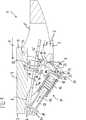
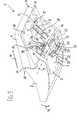
Die Abbildungen zeigen Teile einer Schwenkmechanik
Die Schwenkmechanik
Das vordere Ende
Der Rückenlehnenträger
Der Federmechanismus
Mit dem Funktionselement
Die Aufnahme
Die Aufnahmen
Bei einer Verschwenkung des Rückenlehnenträgers
In dem in
Wird mit Hilfe des Bowdenzuges
Bei einem Verschwenken des Rückenlehnenträgers
Insgesamt ergibt sich trotz des nur kleinen Verstellweges zwischen der hintersten Aufnahme
Alle in der Beschreibung, den nachfolgenden Ansprüchen und den Zeichnungen dargestellten Merkmale können sowohl einzeln als auch in beliebiger Kombination miteinander erfindungswesentlich sein.All in the description, the following claims and the drawings illustrated features may be essential to the invention both individually and in any combination.
BezugszeichenlisteLIST OF REFERENCE NUMBERS
- 11
- Schwenkmechanikswivel mechanism
- 22
- Basisträgerbase support
- 33
- Konusaufnahmecone holder
- 44
- Sitzträgerseat support
- 55
- RückenlehnenträgerBackrest support
- 66
- vorderes Ende des Basisträgersfront end of the basic carrier
- 77
- vorderes Ende des Sitzträgersfront end of the seat carrier
- 88th
- Dreh-/SchiebegelenkRotary / sliding joint
- 99
- HauptschwenkachseMain pivot axis
- 10 10
- 1111
- StuhllängsrichtungChair longitudinally
- 1212
- hinteres Ende des Sitzträgersrear end of the seat support
- 1313
- Lagerpunktbearing point
- 1414
- vorderes Ende des Rückenlehnenträgersfront end of the backrest support
- 1515
- Federmechanismusspring mechanism
- 1616
- SchraubendruckfederHelical compression spring
- 1717
- Führungseinrichtungguide means
- 1818
- Führungsstangeguide rod
- 1919
- Federtellerspring plate
- 2020
- Federtellerspring plate
- 2121
- festes Ende der Federsolid end of the spring
- 2222
- Funktionselement, Roll- und/oder GleitkörperFunctional element, rolling and / or sliding body
- 2323
- bewegliches Ende der Federmovable end of the spring
- 2424
- Achse des FunktionselementsAxis of the functional element
- 2525
- Auflage- und/oder FührungsbahnSupport and / or guideway
- 2626
- 2727
- Nadellagerneedle roller bearings
- 2828
- Schwenkhebelpivoting lever
- 2929
- festes Ende der Koppeltight end of the paddock
- 3030
- 3131
- Koppelpaddock
- 3232
- Lascheflap
- 3333
- bewegliches Ende/Freiende der Koppelmoving end / free end of the paddock
- 3434
- Klemmbolzenclamping bolts
- 3535
- Mittellängsachsecentral longitudinal axis
- 3636
- Lascheflap
- 3737
- Aufnahmeadmission
- 3838
- Unterseite des BasisträgersBottom of the base carrier
- 3939
- Aufnahmeplattemounting plate
- 4040
- 4141
- BowdenzugBowden
- 4242
- Verstelleinrichtungadjustment
- 4343
- 4444
- Anlenkpunktarticulation
- 4545
- 4646
- Schwenkrichtungpan direction
- 4747
- FederlängsrichtungSpring longitudinally
ZITATE ENTHALTEN IN DER BESCHREIBUNG QUOTES INCLUDE IN THE DESCRIPTION
Diese Liste der vom Anmelder aufgeführten Dokumente wurde automatisiert erzeugt und ist ausschließlich zur besseren Information des Lesers aufgenommen. Die Liste ist nicht Bestandteil der deutschen Patent- bzw. Gebrauchsmusteranmeldung. Das DPMA übernimmt keinerlei Haftung für etwaige Fehler oder Auslassungen.This list of the documents listed by the applicant has been generated automatically and is included solely for the better information of the reader. The list is not part of the German patent or utility model application. The DPMA assumes no liability for any errors or omissions.
Zitierte PatentliteraturCited patent literature
- EP 2244605 A1[0002]EP 2244605 A1[0002]
Claims (9)
Translated fromGermanPriority Applications (7)
| Application Number | Priority Date | Filing Date | Title |
|---|---|---|---|
| DE202013100574.6UDE202013100574U1 (en) | 2013-02-07 | 2013-02-07 | Mechanics for an office chair |
| DE102014101517.7ADE102014101517A1 (en) | 2013-02-07 | 2014-02-07 | Mechanics for an office chair |
| PCT/EP2014/000336WO2014121941A1 (en) | 2013-02-07 | 2014-02-07 | Mechanism for an office chair |
| JP2015556424AJP2016506799A (en) | 2013-02-07 | 2014-02-07 | Office chair mechanism |
| EP14710494.7AEP2953508B1 (en) | 2013-02-07 | 2014-02-07 | Mechanism for an office chair |
| US14/766,498US9894999B2 (en) | 2013-02-07 | 2014-02-07 | Mechanism for an office chair |
| JP2017224571AJP2018047284A (en) | 2013-02-07 | 2017-11-22 | Mechanism for office chair |
Applications Claiming Priority (1)
| Application Number | Priority Date | Filing Date | Title |
|---|---|---|---|
| DE202013100574.6UDE202013100574U1 (en) | 2013-02-07 | 2013-02-07 | Mechanics for an office chair |
Publications (1)
| Publication Number | Publication Date |
|---|---|
| DE202013100574U1true DE202013100574U1 (en) | 2014-05-08 |
Family
ID=50288021
Family Applications (2)
| Application Number | Title | Priority Date | Filing Date |
|---|---|---|---|
| DE202013100574.6UExpired - LifetimeDE202013100574U1 (en) | 2013-02-07 | 2013-02-07 | Mechanics for an office chair |
| DE102014101517.7AWithdrawnDE102014101517A1 (en) | 2013-02-07 | 2014-02-07 | Mechanics for an office chair |
Family Applications After (1)
| Application Number | Title | Priority Date | Filing Date |
|---|---|---|---|
| DE102014101517.7AWithdrawnDE102014101517A1 (en) | 2013-02-07 | 2014-02-07 | Mechanics for an office chair |
Country Status (5)
| Country | Link |
|---|---|
| US (1) | US9894999B2 (en) |
| EP (1) | EP2953508B1 (en) |
| JP (2) | JP2016506799A (en) |
| DE (2) | DE202013100574U1 (en) |
| WO (1) | WO2014121941A1 (en) |
Cited By (3)
| Publication number | Priority date | Publication date | Assignee | Title |
|---|---|---|---|---|
| KR20170000448U (en)* | 2015-07-24 | 2017-02-02 | 정창교 | Support unit for the back of chair and the chair having it |
| CN108851706A (en)* | 2017-05-15 | 2018-11-23 | 博克1有限责任两合公司 | It is used in particular for the handrail of office chair |
| US11096492B2 (en)* | 2017-10-06 | 2021-08-24 | Co.Fe.Mo. Industrie S.R.L. | Oscillation system for chairs |
Families Citing this family (8)
| Publication number | Priority date | Publication date | Assignee | Title |
|---|---|---|---|---|
| EP2886015B1 (en)* | 2013-12-17 | 2016-07-13 | Donati S.p.A. | Chair with adjustable backrest |
| EP2946694B1 (en)* | 2014-05-22 | 2016-11-30 | Pro-Cord S.p.A. | A chair with a tilting backrest |
| DE202016103309U1 (en) | 2016-06-22 | 2016-07-08 | Hong Kong Tiansheng International Group Limited | Adjustable swivel base with a forward and aft swing area |
| CN107898197B (en)* | 2017-09-22 | 2020-09-11 | 东莞致诚办公家具有限公司 | Seat with synchronous adjusting structure |
| CN108371436B (en)* | 2018-04-25 | 2023-10-27 | 严澄宇 | Elastic seesaw type free tilting mechanism and free adjusting swivel chair |
| DE102019113582B4 (en)* | 2019-05-21 | 2022-06-15 | Bock 1 Gmbh & Co. Kg | synchronous mechanism |
| CN112971426B (en)* | 2021-03-03 | 2024-03-08 | 杭州秋韵工贸有限公司 | A locking mechanism for a seat linkage |
| WO2025126472A1 (en)* | 2023-12-15 | 2025-06-19 | 日産自動車株式会社 | Battery-pack pressurization device and battery pack comprising same |
Citations (1)
| Publication number | Priority date | Publication date | Assignee | Title |
|---|---|---|---|---|
| EP2244605A1 (en) | 2008-02-22 | 2010-11-03 | Bock 1 GmbH & Co. KG | Mechanism for an office chair |
Family Cites Families (12)
| Publication number | Priority date | Publication date | Assignee | Title |
|---|---|---|---|---|
| JPH0716457B2 (en) | 1991-06-26 | 1995-03-01 | 株式会社岡村製作所 | Chair backrest tilt cushion |
| DK0786952T3 (en)* | 1994-10-17 | 1999-06-14 | Sifa Sitzfabrik Gmbh | Seat carrier for office chairs or the like |
| US5909923A (en)* | 1997-10-24 | 1999-06-08 | Steelcase Inc. | Chair with novel pivot mounts and method of assembly |
| US6582019B2 (en)* | 2000-03-17 | 2003-06-24 | Herman Miller, Inc. | Tilt assembly for a chair |
| DE10123316A1 (en)* | 2001-05-14 | 2002-11-28 | Johannes Uhlenbrock | Chair, especially office chair, with adjustable backrest preload |
| US7147285B2 (en)* | 2004-01-20 | 2006-12-12 | Tung Yu Oa Co., Ltd. | Reclining apparatus for chair |
| EP1971245B1 (en)* | 2006-01-12 | 2012-01-18 | Bock 1 GmbH & Co. KG | Permanent-contact mechanism |
| DE202007006762U1 (en)* | 2006-10-13 | 2008-02-14 | Bock 1 Gmbh & Co. Kg | Mechanics for an office chair |
| ITMI20070719A1 (en)* | 2007-04-06 | 2008-10-07 | L & P Property Management Co | TILTING DEVICE FOR A RECLINING SEAT. |
| JP2011193927A (en) | 2010-03-17 | 2011-10-06 | Kokuyo Co Ltd | Chair |
| WO2011148414A1 (en)* | 2010-05-26 | 2011-12-01 | タカノ株式会社 | Counterforce mechanism for backrest of chair and chair incorporating the said |
| EP2886015B1 (en)* | 2013-12-17 | 2016-07-13 | Donati S.p.A. | Chair with adjustable backrest |
- 2013
- 2013-02-07DEDE202013100574.6Upatent/DE202013100574U1/ennot_activeExpired - Lifetime
- 2014
- 2014-02-07DEDE102014101517.7Apatent/DE102014101517A1/ennot_activeWithdrawn
- 2014-02-07JPJP2015556424Apatent/JP2016506799A/enactivePending
- 2014-02-07WOPCT/EP2014/000336patent/WO2014121941A1/enactiveApplication Filing
- 2014-02-07USUS14/766,498patent/US9894999B2/enactiveActive
- 2014-02-07EPEP14710494.7Apatent/EP2953508B1/enactiveActive
- 2017
- 2017-11-22JPJP2017224571Apatent/JP2018047284A/enactivePending
Patent Citations (1)
| Publication number | Priority date | Publication date | Assignee | Title |
|---|---|---|---|---|
| EP2244605A1 (en) | 2008-02-22 | 2010-11-03 | Bock 1 GmbH & Co. KG | Mechanism for an office chair |
Cited By (4)
| Publication number | Priority date | Publication date | Assignee | Title |
|---|---|---|---|---|
| KR20170000448U (en)* | 2015-07-24 | 2017-02-02 | 정창교 | Support unit for the back of chair and the chair having it |
| KR200482720Y1 (en)* | 2015-07-24 | 2017-02-27 | 정창교 | Support unit for the back of chair and the chair having it |
| CN108851706A (en)* | 2017-05-15 | 2018-11-23 | 博克1有限责任两合公司 | It is used in particular for the handrail of office chair |
| US11096492B2 (en)* | 2017-10-06 | 2021-08-24 | Co.Fe.Mo. Industrie S.R.L. | Oscillation system for chairs |
Also Published As
| Publication number | Publication date |
|---|---|
| JP2016506799A (en) | 2016-03-07 |
| EP2953508A1 (en) | 2015-12-16 |
| WO2014121941A1 (en) | 2014-08-14 |
| US20150374132A1 (en) | 2015-12-31 |
| JP2018047284A (en) | 2018-03-29 |
| DE102014101517A1 (en) | 2014-08-07 |
| US9894999B2 (en) | 2018-02-20 |
| EP2953508B1 (en) | 2019-03-27 |
Similar Documents
| Publication | Publication Date | Title |
|---|---|---|
| DE202013100574U1 (en) | Mechanics for an office chair | |
| DE102006056928B3 (en) | Seat for e.g. office chair, has rod elements fitted with front ends on seat panel, in pivotable and linearly movable manner and connected to angled extension of rear connecting levers in pivotable manner | |
| EP2926690B1 (en) | Mechanism for an office chair | |
| DE10156805B4 (en) | Seat slide device for a vehicle | |
| DE102010003109B9 (en) | Seat arrangement with movable headrest | |
| DE19711006A1 (en) | Headrest for a motor vehicle seat | |
| DE10302208A1 (en) | Chair with quickly adjustable energy storage | |
| DE102012111315A1 (en) | Pedal system for generating a force curve with hysteresis | |
| DE102015201232A1 (en) | vehicle seat | |
| DE102016112119B4 (en) | Suspension device | |
| EP2244605B1 (en) | Mechanism for an office chair | |
| EP0844132A1 (en) | Longitudinal adjusting arrangement for seats, particularly for vehicle seats | |
| EP3741258A1 (en) | Chair with seat tilt mechanism | |
| DE102017107636A1 (en) | Synchronous mechanism for an office chair | |
| DE19915469B4 (en) | Armrest for a vehicle center console | |
| DE102011111087A1 (en) | Pedal device for coupling system for actuating clutch of motor vehicle, has adjustment unit through which supporting force of spring element is varied as function of actuation of pedal in direction of actuation of pedal | |
| EP2818079B1 (en) | Seating | |
| DE102018005316A1 (en) | headrest | |
| EP3649893A1 (en) | Adjusting the pivotal resistance of a component of seating furniture | |
| DE112018005476B4 (en) | Headrest adjustment device | |
| EP3670254A1 (en) | Vehicle seat with adjustment function | |
| DE202010010115U1 (en) | Mechanics for an office chair | |
| DE102019113582B4 (en) | synchronous mechanism | |
| DE202007018353U1 (en) | seating | |
| WO2011032689A1 (en) | Tilting mechanism for an office chair |
Legal Events
| Date | Code | Title | Description |
|---|---|---|---|
| R207 | Utility model specification | Effective date:20140618 | |
| R150 | Utility model maintained after payment of first maintenance fee after three years | ||
| R151 | Utility model maintained after payment of second maintenance fee after six years | ||
| R152 | Utility model maintained after payment of third maintenance fee after eight years | ||
| R071 | Expiry of right |