DE202013100144U1 - lighting system - Google Patents
lighting systemDownload PDFInfo
- Publication number
- DE202013100144U1 DE202013100144U1DE202013100144.9UDE202013100144UDE202013100144U1DE 202013100144 U1DE202013100144 U1DE 202013100144U1DE 202013100144 UDE202013100144 UDE 202013100144UDE 202013100144 U1DE202013100144 U1DE 202013100144U1
- Authority
- DE
- Germany
- Prior art keywords
- profile
- section
- profile system
- leg
- cover
- Prior art date
- Legal status (The legal status is an assumption and is not a legal conclusion. Google has not performed a legal analysis and makes no representation as to the accuracy of the status listed.)
- Expired - Lifetime
Links
- 239000004744fabricSubstances0.000claimsdescription5
- XAGFODPZIPBFFR-UHFFFAOYSA-NaluminiumChemical compound[Al]XAGFODPZIPBFFR-UHFFFAOYSA-N0.000claimsdescription4
- 229910052782aluminiumInorganic materials0.000claimsdescription4
- 229910001220stainless steelInorganic materials0.000claimsdescription4
- 239000010935stainless steelSubstances0.000claimsdescription4
- 239000000758substrateSubstances0.000abstractdescription10
- 239000000853adhesiveSubstances0.000description12
- 230000001070adhesive effectEffects0.000description12
- 238000005286illuminationMethods0.000description3
- 238000010276constructionMethods0.000description2
- 230000006870functionEffects0.000description2
- 239000000463materialSubstances0.000description2
- BUHVIAUBTBOHAG-FOYDDCNASA-N(2r,3r,4s,5r)-2-[6-[[2-(3,5-dimethoxyphenyl)-2-(2-methylphenyl)ethyl]amino]purin-9-yl]-5-(hydroxymethyl)oxolane-3,4-diolChemical compoundCOC1=CC(OC)=CC(C(CNC=2C=3N=CN(C=3N=CN=2)[C@H]2[C@@H]([C@H](O)[C@@H](CO)O2)O)C=2C(=CC=CC=2)C)=C1BUHVIAUBTBOHAG-FOYDDCNASA-N0.000description1
- 238000004026adhesive bondingMethods0.000description1
- 238000005253claddingMethods0.000description1
- 230000007797corrosionEffects0.000description1
- 238000005260corrosionMethods0.000description1
- 230000000694effectsEffects0.000description1
- 239000003292glueSubstances0.000description1
- 230000001795light effectEffects0.000description1
- 238000000465mouldingMethods0.000description1
- 230000001681protective effectEffects0.000description1
- 230000009993protective functionEffects0.000description1
Images

Classifications
- E—FIXED CONSTRUCTIONS
- E04—BUILDING
- E04F—FINISHING WORK ON BUILDINGS, e.g. STAIRS, FLOORS
- E04F15/00—Flooring
- E04F15/02—Flooring or floor layers composed of a number of similar elements
- E04F15/02005—Construction of joints, e.g. dividing strips
- E—FIXED CONSTRUCTIONS
- E04—BUILDING
- E04F—FINISHING WORK ON BUILDINGS, e.g. STAIRS, FLOORS
- E04F19/00—Other details of constructional parts for finishing work on buildings
- E04F19/02—Borders; Finishing strips, e.g. beadings; Light coves
- E04F19/06—Borders; Finishing strips, e.g. beadings; Light coves specially designed for securing panels or masking the edges of wall- or floor-covering elements
- E04F19/061—Borders; Finishing strips, e.g. beadings; Light coves specially designed for securing panels or masking the edges of wall- or floor-covering elements used to finish off an edge or corner of a wall or floor covering area
- F—MECHANICAL ENGINEERING; LIGHTING; HEATING; WEAPONS; BLASTING
- F21—LIGHTING
- F21S—NON-PORTABLE LIGHTING DEVICES; SYSTEMS THEREOF; VEHICLE LIGHTING DEVICES SPECIALLY ADAPTED FOR VEHICLE EXTERIORS
- F21S4/00—Lighting devices or systems using a string or strip of light sources
- F21S4/20—Lighting devices or systems using a string or strip of light sources with light sources held by or within elongate supports
- F—MECHANICAL ENGINEERING; LIGHTING; HEATING; WEAPONS; BLASTING
- F21—LIGHTING
- F21V—FUNCTIONAL FEATURES OR DETAILS OF LIGHTING DEVICES OR SYSTEMS THEREOF; STRUCTURAL COMBINATIONS OF LIGHTING DEVICES WITH OTHER ARTICLES, NOT OTHERWISE PROVIDED FOR
- F21V15/00—Protecting lighting devices from damage
- F21V15/01—Housings, e.g. material or assembling of housing parts
- F21V15/013—Housings, e.g. material or assembling of housing parts the housing being an extrusion
- F—MECHANICAL ENGINEERING; LIGHTING; HEATING; WEAPONS; BLASTING
- F21—LIGHTING
- F21V—FUNCTIONAL FEATURES OR DETAILS OF LIGHTING DEVICES OR SYSTEMS THEREOF; STRUCTURAL COMBINATIONS OF LIGHTING DEVICES WITH OTHER ARTICLES, NOT OTHERWISE PROVIDED FOR
- F21V3/00—Globes; Bowls; Cover glasses
- F—MECHANICAL ENGINEERING; LIGHTING; HEATING; WEAPONS; BLASTING
- F21—LIGHTING
- F21V—FUNCTIONAL FEATURES OR DETAILS OF LIGHTING DEVICES OR SYSTEMS THEREOF; STRUCTURAL COMBINATIONS OF LIGHTING DEVICES WITH OTHER ARTICLES, NOT OTHERWISE PROVIDED FOR
- F21V33/00—Structural combinations of lighting devices with other articles, not otherwise provided for
- F21V33/006—General building constructions or finishing work for buildings, e.g. roofs, gutters, stairs or floors; Garden equipment; Sunshades or parasols
Landscapes
- Engineering & Computer Science (AREA)
- Architecture (AREA)
- General Engineering & Computer Science (AREA)
- Civil Engineering (AREA)
- Structural Engineering (AREA)
- Non-Portable Lighting Devices Or Systems Thereof (AREA)
- Finishing Walls (AREA)
Abstract
Translated fromGerman
Description
Translated fromGermanDie vorliegende Erfindung betrifft ein Profilsystem zum Abschließen oder Begrenzen einer auf einem Untergrund vorgesehenen Plattenbekleidung, beispielsweise von Fliesen oder dergleichen.The present invention relates to a profile system for completing or limiting a provided on a substrate plate clothing, such as tiles or the like.
Profile zum Abschließen oder Begrenzen einer Plattenbekleidung, die auf einem Untergrund vorgesehen ist, wie beispielsweise an einer Wand oder auf einem Boden, sind im Stand der Technik in unterschiedlichsten Ausgestaltungen bekannt. Sie dienen zum Schutz der freiliegenden Kanten der randseitigen Platten einer Plattenbekleidung. Darüber hinaus werden sie aber auch häufig als Zierleisten eingesetzt. Ein Beispiel eines solchen Profils ist beispielsweise in der
Ausgehend von diesem Stand der Technik ist es eine Aufgabe der vorliegenden Erfindung, das Einsatzgebiet von Profilen der eingangs genannten Art zu erweitern.Based on this prior art, it is an object of the present invention to extend the field of application of profiles of the type mentioned.
Zur Lösung dieser Aufgabe schafft die vorliegende Erfindung ein Profilsystem zum Abschließen oder Begrenzen einer auf einem Untergrund vorgesehenen Plattenbekleidung, mit zumindest einem länglichen Profil, das einen Befestigungsschenkel und einen sich an diesen anschließenden, der einen sich quer, insbesondere rechtwinklig zum Befestigungsschenkel erstreckenden Begrenzungsschenkel und zwei sich quer, insbesondere rechtwinklig von den freien Enden des Begrenzungsschenkels erstreckende und einander gegenüberliegend angeordnete Seitenschenkel aufweist, zumindest einem Leuchtmittel, das im bestimmungsgemäßen Zustand in dem durch den Profilabschnitt definierten Aufnahmeraum angeordnet ist, und zumindest einer an dem Profil festlegbaren länglichen Streuscheibenabdeckung.To achieve this object, the present invention provides a profile system for completing or limiting a provided on a substrate plate clothing, with at least one elongated profile, a mounting leg and adjoining this, the one transverse, in particular perpendicular to the mounting leg extending limb leg and two has transversely, in particular at right angles from the free ends of the limiting leg extending and oppositely disposed side legs, at least one light source, which is arranged in the intended state in the defined by the profile section receiving space, and at least one can be fixed to the profile elongated diffuser cover.
Im bestimmungsgemäß angeordneten Zustand ist das längliche Profil über den Befestigungsschenkel am Untergrund befestigt. Auf der Oberseite des Befestigungsschenkels sind Platten der Plattenbekleidung angeordnet, die durch eine Außenseite des Profilabschnitts, der bevorzugt im Wesentlichen U-förmig ausgebildet ist, begrenzt und geschützt werden. Zusätzlich zu dieser herkömmlichen Schutzfunktion schafft das erfindungsgemäße Profilsystem eine Beleuchtung, die beispielsweise als Voutenbeleuchtung einer Decke, als Sockelbeleuchtung eines Bodens oder dergleichen eingesetzt werden kann. Das Leuchtmittel ist in dem Profilabschnitt aufgenommen und nach Abnehmen der Streuscheibenabdeckung frei zugänglich, so dass beispielsweise Reparaturarbeiten problemlos durchgeführt werden können. Im Ergebnis kombiniert das erfindungsgemäße Profilsystem die Funktionen der Begrenzung und des Schutzes von Plattenbekleidungen mit der Funktion der Bereitstellung einer optisch ansprechenden Beleuchtung.In the intended condition, the elongated profile is attached to the ground via the attachment leg. On the upper side of the fastening leg plates of the plate clothing are arranged, which are limited and protected by an outer side of the profile section, which is preferably substantially U-shaped. In addition to this conventional protective function, the profile system according to the invention provides a lighting which can be used, for example, as cove lighting of a ceiling, as base lighting of a floor or the like. The light source is accommodated in the profile section and freely accessible after removing the lens cover, so that, for example, repair work can be performed easily. As a result, the profile system according to the invention combines the functions of limiting and protecting plate cladding with the function of providing visually appealing illumination.
Gemäß einer Ausgestaltung der vorliegenden Erfindung ist das Profil ein Strangprofil mit gleichbleibendem Querschnitt. Strangprofile weisen den Vorteil auf, dass sie einfach und preiswert herstellbar sind.According to one embodiment of the present invention, the profile is an extruded profile with a constant cross-section. Extruded profiles have the advantage that they are simple and inexpensive to produce.
Bevorzugt ist das Profil aus Aluminium oder Edelstahl hergestellt. Aluminium und Edelstahl verleihen dem Profil zum einen ein optisch ansprechendes Erscheinungsbild. Zum anderen sind diese Materialien korrosionsbeständig und entsprechend gut für den Einsatz in Nassräumen geeignet, wie beispielsweise in Badezimmern, im Außenbereich oder dergleichen.Preferably, the profile is made of aluminum or stainless steel. Aluminum and stainless steel give the profile a visually appealing appearance. On the other hand, these materials are corrosion resistant and accordingly well suited for use in wet rooms, such as in bathrooms, outdoor areas or the like.
Gemäß einer Ausgestaltung der vorliegenden Erfindung weist der Befestigungsschenkel entlang seiner Länge beabstandet zueinander angeordnete Durchgangslöcher auf. Derartige Durchgangslöcher kann ein zur Festlegung des Befestigungsschenkels an einem Untergrund verwendeter Kleber, wie beispielsweise ein Fliesenkleber, durchdringen, wodurch eine Verklammerung und damit eine Festlegung des Befestigungsschenkels am Untergrund herbeigeführt werden.According to one embodiment of the present invention, the fastening leg has spaced-through holes spaced along its length. Such through-holes may penetrate an adhesive, such as a tile adhesive, used to secure the attachment leg to a substrate, thereby effecting interlocking and thus attachment of the attachment leg to the substrate.
Gemäß einer alternativen Ausgestaltung ist an der Rückseite des Befestigungsschenkels ein Vlies oder ein Gewebe befestigt. Ein solches Vlies oder Gewebe dient dann als Haftgrund für den Kleber, der zur Festlegung des Befestigungsschenkels an einem Untergrund verwendet wird.According to an alternative embodiment, a fleece or a fabric is attached to the back of the fastening leg. Such a web or fabric then serves as a primer for the adhesive, which is used to fix the mounting leg to a substrate.
Bevorzugt sind an der Streuscheibenabdeckung und an dem Profil zusammenwirkende Befestigungsmittel vorgesehen. Vorteilhaft sind die Befestigungsmittel einteilig mit dem Profil und der Streuscheibenabdeckung ausgebildet, wodurch ein preiswerter Aufbau mit wenigen Einzelkomponenten erzielt wird.Preferably, cooperating fastening means are provided on the lens cover and on the profile. Advantageously, the fastening means are integrally formed with the profile and the diffuser cover, whereby a low-cost construction with a few individual components is achieved.
Gemäß einer Ausgestaltung der vorliegenden Erfindung definieren die Befestigungsmittel eine manuell lösbare Rastverbindung und sind insbesondere in der Form ineinander eingreifender Vorsprünge und Aussparungen vorgesehen. Hierdurch wird ein sehr einfacher Aufbau der Befestigungsmittel erzielt.According to one embodiment of the present invention, the fastening means define a manually releasable detent connection and are provided in particular in the form of interlocking projections and recesses. As a result, a very simple construction of the fastening means is achieved.
Gemäß einer Ausgestaltung der vorliegenden Erfindung weist die Streuscheibenabdeckung einen Basisabschnitt und zwei von diesem vorstehende, einander gegenüberliegend angeordnete Seitenabschnitte auf.According to one embodiment of the present invention, the lens cover has a base portion and two side portions projecting therefrom and arranged opposite to each other.
Der erste Seitenabschnitt ist bevorzugt länger als der zweite Seitenabschnitt ausgebildet, wobei das Leuchtmittel im bestimmungsgemäß angeordneten Zustand an der Innenseite desjenigen Bereiches des ersten Seitenabschnitts befestigt ist, der über den zweiten Seitenabschnitt vorsteht. Diese Ausbildung ist dahingehend von Vorteil, dass aufgrund des kürzeren zweiten Seitenabschnitts das an der Innenseite des ersten Seitenabschnitts angeordnete Leuchtmittel problemlos zugänglich ist, wodurch die Handhabbarkeit des Profilsystems verbessert wird.The first side portion is preferably formed longer than the second side portion, wherein the lighting means in the intended arranged state is fixed to the inside of that portion of the first side portion which projects beyond the second side portion. This design is advantageous in that due to the shorter second side portion arranged on the inside of the first side portion bulbs is easily accessible, whereby the handling of the profile system is improved.
Bevorzugt ist im Bereich des freien Endes des ersten Seitenabschnittes ein einwärts weisender Vorsprung vorgesehen, der als Anschlag für das Leuchtmittel dient. Ein solcher Anschlag erleichtert die ordnungsgemäße Positionierung des Leuchtmittels und trägt zudem zu einer stabilen Befestigung des Leuchtmittels bei.Preferably, an inwardly facing projection is provided in the region of the free end of the first side portion, which serves as a stop for the lighting means. Such a stop facilitates the proper positioning of the bulb and also contributes to a stable attachment of the bulb.
Gemäß einer ersten Variante der vorliegenden Erfindung schließt der Basisabschnitt der Streuscheibenabdeckung im bestimmungsgemäßen Zustand bündig mit den freien Enden der Seitenschenkel des Profils ab. Bei dieser ersten Variante kann entsprechend von dem ersten Beleuchtungsmittel emittiertes Licht nur in einer Richtung aus dem Profil austreten.According to a first variant of the present invention, the base portion of the lens cover covers in the intended condition flush with the free ends of the side legs of the profile. In this first variant, light emitted by the first illumination means can only emerge from the profile in one direction.
Gemäß einer zweiten Variante weist der zweite Seitenabschnitt der Streuscheibenabdeckung im Bereich seines freien Endes einen in Richtung des ersten Seitenabschnitts zurückspringenden Bereich auf, der derart ausgebildet ist, dass die Außenfläche des vorspringenden Bereiches des zweiten Seitenabschnitts im bestimmungsgemäß angeordneten Zustand im Wesentlichen bündig mit der Außenfläche des benachbart angeordneten Seitenschenkels des Profils abschließt. Bei dieser zweiten Variante kann das Licht das Profil entsprechend auch in einer zweiten Richtung verlassen, wie es anhand des nachfolgend beschriebenen Ausführungsbeispiels noch näher erläutert wird.According to a second variant, the second side portion of the lens cover has in the region of its free end a recessed region in the direction of the first side portion, which is formed such that the outer surface of the projecting portion of the second side portion in the intended condition substantially flush with the outer surface of the terminates adjacent side leg of the profile. In this second variant, the light can leave the profile accordingly in a second direction, as will be explained in more detail with reference to the embodiment described below.
An dieser Stelle sei klargestellt, dass ein Profilsystem gemäß der vorliegenden Erfindung sowohl eine Streuscheibenabdeckung gemäß der ersten Variante als auch eine Streuscheibenabdeckung der zweiten Variante aufweisen kann.It should be made clear at this point that a profile system according to the present invention can have both a diffuser cover according to the first variant and a diffuser cover of the second variant.
Das Leuchtmittel ist bevorzugt länglich ausgebildet, insbesondere in Form eines Streifens oder einer Kette mit einer Vielzahl von daran angeordneten LEDs.The lighting means is preferably elongate, in particular in the form of a strip or a chain with a plurality of LEDs arranged thereon.
Gemäß einer Ausgestaltung der vorliegenden Erfindung ist das Leuchtmittel derart ausgebildet und angeordnet, dass es im bestimmungsgemäß angeordneten Zustand Licht in Richtung des Basisabschnitts der Streuscheibenabdeckung ausstrahlt.According to one embodiment of the present invention, the luminous means is designed and arranged such that it emits light in the intended state arranged light in the direction of the base portion of the lens cover.
Weitere Merkmale und Vorteile der vorliegenden Erfindung werden anhand der nachfolgenden Beschreibung eines Ausführungsbeispiels eines erfindungsgemäßen Profilsystems unter Bezugnahme auf die beiliegende Zeichnung deutlich. Darin istFurther features and advantages of the present invention will become apparent from the following description of an embodiment of a profile system according to the invention with reference to the accompanying drawings. That's it
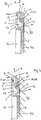
Bei dem Profil
Die Streuscheibenabdeckung
Die Streuscheibenabdeckung
Bei dem Leuchtmittel
Die
Das Profilsystem
BezugszeichenlisteLIST OF REFERENCE NUMBERS
- 11
- Profilsystemprofile system
- 22
- Profilprofile
- 33
- LeuchtmittelLamp
- 44
- StreuscheibenabdeckungDiffuser cover
- 55
- StreuscheibenabdeckungDiffuser cover
- 66
- Befestigungsschenkelfastening leg
- 7 7
- DurchgangslochThrough Hole
- 88th
- Rückseiteback
- 99
- Profilabschnittprofile section
- 1010
- Begrenzungsschenkel limiting leg
- 1111
- Seitenschenkel side leg
- 1212
- Seitenschenkel side leg
- 1313
- Vorsprung head Start
- 1414
- Vorsprung head Start
- 1515
- Aussparung recess
- 1616
- Basisabschnitt base section
- 1717
- Seitenabschnitt side portion
- 1818
- Seitenabschnitt side portion
- 1919
- Klebestreifen tape
- 2020
- Vorsprung head Start
- 2121
- Nutförmige Aussparung Grooved recess
- 2222
- Nutförmige Aussparung Grooved recess
- 2323
- Kanal channel
- 2424
- Basisabschnitt base section
- 2525
- Seitenabschnitt side portion
- 2626
- Seitenabschnitt side portion
- 2727
- Vorsprung head Start
- 2828
- Nutförmige Aussparung Grooved recess
- 2929
- Nutförmige Aussparung Grooved recess
- 3030
- Zurückspringender Bereich Receding area
- 3131
- Vorspringender Bereich Projecting area
- 3232
- Fliesenkleber tile glue
- 3333
- Untergrund underground
- 3434
- Fliese tile
- AA
- Pfeilarrow
- BB
- Pfeilarrow
ZITATE ENTHALTEN IN DER BESCHREIBUNG QUOTES INCLUDE IN THE DESCRIPTION
Diese Liste der vom Anmelder aufgeführten Dokumente wurde automatisiert erzeugt und ist ausschließlich zur besseren Information des Lesers aufgenommen. Die Liste ist nicht Bestandteil der deutschen Patent- bzw. Gebrauchsmusteranmeldung. Das DPMA übernimmt keinerlei Haftung für etwaige Fehler oder Auslassungen.This list of the documents listed by the applicant has been generated automatically and is included solely for the better information of the reader. The list is not part of the German patent or utility model application. The DPMA assumes no liability for any errors or omissions.
Zitierte PatentliteraturCited patent literature
- DE 29709378 U[0002]DE 29709378 U[0002]
Claims (15)
Translated fromGermanPriority Applications (5)
| Application Number | Priority Date | Filing Date | Title |
|---|---|---|---|
| DE202013100144.9UDE202013100144U1 (en) | 2013-01-11 | 2013-01-11 | lighting system |
| EP14150414.2AEP2754776B1 (en) | 2013-01-11 | 2014-01-08 | Profile system for bordering cladding panels |
| ES14150414.2TES2663787T3 (en) | 2013-01-11 | 2014-01-08 | Profile system to delimit the lining of a plate |
| CA2839666ACA2839666C (en) | 2013-01-11 | 2014-01-09 | Profile system |
| US14/152,030US9085903B2 (en) | 2013-01-11 | 2014-01-10 | Profile system |
Applications Claiming Priority (1)
| Application Number | Priority Date | Filing Date | Title |
|---|---|---|---|
| DE202013100144.9UDE202013100144U1 (en) | 2013-01-11 | 2013-01-11 | lighting system |
Publications (1)
| Publication Number | Publication Date |
|---|---|
| DE202013100144U1true DE202013100144U1 (en) | 2014-04-15 |
Family
ID=49886851
Family Applications (1)
| Application Number | Title | Priority Date | Filing Date |
|---|---|---|---|
| DE202013100144.9UExpired - LifetimeDE202013100144U1 (en) | 2013-01-11 | 2013-01-11 | lighting system |
Country Status (5)
| Country | Link |
|---|---|
| US (1) | US9085903B2 (en) |
| EP (1) | EP2754776B1 (en) |
| CA (1) | CA2839666C (en) |
| DE (1) | DE202013100144U1 (en) |
| ES (1) | ES2663787T3 (en) |
Cited By (2)
| Publication number | Priority date | Publication date | Assignee | Title |
|---|---|---|---|---|
| DE102016011767A1 (en)* | 2016-09-30 | 2018-04-19 | Schock Profilsysteme Gmbh & Co. Kg | Molding |
| CN108141018A (en)* | 2015-06-30 | 2018-06-08 | 杰里米·P·霍夫曼 | System and method for securing power and communication cables and related hardware within ceiling wires |
Families Citing this family (6)
| Publication number | Priority date | Publication date | Assignee | Title |
|---|---|---|---|---|
| US10676978B2 (en)* | 2017-06-16 | 2020-06-09 | Todd A. Hohwart | Actuatable sliding panel assembly; retrofit kit and method for retrofitting a sliding panel for mechanically assisted movement between open and closed positions |
| TWD199376S (en)* | 2018-02-28 | 2019-08-21 | 紐西蘭商金家控股有限公司 | Building extrusion |
| US11287123B2 (en) | 2019-07-17 | 2022-03-29 | Schluter Systems L.P. | Watertight LED arrangement |
| DE102018117343A1 (en) | 2018-07-18 | 2020-01-23 | Schlüter-Systems Kg | Waterproof LED arrangement |
| DE202019103806U1 (en) | 2019-07-10 | 2019-08-06 | Schlüter-Systems Kg | Installation kit for the production of a niche |
| WO2021175765A1 (en)* | 2020-03-06 | 2021-09-10 | Signify Holding B.V. | A lighting device arranged to be attached to a mounting surface of an object |
Citations (1)
| Publication number | Priority date | Publication date | Assignee | Title |
|---|---|---|---|---|
| DE29709378U1 (en) | 1997-05-28 | 1997-07-31 | Schlüter-Systems GmbH, 58640 Iserlohn | Profile to be glued on the subsurface to complete installed ceramic plates or the like. |
Family Cites Families (39)
| Publication number | Priority date | Publication date | Assignee | Title |
|---|---|---|---|---|
| US1984355A (en) | 1931-10-30 | 1934-12-18 | Bryant Electric Co | Electric wiring system |
| US2947093A (en)* | 1957-08-21 | 1960-08-02 | Albert M Masters | Mounting construction and the combination thereof with a board |
| US3667177A (en)* | 1970-05-08 | 1972-06-06 | Elmer G Biela | Molding joints and universal molding members therefor |
| GB8807758D0 (en)* | 1988-03-31 | 1988-05-05 | Consumerville Ltd | Decorative lighting system |
| US5140506A (en) | 1989-02-23 | 1992-08-18 | Robern, Inc. | Bath cabinet and light fixture mounting and finishing apparatus |
| US5165780A (en) | 1989-02-23 | 1992-11-24 | Robern, Inc. | Bath cabinet and light fixture mounting and finishing apparatus |
| DE4141601C1 (en)* | 1991-12-17 | 1992-12-17 | Schlueter Systems Gmbh, 5860 Iserlohn, De | |
| US5336849A (en)* | 1992-01-17 | 1994-08-09 | The Wiremold Company | Raceway assembly for power and communications conductors |
| US5514834A (en) | 1993-10-01 | 1996-05-07 | Zimmerman; Harry I. | Flanged conduit and insulation for electric wires and method of use |
| US5732747A (en)* | 1997-01-21 | 1998-03-31 | Icm Corporation | Cove molding cover for electrical cables |
| DE29711074U1 (en) | 1997-06-25 | 1998-07-23 | A + W Bad design GmbH, 33335 Gütersloh | Cupboard, especially bathroom cupboard |
| DE29711606U1 (en)* | 1997-07-02 | 1997-10-02 | Herm. Friedr. Künne GmbH & Co., 58513 Lüdenscheid | Bridging arrangement |
| US6401418B1 (en)* | 1999-11-12 | 2002-06-11 | Sierra Technology, Llc | Coving method for tubs and showers |
| SE517353C2 (en)* | 1999-12-13 | 2002-05-28 | Perstorp Flooring Ab | Transition strip on floors intended to be placed at the end of a floor unit or between two floor units |
| FR2803367B1 (en) | 2000-01-05 | 2002-03-08 | L D | LIGHT BOARD |
| US6591575B2 (en)* | 2000-04-25 | 2003-07-15 | Robert Benedettini | Tile edging strip |
| US6504098B2 (en)* | 2001-04-17 | 2003-01-07 | James D. Seamans | Architectural moldings for protecting, concealing and accessing indoor wiring and cables |
| DE20111376U1 (en)* | 2001-07-09 | 2001-08-30 | Arturo Salice S.P.A., Novedrate, Como | Extruded profile with cover strip |
| FR2827434B1 (en) | 2001-07-13 | 2003-12-12 | Legrand Sa | ACCESSORY FOR CHANNEL WITH DIFFERENT HEIGHTS |
| US6990776B2 (en)* | 2002-01-25 | 2006-01-31 | Berman Oscar G | Wall covering with holder |
| JP2005530066A (en)* | 2002-06-14 | 2005-10-06 | アルトロ・リミテッド | Improved finish for flooring |
| DE20212950U1 (en) | 2002-08-23 | 2003-12-24 | Ott, Niko | Mounting rail for reversible attachment of objects to wall surface, e.g. to bathtub, has protruding covering flange parallel to its wall attachment surface for covering tile edge |
| US6798314B2 (en) | 2002-12-26 | 2004-09-28 | Intel Corporation | Transmit/receive combiner using shunt admittance elements for isolation |
| US7255454B2 (en)* | 2004-06-24 | 2007-08-14 | Peterson John W | Emergency lighting system and method |
| ITPC20040036A1 (en)* | 2004-09-27 | 2004-12-27 | Profili Italia Spa | EXTRUDED PROFILE FOR THE CONSTRUCTION OF THE BALCONY TERRACES OR SIMILAR TILES WITH DIFFERENT THICKNESS FLOORING |
| ITMI20050647A1 (en)* | 2005-04-14 | 2006-10-15 | Canalplast S P A | DUCT STRUCTURE EQUIPPED WITH AN ANTI-SLIP COVER TO CONTAIN PIPE AND SIMILAR CABLES |
| US7388163B2 (en)* | 2005-08-23 | 2008-06-17 | Panduit Corp. | Metal raceway system |
| US7793483B2 (en)* | 2006-09-18 | 2010-09-14 | Pergo AG | Ventilated floor moldings |
| DE202007011342U1 (en) | 2007-08-14 | 2007-11-15 | Fennel Gmbh & Co. Kg | Wall terminating element |
| DE102008056958A1 (en)* | 2008-10-31 | 2010-05-06 | Marquardt Keramik Gmbh | Light system for installation in e.g. tile cladding, has profile rail limiting semi-opened light channel, and LED light strip inserted into light channel, where light-transmissive covering strip covers light channel |
| DE202009001162U1 (en) | 2009-01-30 | 2009-04-09 | Thomas Kofferath Fliesenlegerbedarf Gmbh | hollow rail |
| US8197105B2 (en)* | 2009-08-13 | 2012-06-12 | Intematix Corporation | LED-based lamps |
| DE202010001352U1 (en)* | 2010-01-25 | 2011-06-09 | Schlüter-Systems KG, 58640 | Trim for showers |
| DE202010005347U1 (en) | 2010-04-30 | 2010-08-12 | hülsta-werke Hüls GmbH & Co KG | Edge-lit glass shelf |
| WO2011151272A1 (en) | 2010-05-30 | 2011-12-08 | Stephan Gunst | Light fitting for led strips |
| DE102010060218A1 (en) | 2010-10-28 | 2014-01-16 | Hella Kgaa Hueck & Co. | Illumination arrangement for illuminating a worktop |
| DE202011001926U1 (en)* | 2011-01-25 | 2012-04-30 | Hohnen & Mouwens GmbH | Closing device as a boundary of a front side of a floor, wall or ceiling covering |
| AT511325B1 (en) | 2011-06-16 | 2012-11-15 | Karl Pedross Ag | PROFILE SYSTEM |
| DE202011104306U1 (en) | 2011-08-12 | 2011-10-20 | EVN Elektro-Vertrieb-Nürnberg GmbH | Aluminum profile rail system for LED stripes and LED light |
- 2013
- 2013-01-11DEDE202013100144.9Upatent/DE202013100144U1/ennot_activeExpired - Lifetime
- 2014
- 2014-01-08ESES14150414.2Tpatent/ES2663787T3/enactiveActive
- 2014-01-08EPEP14150414.2Apatent/EP2754776B1/enactiveActive
- 2014-01-09CACA2839666Apatent/CA2839666C/enactiveActive
- 2014-01-10USUS14/152,030patent/US9085903B2/enactiveActive
Patent Citations (1)
| Publication number | Priority date | Publication date | Assignee | Title |
|---|---|---|---|---|
| DE29709378U1 (en) | 1997-05-28 | 1997-07-31 | Schlüter-Systems GmbH, 58640 Iserlohn | Profile to be glued on the subsurface to complete installed ceramic plates or the like. |
Cited By (3)
| Publication number | Priority date | Publication date | Assignee | Title |
|---|---|---|---|---|
| CN108141018A (en)* | 2015-06-30 | 2018-06-08 | 杰里米·P·霍夫曼 | System and method for securing power and communication cables and related hardware within ceiling wires |
| CN108141018B (en)* | 2015-06-30 | 2020-10-13 | 杰里米·P·霍夫曼 | System and method for securing power and communication cables and related hardware within crown molding |
| DE102016011767A1 (en)* | 2016-09-30 | 2018-04-19 | Schock Profilsysteme Gmbh & Co. Kg | Molding |
Also Published As
| Publication number | Publication date |
|---|---|
| ES2663787T3 (en) | 2018-04-17 |
| EP2754776B1 (en) | 2018-01-31 |
| EP2754776A2 (en) | 2014-07-16 |
| CA2839666C (en) | 2021-02-16 |
| US9085903B2 (en) | 2015-07-21 |
| CA2839666A1 (en) | 2014-07-11 |
| EP2754776A3 (en) | 2015-07-08 |
| US20140196384A1 (en) | 2014-07-17 |
Similar Documents
| Publication | Publication Date | Title |
|---|---|---|
| EP2754776B1 (en) | Profile system for bordering cladding panels | |
| EP2754952B1 (en) | Illumination system | |
| EP2754953B1 (en) | Illumination system | |
| EP2754775B1 (en) | Illuminated Profile System for use with cladding panels | |
| EP2754955B1 (en) | Illumination system | |
| AT15671U1 (en) | Flexible luminaire arrangement for curved coves | |
| DE202010007926U1 (en) | Wall end strip with integrated light source | |
| DE202012002594U1 (en) | Lighting profile arrangement | |
| DE202011051236U1 (en) | Suitable for indirect lighting Wandabschlussleiste | |
| DE102015113787A1 (en) | light unit | |
| DE102014104448B4 (en) | Luminaire with a light guide for generating glare-free, partial-surface light | |
| EP2722461A2 (en) | Tile rail for an LED wall illumination | |
| DE102012207540A1 (en) | lamp | |
| DE102014110449B4 (en) | Lighting system for a staircase assembly and method for mounting such a lighting system | |
| EP2891755A1 (en) | Baseboard | |
| DE202013005155U1 (en) | lightbox | |
| DE202013104478U1 (en) | Profile, fastening device and kit | |
| DE102011057153A1 (en) | Skirting board for displaying emergency exit in public buildings, particularly for hotels, guesthouses or hostels, has phosphorescence element arranged in extension direction of recesses and assigned in viewing side of skirting board | |
| DE4014548A1 (en) | Illuminated ceramic tile for stairway - has formed slot to receive strip lighting element | |
| DE202010000363U1 (en) | Lighting for the base area of a piece of furniture | |
| DE202017102839U1 (en) | Three-dimensional wall or ceiling paneling | |
| DE102005036902B3 (en) | Lighting arrangement for illuminating an inside or outside of a building comprises a flexible tongue directly molded to an edge region of an outer surface of a housing | |
| DE7928451U1 (en) | KIT WITH CLAMPING DEVICE AND STRIPS FOR A FAIRING STRUCTURE | |
| DE102018115047B4 (en) | curtain rail | |
| AT519736B1 (en) | Multi-surface building overvoltage facility |
Legal Events
| Date | Code | Title | Description |
|---|---|---|---|
| R207 | Utility model specification | Effective date:20140522 | |
| R150 | Utility model maintained after payment of first maintenance fee after three years | ||
| R151 | Utility model maintained after payment of second maintenance fee after six years | ||
| R152 | Utility model maintained after payment of third maintenance fee after eight years | ||
| R071 | Expiry of right |