DE202013009965U1 - Electric drive system - Google Patents
Electric drive systemDownload PDFInfo
- Publication number
- DE202013009965U1 DE202013009965U1DE202013009965.8UDE202013009965UDE202013009965U1DE 202013009965 U1DE202013009965 U1DE 202013009965U1DE 202013009965 UDE202013009965 UDE 202013009965UDE 202013009965 U1DE202013009965 U1DE 202013009965U1
- Authority
- DE
- Germany
- Prior art keywords
- drive system
- drive
- user interface
- control unit
- bed
- Prior art date
- Legal status (The legal status is an assumption and is not a legal conclusion. Google has not performed a legal analysis and makes no representation as to the accuracy of the status listed.)
- Expired - Lifetime
Links
- 230000000474nursing effectEffects0.000claimsdescription15
- 238000012423maintenanceMethods0.000claimsdescription4
- 238000002680cardiopulmonary resuscitationMethods0.000claimsdescription3
- 238000010586diagramMethods0.000description2
- 230000002441reversible effectEffects0.000description2
- BUHVIAUBTBOHAG-FOYDDCNASA-N(2r,3r,4s,5r)-2-[6-[[2-(3,5-dimethoxyphenyl)-2-(2-methylphenyl)ethyl]amino]purin-9-yl]-5-(hydroxymethyl)oxolane-3,4-diolChemical compoundCOC1=CC(OC)=CC(C(CNC=2C=3N=CN(C=3N=CN=2)[C@H]2[C@@H]([C@H](O)[C@@H](CO)O2)O)C=2C(=CC=CC=2)C)=C1BUHVIAUBTBOHAG-FOYDDCNASA-N0.000description1
- 230000005540biological transmissionEffects0.000description1
- 210000003027ear innerAnatomy0.000description1
- 239000004744fabricSubstances0.000description1
- 208000005346nocturnal enuresisDiseases0.000description1
- 239000007787solidSubstances0.000description1
Images

Classifications
- A—HUMAN NECESSITIES
- A61—MEDICAL OR VETERINARY SCIENCE; HYGIENE
- A61G—TRANSPORT, PERSONAL CONVEYANCES, OR ACCOMMODATION SPECIALLY ADAPTED FOR PATIENTS OR DISABLED PERSONS; OPERATING TABLES OR CHAIRS; CHAIRS FOR DENTISTRY; FUNERAL DEVICES
- A61G7/00—Beds specially adapted for nursing; Devices for lifting patients or disabled persons
- A61G7/002—Beds specially adapted for nursing; Devices for lifting patients or disabled persons having adjustable mattress frame
- A61G7/018—Control or drive mechanisms
- A—HUMAN NECESSITIES
- A61—MEDICAL OR VETERINARY SCIENCE; HYGIENE
- A61G—TRANSPORT, PERSONAL CONVEYANCES, OR ACCOMMODATION SPECIALLY ADAPTED FOR PATIENTS OR DISABLED PERSONS; OPERATING TABLES OR CHAIRS; CHAIRS FOR DENTISTRY; FUNERAL DEVICES
- A61G2203/00—General characteristics of devices
- A61G2203/10—General characteristics of devices characterised by specific control means, e.g. for adjustment or steering
- A61G2203/16—Touchpads
- A—HUMAN NECESSITIES
- A61—MEDICAL OR VETERINARY SCIENCE; HYGIENE
- A61G—TRANSPORT, PERSONAL CONVEYANCES, OR ACCOMMODATION SPECIALLY ADAPTED FOR PATIENTS OR DISABLED PERSONS; OPERATING TABLES OR CHAIRS; CHAIRS FOR DENTISTRY; FUNERAL DEVICES
- A61G7/00—Beds specially adapted for nursing; Devices for lifting patients or disabled persons
- A61G7/002—Beds specially adapted for nursing; Devices for lifting patients or disabled persons having adjustable mattress frame
- A61G7/012—Beds specially adapted for nursing; Devices for lifting patients or disabled persons having adjustable mattress frame raising or lowering of the whole mattress frame
- A—HUMAN NECESSITIES
- A61—MEDICAL OR VETERINARY SCIENCE; HYGIENE
- A61G—TRANSPORT, PERSONAL CONVEYANCES, OR ACCOMMODATION SPECIALLY ADAPTED FOR PATIENTS OR DISABLED PERSONS; OPERATING TABLES OR CHAIRS; CHAIRS FOR DENTISTRY; FUNERAL DEVICES
- A61G7/00—Beds specially adapted for nursing; Devices for lifting patients or disabled persons
- A61G7/002—Beds specially adapted for nursing; Devices for lifting patients or disabled persons having adjustable mattress frame
- A61G7/015—Beds specially adapted for nursing; Devices for lifting patients or disabled persons having adjustable mattress frame divided into different adjustable sections, e.g. for Gatch position
Landscapes
- Health & Medical Sciences (AREA)
- Nursing (AREA)
- Life Sciences & Earth Sciences (AREA)
- Animal Behavior & Ethology (AREA)
- General Health & Medical Sciences (AREA)
- Public Health (AREA)
- Veterinary Medicine (AREA)
- Invalid Beds And Related Equipment (AREA)
Abstract
Translated fromGermanDescription
Translated fromGermanDie Erfindung betrifft eine Bedieneinheit eines Antriebssystems. Die Erfindung betrifft weiterhin ein Krankenhaus- und Pflegebett, das das Antriebssystem umfasst.The invention relates to an operating unit of a drive system. The invention further relates to a hospital and nursing bed comprising the drive system.
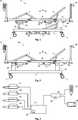
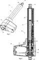
Das Antriebssystem ist Erfindungsgemäß von einer Art, die zum Justieren eines Krankenhaus- oder Pflegebetts verwendet werden kann. In dieser Art Bett wird die Matratze von einer durch eine Rücken- und eine Beinsektion verstellbare Tragefläche getragen, die in einem Bettrahmen montiert ist und mithilfe von Linearantrieben, die Teil des Antriebssystems sind, angehoben und abgesenkt werden kann. Außerdem können auch die Rücken- und die Beinsektion mithilfe von Linearantrieben verstellt werden. Normalerweise wird ein Linearantriebstyp verwendet, der ein Hubrohr umfasst, beispielsweise vom Typ, der in
Es ist bekannt, für Antriebssysteme für Krankenhaus- und Pflegebetten eine oder mehrere unterschiedliche Bedieneinheiten zu verwenden. Die Bedieneinheit(en), die von der im Bett liegenden Person verwendet wird/werden, hat/haben in der Regel eine eingeschränkte Funktionsfähigkeit. Die Bedieneinheiten, die vom Pflegepersonal verwendet werden, haben hingegen eine größere Funktionsfähigkeit, mit der es beispielsweise möglich ist, bei den von den bettlägerigen Personen verwendeten Bedieneinheiten Einschränkungen einzustellen. Außerdem hat das Pflegepersonal über seine Bedieneinheit die Möglichkeit, beispielsweise eine bettlägerige Person zu wiegen oder die Konfiguration für beispielsweise einen mit dem Antriebssystem des Betts verbundenen Matrazenschutz einzustellen.It is known to use one or more different operating units for drive systems for hospital and nursing beds. The control unit (s) used by the person in bed generally has limited functionality. On the other hand, the operating units used by the nursing staff have greater functionality, for example, with which it is possible to set restrictions on the operating units used by the bedridden persons. In addition, the nursing staff on his control unit has the ability to weigh, for example, a bedridden person or set the configuration for example, connected to the drive system of the bed mattress protection.
Die Bedieneinheiten umfassen in der Regel eine Reihe von Tasten und in einigen Fällen ein Display, auf dem sich die Verwendung des Betts oder die durchgeführten Einstellungen anzeigen lassen. Anderer Bedieneinheiten umfassen eine Reihe von Symbolen mit Leuchtindikatoren, die aufleuchten, wenn sie aktiv oder inaktiv sind. Wenn das Antriebssystem über zahlreiche Funktionen verfügt, haben die dazugehörigen Bedieneinheiten häufig unzweckmäßig große Abmessungen und sind damit unüberschaubar.The control panels typically include a series of buttons and, in some cases, a display showing the use of the bed or the adjustments made. Other control units include a number of icons with light indicators that light up when they are active or inactive. If the drive system has numerous functions, the associated control units are often impractically large dimensions and thus unmanageable.
Somit besteht der Wunsch, eine einfachere Bedieneinheit für ein Antriebssystem bereitzustellen, ohne die Funktionsfähigkeit des Antriebssystems für ein Krankenhaus- oder Pflegebett zu verringern.Thus, there is a desire to provide a simpler operating unit for a drive system without reducing the operability of the drive system for a hospital or nursing bed.
Diese Aufgabe wird Erfindungsgemäß durch ein elektrisches Antriebssystem gelöst, das mindestens einen elektromechanischen Linearantrieb, eine Steuerung, mindestens eine Bedieneeinheit umfasst, wobei die Bedieneinheit einen berührungsempfindlichen Bildschirm umfasst. Mit dem berührungsempfindlichen Bildschirm ist es möglich, die Funktionsfähigkeit des Antriebssystems zu erhöhen, da dem Benutzer nicht alle Funktionen gleichzeitig präsentiert werden müssen. Der Benutzer kann somit an den Einzelheiten der Einstellung arbeiten und gleichzeitig den vollständigen Überblick bewahren.This object is achieved according to the invention by an electric drive system which comprises at least one electromechanical linear drive, a controller, at least one operating unit, wherein the operating unit comprises a touch-sensitive screen. The touch-sensitive screen makes it possible to increase the operability of the drive system, since not all functions must be presented to the user at the same time. The user can thus work on the details of the setting and at the same time keep the complete overview.
In einer weiteren Erfindungsgemäßen Ausführungsform umfasst das elektrische Antriebssystem mindestens eine Taste. Auf diese Weise kann der Benutzer ohne Verwendung des berührungsempfindlichen Bildschirms unmittelbar Zugriff auf bestimmte Funktionen erhalten. Demgemäß kann die Taste Erfindungsgemäß eine Ein-/Aus-Funktion umfassen. Diese Ein-/Aus-Funktion kann außerdem als Start-Taste für die Benutzeroberfläche des berührungsempfindlichen Bildschirms verwendet werden.In a further embodiment according to the invention, the electric drive system comprises at least one key. In this way, the user can immediately access certain functions without using the touch-sensitive screen. Accordingly, the key according to the invention may include an on / off function. This on / off function can also be used as the start button for the touch screen interface.
In einer anderen Ausführungsform kann die Taste auf der Bedieneinheit eine Funktion zur Verwendung in Verbindung mit einer Herz-Lungen-Wiederbelebung (CPR: cardiopulmonary resuscitation) umfassen.In another embodiment, the button on the control unit may include a function for use in conjunction with cardiopulmonary resuscitation (CPR).
In einer Ausführungsform des Antriebssystems umfasst die Bedieneinheit einen Identifikationssensor zur Identifizierung eines Benutzers des elektrischen Antriebssystems. Der Identifikationssensor kann als RFID-Leser ausgebildet sein, der ein RFID-Tag liest.In one embodiment of the drive system, the operating unit comprises an identification sensor for identifying a user of the electric drive system. The identification sensor may be designed as an RFID reader that reads an RFID tag.
In einer weiteren Ausführungsform des elektrischen Antriebssystems umfasst der berührungsempfindliche Bildschirm drei Benutzeroberflächen: eine Patienten-Benutzeroberfläche, eine Pflege-Benutzeroberfläche und eine Service-Benutzeroberfläche. Dadurch wird sichergestellt, dass der jeweilige Benutzer immer die Benutzeroberfläche mit dem für ihn relevanten Inhalt verwendet. Der Zugriff auf die verschiedenen Benutzeroberflächen kann vorteilhaft mithilfe des beschriebenen Identifikationssensors erfolgen.In another embodiment of the electric drive system, the touch screen includes three user interfaces: a patient user interface, a care user interface, and a service user interface. This ensures that the respective User always uses the UI with content relevant to it. The access to the various user interfaces can advantageously take place with the help of the described identification sensor.
Die Erfindung betrifft außerdem ein Krankenhaus- oder Pflegebett, umfassend ein Antriebssystem gemäß den obigen Ausführungen.The invention also relates to a hospital or nursing bed, comprising a drive system according to the above statements.
Nachstehend ist ein Erfindungsgemäßes Ausführungsbeispiel des Antriebssystems unter Bezugnahme auf die beiliegende Zeichnung ausführlich beschrieben. Es zeigen:Hereinafter, an embodiment of the drive system according to the invention will be described in detail with reference to the accompanying drawings. Show it:
An die Steuereinheit
Der Linearantrieb
Das Antriebssystem kann an eine Rufanlage oder ein Alarmsystem angeschlossen sein, die bzw. das von dem jeweiligen Krankenhaus oder Pflegeheim genutzt wird. Diese Verbindung mit dem Antriebssystem kann abhängig von der Rufanlage oder dem Alarmsystem des jeweiligen Krankenhauses oder Pflegeheims auf verschiedene Weise erfolgen. So kann die Verbindung entweder kabelgebunden und/oder drahtlos sein. Ist die Verbindung kabelgebunden, kann dies beispielsweise über ein Kabel erfolgen, das von der Steuereinheit
Die Steuereinheit
Es sei hinzugefügt, dass die Erfindung ebenfalls bei sogenannten Doppelantrieben verwendbar ist, die zwei Spindeleinheiten und eine Steuereinheit in demselben Gehäuse verwenden. Diese Art ist genauer in
ZITATE ENTHALTEN IN DER BESCHREIBUNG QUOTES INCLUDE IN THE DESCRIPTION
Diese Liste der vom Anmelder aufgeführten Dokumente wurde automatisiert erzeugt und ist ausschließlich zur besseren Information des Lesers aufgenommen. Die Liste ist nicht Bestandteil der deutschen Patent- bzw. Gebrauchsmusteranmeldung. Das DPMA übernimmt keinerlei Haftung für etwaige Fehler oder Auslassungen.This list of the documents listed by the applicant has been generated automatically and is included solely for the better information of the reader. The list is not part of the German patent or utility model application. The DPMA assumes no liability for any errors or omissions.
Zitierte PatentliteraturCited patent literature
- WO 02/29284 A1[0002]WO 02/29284 A1[0002]
- WO 2007/093181 A1[0029]WO 2007/093181 A1[0029]
Claims (9)
Translated fromGermanApplications Claiming Priority (2)
| Application Number | Priority Date | Filing Date | Title |
|---|---|---|---|
| DK201200710 | 2012-11-13 | ||
| DKPA201200710 | 2012-11-13 |
Publications (1)
| Publication Number | Publication Date |
|---|---|
| DE202013009965U1true DE202013009965U1 (en) | 2014-02-17 |
Family
ID=50235691
Family Applications (1)
| Application Number | Title | Priority Date | Filing Date |
|---|---|---|---|
| DE202013009965.8UExpired - LifetimeDE202013009965U1 (en) | 2012-11-13 | 2013-11-06 | Electric drive system |
Country Status (1)
| Country | Link |
|---|---|
| DE (1) | DE202013009965U1 (en) |
Cited By (1)
| Publication number | Priority date | Publication date | Assignee | Title |
|---|---|---|---|---|
| DE102017122942A1 (en)* | 2017-10-04 | 2019-04-04 | Prof. Dr. Fischer AG | relaxation lounger |
Citations (2)
| Publication number | Priority date | Publication date | Assignee | Title |
|---|---|---|---|---|
| WO2002029284A1 (en) | 2000-10-03 | 2002-04-11 | Linak A/S | A linear actuator |
| WO2007093181A1 (en) | 2006-02-18 | 2007-08-23 | Linak A/S | Linear actuator device |
- 2013
- 2013-11-06DEDE202013009965.8Upatent/DE202013009965U1/ennot_activeExpired - Lifetime
Patent Citations (2)
| Publication number | Priority date | Publication date | Assignee | Title |
|---|---|---|---|---|
| WO2002029284A1 (en) | 2000-10-03 | 2002-04-11 | Linak A/S | A linear actuator |
| WO2007093181A1 (en) | 2006-02-18 | 2007-08-23 | Linak A/S | Linear actuator device |
Cited By (1)
| Publication number | Priority date | Publication date | Assignee | Title |
|---|---|---|---|---|
| DE102017122942A1 (en)* | 2017-10-04 | 2019-04-04 | Prof. Dr. Fischer AG | relaxation lounger |
Similar Documents
| Publication | Publication Date | Title |
|---|---|---|
| DE212012000026U1 (en) | Electric drive system | |
| DE3036217C2 (en) | Remote-controlled medical device | |
| DE202011051662U1 (en) | Electromotive furniture drive | |
| EP2780767B1 (en) | Arrangement with an electromotive furniture drive and a data device; method for establishing a communication connection between the electromotive furniture drive and the data device; and a corresponding furniture drive | |
| DE102014202654A1 (en) | Mobile X-ray generating device | |
| DE102012103029A1 (en) | Modular intensive therapy device | |
| EP2991607A1 (en) | Operating table and method for controlling an operating table | |
| DE102007013354A1 (en) | Care bed with electrical emergency lowering | |
| DE112016002543T5 (en) | Patient support devices with dynamic control panels | |
| DE212012000028U1 (en) | Electric drive system | |
| WO2009063404A1 (en) | Respirator and/or anesthetic device | |
| DE112004002960T5 (en) | Passenger interface with disinfection feature for lifts | |
| DE102012006192A1 (en) | Thermotherapy device | |
| WO2007057420A1 (en) | Electrical device arrangement, in particular for an item of furniture, having a bus device and bus subscribers, and method for controlling such an electrical device arrangement | |
| DE202013009965U1 (en) | Electric drive system | |
| EP3433776B1 (en) | Remote processing of messages for a dialysis apparatus | |
| DE60029101T2 (en) | Bed and handset for controlling adjustment movements | |
| DE19929907A1 (en) | Controller for reclining support, especially operating table, has control electronics with microcontroller with associated driver stage(s) for drive, control panel program and data memory | |
| DE202019005356U1 (en) | Actuator system | |
| EP2640334A1 (en) | Electric motor furniture drive | |
| EP3895678B1 (en) | Device and method for the networked transport of patients or mobility-impaired persons | |
| EP4039161A1 (en) | Environment cleaning system | |
| DE202008017828U1 (en) | Drive system for adjustable furniture | |
| DE102016005061A1 (en) | Device for supporting technical documentation and troubleshooting technical installations | |
| DE10303717A1 (en) | Patient monitor with integrated ultrasound modules |
Legal Events
| Date | Code | Title | Description |
|---|---|---|---|
| R207 | Utility model specification | Effective date:20140327 | |
| R150 | Utility model maintained after payment of first maintenance fee after three years | ||
| R157 | Lapse of ip right after 6 years |