DE202012007216U1 - contact element - Google Patents
contact elementDownload PDFInfo
- Publication number
- DE202012007216U1 DE202012007216U1DE202012007216UDE202012007216UDE202012007216U1DE 202012007216 U1DE202012007216 U1DE 202012007216U1DE 202012007216 UDE202012007216 UDE 202012007216UDE 202012007216 UDE202012007216 UDE 202012007216UDE 202012007216 U1DE202012007216 U1DE 202012007216U1
- Authority
- DE
- Germany
- Prior art keywords
- contact
- ring
- outer conductor
- circuit board
- contact element
- Prior art date
- Legal status (The legal status is an assumption and is not a legal conclusion. Google has not performed a legal analysis and makes no representation as to the accuracy of the status listed.)
- Expired - Lifetime
Links
- 239000004020conductorSubstances0.000claimsabstractdescription51
- 239000002184metalSubstances0.000claimsdescription8
- 229910052751metalInorganic materials0.000claimsdescription8
- 239000000835fiberSubstances0.000description6
- 238000005476solderingMethods0.000description4
- 230000005540biological transmissionEffects0.000description3
- 238000009413insulationMethods0.000description3
- 239000000463materialSubstances0.000description3
- RYGMFSIKBFXOCR-UHFFFAOYSA-NCopperChemical compound[Cu]RYGMFSIKBFXOCR-UHFFFAOYSA-N0.000description2
- 229910000831SteelInorganic materials0.000description2
- 229910052802copperInorganic materials0.000description2
- 239000010949copperSubstances0.000description2
- 230000001419dependent effectEffects0.000description2
- 230000005489elastic deformationEffects0.000description2
- 230000010354integrationEffects0.000description2
- 239000007769metal materialSubstances0.000description2
- 239000010959steelSubstances0.000description2
- NMWSKOLWZZWHPL-UHFFFAOYSA-N3-chlorobiphenylChemical compoundClC1=CC=CC(C=2C=CC=CC=2)=C1NMWSKOLWZZWHPL-UHFFFAOYSA-N0.000description1
- 241000530268Lycaena heteroneaSpecies0.000description1
- 229920000914Metallic fiberPolymers0.000description1
- 101001082832Saccharomyces cerevisiae (strain ATCC 204508 / S288c) Pyruvate carboxylase 2Proteins0.000description1
- 230000003247decreasing effectEffects0.000description1
- 239000012777electrically insulating materialSubstances0.000description1
- 210000003746featherAnatomy0.000description1
- 238000004519manufacturing processMethods0.000description1
- 229910000679solderInorganic materials0.000description1
- 238000003466weldingMethods0.000description1
Images


Classifications
- H—ELECTRICITY
- H01—ELECTRIC ELEMENTS
- H01R—ELECTRICALLY-CONDUCTIVE CONNECTIONS; STRUCTURAL ASSOCIATIONS OF A PLURALITY OF MUTUALLY-INSULATED ELECTRICAL CONNECTING ELEMENTS; COUPLING DEVICES; CURRENT COLLECTORS
- H01R24/00—Two-part coupling devices, or either of their cooperating parts, characterised by their overall structure
- H01R24/38—Two-part coupling devices, or either of their cooperating parts, characterised by their overall structure having concentrically or coaxially arranged contacts
- H01R24/40—Two-part coupling devices, or either of their cooperating parts, characterised by their overall structure having concentrically or coaxially arranged contacts specially adapted for high frequency
- H—ELECTRICITY
- H01—ELECTRIC ELEMENTS
- H01R—ELECTRICALLY-CONDUCTIVE CONNECTIONS; STRUCTURAL ASSOCIATIONS OF A PLURALITY OF MUTUALLY-INSULATED ELECTRICAL CONNECTING ELEMENTS; COUPLING DEVICES; CURRENT COLLECTORS
- H01R13/00—Details of coupling devices of the kinds covered by groups H01R12/70 or H01R24/00 - H01R33/00
- H01R13/02—Contact members
- H01R13/22—Contacts for co-operating by abutting
- H01R13/24—Contacts for co-operating by abutting resilient; resiliently-mounted
- H01R13/2407—Contacts for co-operating by abutting resilient; resiliently-mounted characterized by the resilient means
- H—ELECTRICITY
- H01—ELECTRIC ELEMENTS
- H01R—ELECTRICALLY-CONDUCTIVE CONNECTIONS; STRUCTURAL ASSOCIATIONS OF A PLURALITY OF MUTUALLY-INSULATED ELECTRICAL CONNECTING ELEMENTS; COUPLING DEVICES; CURRENT COLLECTORS
- H01R24/00—Two-part coupling devices, or either of their cooperating parts, characterised by their overall structure
- H01R24/38—Two-part coupling devices, or either of their cooperating parts, characterised by their overall structure having concentrically or coaxially arranged contacts
- H01R24/40—Two-part coupling devices, or either of their cooperating parts, characterised by their overall structure having concentrically or coaxially arranged contacts specially adapted for high frequency
- H01R24/50—Two-part coupling devices, or either of their cooperating parts, characterised by their overall structure having concentrically or coaxially arranged contacts specially adapted for high frequency mounted on a PCB [Printed Circuit Board]
- H—ELECTRICITY
- H01—ELECTRIC ELEMENTS
- H01R—ELECTRICALLY-CONDUCTIVE CONNECTIONS; STRUCTURAL ASSOCIATIONS OF A PLURALITY OF MUTUALLY-INSULATED ELECTRICAL CONNECTING ELEMENTS; COUPLING DEVICES; CURRENT COLLECTORS
- H01R2103/00—Two poles
Landscapes
- Coupling Device And Connection With Printed Circuit (AREA)
- Multi-Conductor Connections (AREA)
Abstract
Translated fromGermanDescription
Translated fromGermanDie Erfindung betrifft ein Kontaktelement mit einem Außenleiter sowie einem innerhalb des Außenleiters angeordneten Innenleiter, die jeweils stirnseitig zur Kontaktierung eines Bauteils und insbesondere einer Leiterplatte vorgesehen sind.The invention relates to a contact element with an outer conductor and an inner conductor disposed within the outer conductor, which are each provided on the front side for contacting a component and in particular a printed circuit board.
Derartige Kontaktelemente können beispielsweise dazu dienen, kabelförmige (Koaxial-)Leiter an die entsprechenden Kontaktstellen einer Leiterplatte anzubinden. Ebenso können solche Kontaktelemente zum elektrisch leitenden Verbinden von zwei Leiterplatten vorgesehen sein.Such contact elements can serve, for example, to connect cable-shaped (coaxial) conductors to the corresponding contact points of a printed circuit board. Likewise, such contact elements may be provided for the electrically conductive connection of two printed circuit boards.
Wenn solche Kontaktelemente als Teil einer Übertragungsstrecke für Hochfrequenzsignale dienen, werden besondere Anforderungen an den Kontakt der Außen- und Innenleiter mit den Kontaktstellen der Leiterplatte gestellt.If such contact elements serve as part of a transmission path for high-frequency signals, special demands are placed on the contact of the outer and inner conductors with the contact points of the printed circuit board.
Der Innenleiter ist dann regelmäßig als Federkontaktstift, auch „Pogopin” genannt, ausgebildet. Ein solcher Federkontaktstift umfasst eine Hülse und einen teilweise innerhalb der Hülse beweglich geführten Bolzen mit einem Kontaktkopf. Eine sich zwischen dem Bolzen und der Hülse abstützende Schraubenfeder bewirkt eine Federbelastung des Bolzens in seine ausgefahrene Stellung. Die Federbelastung bewirkt, dass der Kontaktkopf des Bolzens auch bei toleranzbedingt unterschiedlichen Abständen des Federkontaktstifts zu der Kontaktstelle auf der Leiterplatte stets einen sicheren Kontakt mit ausreichendem Anpressdruck mit der Kontaktstelle hat. Der Kontaktkopf ist regelmäßig halbkugelförmig ausgebildet, wodurch toleranzbedingte Abweichungen von der senkrechten Ausrichtung des Federkontaktstifts zu der Kontaktstelle ausgeglichen werden, d. h. die Kontaktfläche des Kontaktkopfs ist stets im Wesentlichen gleich groß.The inner conductor is then regularly called spring contact pin, also called "Pogopin" formed. Such a spring contact pin comprises a sleeve and a bolt partially guided within the sleeve with a contact head. A coiled between the bolt and the sleeve coil spring causes a spring load of the bolt in its extended position. The spring load causes the contact head of the bolt always has a secure contact with sufficient contact pressure with the contact point even when tolerated due to different distances of the spring contact pin to the contact point on the circuit board. The contact head is regularly hemispherical in shape, which compensates for tolerance-related deviations from the vertical orientation of the spring contact pin to the contact point, d. H. the contact surface of the contact head is always substantially the same size.
Der den Innenleiter regelmäßig konzentrisch umgebende Außenleiter weist eine ringförmige Stirnfläche auf, die in vielen Fällen auch als Kontaktfläche dient. Nachteilig ist dies insbesondere bei einer toleranzbedingt nicht exakt senkrechten Ausrichtung des Außenleiters zu der Kontaktfläche der Leiterplatte. Dann führt ein seitliches Abheben der Kontaktfläche zu einem Kontakt mit der Kontaktstelle in nur noch einem vergleichsweise kleinen Abschnitt der Stirnfläche des Außenleiters. Ein derart „unkontrollierter” Kontakt ist insbesondere bei einer Nutzung der Kontaktelemente zur Übertragung von Hochfrequenzsignalen unerwünscht.The outer conductor which regularly concentrically surrounds the inner conductor has an annular end face, which in many cases also serves as a contact surface. This is disadvantageous in particular in the case of a tolerance-dependent not exactly perpendicular alignment of the outer conductor to the contact surface of the printed circuit board. Then, a lateral lifting of the contact surface leads to a contact with the contact point in only a comparatively small portion of the end face of the outer conductor. Such "uncontrolled" contact is particularly undesirable when using the contact elements for the transmission of high-frequency signals.
Ausgehend von diesem Stand der Technik lag der Erfindung die Aufgabe zugrunde, ein verbessertes gattungsgemäßes Kontaktelement anzugeben. Insbesondere sollte ein gattungsgemäßes Kontaktelement hinsichtlich des Kontakts zwischen dem Außenleiter und der dazugehörigen Kontaktstelle auf der Leiterplatte verbessert werden.Based on this prior art, the present invention seeks to provide an improved generic contact element. In particular, a generic contact element with respect to the contact between the outer conductor and the associated contact point on the circuit board should be improved.
Diese Aufgabe wird durch ein Kontaktelement gemäß dem unabhängigen Anspruch 1 gelöst. Vorteilhafte Ausgestaltungen sind Gegenstand der abhängigen Ansprüche und ergeben sich aus der nachfolgenden Beschreibung der Erfindung.This object is achieved by a contact element according to independent claim 1. Advantageous embodiments are the subject of the dependent claims and will become apparent from the following description of the invention.
Die Erfindung löst die gestellte Aufgabe, indem bei einem gattungsgemäßen Kontaktelement mit einem Außenleiter und einem (vorzugsweise koaxial) innerhalb des Außenleiters angeordneten Innenleiter, bei dem der Außenleiter an (zumindest) einer seiner längsaxialen Endflächen (zumindest) eine Kontaktstelle für einen Kontakt mit einer Kontaktstelle eines zu kontaktierenden Bauteils und insbesondere einer Leiterplatte aufweist, die Kontaktstelle federnd gelagert ist.The invention solves this problem by providing in a generic contact element with an outer conductor and a (preferably coaxially) disposed inside the outer conductor inner conductor, wherein the outer conductor at (at least) one of its longitudinal axial end faces (at least) a contact point for contact with a contact point a component to be contacted and in particular a printed circuit board, the contact point is resiliently mounted.
Dabei kann vorzugsweise vorgesehen sein, dass die Endfläche des Außenleiters von einem Kontaktring ausgebildet ist, der mit einem Gehäuse des Außenleiters verbunden ist. Dies vereinfacht die Integration der federnden Lagerung der Kontaktstelle und somit die Herstellung des erfindungsgemäßen Kontaktelements.It can preferably be provided that the end face of the outer conductor is formed by a contact ring, which is connected to a housing of the outer conductor. This simplifies the integration of the resilient mounting of the contact point and thus the production of the contact element according to the invention.
Eine Verbindung des Kontaktrings mit dem Gehäuse des Außenleiters kann auf einfache Weise dadurch erreicht werden, dass der Kontaktring randseitig zumindest abschnittsweise zwischen dem Gehäuse und einem Deckel gehalten ist. Der Deckel kann dabei auf beliebige Weise mit dem Gehäuse verbunden sein, beispielsweise kraftschlüssig (z. B. als Presspassung), formschlüssig (z. B. mittels Bajonett- oder Gewindeverbindung) und/oder stoffschlüssig (z. B. durch Verlöten oder Verschweißen).A connection of the contact ring with the housing of the outer conductor can be achieved in a simple manner that the contact ring is at least partially held edgewise between the housing and a lid. The cover may be connected to the housing in any desired manner, for example by a force fit (eg as a press fit), by a positive fit (eg by means of a bayonet or threaded connection) and / or by a material fit (eg by soldering or welding). ,
In einer Ausgestaltung kann vorgesehen sein, dass der Kontaktring als (vorzugsweise scheibenförmiger) Wellring ausgebildet ist. Ein solcher Wellring weist in Umfangsrichtung einen wellenförmigen Verlauf auf, wodurch zumindest eine, vorzugsweise mehrere Wellenberg-Wellental-Kombinationen geschaffen werden. Dann können beispielsweise die Wellenberge als Kontaktstellen für einen Kontakt mit der Kontaktstelle der Leiterplatte und die Wellentäler als Kontaktstellen, die einen Kontakt mit dem Gehäuse des Außenleiters sicherstellen, dienen. Vorzugsweise ist der Wellring aus einem metallischen Werkstoff wie z. B. Kupfer ausgebildet. Dadurch kann auf kostengünstige Weise ein elektrisch leitender Kontaktring geschaffen werden, der zudem die vorteilhaften elastischen Eigenschaften des Werkstoffs zur Integration der federnden Lagerung der Kontaktstelle ausnutzen kann.In one embodiment it can be provided that the contact ring is formed as a (preferably disk-shaped) corrugated ring. Such a corrugated ring has a wave-shaped course in the circumferential direction, as a result of which at least one, preferably several corrugation-wave trough combinations are created. Then, for example, the wave crests may serve as contact points for contact with the contact point of the printed circuit board and the wave troughs as contact points, which ensure contact with the housing of the outer conductor. Preferably, the corrugated ring is made of a metallic material such. B. copper formed. As a result, an electrically conductive contact ring can be created in a cost effective manner, which can also exploit the advantageous elastic properties of the material for the integration of the resilient mounting of the contact point.
In einer weiteren vorteilhaften Ausgestaltung können die vorzugsweise mehreren federnd gelagerten Kontaktstellen des Kontaktrings durch eine oder mehrere Federlaschen ausgebildet sein, die vorzugsweise in Richtung einer Mittelachse des Kontaktrings geneigt verlaufen. Dabei sind die Federlaschen vorzugsweise einstückig mit einem Grundkörper des Kontaktrings verbunden, wobei vorzugsweise (mindestens) eine Kontaktstelle an dem freien Ende (vorzugsweise jeder) der Federlaschen vorgesehen ist.In a further advantageous embodiment, the preferably several resilient mounted contact points of the contact ring may be formed by one or more spring tabs, which are preferably inclined in the direction of a central axis of the contact ring. The spring tabs are preferably integrally connected to a main body of the contact ring, wherein preferably (at least) one contact point at the free end (preferably each) of the spring tabs is provided.
In einer Ausführung kann vorgesehen sein, dass die Federlaschen radial nach innen verlaufend ausgebildet sind. Ebenso besteht die Möglichkeit, die Federlasche bogenförmig um die Mittelachse des Kontaktrings verlaufend auszubilden.In one embodiment it can be provided that the spring tabs are designed to extend radially inwardly. It is also possible to form the spring tab arcuately running around the central axis of the contact ring.
In einer weiterhin bevorzugten Ausführungsform des erfindungsgemäßen Kontaktelements kann vorgesehen sein, dass der Kontaktring (zumindest teilweise) aus Metallfilz ausgebildet ist. Bei Metallfilz handelt es sich um ein räumliches Gebilde aus ineinander verschlungenen Fasern, die zumindest teilweise aus elektrisch leitendem Werkstoff bestehen. Eine Elastizität des Kontaktrings ergibt sich dann aus einer elastischen Deformation der Fasern in Verbindung mit einer Relativbeweglichkeit zwischen diesen. Die Kontaktstellen eines Kontaktrings aus Metallfilz können von Abschnitten der Fasern ausgebildet werden.In a further preferred embodiment of the contact element according to the invention can be provided that the contact ring is formed (at least partially) of metal felt. Metal felt is a spatial structure of intertwined fibers, which consist at least partially of electrically conductive material. An elasticity of the contact ring then results from an elastic deformation of the fibers in conjunction with a relative mobility between them. The contact points of a metal felt contact ring may be formed by portions of the fibers.
Selbstverständlich besteht die Möglichkeit, dass ein Kontaktring des erfindungsgemäßen Kontaktelements mehrere oder alle der als bevorzugten beschriebenen Ausgestaltungen federnd gelagerter Kontaktstellen umfasst. Beispielsweise kann ein als Wellring ausgebildeter Kontaktring zusätzlich mit Federlaschen ausgebildet sein. Auch kann ein Wellring, gegebenenfalls mit zusätzlichen Federlaschen, mit einem darunter liegenden zweiten Kontaktring aus Metallfilz kombiniert sein. Ein Kontaktring des erfindungsgemäßen Kontaktelements kann somit auch einen mehrschichtigen Aufbau aufweisen.Of course, there is the possibility that a contact ring of the contact element according to the invention comprises several or all of the spring contact contact points described as preferred. For example, a trained as a corrugated ring contact ring may be additionally formed with spring tabs. Also, a corrugated ring, optionally with additional spring tabs, be combined with an underlying second contact ring made of metal felt. A contact ring of the contact element according to the invention can thus also have a multilayer structure.
Die Erfindung wird nachfolgend anhand von in den Zeichnungen dargestellten Ausführungsbeispielen näher erläutert. In den Zeichnungen zeigt:The invention will be explained in more detail with reference to embodiments shown in the drawings. In the drawings shows:
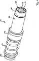
Die
Das Kontaktelement
Der Innenleiter
Eine Verbindung des Innenleiters
Die den Innenleiter
In das kabelseitige Ende des zweiten Gehäuseteils
Der zweite Gehäuseteil
Die vordere längsaxiale Endfläche des Außenleiters, die für einen Kontakt mit der Kontaktstelle der Leiterplatte
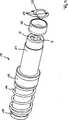
Die
Bei den Kontaktringen
Bei der Ausführungsform gemäß der
Die
Die Verbindungsvorrichtung umfasst ein Gehäuse mit einem unteren Gehäuseteil
Das obere Gehäuseteil
Dabei ist der Durchmesser der Durchgangsöffnungen nur geringfügig größer als der Außendurchmesser der kabelseitigen Enden der Kontaktelemente
Eine Verbindung zwischen dem unteren Gehäuseteil
An den Längsseiten des unteren Gehäuseteils
Wie insbesondere aus der
Das untere Gehäuseteil
Die Dimensionierung der Elemente der Verbindungsvorrichtung und der Leiterplatte
Claims (8)
Translated fromGermanPriority Applications (10)
| Application Number | Priority Date | Filing Date | Title |
|---|---|---|---|
| DE202012007216UDE202012007216U1 (en) | 2012-07-25 | 2012-07-25 | contact element |
| TW102212774UTWM468822U (en) | 2012-07-25 | 2013-07-05 | Contact element |
| HK15108877.4AHK1208561B (en) | 2012-07-25 | 2013-07-08 | Contact element |
| US14/416,660US9692191B2 (en) | 2012-07-25 | 2013-07-08 | Contact element with resiliently mounting contact points |
| CA2878970ACA2878970C (en) | 2012-07-25 | 2013-07-08 | Contact element |
| CN201380039494.8ACN104488142B (en) | 2012-07-25 | 2013-07-08 | Contact element |
| JP2015523440AJP6356125B2 (en) | 2012-07-25 | 2013-07-08 | Contact element |
| EP13734673.0AEP2878041B1 (en) | 2012-07-25 | 2013-07-08 | Contact element |
| PCT/EP2013/002008WO2014015944A1 (en) | 2012-07-25 | 2013-07-08 | Contact element |
| KR1020157001951AKR101919505B1 (en) | 2012-07-25 | 2013-07-08 | Contact element |
Applications Claiming Priority (1)
| Application Number | Priority Date | Filing Date | Title |
|---|---|---|---|
| DE202012007216UDE202012007216U1 (en) | 2012-07-25 | 2012-07-25 | contact element |
Publications (1)
| Publication Number | Publication Date |
|---|---|
| DE202012007216U1true DE202012007216U1 (en) | 2012-08-20 |
Family
ID=46875501
Family Applications (1)
| Application Number | Title | Priority Date | Filing Date |
|---|---|---|---|
| DE202012007216UExpired - LifetimeDE202012007216U1 (en) | 2012-07-25 | 2012-07-25 | contact element |
Country Status (9)
| Country | Link |
|---|---|
| US (1) | US9692191B2 (en) |
| EP (1) | EP2878041B1 (en) |
| JP (1) | JP6356125B2 (en) |
| KR (1) | KR101919505B1 (en) |
| CN (1) | CN104488142B (en) |
| CA (1) | CA2878970C (en) |
| DE (1) | DE202012007216U1 (en) |
| TW (1) | TWM468822U (en) |
| WO (1) | WO2014015944A1 (en) |
Cited By (4)
| Publication number | Priority date | Publication date | Assignee | Title |
|---|---|---|---|---|
| WO2018166737A1 (en)* | 2017-03-14 | 2018-09-20 | Rosenberger Hochfrequenztechnik Gmbh & Co. Kg | Test socket and contacting device for contacting a high frequency signal |
| CN114552257A (en)* | 2020-11-19 | 2022-05-27 | 泰连德国有限公司 | Contact Rings for Highly Dynamic Applications |
| DE102021209119A1 (en) | 2021-08-19 | 2023-02-23 | Robert Bosch Gesellschaft mit beschränkter Haftung | Drive device, pressure generator for a brake system |
| EP3406000B1 (en)* | 2016-01-18 | 2024-03-06 | Huber+Suhner Ag | Highspeed board connector |
Families Citing this family (13)
| Publication number | Priority date | Publication date | Assignee | Title |
|---|---|---|---|---|
| DE202013002575U1 (en)* | 2013-03-15 | 2013-04-17 | Rosenberger Hochfrequenztechnik Gmbh & Co. Kg | Connectors |
| US9645172B2 (en) | 2014-10-10 | 2017-05-09 | Samtec, Inc. | Cable assembly |
| CN108011264B (en)* | 2016-10-31 | 2021-08-13 | 康普技术有限责任公司 | Quick-lock coaxial connector and connector combination |
| CN109256645B (en) | 2017-07-12 | 2021-09-21 | 康普技术有限责任公司 | Quick-locking coaxial connector |
| USD823100S1 (en)* | 2017-07-19 | 2018-07-17 | Dazadi, Inc. | Tube connector |
| US10396510B1 (en)* | 2018-06-29 | 2019-08-27 | Huber + Suhner Ag | Coaxial connector with compensator |
| CN109841999B (en)* | 2019-02-22 | 2024-06-07 | 中航富士达科技股份有限公司 | Self-adaptive inter-board radio frequency connector |
| CN113767530A (en)* | 2019-03-11 | 2021-12-07 | 申泰公司 | Impedance controlled electrical contact |
| US11374346B2 (en) | 2020-06-10 | 2022-06-28 | Savannah River Nuclear Solutions, Llc | High-voltage push to mate electrical interconnect |
| CN113937580A (en)* | 2020-07-13 | 2022-01-14 | 泰科电子(上海)有限公司 | Connector with a locking member |
| US11539167B2 (en) | 2020-09-17 | 2022-12-27 | Carlisle Interconnect Technologies, Inc. | Adjustable push on connector/adaptor |
| US11502440B2 (en)* | 2020-10-23 | 2022-11-15 | Carlisle Interconnect Technologies, Inc. | Multiport connector interface system |
| CN114824960B (en)* | 2022-03-31 | 2024-10-15 | 上海精积微半导体技术有限公司 | High-frequency connection structure for high-quality signal transmission based on double floating structure |
Family Cites Families (32)
| Publication number | Priority date | Publication date | Assignee | Title |
|---|---|---|---|---|
| JPS57148886A (en)* | 1981-03-11 | 1982-09-14 | Fujitsu Ltd | Connector mounting structure |
| US4588241A (en)* | 1983-09-23 | 1986-05-13 | Probe-Rite, Inc. | Surface mating coaxial connector |
| US4850893A (en)* | 1987-05-14 | 1989-07-25 | Williams Robert A | Test probe apparatus |
| EP0348562B1 (en) | 1988-06-28 | 1993-06-16 | Trw Inc. | High-density contact area electrical connectors |
| US4892491A (en)* | 1988-12-19 | 1990-01-09 | Motorola, Inc. | Coaxial connector |
| US5982187A (en) | 1993-07-01 | 1999-11-09 | Alphatest Corporation | Resilient connector having a tubular spring |
| DE19857528C2 (en)* | 1998-12-14 | 2002-06-20 | Spinner Gmbh Elektrotech | Connector for coaxial cable with ring-corrugated outer conductor |
| US20020050388A1 (en)* | 2000-10-30 | 2002-05-02 | Simpson Jeffrey S. | Full compression coaxial cable assembly |
| DE20117997U1 (en)* | 2001-11-05 | 2002-02-14 | Rosenberger Hochfrequenztechnik GmbH & Co, 83413 Fridolfing | Spring plate for contacting a component on a circuit board and circuit arrangement with contacting spring plate |
| CN100466396C (en)* | 2003-09-17 | 2009-03-04 | 胡贝尔和茹纳股份公司 | Coaxial plug-and-socket connector |
| CN101288206A (en)* | 2005-07-02 | 2008-10-15 | 泰瑞达公司 | Connector-to-pad printed circuit board translator and method of fabrication |
| US7946853B2 (en)* | 2005-07-02 | 2011-05-24 | Teradyne, Inc. | Compliant electro-mechanical device |
| JP2009052913A (en)* | 2007-08-23 | 2009-03-12 | Yamaichi Electronics Co Ltd | Coaxial contact and coaxial multicore connector |
| DE102009020984A1 (en)* | 2008-05-13 | 2009-11-19 | Continental Teves Ag & Co. Ohg | Tolerance compensating electrical connector, in particular for motor vehicle control devices |
| US8113875B2 (en)* | 2008-09-30 | 2012-02-14 | Belden Inc. | Cable connector |
| JP5133196B2 (en) | 2008-10-10 | 2013-01-30 | モレックス インコーポレイテド | Probe connector |
| FR2937189A1 (en)* | 2008-10-13 | 2010-04-16 | Radiall Sa | COAXIAL CONNECTOR ELEMENT WITH FACILITY PRETENSION. |
| JP2010097823A (en)* | 2008-10-16 | 2010-04-30 | Tyco Electronics Japan Kk | Coaxial connector assembly |
| US7967611B2 (en)* | 2009-02-06 | 2011-06-28 | The Boeing Company | Electrical interconnect and method for electrically coupling a plurality of devices |
| US7803018B1 (en)* | 2009-03-10 | 2010-09-28 | Andrew Llc | Inner conductor end contacting coaxial connector and inner conductor adapter kit |
| US8920892B2 (en)* | 2009-03-24 | 2014-12-30 | Pactiv LLC | Container having a rolled rim, and method of making the same |
| US8573996B2 (en)* | 2009-05-22 | 2013-11-05 | Ppc Broadband, Inc. | Coaxial cable connector having electrical continuity member |
| US7887365B1 (en)* | 2009-07-22 | 2011-02-15 | Tyco Electronics Corporation | Electrical plug and jack assembly |
| WO2011146911A1 (en)* | 2010-05-21 | 2011-11-24 | Pct International, Inc. | Connector with locking mechanism and associated systems and methods |
| US8079860B1 (en)* | 2010-07-22 | 2011-12-20 | John Mezzalingua Associates, Inc. | Cable connector having threaded locking collet and nut |
| US8888526B2 (en)* | 2010-08-10 | 2014-11-18 | Corning Gilbert, Inc. | Coaxial cable connector with radio frequency interference and grounding shield |
| US8075338B1 (en)* | 2010-10-18 | 2011-12-13 | John Mezzalingua Associates, Inc. | Connector having a constant contact post |
| US8167635B1 (en)* | 2010-10-18 | 2012-05-01 | John Mezzalingua Associates, Inc. | Dielectric sealing member and method of use thereof |
| US8366481B2 (en)* | 2011-03-30 | 2013-02-05 | John Mezzalingua Associates, Inc. | Continuity maintaining biasing member |
| US8348697B2 (en)* | 2011-04-22 | 2013-01-08 | John Mezzalingua Associates, Inc. | Coaxial cable connector having slotted post member |
| US9203167B2 (en)* | 2011-05-26 | 2015-12-01 | Ppc Broadband, Inc. | Coaxial cable connector with conductive seal |
| US8491333B2 (en)* | 2011-09-09 | 2013-07-23 | Ppc Broadband, Inc. | Rotary locking push-on connector and method thereof |
- 2012
- 2012-07-25DEDE202012007216Upatent/DE202012007216U1/ennot_activeExpired - Lifetime
- 2013
- 2013-07-05TWTW102212774Upatent/TWM468822U/ennot_activeIP Right Cessation
- 2013-07-08USUS14/416,660patent/US9692191B2/enactiveActive
- 2013-07-08WOPCT/EP2013/002008patent/WO2014015944A1/enactiveApplication Filing
- 2013-07-08KRKR1020157001951Apatent/KR101919505B1/enactiveActive
- 2013-07-08CACA2878970Apatent/CA2878970C/enactiveActive
- 2013-07-08JPJP2015523440Apatent/JP6356125B2/enactiveActive
- 2013-07-08EPEP13734673.0Apatent/EP2878041B1/enactiveActive
- 2013-07-08CNCN201380039494.8Apatent/CN104488142B/enactiveActive
Cited By (4)
| Publication number | Priority date | Publication date | Assignee | Title |
|---|---|---|---|---|
| EP3406000B1 (en)* | 2016-01-18 | 2024-03-06 | Huber+Suhner Ag | Highspeed board connector |
| WO2018166737A1 (en)* | 2017-03-14 | 2018-09-20 | Rosenberger Hochfrequenztechnik Gmbh & Co. Kg | Test socket and contacting device for contacting a high frequency signal |
| CN114552257A (en)* | 2020-11-19 | 2022-05-27 | 泰连德国有限公司 | Contact Rings for Highly Dynamic Applications |
| DE102021209119A1 (en) | 2021-08-19 | 2023-02-23 | Robert Bosch Gesellschaft mit beschränkter Haftung | Drive device, pressure generator for a brake system |
Also Published As
| Publication number | Publication date |
|---|---|
| EP2878041A1 (en) | 2015-06-03 |
| CA2878970A1 (en) | 2014-01-30 |
| CA2878970C (en) | 2018-09-11 |
| US20150180182A1 (en) | 2015-06-25 |
| JP6356125B2 (en) | 2018-07-11 |
| WO2014015944A1 (en) | 2014-01-30 |
| US9692191B2 (en) | 2017-06-27 |
| KR101919505B1 (en) | 2018-11-15 |
| JP2015528192A (en) | 2015-09-24 |
| KR20150036189A (en) | 2015-04-07 |
| TWM468822U (en) | 2013-12-21 |
| CN104488142B (en) | 2017-07-04 |
| CN104488142A (en) | 2015-04-01 |
| EP2878041B1 (en) | 2019-07-03 |
| HK1208561A1 (en) | 2016-03-04 |
Similar Documents
| Publication | Publication Date | Title |
|---|---|---|
| EP2878041B1 (en) | Contact element | |
| EP2912728B1 (en) | Contact device | |
| DE202012008961U1 (en) | contact element | |
| EP3242359A1 (en) | Cable | |
| EP4014287B1 (en) | 8 + 2 way xlr pcb female connector | |
| DE102016108825B4 (en) | Clamping arrangement and connection terminal | |
| DE102013114261A1 (en) | Electronics housing of a switching device and a mountable in the electronics housing protective contact arrangement | |
| DE102019121329B4 (en) | COAXIAL CONNECTOR | |
| DE102018118224B4 (en) | Edge edge connectors and PCB assembly | |
| DE102008038589B4 (en) | Socket arrangement | |
| DE102018118405B3 (en) | Connector and plug connection with such a connector | |
| EP1671399B1 (en) | Shield connection | |
| DE202012002352U1 (en) | Arrangement of plug connector and circuit board | |
| DE4212710A1 (en) | Connection element for coaxial cable | |
| DE102010052627A1 (en) | Non-metallic sheathed cable for automobile applications, has support ring unremovably arranged outside of cable at end of cable, and sleeve e.g. crimp sleeve, unremovably and coaxially arranged outside support ring | |
| DE202013010951U1 (en) | Assembly for PCB assembly | |
| DE102004001899A1 (en) | Trap arrangement | |
| EP2933804B1 (en) | Induction component | |
| DE202013010545U1 (en) | Electrical contact element | |
| WO2016037927A1 (en) | Electric motor having smd components and associated connection component | |
| DE202012007214U1 (en) | connecting device | |
| DE202020000697U1 (en) | Contact device | |
| EP2309605A1 (en) | Connector for telecommunications networks | |
| DE102018005359B4 (en) | Contact element with a printed circuit board | |
| EP2293390A1 (en) | Electrical connection between the housing of a coil winding and a board |
Legal Events
| Date | Code | Title | Description |
|---|---|---|---|
| R207 | Utility model specification | Effective date:20121011 | |
| R163 | Identified publications notified | ||
| R163 | Identified publications notified | Effective date:20130220 | |
| R150 | Utility model maintained after payment of first maintenance fee after three years | ||
| R151 | Utility model maintained after payment of second maintenance fee after six years | ||
| R152 | Utility model maintained after payment of third maintenance fee after eight years | ||
| R071 | Expiry of right | ||
| R082 | Change of representative | Representative=s name:KANDLBINDER, MARKUS, DIPL.-PHYS., DE |