DE202011111136U1 - Eye surgical system - Google Patents
Eye surgical systemDownload PDFInfo
- Publication number
- DE202011111136U1 DE202011111136U1DE202011111136.2UDE202011111136UDE202011111136U1DE 202011111136 U1DE202011111136 U1DE 202011111136U1DE 202011111136 UDE202011111136 UDE 202011111136UDE 202011111136 U1DE202011111136 U1DE 202011111136U1
- Authority
- DE
- Germany
- Prior art keywords
- data
- eye
- processor
- imaging
- scan
- Prior art date
- Legal status (The legal status is an assumption and is not a legal conclusion. Google has not performed a legal analysis and makes no representation as to the accuracy of the status listed.)
- Expired - Lifetime
Links
Images


Classifications
- A—HUMAN NECESSITIES
- A61—MEDICAL OR VETERINARY SCIENCE; HYGIENE
- A61B—DIAGNOSIS; SURGERY; IDENTIFICATION
- A61B3/00—Apparatus for testing the eyes; Instruments for examining the eyes
- A61B3/10—Objective types, i.e. instruments for examining the eyes independent of the patients' perceptions or reactions
- A61B3/102—Objective types, i.e. instruments for examining the eyes independent of the patients' perceptions or reactions for optical coherence tomography [OCT]
- A—HUMAN NECESSITIES
- A61—MEDICAL OR VETERINARY SCIENCE; HYGIENE
- A61F—FILTERS IMPLANTABLE INTO BLOOD VESSELS; PROSTHESES; DEVICES PROVIDING PATENCY TO, OR PREVENTING COLLAPSING OF, TUBULAR STRUCTURES OF THE BODY, e.g. STENTS; ORTHOPAEDIC, NURSING OR CONTRACEPTIVE DEVICES; FOMENTATION; TREATMENT OR PROTECTION OF EYES OR EARS; BANDAGES, DRESSINGS OR ABSORBENT PADS; FIRST-AID KITS
- A61F9/00—Methods or devices for treatment of the eyes; Devices for putting in contact-lenses; Devices to correct squinting; Apparatus to guide the blind; Protective devices for the eyes, carried on the body or in the hand
- A61F9/007—Methods or devices for eye surgery
- A61F9/008—Methods or devices for eye surgery using laser
- A—HUMAN NECESSITIES
- A61—MEDICAL OR VETERINARY SCIENCE; HYGIENE
- A61B—DIAGNOSIS; SURGERY; IDENTIFICATION
- A61B3/00—Apparatus for testing the eyes; Instruments for examining the eyes
- A61B3/10—Objective types, i.e. instruments for examining the eyes independent of the patients' perceptions or reactions
- A61B3/13—Ophthalmic microscopes
- A—HUMAN NECESSITIES
- A61—MEDICAL OR VETERINARY SCIENCE; HYGIENE
- A61B—DIAGNOSIS; SURGERY; IDENTIFICATION
- A61B3/00—Apparatus for testing the eyes; Instruments for examining the eyes
- A61B3/10—Objective types, i.e. instruments for examining the eyes independent of the patients' perceptions or reactions
- A61B3/14—Arrangements specially adapted for eye photography
- A—HUMAN NECESSITIES
- A61—MEDICAL OR VETERINARY SCIENCE; HYGIENE
- A61G—TRANSPORT, PERSONAL CONVEYANCES, OR ACCOMMODATION SPECIALLY ADAPTED FOR PATIENTS OR DISABLED PERSONS; OPERATING TABLES OR CHAIRS; CHAIRS FOR DENTISTRY; FUNERAL DEVICES
- A61G15/00—Operating chairs; Dental chairs; Accessories specially adapted therefor, e.g. work stands
- A61G15/02—Chairs with means to adjust position of patient; Controls therefor
- G—PHYSICS
- G06—COMPUTING OR CALCULATING; COUNTING
- G06T—IMAGE DATA PROCESSING OR GENERATION, IN GENERAL
- G06T1/00—General purpose image data processing
- A—HUMAN NECESSITIES
- A61—MEDICAL OR VETERINARY SCIENCE; HYGIENE
- A61F—FILTERS IMPLANTABLE INTO BLOOD VESSELS; PROSTHESES; DEVICES PROVIDING PATENCY TO, OR PREVENTING COLLAPSING OF, TUBULAR STRUCTURES OF THE BODY, e.g. STENTS; ORTHOPAEDIC, NURSING OR CONTRACEPTIVE DEVICES; FOMENTATION; TREATMENT OR PROTECTION OF EYES OR EARS; BANDAGES, DRESSINGS OR ABSORBENT PADS; FIRST-AID KITS
- A61F9/00—Methods or devices for treatment of the eyes; Devices for putting in contact-lenses; Devices to correct squinting; Apparatus to guide the blind; Protective devices for the eyes, carried on the body or in the hand
- A61F9/007—Methods or devices for eye surgery
- A61F9/008—Methods or devices for eye surgery using laser
- A61F9/009—Auxiliary devices making contact with the eyeball and coupling in laser light, e.g. goniolenses
Landscapes
- Health & Medical Sciences (AREA)
- Life Sciences & Earth Sciences (AREA)
- Veterinary Medicine (AREA)
- Public Health (AREA)
- Ophthalmology & Optometry (AREA)
- Physics & Mathematics (AREA)
- Engineering & Computer Science (AREA)
- General Health & Medical Sciences (AREA)
- Animal Behavior & Ethology (AREA)
- Surgery (AREA)
- Heart & Thoracic Surgery (AREA)
- Biomedical Technology (AREA)
- Biophysics (AREA)
- Medical Informatics (AREA)
- Molecular Biology (AREA)
- Nuclear Medicine, Radiotherapy & Molecular Imaging (AREA)
- Radiology & Medical Imaging (AREA)
- Vascular Medicine (AREA)
- Optics & Photonics (AREA)
- General Physics & Mathematics (AREA)
- Theoretical Computer Science (AREA)
- Eye Examination Apparatus (AREA)
Abstract
Translated fromGerman
Description
Translated fromGermanTechnischer BereichTechnical part
Dieses Patentdokument bezieht sich auf Systeme und Techniken für chirurgische Anwendungen, einschließlich der Augenchirurgie. Im Einzelnen bezieht sich das Patentdokument auf Systeme und Verfahren zum Andocken augenchirurgischer Systeme an ein zu operierendes Auge mit hoher Präzision.This patent document relates to systems and techniques for surgical applications, including ophthalmic surgery. In particular, the patent document relates to systems and methods for docking ophthalmic surgical systems to an eye to be operated on with high precision.
Hintergrundbackground
Im Laufe der Jahre wurde eine Vielzahl fortschrittlicher chirurgischer Lasersysteme für die Augenchirurgie entwickelt, die auf Teile der Hornhaut, der Linse, der Netzhaut und anderer Strukturen des Auges abzielen. Einige dieser chirurgischen Systeme erhöhen die Präzision des chirurgischen Eingriffs, indem sie eine gut kontrollierte Verbindung zwischen dem augenchirurgischen Operationsapparat und dem augenchirurgischen Ziel, typischerweise eine Region oder Struktur des Auges, herstellen. In einigen Fällen wird diese Verbindung hergestellt, indem ein Andockmodul oder eine Andockeinheit auf das Auge abgesenkt wird. Bestimmte Systeme verwenden auch einen zusätzlichen Fixierungsschritt, beispielsweise die Anwendung von Saugkraft, um die Verbindung zu stärken. Bei üblichen chirurgischen Lasersystemen wird die Präzision und Kontrolle der Augenchirurgie wesentlich durch die Präzision dieser Andock- und Fixierungsschritte beeinflusst, und daher kann eine Verbesserung der Präzision des Andockverfahrens die Präzision des gesamten augenchirurgischen Verfahrens verbessern.Over the years, a variety of advanced laser surgical systems have been developed for eye surgery that target parts of the cornea, lens, retina, and other structures of the eye. Some of these surgical systems increase the precision of the surgical procedure by creating a well-controlled connection between the ophthalmic surgical apparatus and the ophthalmic surgical target, typically a region or structure of the eye. In some cases, this connection is made by lowering a docking module or unit onto the eye. Certain systems also use an additional fixation step, such as the application of suction, to strengthen the connection. In conventional laser surgical systems, the precision and control of the eye surgery is significantly influenced by the precision of these docking and fixation steps, and therefore, improving the precision of the docking process can improve the precision of the overall eye surgical process.
ZusammenfassungSummary
Dieses Patentdokument offenbart Beispiele und Implementierungen von Systemen und Techniken zur Führung eines augenchirurgischen Systems, um eine gut kontrollierte Verbindung mit einem augenchirurgischen Ziel, wie einem menschlichen Auge, herzustellen.This patent document discloses examples and implementations of systems and techniques for guiding an ophthalmic surgical system to establish a well-controlled connection with an ophthalmic surgical target, such as a human eye.
Beispielsweise kann ein Andockverfahren für ein augenchirurgisches System die Schritte zur Ausrichtung einer Andockeinheit des augenchirurgischen Systems und eines Auges; zur Erzeugung eines Bildes einer inneren Struktur des Auges mit Hilfe eines Bildgebungssystems; zur Verbesserung einer Ausrichtung der Andockeinheit mit der inneren Struktur des Auges in Relation zum erzeugten Bild; und zum Andocken der Andockeinheit an das Auge, umfassen.For example, a docking method for an ophthalmic surgical system can include the steps of aligning a docking unit of the ophthalmic surgical system and an eye; for generating an image of an internal structure of the eye with the aid of an imaging system; to improve an alignment of the docking unit with the internal structure of the eye in relation to the generated image; and for docking the docking unit to the eye.
Der Schritt des Ausrichtens der Andockeinheit kann die Verwendung eines ersten Bildgebungssystems umfassen, um ein Zielmuster des augenchirurgischen Systems in Relation zu einem Merkmal des Auges auszurichten.The step of aligning the docking unit may include using a first imaging system to align a target pattern of the ophthalmic surgical system in relation to a feature of the eye.
Das erste Bildgebungssystem kann ein Mikroskop oder Videomikroskop sein; Das Zielmuster des augenchirurgischen Systems kann mindestens eines der Zentren einer Kontaktlinse, eines Zentrums der Andockeinheit, eines Andockkreises oder eines Andockfadenkreuzes umfassen; und das Merkmal des Auges kann ein Zentrum eines Bereichs einer Iris, einer Pupille, einer Hornhaut, eines Limbus oder einer Linse; oder eine kreisförmige Formation, die sich auf einen Bereich der Iris, der Pupille, der Hornhaut, des Limbus oder der Linse bezieht, sein.The first imaging system can be a microscope or a video microscope; The target pattern of the ophthalmic surgical system can comprise at least one of the centers of a contact lens, a center of the docking unit, a docking circle or a docking crosshair; and the feature of the eye may be a center of an area of an iris, pupil, cornea, limbus, or lens; or a circular formation referring to an area of the iris, pupil, cornea, limbus, or lens.
Der Schritt zum Erzeugen eines Bildes kann die Erzeugung eines Bildes mit einem zweiten Bildgebungssystem umfassen, wobei das zweite Bildgebungssystem aus einem Tomographie-Bildgebungssystem mit optischer Kohärenz und einem Bildgebungssystem ist, das konfiguriert ist, um die innere Struktur des Auges abzubilden, besteht.The step of generating an image may include generating an image with a second imaging system, the second imaging system being comprised of a tomography imaging system with optical coherence and an imaging system configured to image the internal structure of the eye.
Der Schritt zur Verbesserung einer Ausrichtung kann das Extrahieren von Lageinformationen bezüglich der inneren Struktur des Auges aus dem erzeugten Bild, und das Einstellen einer Position von zumindest dem Auge oder der Andockeinheit in Bezug auf die extrahierten Lageinformationen, umfassen.The step of improving an alignment can include extracting positional information relating to the internal structure of the eye from the generated image, and adjusting a position of at least the eye or the docking unit in relation to the extracted positional information.
Der Schritt zur Verbesserung einer Ausrichtung kann das Extrahieren von Orientierungsinformationen bezüglich der inneren Struktur des Auges aus dem erzeugten Bild, und das Einstellen einer Ausrichtung von zumindest dem Auge oder der Andockeinheit in Bezug auf die extrahierten Orientierungsinformationen, umfassen.The step of improving an alignment can include extracting orientation information relating to the internal structure of the eye from the generated image, and setting an orientation of at least the eye or the docking unit in relation to the extracted orientation information.
Der Schritt zur Erzeugung des Bildes kann das Berechnen von Abtastdaten durch einen Prozessor gemäß einem Abtastmuster, das Speichern der Abtastdaten in einem Datenpuffer, das Übertragen der Abtastdaten durch den Datenpuffer zu einem Ausgabemodul, die Ausgabe von Abtastsignalen basierend auf den Abtastdaten durch das Ausgabemodul an einen oder mehrere Scanner, und das Abtasten eines Abbildungsstrahls mit dem einen oder den mehreren Scannern gemäß den Abtastsignalen, umfassen.The step of generating the image may include the calculation of scan data by a processor according to a scan pattern, the storage of the scan data in a data buffer, the transfer of the scan data through the data buffer to an output module, the output of scan signals based on the scan data to one by the output module or multiple scanners, and scanning an imaging beam with the one or more scanners in accordance with the scanning signals.
Der Schritt zur Berechnung der Abtastdaten kann das Implementieren eines Abtastmusters, das mindestens ein lineares Muster, ein kreisförmiges Muster, ein ovales Muster, ein Schleifenmuster, ein Bogenmuster, ein Rastermuster, ein xy-Muster, ein Fadenkreuzmuster ein Sternmuster, ein Spiralmuster und ein Muster mit äußeren Punkten beinhaltet, umfassen.The step of calculating the scan data may implement a scan pattern that includes at least a linear pattern, a circular pattern, an oval pattern, a loop pattern, an arc pattern, a grid pattern, an xy pattern, a crosshair pattern, a star pattern, a spiral pattern and a pattern with outer points includes, include.
Der Schritt zur Berechnung der Abtastdaten kann das Einfügen von Synchronisationssignalen durch den Prozessor in die Abtastdaten umfassen.The step of calculating the sample data can include the processor inserting synchronization signals into the sample data.
Der Schritt zur Berechnung der Abtastdaten kann das Berechnen von Referenzierungsdaten gemäß einem Referenzierungsmuster, das einen Startpunkt des Abtastmusters mit einem zuvor eingestellten Punkt verbindet, umfassen.The step of calculating the scanning data can include calculating referencing data according to a referencing pattern that connects a starting point of the scanning pattern to a previously set point.
Der Schritt zur Speicherung der Abtastdaten kann das Speichern der Abtastdaten in einem Prozessorspeicher umfassen und das Übertragen der gespeicherten Abtastdaten von dem Prozessorspeicher in den Datenpuffer teilweise unter der Steuerung einer dedizierten Speichersteuerung.The step of storing the sample data may include storing the sample data in a processor memory and transferring the stored sample data from the processor memory to the data buffer, in part under the control of a dedicated memory controller.
Die dedizierte Speichersteuerung kann eine Speicherdirektzugriffseinheit enthalten; und der Datenpuffer kann einen First-In-First-Out-Speicher enthalten.The dedicated memory controller may include a direct memory access unit; and the data buffer may include a first-in-first-out memory.
Der Schritt zur Übertragung der Abtastdaten kann die Ausgabe der Abtastdaten durch den Datenpuffer an das Ausgabemodul in einem schnellen Datenübertragungsmodus umfassen.The step of transmitting the scan data can include the output of the scan data through the data buffer to the output module in a fast data transmission mode.
Der Schritt zur Übertragung der Abtastdaten kann die Ausgabe der Abtastdaten aus dem Datenpuffer, ohne die Abtastdaten über mindestens einen Bus, der die dedizierte Speichersteuerung und den Prozessor, den Prozessorspeicher oder den Prozessor verbindet, zu senden, umfassen.The step of transferring the scan data can include outputting the scan data from the data buffer without sending the scan data over at least one bus connecting the dedicated memory controller and the processor, processor memory or processor.
Der Schritt zur Übertragung der Abtastdaten kann die Ausgabe der Abtastdaten parallel zum Prozessor, der mindestens eine Verarbeitung eines Bildes durchführt, die Abtastdaten entsprechend einem Abtastmuster berechnet oder eine Steuerfunktion ausführt, umfassen.The step for transmitting the scan data can include the output of the scan data in parallel to the processor, which carries out at least one processing of an image, calculates the scan data according to a scan pattern or executes a control function.
Der Schritt zur Übertragung der Abtastdaten kann den Empfang der Abtastdaten durch das Ausgabemodul ohne Unterbrechung durch einen anderen Systemagenten, wodurch ein Jitter der Abtastdaten unter 40 Mikrosekunden gehalten wird, umfassen.The step of transmitting the sample data may include the receipt of the sample data by the output module without interruption by any other system agent, whereby jitter of the sample data is kept below 40 microseconds.
Der Schritt zur Ausgabe der Abtastsignale kann das Umwandeln der Abtastdaten in analoge Abtastsignale durch das Ausgangsmodul umfassen, wobei das Ausgangsmodul einen Digital-Analog-Wandler enthält.The step of outputting the sampling signals can include converting the sampling data into analog sampling signals by the output module, the output module containing a digital-to-analog converter.
Der Schritt zur Abtastung eines Bildgebungsstrahls kann das Empfangen der ausgegebenen Abtastsignale durch eine Abtaststeuerung und einen Bildsynchronisierer, wobei die Abtastsignale Synchronisationssignale; wiederholtes Einstellen des einen oder mehrerer Scanner durch die Abtaststeuerung gemäß den Abtastsignalen, um den Abbildungsstrahl abzutasten; und wiederholtes Synchronisieren einer Bildgebungskamera durch den Bildsynchronisierer gemäß den Synchronisationssignalen, umfassen.The step of scanning an imaging beam may include receiving the output scanning signals by a scanning controller and an image synchronizer, the scanning signals being synchronization signals; repeatedly adjusting, by the scanning controller, the one or more scanners in accordance with the scanning signals to scan the imaging beam; and repetitively synchronizing an imaging camera by the image synchronizer in accordance with the synchronization signals.
Die Abtaststeuerung kann mindestens eine Galvo-Steuerung enthalten; und der Bildsynchronisierer kann mindestens eine optische Kohärenzbildkamera-Steuerung enthalten.The scan control can include at least one galvo control; and the frame synchronizer may include at least one optical coherent video camera controller.
In einigen Implementierungen kann eine Integrationszeit einer Bildaufzeichnungsvorrichtung ein begrenzender Faktor für eine Betriebsgeschwindigkeit eines Bildgebungssystems sein.In some implementations, integration time of an imaging device can be a limiting factor in operating speed of an imaging system.
Der Schritt zur Ausgabe der Abtastsignale kann das Ausgeben der Abtastsignale mit einer Rate innerhalb eines der folgenden Bereiche umfassen: 1 Hz - 1 MHz, 100 Hz - 1 MHz oder 1 kHz - 100 kHz.The step of outputting the sampling signals may include outputting the sampling signals at a rate within one of the following ranges: 1 Hz - 1 MHz, 100 Hz - 1 MHz, or 1 kHz - 100 kHz.
Der Schritt zur Ausgabe des Abtastsignals kann das Einstellen einer Ausgaberate des Ausgangs der Abtastsignale umfassen.The step of outputting the sampling signal may include setting an output rate of the output of the sampling signals.
Der Schritt zur Verbesserung der Ausrichtung kann die Gabe eines Sprachbefehls an einen Patienten zum Bewegen seines Auges, zum Bewegen des Kopfes des Patienten, zum Bewegen eines Operationsbettes, auf dem der Patient ruht, zum Bewegen des Auges des Patienten, zum Bewegen der Andockeinheit durch Bewegen eines Gerüsts oder eines Gelenkarms und die Verwendung eines Greifers, um das Auge gemäß dem Bild der inneren Struktur des Auges, zu bewegen, umfassen.The step of improving alignment may include giving a voice command to a patient to move his or her eye, to move the patient's head, to move an operating bed on which the patient is resting, to move the patient's eye, to move the docking unit by moving a frame or an articulated arm and the use of a gripper to move the eye according to the image of the internal structure of the eye.
Der Schritt zur Verbesserung der Ausrichtung kann das Einstellen mindestens eines Fixierungsstrahls oder eines Richtlichts, um die Ausrichtung des Auges und der Andockeinheit zu verbessern; und die Weisung an den Patienten, dem Fixierungsstrahl oder dem Richtungslicht mit seinem Auge zu folgen, umfassen.The step of improving the alignment may include adjusting at least one of a fixation beam and a directional light to improve the alignment of the eye and the docking unit; and instructing the patient to follow the fixation beam or directional light with his or her eye.
Der Schritt zur Verbesserung der Ausrichtung kann das Starten des Schrittes Verbesserung der Ausrichtung, bevor die Andockeinheit das Auge berührt; nachdem die Andockeinheit das Auge berührt, jedoch bevor ein Teilvakuum bei der Andockeinheit angewendet wird; oder nach dem Anwenden eines Teilvakuums, umfassen.The alignment improvement step can start the alignment improvement step before the docking unit contacts the eye; after the docking unit contacts the eye but before a partial vacuum is applied to the docking unit; or after applying a partial vacuum.
Der Andockschritt kann das Erfassen eines Abstands zwischen einem Referenzierungspunkt der Andockeinheit und einer äußeren Schicht des Auges und das Absenken der Andockeinheit gemäß der erfassten Entfernung umfassen.The docking step can include the detection of a distance between a referencing point of the docking unit and an outer layer of the eye and the lowering of the docking unit in accordance with the detected distance.
In einigen Implementierungen kann der Referenzierungspunkt einstellbar sein.In some implementations, the homing point can be adjustable.
Der Andockschritt kann beinhalten, die Andockeinheit in physischen Kontakt mit dem Auge zu bringe und das Ansaugen durch einen Teil der Andockeinheit, nachdem die Andockeinheit physischen Kontakt mit dem Auge hergestellt hat.The docking step may include bringing the docking unit into physical contact with the eye and sucking through a portion of the docking unit after the docking unit makes physical contact with the eye.
In einigen Implementierungen kann eine Bildgebungssteuerung für ein augenchirurgisches System einen Prozessor enthalten, der Abtastdaten für ein Abtastmuster berechnet; eine lokale Speichersteuerung, die teilweise eine Übertragung der berechneten Abtastdaten vom Prozessor zu einem Datenpuffer verwaltet, wobei der Datenpuffer konfiguriert ist, die Abtastdaten zu speichern und die Abtastdaten auszugeben; und einen Digital-Analog-Ausgangswandler, der mit dem Datenpuffer gekoppelt ist, der ausgewählte Abtastdaten in analoge Abtastsignale umwandelt und die Abtastsignale ausgibt.In some implementations, an imaging controller for an ophthalmic surgical system may include a processor that calculates scan data for a scan pattern; a local memory controller partially managing a transfer of the calculated sample data from the processor to a data buffer, the data buffer being configured to store the sample data and output the sample data; and a digital-to-analog output converter, coupled to the data buffer, that converts selected sample data into analog sample signals and outputs the sample signals.
Die lokale Speichersteuerung kann eine Speicherdirektzugriffseinheit enthalten.The local memory controller may include a direct memory access unit.
Der Datenpuffer kann einen First-In-First-Out-Speicher enthalten, der die gespeicherten Abtastdaten in einem schnellen Datenübertragungsmodus ausgibt.The data buffer can contain a first-in-first-out memory which outputs the stored sample data in a fast data transfer mode.
Die Bildgebungssteuerung kann ferner einen Prozessorspeicher enthalten; und einen Bus, der mit dem Prozessor, der lokalen Speichersteuerung und dem Prozessorspeicher verbunden ist, wobei der Prozessor konfiguriert ist, die berechneten Abtastdaten über den Bus an den Prozessorspeicher auszugeben; und die lokale Speichersteuerung ist konfiguriert, die Abtastdaten vom Prozessorspeicher über den Bus zum Datenpuffer zu übertragen.The imaging controller may further include processor memory; and a bus connected to the processor, the local memory controller, and the processor memory, the processor configured to output the computed sample data to the processor memory over the bus; and the local memory controller is configured to transfer the sample data from the processor memory to the data buffer over the bus.
In einigen Implementierungen ist der Datenpuffer so konfiguriert, dass er die Abtastdaten ausgibt, ohne die Abtastdaten über mindestens einen der Busse, den Prozessorspeicher oder den Prozessor zu senden.In some implementations, the data buffer is configured to output the sample data without sending the sample data over at least one of the buses, processor memory, or processor.
In einigen Implementierungen ist der Prozessor so konfiguriert, dass er mindestens ein Bild verarbeitet und Abtastdaten berechnet, während der Datenpuffer die Abtastdaten ausgibt.In some implementations, the processor is configured to process at least one image and compute sample data while the data buffer outputs the sample data.
In einigen Implementierungen ist der Digital-Analog-Ausgangswandler mit dem Datenpuffer gekoppelt, so dass die vom Datenpuffer ausgegebenen Abtastdaten ohne Unterbrechung von einem anderen Systemagenten empfangen werden, wodurch ein Jitter der Abtastdaten unter 40 Mikrosekunden gehalten wird.In some implementations, the digital-to-analog output converter is coupled to the data buffer so that the sample data output from the data buffer is received by another system agent without interruption, thereby keeping jitter of the sample data below 40 microseconds.
In einigen Implementierungen ist der Digital-Analog-Ausgangswandler konfiguriert, die Abtastsignale an x- und y-Abtaststeuerungen, um einen Abbildungsstrahl abzutasten; und synchronisierende Signale mit einer Abbildungskamera, um einen zurückgegebenen Abbildungsstrahl synchron zum Abtasten aufzuzeichnen, auszugeben.In some implementations, the digital-to-analog output converter is configured to send the scan signals to x and y scan controls to scan an imaging beam; and output synchronizing signals with an imaging camera to record a returned imaging beam in synchronism with scanning.
In einigen Implementierungen kann ein Verfahren zum Steuern einer augenchirurgischen Bildgebung das Berechnen von Abtaststeuerdaten durch einen Prozessor; das Speichern der Abtaststeuerdaten in einem Datenpuffer, der teilweise unter der Steuerung einer Speichersteuerung steht; das Übertragen der Abtaststeuerdaten vom Datenpuffer zu einem Signalwandler über einen dedizierten Kanal; und das Senden von Abtastsignalen an eine Abtaststeuerung durch ein Ausgangsmodul, wobei die Abtastsignale vom Signalwandler aus den Abtaststeuerdaten konvertiert werden, umfassen.In some implementations, a method of controlling ophthalmic surgical imaging may include computing, by a processor, scan control data; storing the scan control data in a data buffer partially under the control of a memory controller; transmitting the scan control data from the data buffer to a transducer over a dedicated channel; and sending scan signals to a scan controller through an output module, the scan signals being converted from the scan control data by the signal converter.
Der Schritt zur Speicherung der Abtaststeuerdaten kann das Speichern der berechneten Abtaststeuerdaten in einem Prozessorspeicher; und das Verschieben der Abtaststeuerdaten vom Prozessorspeicher in den Datenpuffer, umfassen.The step of storing the scan control data may include storing the calculated scan control data in a processor memory; and moving the scan control data from the processor memory to the data buffer.
Der Schritt zur Übertragung der Abtaststeuerdaten kann das Übertragen der Abtastdaten aus dem Datenpuffer, ohne die Abtastdaten über mindestens einen Bus, der die lokale Speichersteuerung und den Prozessor, den Prozessorspeicher oder den Prozessor verbindet, zu senden, umfassen.The step of transferring the scan control data may include transferring the scan data from the data buffer without sending the scan data over at least one bus connecting the local memory controller and the processor, processor memory, or processor.
Der Schritt zur Übertragung der Abtaststeuerdaten kann das Übertragen der Abtastdaten parallel zum Prozessor, der mindestens eine der Bildverarbeitungen durchführt; und das Berechnen von Abtastdaten, die einem Abtastmuster entsprechen, umfassen.The step of transmitting the scanning control data may include transmitting the scanning data in parallel with the processor performing at least one of the image processing; and calculating sample data corresponding to a sample pattern.
Der Schritt zur Übertragung der Abtaststeuerdaten kann das Übertragen der Abtastdaten ohne Unterbrechung durch einen anderen Systemagenten, wodurch ein Jitter der Abtastdaten unter 40 Mikrosekunden gehalten wird, umfassen.The step of transmitting the scan control data may include transmitting the scan data without being interrupted by another system agent, thereby keeping jitter of the scan data below 40 microseconds.
Die lokale Speichersteuerung kann eine Speicherdirektzugriffseinheit enthalten; und der Datenpuffer kann ein First-In-First-Out-Speicher sein.The local memory controller may include a direct memory access unit; and the data buffer can be a first-in-first-out memory.
FigurenlisteFigure list
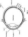
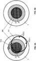
1 zeigt das menschliche Auge.1 shows the human eye.2 zeigt ein augenchirurgisches System.2 shows an ophthalmic surgical system.3 zeigt ein Andockverfahren.3 shows a docking procedure.4A-B veranschaulichen einen Ausrichtungsschritt.4A-B illustrate an alignment step.5 zeigt die Neigung und Verschiebung einer Linse relativ zur Andockeinheit.5 shows the inclination and displacement of a lens relative to the docking unit.6A-B veranschaulichen eine gekippte und verschobene Linse und ihr Bild.6A-B illustrate a tilted and shifted lens and its image.7 zeigt eine Verbesserung der Ausrichtung zwischen der Linse und der Andockeinheit.7th shows an improvement in alignment between the lens and the docking unit.8A-B veranschaulichen die Ausrichtung der Andockeinheit mit der Linse nach dem Schritt zur Verbesserung der Ausrichtung und das entsprechende Bild.8A-B illustrate the alignment of the docking unit with the lens after the step to improve the alignment and the corresponding image.9 zeigt ein Andockverfahren, das von einem Bildgebungsverfahren geführt wird.9 Figure 11 shows a docking process guided by an imaging process.10 zeigt ein bildgeführtes Andocksystem.10 shows an image-guided docking system.11 zeigt Teile des bildgeführten Andocksystems im Detail.11 shows parts of the image-guided docking system in detail.12 zeigt die Schritte eines Steuerverfahrens des bildgeführten Andockverfahrens.12 shows the steps of a control method of the image-guided docking method.
Ausführliche BeschreibungDetailed description
Viele augenchirurgische Systeme umfassen eine Andockeinheit oder eine Patientenschnittstelle, die Kontakt mit einem zu operierenden Auge herstellt und es während eines augenchirurgischen Eingriffs in Bezug auf ein Objektiv des chirurgischen Systems effektiv unbeweglich hält. Die Präzision des augenchirurgischen Eingriffs kann erhöht werden, indem die Präzision der Ausrichtung der Andockeinheit mit dem Ziel der Operation erhöht wird.Many ophthalmic surgical systems include a docking unit or patient interface that makes contact with an eye to be operated on and effectively holds it immobile with respect to an objective of the surgical system during an ophthalmic surgical procedure. The precision of the ophthalmic surgery can be increased by increasing the precision of the alignment of the docking unit with the target of the operation.
Bei Hornhautverfahren, bei denen das chirurgische Ziel - die Hornhaut - frei und sichtbar ist, kann der Chirurg die Ausrichtung der Patientenschnittstelle auf das Ziel relativ einfach durchführen.In corneal procedures where the surgical target - the cornea - is free and visible, the surgeon can relatively easily align the patient interface with the target.
Kataraktoperationen stellen jedoch aus mehreren Gründen größere Herausforderungen für die Ausrichtung und das Andocken der Patientenschnittstelle dar. Zu diesen Herausforderungen gehört, dass sich die Ziellinse im Auge befindet und daher für den Chirurgen weniger sichtbar oder teilweise versperrt ist.However, cataract surgery presents greater challenges to the alignment and docking of the patient interface for a number of reasons. These challenges include the target lens being in the eye and therefore less visible or partially obscured to the surgeon.
Außerdem haben Patienten häufig Schwierigkeiten, ihr zu operierendes Auge an der optischen Achse des augenchirurgischen Systems auszurichten, selbst wenn sie vom Chirurgen Hinweise und Anweisungen erhalten, da die Patienten z. B. oft Muskelrelaxantien erhalten oder stark sediert sind.In addition, patients often have difficulty in aligning their eye to be operated on the optical axis of the ophthalmic surgical system, even if they receive instructions and instructions from the surgeon, since the patient z. B. are often given muscle relaxants or are heavily sedated.
Ferner werden innere Augenstrukturen wie die Linse häufig von ihren weichen Stützmuskeln außermittig gehalten und relativ zu den sichtbaren Strukturen des Auges, wie der Pupille, geneigt. Selbst wenn es einem Chirurgen gelingt, die Pupille an der optischen Achse des chirurgischen Systems auszurichten, kann die Linse im Auge dennoch verschoben und gekippt werden.Furthermore, internal eye structures such as the lens are often held off-center by their soft support muscles and inclined relative to the visible structures of the eye such as the pupil. Even if a surgeon succeeds in aligning the pupil with the optical axis of the surgical system, the lens in the eye can still be moved and tilted.
Wenn die Andockeinheit auf das Auge abgesenkt wird, übt sie außerdem Druck auf das Auge aus, was möglicherweise zu einer zusätzlichen Verschiebung und Neigung der Linse führt. Dieses Problem kann durch Anwendung von Saugkraft zum Andocken der Patientenschnittstelle noch weiter verschärft werden.When the docking unit is lowered onto the eye, it also exerts pressure on the eye, possibly leading to additional displacement and tilting of the lens. This problem can be further exacerbated by using suction to dock the patient interface.
Implementierungen und Ausführungsformen in diesem Patentdokument stellen Andockverfahren und -systeme zur Erhöhung der Präzision des Andockverfahrens augenchirurgische Eingriffe durch Bildgebungstechniken bereit.Implementations and embodiments in this patent document provide docking methods and systems for increasing the precision of the docking method of ophthalmic surgery through imaging techniques.
Wie oben angegeben, ist die Linse
Implementierungen und Ausführungsformen in diesem Patentdokument stellen Andockverfahren und -systeme zur Erhöhung der Präzision des Andockverfahrens augenchirurgische Eingriffe durch Bildgebungstechniken bereit.Implementations and embodiments in this patent document provide docking methods and systems for increasing the precision of the docking method of ophthalmic surgery through imaging techniques.
Das chirurgische System
In einigen Implementierungen können Teile des Laser-x-y-z-Scanners
Eine Andockeinheit
Die chirurgischen und Andockverfahren können durch verschiedene Bildgebungssysteme unterstützt werden. In einigen chirurgischen Systemen
Das Abbildungslicht kann einen Teil des Hauptlichtwegs des chirurgischen Systems
Einige Implementierungen können im chirurgischen System
In einigen chirurgischen Systemen
Im Allgemeinen wird in diesem Dokument die Bezeichnung „x-y-z“ im weitesten Sinne verwendet: Sie kann sich auf das Abtasten in drei Richtungen beziehen, die erhebliche Winkel zueinander bilden. Diese Winkel müssen jedoch nicht unbedingt rechte Winkel sein. Das Abtasten kann auch entweder entlang gerader oder gekrümmter Linien auf flachen oder gekrümmten Oberflächen in einem Gitter, Raster, konzentrisch, spiralförmig oder einem anderen Muster durchgeführt werden. In einigen Implementierungen kann der OCT-Abbildungsstrahl durch den chirurgischen x-y-z-Laserscanner 52 abgetastet werden. In anderen Fällen werden nur einige der Scanfunktionen des chirurgischen Laserstrahls und des OCT-Bildgebungsstrahls von einem gemeinsam genutzten Scannerblock ausgeführt, beispielsweise die x-y-Scanfunktion. Einige OCT-Systeme, wie z. B. OCT-Systeme im Zeitbereich, erfordern eine Z-Abtastung des Strahls, während andere, wie z. B. spektrometerbasierte OCT-Systeme, keine Z-Abtastung erfordern, da sie Bilddaten aus allen Tiefen im Wesentlichen gleichzeitig erfassen.In general, the term "x-y-z" is used in the broadest sense in this document: it can refer to scanning in three directions that form significant angles to each other. However, these angles do not necessarily have to be right angles. Scanning can also be performed along either straight or curved lines on flat or curved surfaces in a grid, grid, concentric, spiral, or other pattern. In some implementations, the OCT imaging beam can be scanned by the x-y-z
Der OCT-Abbildungsstrahl kann durch einen Strahlteiler
Einen Ausrichtungsschritt 1 10 zum Ausrichten der Andockeinheit55 des augenchirurgischenSystems 50 und des Auges;Einen Bildgebungsschritt 120 zum Erzeugen eines Bildes einer inneren Struktur des Auges durch ein Bildgebungssystem;Einen Ausrichtungsverbesserungsschritt 130 zum Verbessern der Ausrichtung der Andockeinheit55 mit der inneren Struktur des Auges gemäß dem erzeugten Bild;und Einen Andockschritt 140 zum Andocken der Andockeinheit55 an das Auge.
- An
alignment step 1 10 for aligning thedocking unit 55 of theeye surgery system 50 and of the eye; - An
imaging step 120 for generating an image of an internal structure of the eye by an imaging system; - An
alignment improvement step 130 to improve the alignment of thedocking unit 55 with the internal structure of the eye according to the generated image; and adocking step 140 for docking thedocking unit 55 to the eye.
Diese Schritte werden nachstehend ausführlich beschrieben.These steps are detailed below.
Der Ausrichtungsschritt
Das Zielmuster des Augenlaserchirurgiesystems
Das Merkmal des Auges kann ein Zentrum eines Bereichs der Hornhaut
Der Radius des Zielmusterkreises
Während dieses Ausrichtungsschritts
In einigen Implementierungen beinhaltet der Ausrichtungsschritt
Ausführungsformen dieses Ausrichtungsschritts
In
Hier kann der Körper oder das Gehäuse
Die Andockeinheit
Daher ist der Zielmusterkreis
In anderen Implementierungen kann der Abbildungsschritt
Der Bildgebungsschritt
In einem Aspekt kann der Ausrichtungsverbesserungsschritt
In einer Implementierung kann der Chirurg das durch den Bildgebungsschritt
Die Verschiebung
Die Verschiebung
In einer Implementierung kann der Chirurg das durch den Abbildungsschritt
Die Drehung
Der Drehschritt
Einige Implementierungen können sowohl den ersten Zielmusterkreis
Ferner sind die Bilder der vorderen und hinteren Kapselsegmente
Das Erreichen der Ausrichtung der Andockeinheit
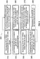
Ein Videoabbildungsschritt 310 zum Erzeugen eines Videomikroskopbildes eines Teils des Auges;Ein Zentrierschritt 320 zum Zentrieren einer Andockspitze gemäß dem Videomikroskopbild;- Ein OCT-
Bildgebungsschritt 330 zum Erzeugen eines OCT-Bildes eines Teils des Auges; Ein Distanzierungsschritt 340 zum Bestimmen eines Abstands der Andockspitze von der Hornhaut gemäß dem OCT-Bild;Ein Bewegungsschritt 350 zum Verwenden des bestimmten Abstands, um die Andockspitze in Richtung der Hornhaut des Auges zu bewegen;Ein Bestimmungsschritt 360 zum Bestimmen einer Position oder einer Ausrichtung einer Linse des Auges gemäß dem OCT-Bild;Ein Ausrichtungsschritt 370 zum Ausrichten der Andockspitze mit einer Augenlinse durch Anweisen des Patienten mit mündlichen Befehlen oder zum Einstellen eines Richtungslichts oder Bewegen eines Gerüsts; undEin Andockschritt 380 zum Anwenden von Saugkraft um die Andockspitze anzudocken.
- A
video mapping step 310 for generating a video microscope image of a portion of the eye; - A centering
step 320 for centering a docking tip according to the video microscope image; - An
OCT imaging step 330 for generating an OCT image of a part of the eye; - A step in distancing
340 for determining a distance of the docking tip from the cornea according to the OCT image; - One
movement step 350 to use the determined distance to move the docking tip toward the cornea of the eye; - A
determination step 360 for determining a position or an orientation of a lens of the eye according to the OCT image; - An
alignment step 370 aligning the docking tip with an eye lens by directing the patient with verbal commands, or adjusting a directional light or moving a scaffold; and - One
docking step 380 to apply suction to dock the docking tip.
Einige der Schritte
Die Funktionsprinzipien von OCT-Bildgebungssystemen sind bekannt und dokumentiert. Das OCT-System
Die spektrometerbasierten OCT-Systeme des Typs (c) verwenden eine Breitband-OCT-Bildgebungslichtquelle
Alle Arten von OCT-Abbildungseinheiten
Der OCT-Abbildungsstrahl kann durch den OCT-Strahl-x-y-Scanner
In all diesen Systemen kann der vom Auge zurückgeworfene OCT-Abbildungsstrahl mit dem vom OCT-Referenzspiegel
Bei sequentiellen OCT-Systemen kann diese OCT-Kamera
Der Bildgebungsprozess kann durch einen Bildgebungssynchronisationsblock
Als nächstes wird ein OCT-Abtaststrahlsteuerungssystem beschrieben, das die Schwierigkeiten des Betriebs einiger vorhandener OCT-Abtaststrahlsteuerungen löst, die als nächstes beschrieben werden.Next, an OCT scanning beam control system will be described which overcomes the difficulties of operating some of the existing OCT scanning beam controls which will be described next.
In einigen OCT-Bildgebungssystemen ist der Prozessor
Um diese Funktionen auszuführen, kann der Prozessor einen „Interrupt“ ausführen, indem er z. B. die Aufgabe den Strahl zu abzutasten zu einer anderen Aufgabe und zurück wechselt. Solche Interrupts, wie kurz sie auch sein mögen, können Probleme verursachen, da während der Zeit, in der das Abtasten durch den Interrupt gestoppt oder eingefroren wird, der Laserstrahl möglicherweise auf dieselbe Position gerichtet bleibt. Dieses Einfrieren des Abtastens kann das Timing des x-y-Scans stören und einen Fehler und Rauschen in die Koordinaten des abgebildeten Ortes einbringen. Dieser Zeitfehler in den ausgegebenen Abtastdaten kann zu Verzögerungen führen, die 50, 100 oder mehr Mikrosekunden dauern können: ein Phänomen, das manchmal als Jitter bezeichnet wird. Ferner kann die längere Exposition gegenüber dem Laserstrahl das empfindliche Augengewebe schädigen.In order to carry out these functions, the processor can execute an "interrupt" by e.g. B. the task of scanning the beam changes to another task and back. Such interrupts, however brief, can cause problems because the laser beam may remain in the same position during the time that the interrupt stops or freezes scanning. This freezing of the scan can upset the timing of the xy scan and introduce error and noise into the coordinates of the mapped location. This timing error in the output sample data can cause delays of 50, 100, or more microseconds: a phenomenon sometimes referred to as jitter. Furthermore, the longer exposure damage the sensitive eye tissue compared to the laser beam.
Außerdem, da der Prozessor typischerweise über einen Systembus mit Eingabe-/Ausgabeagenten kommuniziert, bietet dieser Ausgabemodus nur langsame Datenübertragungsraten, da mehrere Agenten gleichzeitig auf den Bus zugreifen können, alle einen Teil seiner Zykluszeit fordern. Um diese konkurrierenden Anforderungen zu verwalten, wird ferner ein Teil des Zyklus des Systembusses typischerweise von Steuersignalen eingenommen. Und wenn ein OCT-Bildgebungssystem so ausgelegt ist, dass dieses Einfrieren des Abtastens durch den Prozessor, der die Abtastdaten in einem Einzelaufgabenmodus an eine Ausgabeeinheit, z. B. über eine dedizierte Verbindung, ausgibt, vermieden wird, kann der Prozessor während dieses Ausgabeschritts keine anderen Funktionen ausführen, z. B. das nächste Abtastmuster berechnen. All diese Konstruktionen und Einschränkungen verlangsamen die Leistung solcher Systeme erheblich.In addition, since the processor typically communicates with input / output agents via a system bus, this output mode only offers slow data transfer rates, since several agents can access the bus simultaneously, all of which require part of its cycle time. In addition, to manage these competing requirements, part of the cycle of the system bus is typically occupied by control signals. And if an OCT imaging system is designed so that this freezing of the scanning by the processor, which sends the scanning data in a single task mode to an output unit, e.g. B. over a dedicated connection, is avoided, the processor cannot perform any other functions during this output step, e.g. B. calculate the next scan pattern. All of these designs and limitations significantly slow the performance of such systems.
Implementierungen der gegenwärtig beschriebenen OCT-Abtaststrahlsteuerung können diese Schwierigkeiten durch Verwendung einer effizienten Konstruktion überwinden. Die OCT-Abtaststrahlsteuerung kann den Prozessor
Der Prozessor
Die analoge Eingangs-/Ausgangsplatine
Bezüglich der oben beschriebenen Probleme mit anderen Systemen bieten Ausführungsformen der vorliegenden OCT-Abtaststrahlsteuerung eine schnelle Abtastoperation, da (i) der FIFO-Speicher
Aus all diesen Gründen wird die Ausgabe der Abtastdaten nicht durch konkurrierende Aufgaben unterbrochen oder durch die langsame Datenübertragung, die den gemeinsam genutzten Bus
Da der FIFO-Speicher
Zusätzlich wird die Ausgabe der Abtastdaten durch den Datenpuffer
In einigen Implementierungen kann der Ausgangs-DAC
Der Ausgangs-DAC
Zusätzlich kann der Bildgebungsschritt
Beispielsweise kann der erste Abbildungsschritt das Abtasten der x- und y-Koordinaten des Abbildungsstrahls entlang eines ersten Kreises eines ersten Radius umfassen. Wenn der zweite Bildgebungsschritt das Abtasten entlang eines zweiten Kreises eines zweiten Radius umfasst, kann dem ersten Bildgebungsschritt die Berechnung von Referenzdaten folgen, die einen Pfad vom Endpunkt des ersten kreisförmigen Scans mit dem ersten Radius zum Startpunkt des zweiten kreisförmigen Scans mit dem zweiten Radius definieren.For example, the first imaging step can include scanning the x and y coordinates of the imaging beam along a first circle of a first radius. If the second imaging step comprises scanning along a second circle of a second radius, the first imaging step may be followed by the calculation of reference data defining a path from the end point of the first circular scan with the first radius to the start point of the second circular scan with the second radius.
Durch solche Implementierungen kann es vermieden werden, den Abbildungsstrahl zurück zu einem Standardpunkt, z. B. zu einem Zentrum, Ursprung oder einem anderen zufällig gewählten Punkt, zu bewegen, wodurch zusätzliche Zeit gespart und der Abtastvorgang weiter beschleunigt wird.Such implementations can avoid having the imaging beam back to a standard point, e.g. B. to a center, origin or other randomly chosen point, which saves additional time and the scanning process is further accelerated.
Die Berechnung der Referenzierungsdaten kann auch bei Implementierungen nützlich sein, bei denen am Ende des ersten Bildgebungsschritts die x- und y-Galvos
In einigen Implementierungen kann die Geschwindigkeit des Ausgangs des Ausgangs-DAC
In einigen Implementierungen kann der Ausgang-DAC
In einigen Implementierungen kann die Ausgaberate der Abtastsignale gemäß den Anforderungen der Bildgebungsaufgabe und des -musters einstellbar sein.In some implementations, the output rate of the scan signals can be adjustable according to the requirements of the imaging task and pattern.
Sobald der Bildgebungsschritt
Der Schritt
Der Ausrichtungsverbesserungsschritt
Das Teilvakuum oder Ansaugen kann beispielsweise mit Hilfe eines Saugring oder einer Saugschürze, die Teil der Andockeinheit
Das Andockverfahren
In anderen Implementierungen kann das Andockverfahren
Die Schritte
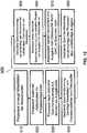
Einen Schritt 510 zur Berechnung von Abtaststeuerdatendurch den Prozessor 430/430' ;Einen Schritt 520 zur Speicherung derAbtaststeuerdaten im Prozessorspeicher 433 durch den Prozessor 430 ;Einen Schritt 530 zur Einrichtung der dedizierten Speichersteuerung440/440' für eine Abtastoperation durch Definieren von Betriebsparametern, wie beispielsweise einer Abtastausgangsrate;Einen Schritt 540 zur Übertragung vonAbtaststeuerdaten vom Prozessorspeicher 433 inden Datenpuffer 450/450' zumindest teilweise unter der Steuerung der dedizierten Speichersteuerung440/440' ;Einen Schritt 550 zur Benachrichtigung desProzessors 430/430' durch die dedizierte Speichersteuerung/DMA 440/440' , dass die Übertragung der Abtaststeuerdaten abgeschlossen ist;Einen Schritt 560 zur Anweisung der dedizierten Speichersteuerung440/440' durch den Prozessor 430/430' , eine schnelle Ausgabe der Abtaststeuerdaten zu starten;Einen Schritt 570 zur Übertragung derAbtaststeuerdaten vom Datenpuffer 450/450 zum Ausgangs-DAC 460/460' zumindest teilweise unter der Steuerung der dedizierten Speichersteuerung440/440' , wobei der Ausgangs-DAC 460/460' die digitalen Abtaststeuerdaten zu analogen Abtaststeuersignalen konvertiert und der Ausgangs-DAC 460/460' die analogen Abtaststeuersignale an die x- und y-Scanner 56a und56b und anden Synchronisationsblock 470 ausgibt;Einen Schritt 580 zur Benachrichtigung desProzessors 430/430' durch diededizierte Speichersteuerung 440/440' , dass der Ausgabeprozess abgeschlossen ist.
- One
step 510 for calculating scan control data by theprocessor 430/430 ' ; - One
step 520 for storing the scan control data in theprocessor memory 433 through theprocessor 430 ; - One
step 530 to set up thededicated memory control 440/440 ' for a sampling operation by defining operational parameters such as a sampling output rate; - One
step 540 for transferring scan control data from theprocessor memory 433 into thedata buffer 450/450 ' at least in part under the control of thededicated memory controller 440/440 ' ; - One
step 550 to notify theprocessor 430/430 ' through the dedicated memory controller /DMA 440/440 ' that the transfer of the scan control data is complete; - One
step 560 to instruct thededicated memory controller 440/440 ' through theprocessor 430/430 ' to start a quick output of the scan control data; - One
step 570 for transferring the scan control data from thedata buffer 450/450 to theoutput DAC 460/460 ' at least in part under the control of thededicated memory controller 440/440 ' , where theoutput DAC 460/460 ' converts the digital scan control data to analog scan control signals and theoutput DAC 460/460 ' the analog scan control signals to the x andy scanners 56a and56b and to the sync block470 issues; - One
step 580 to notify theprocessor 430/430 ' through thededicated memory control 440/440 ' that the output process is complete.
Im Schritt
Im Schritt
Im Schritt
Im Schritt
In einer Implementierung
- Ein Schritt
610 zur Berechnung von Abtaststeuerdaten durch einen Prozessor kannSchritt 510 umfassen; - Ein Schritt
620 zur Speicherung der Abtaststeuerdaten in einem Datenpuffer teilweise durch eine lokale Speichersteuerung kann dieSchritte 520 ,530 ,540 und 550 umfassen; - Ein Schritt
630 zur Übertragung der Abtaststeuerdaten in einem schnellen Übertragungsmodus aus dem Datenpuffer zu einem Wandlerausgangsmodul kann dieSchritte 560 und Elemente des Schritts570 umfassen; - Ein Schritt
640 zur Ausgabe von Abtastsignalen an Abtaststeuerungen, die Abtastsignale umgewandelt durch das Wandlerausgangsmodul aus den Abtaststeuerdaten, kann Elemente des Schritts570 enthalten.
- A step
610 for calculation of scan control data by a processor, step510 include; - A step
620 for storing the scan control data in a data buffer in part by a local memory controller, thesteps 520 ,530 ,540 and550 include; - A step
630 to transmit the scan control data in a fast transmission mode from the data buffer to a converter output module, thesteps 560 and elements of thestep 570 include; - A step
640 for outputting scanning signals to scanning controls, the scanning signals converted by the converter output module from the scanning control data, can elements ofstep 570 contain.
Obwohl diese Beschreibung viele Einzelheiten enthält, sollten diese nicht als Beschränkungen des Umfangs einer Erfindung oder dessen, was beansprucht werden kann, ausgelegt werden, sondern als Beschreibungen von Merkmalen, die für bestimmte Ausführungsformen spezifisch sind. Bestimmte Merkmale, die in dieser Beschreibung im Zusammenhang mit verschiedenen Ausführungsformen beschrieben sind, können auch in Kombination in einer einzelnen Ausführungsform implementiert werden. Umgekehrt können verschiedene Merkmale, die im Zusammenhang mit einer einzelnen Ausführungsform beschrieben werden, auch in mehreren Ausführungsformen separat oder in einer beliebigen geeigneten Unterkombination implementiert werden.While this description contains many details, these should not be construed as limitations on the scope of an invention or what can be claimed, but rather as descriptions of features that are specific to particular embodiments. Certain features that are described in this specification in connection with various embodiments can also be implemented in combination in a single embodiment. Conversely, various features that are described in connection with a single embodiment can also be implemented in multiple embodiments separately or in any suitable sub-combination.
Darüber hinaus können, obwohl oben beschrieben sein kann, dass Merkmale in bestimmten Kombinationen wirken und sogar anfänglich als solche beansprucht werden, ein oder mehrere Merkmale einer beanspruchten Kombination in einigen Fällen aus der Kombination entnommen werden, und die beanspruchte Kombination kann auf eine Unterkombination oder Variation einer Unterkombination gerichtet sein.Furthermore, although features may be described above as acting in certain combinations and even initially claimed as such, in some cases one or more features of a claimed combination may be extracted from the combination, and the claimed combination may refer to a sub-combination or variation a subcombination.
Claims (17)
Translated fromGermanApplications Claiming Priority (2)
| Application Number | Priority Date | Filing Date | Title |
|---|---|---|---|
| US12/815,179US8398236B2 (en) | 2010-06-14 | 2010-06-14 | Image-guided docking for ophthalmic surgical systems |
| US12/815,179 | 2010-06-14 |
Publications (1)
| Publication Number | Publication Date |
|---|---|
| DE202011111136U1true DE202011111136U1 (en) | 2020-10-12 |
Family
ID=45095987
Family Applications (3)
| Application Number | Title | Priority Date | Filing Date |
|---|---|---|---|
| DE202011111136.2UExpired - LifetimeDE202011111136U1 (en) | 2010-06-14 | 2011-06-13 | Eye surgical system |
| DE202011111135.4UWithdrawn - After IssueDE202011111135U1 (en) | 2010-06-14 | 2011-06-13 | Eye surgical system |
| DE202011111137.0UExpired - LifetimeDE202011111137U1 (en) | 2010-06-14 | 2011-06-13 | Eye surgical system |
Family Applications After (2)
| Application Number | Title | Priority Date | Filing Date |
|---|---|---|---|
| DE202011111135.4UWithdrawn - After IssueDE202011111135U1 (en) | 2010-06-14 | 2011-06-13 | Eye surgical system |
| DE202011111137.0UExpired - LifetimeDE202011111137U1 (en) | 2010-06-14 | 2011-06-13 | Eye surgical system |
Country Status (13)
| Country | Link |
|---|---|
| US (1) | US8398236B2 (en) |
| EP (1) | EP2579827B1 (en) |
| JP (1) | JP5848343B2 (en) |
| KR (1) | KR101818737B1 (en) |
| CN (1) | CN103167851B (en) |
| AU (1) | AU2011267981B2 (en) |
| BR (1) | BR112012031745B1 (en) |
| CA (1) | CA2801489C (en) |
| DE (3) | DE202011111136U1 (en) |
| ES (1) | ES2544992T3 (en) |
| MX (1) | MX2012014488A (en) |
| TW (1) | TWI584797B (en) |
| WO (1) | WO2011159627A2 (en) |
Families Citing this family (41)
| Publication number | Priority date | Publication date | Assignee | Title |
|---|---|---|---|---|
| US8409179B2 (en)* | 2007-12-17 | 2013-04-02 | Technolas Perfect Vision Gmbh | System for performing intrastromal refractive surgery |
| US8423186B2 (en) | 2009-06-30 | 2013-04-16 | Intuitive Surgical Operations, Inc. | Ratcheting for master alignment of a teleoperated minimally-invasive surgical instrument |
| US9492322B2 (en)* | 2009-11-16 | 2016-11-15 | Alcon Lensx, Inc. | Imaging surgical target tissue by nonlinear scanning |
| US9532708B2 (en) | 2010-09-17 | 2017-01-03 | Alcon Lensx, Inc. | Electronically controlled fixation light for ophthalmic imaging systems |
| US20120240939A1 (en)* | 2011-03-24 | 2012-09-27 | Jochen Kandulla | Apparatus and Method for Control of Refractive Index Changes in a Material |
| JP5289496B2 (en)* | 2011-03-31 | 2013-09-11 | キヤノン株式会社 | Ophthalmic equipment |
| US8398238B1 (en)* | 2011-08-26 | 2013-03-19 | Alcon Lensx, Inc. | Imaging-based guidance system for ophthalmic docking using a location-orientation analysis |
| JP6045170B2 (en)* | 2012-03-30 | 2016-12-14 | キヤノン株式会社 | Ophthalmic equipment |
| JP6024218B2 (en)* | 2012-06-02 | 2016-11-09 | 株式会社ニデック | Ophthalmic laser surgery device |
| US9603744B2 (en) | 2012-11-09 | 2017-03-28 | Technolas Perfect Vision Gmbh | Adaptable patient interface |
| US9398979B2 (en)* | 2013-03-11 | 2016-07-26 | Technolas Perfect Vision Gmbh | Dimensional compensator for use with a patient interface |
| EP3900684A1 (en)* | 2013-03-15 | 2021-10-27 | AMO Development, LLC | System and method for ophthalmic laser surgery employing eye tracking without eye docking |
| FR3007678B1 (en)* | 2013-06-28 | 2015-07-31 | Essilor Int | METHOD FOR MANUFACTURING AN OPHTHALMIC LENS COMPRISING A LASER MARKING STEP FOR REALIZING PERMANENT ENGRAVINGS ON A SURFACE OF THE OPHTHALMIC LENS |
| JP2015085044A (en)* | 2013-10-31 | 2015-05-07 | 株式会社ニデック | Ophthalmology imaging apparatus, ophthalmology imaging system, and ophthalmology imaging program |
| JP6524609B2 (en)* | 2014-03-31 | 2019-06-05 | 株式会社ニデック | Ophthalmic laser surgery device |
| CN106102632B (en)* | 2014-03-17 | 2019-06-14 | 直观外科手术操作公司 | Fix instrument control input bearing/orientation during in-program restart |
| DE102014111630B4 (en)* | 2014-08-14 | 2025-03-06 | Carl Zeiss Meditec Ag | Eye surgery device for inserting intraocular lenses into eyes |
| EP3186588B1 (en) | 2014-08-28 | 2018-10-24 | Johnson & Johnson Vision Care Inc. | In-line inspection of ophthalmic device with auto-alignment system and interferometer |
| JP6538841B2 (en)* | 2014-11-07 | 2019-07-03 | バイオプティジェン, インコーポレイテッドBioptigen, Inc. | Configurable light beam scanning drive system |
| WO2016159331A1 (en)* | 2015-03-31 | 2016-10-06 | 株式会社ニデック | Ophthalmic laser surgery device, ophthalmic device, ophthalmic device control program, and ophthalmic surgery control program |
| US9560959B1 (en)* | 2015-09-18 | 2017-02-07 | Novartis Ag | Control of scanning images during vitreoretinal surgery |
| US11003348B2 (en)* | 2015-10-13 | 2021-05-11 | Carl Zeiss Vision International Gmbh | Arrangement for determining the pupil center |
| US10219948B2 (en) | 2016-02-24 | 2019-03-05 | Perfect Ip, Llc | Ophthalmic laser treatment system and method |
| CN110786819B (en) | 2016-03-30 | 2022-07-26 | 索尼公司 | Surgical imaging system |
| EP3528758B1 (en) | 2016-10-19 | 2021-10-13 | Alcon Inc. | Systems for femtosecond laser ophthalmic surgery docking |
| CN111031946A (en) | 2017-08-09 | 2020-04-17 | 爱尔康公司 | Self-illuminating microsurgical intubation device |
| RU2665460C1 (en)* | 2017-10-19 | 2018-08-29 | Федеральное государственное автономное учреждение "Межотраслевой научно-технический комплекс "Микрохирургия глаза" имени академика С.Н. Федорова" Министерства здравоохранения Российской Федерации | Method of correction of corneal astigmatism by means of limbal relaxing incisions during phacoemulsification and implantation of aspherical iols using the verion-lensx system |
| CN107693287A (en)* | 2017-11-02 | 2018-02-16 | 王希娟 | A kind of eye examination apparatus |
| EP3675711A4 (en) | 2017-11-07 | 2021-06-30 | Notal Vision Ltd. | Retinal imaging device and related methods |
| CA3083825A1 (en) | 2017-11-07 | 2019-05-16 | Notal Vision Ltd. | Methods and systems for alignment of ophthalmic imaging devices |
| US11517474B2 (en) | 2017-12-19 | 2022-12-06 | Alcon Inc. | Methods and systems for eye illumination |
| CA3081561A1 (en)* | 2017-12-21 | 2019-06-27 | Alcon Inc. | Multi-view ophthalmic diagnostic systems |
| US10595722B1 (en) | 2018-10-03 | 2020-03-24 | Notal Vision Ltd. | Automatic optical path adjustment in home OCT |
| US11615526B2 (en) | 2019-03-27 | 2023-03-28 | Alcon Inc. | System and method of utilizing one or more images of an eye in medical procedures |
| US10653311B1 (en) | 2019-06-12 | 2020-05-19 | Notal Vision Ltd. | Home OCT with automatic focus adjustment |
| EP4069057A1 (en)* | 2019-12-05 | 2022-10-12 | Alcon Inc. | Surgical applications with integrated visualization camera and optical coherence tomography |
| CN111388187B (en)* | 2020-04-27 | 2023-10-20 | 季华实验室 | Ophthalmic docking device and docking method |
| CA3185731A1 (en)* | 2020-08-28 | 2022-03-03 | Mario Abraham | System for aligning an eye with a patient interface of an ophthalmic laser device |
| DE102020212850A1 (en)* | 2020-10-12 | 2022-04-14 | Carl Zeiss Meditec Ag | Method of centering a contact glass and refractive laser surgical system |
| FI131265B1 (en)* | 2022-06-09 | 2025-01-15 | Optomed Oyj | Ophthalmic apparatus and alignment method |
| DE102022121079A1 (en)* | 2022-08-19 | 2024-02-22 | Carl Zeiss Meditec Ag | REFRACTIVE SURGICAL LASER SYSTEM AND METHOD FOR DETERMINING A DISTANCE BETWEEN A CONTACT LENS AND A PATIENT'S EYE |
Family Cites Families (199)
| Publication number | Priority date | Publication date | Assignee | Title |
|---|---|---|---|---|
| SU728869A1 (en) | 1976-07-12 | 1980-04-25 | Физический Институт Им. П.Н.Лебедева Ан Ссср | Laser ophtalmology apparatus |
| JPS5926298B2 (en) | 1977-02-18 | 1984-06-26 | 東京光学機械株式会社 | Crystalline lens cross-section imaging device |
| JPS5926300B2 (en) | 1977-02-21 | 1984-06-26 | 東京光学機械株式会社 | Eyeball lens cross-section imaging device |
| JPS5663330A (en) | 1979-10-25 | 1981-05-29 | Canon Kk | Inspecting machine for eye |
| DE3045139A1 (en) | 1980-11-29 | 1982-07-01 | Fa. Carl Zeiss, 7920 Heidenheim | DEVICE FOR SUBJECTIVE AND OBJECTIVE REFLECTION DETERMINATION |
| FR2524298A1 (en) | 1982-04-01 | 1983-10-07 | Essilor Int | LASER OPHTHALMOLOGICAL SURGICAL APPARATUS |
| US4520816A (en) | 1983-01-12 | 1985-06-04 | Schachar Ronald A | Method and apparatus for delivering laser energy for ophthalmic use |
| US4638801A (en) | 1983-07-06 | 1987-01-27 | Lasers For Medicine | Laser ophthalmic surgical system |
| US4538608A (en) | 1984-03-23 | 1985-09-03 | Esperance Jr Francis A L | Method and apparatus for removing cataractous lens tissue by laser radiation |
| US4764005A (en)* | 1985-09-17 | 1988-08-16 | Eye Research Institute Of Retina Foundation | Double scanning optical apparatus |
| US4901718A (en) | 1988-02-02 | 1990-02-20 | Intelligent Surgical Lasers | 3-Dimensional laser beam guidance system |
| US4881808A (en) | 1988-02-10 | 1989-11-21 | Intelligent Surgical Lasers | Imaging system for surgical lasers |
| US4907586A (en) | 1988-03-31 | 1990-03-13 | Intelligent Surgical Lasers | Method for reshaping the eye |
| US5098426A (en) | 1989-02-06 | 1992-03-24 | Phoenix Laser Systems, Inc. | Method and apparatus for precision laser surgery |
| US6099522A (en) | 1989-02-06 | 2000-08-08 | Visx Inc. | Automated laser workstation for high precision surgical and industrial interventions |
| IL89874A0 (en) | 1989-04-06 | 1989-12-15 | Nissim Nejat Danon | Apparatus for computerized laser surgery |
| US5054907A (en) | 1989-12-22 | 1991-10-08 | Phoenix Laser Systems, Inc. | Ophthalmic diagnostic apparatus and method |
| US5048946A (en) | 1990-05-15 | 1991-09-17 | Phoenix Laser Systems, Inc. | Spectral division of reflected light in complex optical diagnostic and therapeutic systems |
| US5779696A (en) | 1990-07-23 | 1998-07-14 | Sunrise Technologies International, Inc. | Method and apparatus for performing corneal reshaping to correct ocular refractive errors |
| US5139022A (en) | 1990-10-26 | 1992-08-18 | Philip Lempert | Method and apparatus for imaging and analysis of ocular tissue |
| US5162641A (en) | 1991-02-19 | 1992-11-10 | Phoenix Laser Systems, Inc. | System and method for detecting, correcting and measuring depth movement of target tissue in a laser surgical system |
| JP3479069B2 (en) | 1991-04-29 | 2003-12-15 | マサチューセッツ・インステチュート・オブ・テクノロジー | Method and apparatus for optical imaging and measurement |
| US5255025A (en) | 1991-10-15 | 1993-10-19 | Volk Donald A | Measurement apparatus for indirect ophthalmoscopy |
| US5439462A (en) | 1992-02-25 | 1995-08-08 | Intelligent Surgical Lasers | Apparatus for removing cataractous material |
| US5246435A (en) | 1992-02-25 | 1993-09-21 | Intelligent Surgical Lasers | Method for removing cataractous material |
| US5549632A (en) | 1992-10-26 | 1996-08-27 | Novatec Laser Systems, Inc. | Method and apparatus for ophthalmic surgery |
| US5408504A (en) | 1992-12-30 | 1995-04-18 | Nokia Mobile Phones | Symbol and frame synchronization in a TDMA system |
| US5336215A (en) | 1993-01-22 | 1994-08-09 | Intelligent Surgical Lasers | Eye stabilizing mechanism for use in ophthalmic laser surgery |
| US5954711A (en) | 1993-12-28 | 1999-09-21 | Nidek Co., Ltd. | Laser treatment apparatus |
| US5656186A (en) | 1994-04-08 | 1997-08-12 | The Regents Of The University Of Michigan | Method for controlling configuration of laser induced breakdown and ablation |
| US5493109A (en) | 1994-08-18 | 1996-02-20 | Carl Zeiss, Inc. | Optical coherence tomography assisted ophthalmologic surgical microscope |
| EP1231496B1 (en) | 1994-08-18 | 2004-12-29 | Carl Zeiss AG | Optical coherence tomography assisted surgical apparatus |
| US5738676A (en) | 1995-01-03 | 1998-04-14 | Hammer; Daniel X. | Laser surgical probe for use in intraocular surgery |
| US6454761B1 (en) | 1995-01-30 | 2002-09-24 | Philip D. Freedman | Laser surgery device and method |
| ES2120878B1 (en) | 1996-01-05 | 1999-06-01 | Alejo Trevijano Jose Javier | ELECTRONIC STEREOSCOPIC SYSTEM. |
| WO1997040763A1 (en) | 1996-04-29 | 1997-11-06 | Philips Electronics N.V. | Image guided surgery system |
| US5795295A (en) | 1996-06-25 | 1998-08-18 | Carl Zeiss, Inc. | OCT-assisted surgical microscope with multi-coordinate manipulator |
| US6167296A (en) | 1996-06-28 | 2000-12-26 | The Board Of Trustees Of The Leland Stanford Junior University | Method for volumetric image navigation |
| US5777719A (en) | 1996-12-23 | 1998-07-07 | University Of Rochester | Method and apparatus for improving vision and the resolution of retinal images |
| US5994690A (en) | 1997-03-17 | 1999-11-30 | Kulkarni; Manish D. | Image enhancement in optical coherence tomography using deconvolution |
| DE19718139A1 (en) | 1997-04-30 | 1998-11-05 | Aesculap Meditec Gmbh | Phaco-emulsification method for intra=ocular tissue removal |
| JP3313309B2 (en) | 1997-08-21 | 2002-08-12 | 株式会社トプコン | Ophthalmic equipment |
| EP0941692B1 (en) | 1998-03-09 | 2002-09-11 | Schwind eye-tech-solutions GmbH & Co. KG | Method and device for examining the eye |
| DE19814057B4 (en) | 1998-03-30 | 2009-01-02 | Carl Zeiss Meditec Ag | Arrangement for optical coherence tomography and coherence topography |
| JP2003507081A (en) | 1998-04-27 | 2003-02-25 | ミン ライ | Optical tracking device |
| US6137585A (en) | 1998-05-15 | 2000-10-24 | Laser Diagnostic Technologies, Inc. | Method and apparatus for recording three-dimensional distribution of light backscattering potential in transparent and semi-transparent structures |
| EP1125095B1 (en) | 1998-09-11 | 2008-02-27 | Joseph A. Izatt | Interferometers for optical coherence domain reflectometry and optical coherence tomography using nonreciprocal optical elements |
| US6623476B2 (en) | 1998-10-15 | 2003-09-23 | Intralase Corp. | Device and method for reducing corneal induced aberrations during ophthalmic laser surgery |
| US6254595B1 (en) | 1998-10-15 | 2001-07-03 | Intralase Corporation | Corneal aplanation device |
| US6765956B1 (en) | 1999-04-28 | 2004-07-20 | Texas Instruments Incorporated | Multiple sampling frame synchronization in a wireline modem |
| US6497701B2 (en) | 1999-04-30 | 2002-12-24 | Visx, Incorporated | Method and system for ablating surfaces with partially overlapping craters having consistent curvature |
| DE19930408A1 (en) | 1999-07-02 | 2001-01-04 | Zeiss Carl Fa | An optical coherence computer tomography (OCT) system for surgical support combines pre-operation tissue position data and CT data for use in navigation assistance for the operating surgeon |
| US6817998B2 (en) | 1999-07-23 | 2004-11-16 | Lahaye Leon C. | Method and apparatus for monitoring laser surgery |
| US6314311B1 (en) | 1999-07-28 | 2001-11-06 | Picker International, Inc. | Movable mirror laser registration system |
| US6932807B1 (en) | 1999-09-01 | 2005-08-23 | Nidek Co., Ltd. | Laser treatment apparatus |
| US6687010B1 (en) | 1999-09-09 | 2004-02-03 | Olympus Corporation | Rapid depth scanning optical imaging device |
| HK1047533A1 (en) | 1999-09-10 | 2003-02-28 | Haag-Streit Ag | Method and device for the photoablation of the cornea with a laser beam |
| US6317616B1 (en) | 1999-09-15 | 2001-11-13 | Neil David Glossop | Method and system to facilitate image guided surgery |
| EP1240476A1 (en) | 1999-12-09 | 2002-09-18 | Oti Ophthalmic Technologies Inc. | Optical mapping apparatus with adjustable depth resolution |
| US6337925B1 (en) | 2000-05-08 | 2002-01-08 | Adobe Systems Incorporated | Method for determining a border in a complex scene with applications to image masking |
| DE10024079A1 (en) | 2000-05-17 | 2001-11-22 | Asclepion Meditec Ag | Determining energy and position of pulsed laser beam of ophthalmologic excimer laser for cornea surgery, deflects beam periodically onto measurement sensor |
| EP1289440B1 (en) | 2000-06-01 | 2010-01-20 | The General Hospital Corporation | Selective photocoagulation |
| US6652459B2 (en) | 2000-06-28 | 2003-11-25 | Peter Alfred Payne | Ophthalmic uses of lasers |
| US7025459B2 (en) | 2000-07-14 | 2006-04-11 | Visual Pathways, Inc. | Ocular fundus auto imager |
| US6451009B1 (en) | 2000-09-12 | 2002-09-17 | The Regents Of The University Of California | OCDR guided laser ablation device |
| US20020082466A1 (en) | 2000-12-22 | 2002-06-27 | Jeongho Han | Laser surgical system with light source and video scope |
| DE10100857B4 (en) | 2001-01-11 | 2006-05-18 | Carl Zeiss Jena Gmbh | Laser slit lamp with laser radiation source |
| US6863667B2 (en) | 2001-01-29 | 2005-03-08 | Intralase Corp. | Ocular fixation and stabilization device for ophthalmic surgical applications |
| US6899707B2 (en) | 2001-01-29 | 2005-05-31 | Intralase Corp. | Applanation lens and method for ophthalmic surgical applications |
| US20080071254A1 (en) | 2001-01-29 | 2008-03-20 | Advanced Medical Optics, Inc. | Ophthalmic interface apparatus and system and method of interfacing a surgical laser with an eye |
| US6775007B2 (en) | 2001-01-29 | 2004-08-10 | Joseph A. Izatt | Frequency-encoded parallel OCT and associated systems and methods |
| US6579282B2 (en) | 2001-04-25 | 2003-06-17 | 20/10 Perfect Vision Optische Geraete Gmbh | Device and method for creating a corneal reference for an eyetracker |
| JP2002345758A (en) | 2001-05-25 | 2002-12-03 | Canon Inc | Ophthalmic imaging equipment |
| AU2002337666A1 (en) | 2001-08-03 | 2003-02-17 | Joseph A. Izatt | Aspects of basic oct engine technologies for high speed optical coherence tomography and light source and other improvements in oct |
| US6751033B2 (en) | 2001-10-12 | 2004-06-15 | Intralase Corp. | Closed-loop focal positioning system and method |
| US7027233B2 (en) | 2001-10-12 | 2006-04-11 | Intralase Corp. | Closed-loop focal positioning system and method |
| US6980299B1 (en) | 2001-10-16 | 2005-12-27 | General Hospital Corporation | Systems and methods for imaging a sample |
| US7006231B2 (en) | 2001-10-18 | 2006-02-28 | Scimed Life Systems, Inc. | Diffraction grating based interferometric systems and methods |
| KR100679147B1 (en) | 2001-11-15 | 2007-02-27 | 가부시키가이샤 탑콘 | Optometry Device and Optometry Chart |
| EP1468245B1 (en) | 2002-01-11 | 2011-03-30 | The General Hospital Corporation | Apparatus for OCT imaging with axial line focus for improved resolution and depth of field |
| US7072045B2 (en) | 2002-01-16 | 2006-07-04 | The Regents Of The University Of California | High resolution optical coherence tomography with an improved depth range using an axicon lens |
| US7355716B2 (en) | 2002-01-24 | 2008-04-08 | The General Hospital Corporation | Apparatus and method for ranging and noise reduction of low coherence interferometry LCI and optical coherence tomography OCT signals by parallel detection of spectral bands |
| US20030171809A1 (en) | 2002-03-05 | 2003-09-11 | Phillips Andrew F. | Axial-displacement accommodating intraocular lens |
| US7006232B2 (en) | 2002-04-05 | 2006-02-28 | Case Western Reserve University | Phase-referenced doppler optical coherence tomography |
| US7113818B2 (en) | 2002-04-08 | 2006-09-26 | Oti Ophthalmic Technologies Inc. | Apparatus for high resolution imaging of moving organs |
| US6741359B2 (en) | 2002-05-22 | 2004-05-25 | Carl Zeiss Meditec, Inc. | Optical coherence tomography optical scanner |
| US6730074B2 (en) | 2002-05-24 | 2004-05-04 | 20/10 Perfect Vision Optische Geraete Gmbh | Cornea contact system for laser surgery |
| WO2003105678A2 (en) | 2002-06-12 | 2003-12-24 | Advanced Research And Technology Institute, Inc. | Method and apparatus for improving both lateral and axial resolution in ophthalmoscopy |
| US7133137B2 (en) | 2002-06-27 | 2006-11-07 | Visx, Incorporated | Integrated scanning and ocular tomography system and method |
| CA2390072C (en) | 2002-06-28 | 2018-02-27 | Adrian Gh Podoleanu | Optical mapping apparatus with adjustable depth resolution and multiple functionality |
| WO2004006751A2 (en) | 2002-07-12 | 2004-01-22 | Volker Westphal | Method and device for quantitative image correction for optical coherence tomography |
| EP1561263A4 (en) | 2002-10-17 | 2006-04-12 | Lumenis Inc | SYSTEM, METHOD AND APPARATUS FOR PRODUCING LASER BEAMS OF AT LEAST TWO WAVELENGTHS |
| JP4072897B2 (en) | 2002-10-28 | 2008-04-09 | 創輝H・S株式会社 | Gear pump and molding method thereof |
| US6887232B2 (en) | 2002-11-13 | 2005-05-03 | 20/10 Perfect Vision Optische Geraete Gmbh | Closed loop control for intrastromal wavefront-guided ablation |
| DE10252837B4 (en) | 2002-11-13 | 2005-03-24 | Carl Zeiss | Examination system and examination procedure |
| DE10300091A1 (en) | 2003-01-04 | 2004-07-29 | Lubatschowski, Holger, Dr. | microtome |
| WO2004068218A2 (en) | 2003-01-24 | 2004-08-12 | University Of Washington | Optical beam scanning system for compact image display or image acquisition |
| DE10304221A1 (en) | 2003-01-30 | 2004-08-12 | Carl Zeiss | Surgical assistance device for assisting a surgeon in the removal of tissue, e.g. for cancer treatment, whereby movement of an operating instrument is at least partially automated based on tissue measurements |
| US7846152B2 (en) | 2004-03-24 | 2010-12-07 | Amo Manufacturing Usa, Llc. | Calibrating laser beam position and shape using an image capture device |
| US7079254B2 (en) | 2003-03-26 | 2006-07-18 | Southwest Sciences Incorporated | Method and apparatus for imaging internal structures of transparent and translucent materials |
| US7742804B2 (en) | 2003-03-27 | 2010-06-22 | Ivan Faul | Means of tracking movement of bodies during medical treatment |
| WO2004098396A2 (en) | 2003-05-01 | 2004-11-18 | The Cleveland Clinic Foundation | Method and apparatus for measuring a retinal sublayer characteristic |
| US6927860B2 (en) | 2003-05-19 | 2005-08-09 | Oti Ophthalmic Technologies Inc. | Optical mapping apparatus with optimized OCT configuration |
| US20040267294A1 (en) | 2003-06-27 | 2004-12-30 | Will Brian R. | Eye fixation apparatus |
| US7311723B2 (en) | 2003-07-11 | 2007-12-25 | University Of Washington | Scanning laser device and methods of use |
| DE10360570B4 (en) | 2003-12-22 | 2006-01-12 | Carl Zeiss | Optical measuring system and optical measuring method |
| US7252661B2 (en) | 2003-12-23 | 2007-08-07 | Alcon Refractivehorizons, Inc. | Method and system for patient optical fixation |
| US7145661B2 (en) | 2003-12-31 | 2006-12-05 | Carl Zeiss Meditec, Inc. | Efficient optical coherence tomography (OCT) system and method for rapid imaging in three dimensions |
| JP4391259B2 (en) | 2004-02-03 | 2009-12-24 | 株式会社ニデック | Ophthalmic equipment |
| WO2005077256A1 (en) | 2004-02-06 | 2005-08-25 | Optovue, Inc. | Optical apparatus and methods for performing eye examinations |
| CA2553761A1 (en) | 2004-02-10 | 2005-08-25 | Optovue, Inc. | High efficiency low coherence interferometry |
| GB2411066B (en) | 2004-02-14 | 2009-04-29 | Oti Ophthalmic Technologies | Compact high resolution imaging apparatus |
| US7402159B2 (en) | 2004-03-01 | 2008-07-22 | 20/10 Perfect Vision Optische Geraete Gmbh | System and method for positioning a patient for laser surgery |
| KR101000926B1 (en) | 2004-03-11 | 2010-12-13 | 삼성전자주식회사 | Filters and Filtering Methods to Eliminate Image Discontinuities |
| JP4522724B2 (en) | 2004-03-16 | 2010-08-11 | 株式会社トプコン | Optical image measuring device |
| US7126693B2 (en) | 2004-03-29 | 2006-10-24 | Carl Zeiss Meditec, Inc. | Simple high efficiency optical coherence domain reflectometer design |
| JP4409332B2 (en) | 2004-03-30 | 2010-02-03 | 株式会社トプコン | Optical image measuring device |
| US7184148B2 (en) | 2004-05-14 | 2007-02-27 | Medeikon Corporation | Low coherence interferometry utilizing phase |
| US7452080B2 (en) | 2004-06-10 | 2008-11-18 | Optimedica Corporation | Scanning ophthalmic fixation method and apparatus |
| WO2006002392A2 (en) | 2004-06-24 | 2006-01-05 | Optimedica Corporation | Ophthalmic lens assembly utilizing replaceable contact element |
| US7352444B1 (en) | 2004-06-24 | 2008-04-01 | Cypress Semiconductor Corp. | Method for arranging and rotating a semiconductor wafer within a photolithography tool prior to exposing the wafer |
| WO2006005038A2 (en) | 2004-06-28 | 2006-01-12 | Optimedica Corporation | Method and device for optical ophthalmic therapy |
| DE102004035269A1 (en) | 2004-07-21 | 2006-02-16 | Rowiak Gmbh | Laryngoscope with OCT |
| JP4409384B2 (en) | 2004-08-03 | 2010-02-03 | 株式会社トプコン | Optical image measuring device and optical image measuring method |
| US7433046B2 (en) | 2004-09-03 | 2008-10-07 | Carl Ziess Meditec, Inc. | Patterned spinning disk based optical phase shifter for spectral domain optical coherence tomography |
| US7365859B2 (en) | 2004-09-10 | 2008-04-29 | The General Hospital Corporation | System and method for optical coherence imaging |
| JP4633423B2 (en) | 2004-09-15 | 2011-02-16 | 株式会社トプコン | Optical image measuring device |
| US7347553B2 (en) | 2004-09-24 | 2008-03-25 | Canon Kabushiki Kaisha | Ophthalmic image sensing apparatus |
| JP4566685B2 (en) | 2004-10-13 | 2010-10-20 | 株式会社トプコン | Optical image measuring device and optical image measuring method |
| JP4494160B2 (en) | 2004-10-14 | 2010-06-30 | 株式会社トプコン | Optical image measuring device |
| US7445336B2 (en) | 2004-10-21 | 2008-11-04 | Nidek Co., Ltd. | Fundus camera |
| US7252662B2 (en) | 2004-11-02 | 2007-08-07 | Lenticular Research Group Llc | Apparatus and processes for preventing or delaying one or more symptoms of presbyopia |
| US7388672B2 (en) | 2004-11-19 | 2008-06-17 | Carl Ziess Meditec, Inc. | High efficiency balanced detection interferometer |
| WO2006059669A1 (en) | 2004-12-01 | 2006-06-08 | Nidek Co., Ltd. | Ophthalmic instrument |
| JP4537192B2 (en) | 2004-12-21 | 2010-09-01 | キヤノン株式会社 | Ophthalmic equipment |
| US8394084B2 (en) | 2005-01-10 | 2013-03-12 | Optimedica Corporation | Apparatus for patterned plasma-mediated laser trephination of the lens capsule and three dimensional phaco-segmentation |
| US7336366B2 (en) | 2005-01-20 | 2008-02-26 | Duke University | Methods and systems for reducing complex conjugate ambiguity in interferometric data |
| US7633627B2 (en) | 2005-01-20 | 2009-12-15 | Duke University | Methods, systems and computer program products for characterizing structures based on interferometric phase data |
| US7330270B2 (en) | 2005-01-21 | 2008-02-12 | Carl Zeiss Meditec, Inc. | Method to suppress artifacts in frequency-domain optical coherence tomography |
| US7342659B2 (en) | 2005-01-21 | 2008-03-11 | Carl Zeiss Meditec, Inc. | Cross-dispersed spectrometer in a spectral domain optical coherence tomography system |
| US7365856B2 (en) | 2005-01-21 | 2008-04-29 | Carl Zeiss Meditec, Inc. | Method of motion correction in optical coherence tomography imaging |
| CA2595324C (en) | 2005-01-21 | 2015-08-11 | Massachusetts Institute Of Technology | Methods and apparatus for optical coherence tomography scanning |
| JP4504417B2 (en) | 2005-01-31 | 2010-07-14 | オリンパス株式会社 | Image processing apparatus, microscope system, and region specifying program |
| US7390089B2 (en) | 2005-02-25 | 2008-06-24 | 20/10 Perfect Vision Optische Geraete Gmbh | Device and method for aligning an eye with a surgical laser |
| JP4837300B2 (en) | 2005-03-24 | 2011-12-14 | 株式会社トプコン | Optical image measuring device |
| JP2008539036A (en) | 2005-04-26 | 2008-11-13 | バイオレーズ テクノロジー インコーポレイテッド | Device for treating ocular symptoms |
| US7207983B2 (en) | 2005-04-29 | 2007-04-24 | University Of Florida Research Foundation, Inc. | System and method for real-time feedback of ablation rate during laser refractive surgery |
| WO2007016296A2 (en) | 2005-07-28 | 2007-02-08 | Bioptigen, Inc. | Optical coherence imaging systems having a reduced effective linewidth and methods of using the same |
| GB2429522A (en) | 2005-08-26 | 2007-02-28 | Univ Kent Canterbury | Optical mapping apparatus |
| US20070129775A1 (en) | 2005-09-19 | 2007-06-07 | Mordaunt David H | System and method for generating treatment patterns |
| US10488606B2 (en) | 2005-09-19 | 2019-11-26 | Topcon Medical Laser Systems, Inc. | Optical switch and method for treatment of tissue |
| US7400410B2 (en) | 2005-10-05 | 2008-07-15 | Carl Zeiss Meditec, Inc. | Optical coherence tomography for eye-length measurement |
| US7606950B2 (en) | 2005-10-17 | 2009-10-20 | National Instruments Corporation | Graphical programs with direct memory access FIFO for controller/FPGA communications |
| US10524656B2 (en) | 2005-10-28 | 2020-01-07 | Topcon Medical Laser Systems Inc. | Photomedical treatment system and method with a virtual aiming device |
| US20070121069A1 (en) | 2005-11-16 | 2007-05-31 | Andersen Dan E | Multiple spot photomedical treatment using a laser indirect ophthalmoscope |
| US7593559B2 (en) | 2005-11-18 | 2009-09-22 | Duke University | Method and system of coregistrating optical coherence tomography (OCT) with other clinical tests |
| JP4837982B2 (en) | 2005-11-30 | 2011-12-14 | 株式会社ニデック | Ophthalmic equipment |
| US9681985B2 (en) | 2005-12-01 | 2017-06-20 | Topcon Medical Laser Systems, Inc. | System and method for minimally traumatic ophthalmic photomedicine |
| US7599591B2 (en) | 2006-01-12 | 2009-10-06 | Optimedica Corporation | Optical delivery systems and methods of providing adjustable beam diameter, spot size and/or spot shape |
| EP1994361B1 (en) | 2006-01-19 | 2016-07-27 | Optovue, Inc. | A fourier-domain optical coherence tomography imager |
| US8262646B2 (en) | 2006-01-20 | 2012-09-11 | Lensar, Inc. | System and method for providing the shaped structural weakening of the human lens with a laser |
| US20070173791A1 (en) | 2006-01-20 | 2007-07-26 | Intralase Corp. | System for ophthalmic laser surgery |
| US9889043B2 (en) | 2006-01-20 | 2018-02-13 | Lensar, Inc. | System and apparatus for delivering a laser beam to the lens of an eye |
| US10842675B2 (en) | 2006-01-20 | 2020-11-24 | Lensar, Inc. | System and method for treating the structure of the human lens with a laser |
| US9545338B2 (en) | 2006-01-20 | 2017-01-17 | Lensar, Llc. | System and method for improving the accommodative amplitude and increasing the refractive power of the human lens with a laser |
| US20070219541A1 (en) | 2006-03-14 | 2007-09-20 | Intralase Corp. | System and method for ophthalmic laser surgery on a cornea |
| US7768652B2 (en) | 2006-03-16 | 2010-08-03 | Carl Zeiss Meditec, Inc. | Methods for mapping tissue with optical coherence tomography data |
| JP4864516B2 (en) | 2006-04-07 | 2012-02-01 | 株式会社トプコン | Ophthalmic equipment |
| ES2817950T3 (en) | 2006-04-11 | 2021-04-08 | Cognoptix Inc | Eye imaging |
| US8771261B2 (en) | 2006-04-28 | 2014-07-08 | Topcon Medical Laser Systems, Inc. | Dynamic optical surgical system utilizing a fixed relationship between target tissue visualization and beam delivery |
| EP2012653B1 (en) | 2006-05-01 | 2012-12-12 | Physical Sciences, Inc. | Hybrid spectral domain optical coherence tomography line scanning laser ophthalmoscope |
| US7488930B2 (en) | 2006-06-02 | 2009-02-10 | Medeikon Corporation | Multi-channel low coherence interferometer |
| US20070291277A1 (en) | 2006-06-20 | 2007-12-20 | Everett Matthew J | Spectral domain optical coherence tomography system |
| US7452077B2 (en) | 2006-08-29 | 2008-11-18 | Carl Zeiss Meditec, Inc. | Image adjustment derived from optical imaging measurement data |
| US8223143B2 (en) | 2006-10-27 | 2012-07-17 | Carl Zeiss Meditec, Inc. | User interface for efficiently displaying relevant OCT imaging data |
| WO2008101359A1 (en) | 2007-02-23 | 2008-08-28 | Mimo Ag | Ophthalmologic apparatus for imaging an eye by optical coherence tomography |
| JP2010520801A (en) | 2007-03-13 | 2010-06-17 | オプティメディカ・コーポレイション | Apparatus for creating eye surgery and a detonation incision |
| US8568393B2 (en) | 2007-03-13 | 2013-10-29 | Topcon Medical Laser Systems, Inc. | Computer guided patterned laser trabeculoplasty |
| JP4896794B2 (en) | 2007-03-30 | 2012-03-14 | 株式会社トプコン | Optical image measuring apparatus, program for controlling the same, and optical image measuring method |
| US7575322B2 (en) | 2007-05-11 | 2009-08-18 | Amo Development Llc. | Auto-alignment and auto-focus system and method |
| JP5400040B2 (en)* | 2007-06-04 | 2014-01-29 | オラヤ セラピューティクス,インコーポレーテッド | Apparatus and assembly for eyeball positioning, stabilization, and treatment |
| DE112008002383T5 (en) | 2007-09-06 | 2010-06-24 | LenSx Lasers, Inc., Aliso Viejo | Precise targeting of surgical photodisruption |
| US7872761B2 (en) | 2007-09-14 | 2011-01-18 | OTI Ophthalmic Techlogies Inc. | Method for reliable optical coherence tomography scans of volumes of retinal tissue |
| US20100324543A1 (en) | 2007-09-18 | 2010-12-23 | Kurtz Ronald M | Method And Apparatus For Integrating Cataract Surgery With Glaucoma Or Astigmatism Surgery |
| US8409182B2 (en) | 2007-09-28 | 2013-04-02 | Eos Holdings, Llc | Laser-assisted thermal separation of tissue |
| JP4933413B2 (en) | 2007-12-11 | 2012-05-16 | 株式会社トーメーコーポレーション | Anterior segment optical coherence tomography apparatus and anterior segment optical coherence tomography method |
| US8230866B2 (en) | 2007-12-13 | 2012-07-31 | Carl Zeiss Meditec Ag | Systems and methods for treating glaucoma and systems and methods for imaging a portion of an eye |
| EP3272395B1 (en)* | 2007-12-23 | 2019-07-17 | Carl Zeiss Meditec, Inc. | Devices for detecting, controlling, and predicting radiation delivery |
| US7878651B2 (en) | 2007-12-26 | 2011-02-01 | Carl Zeiss Meditec, Inc. | Refractive prescription using optical coherence tomography |
| US8050296B2 (en) | 2008-03-31 | 2011-11-01 | Telefonaktiebolaget Lm Ericsson (Publ) | Radio equipment (RE)-based synchronization |
| US8783866B2 (en) | 2008-04-24 | 2014-07-22 | Bioptigen, Inc. | Optical coherence tomography (OCT) imaging systems having adaptable lens systems and related methods and computer program products |
| JP5255524B2 (en) | 2008-07-04 | 2013-08-07 | 株式会社ニデック | Optical tomographic imaging device, optical tomographic image processing device. |
| US20100022996A1 (en) | 2008-07-25 | 2010-01-28 | Frey Rudolph W | Method and system for creating a bubble shield for laser lens procedures |
| US8500723B2 (en) | 2008-07-25 | 2013-08-06 | Lensar, Inc. | Liquid filled index matching device for ophthalmic laser procedures |
| US8480659B2 (en) | 2008-07-25 | 2013-07-09 | Lensar, Inc. | Method and system for removal and replacement of lens material from the lens of an eye |
| US8240853B2 (en)* | 2009-05-01 | 2012-08-14 | Bioptigen, Inc. | Systems for imaging structures of a subject and related methods |
| JP2013500086A (en) | 2009-07-24 | 2013-01-07 | レンサー, インク. | System and method for performing a procedure using LADAR on an eye lens |
| US9492322B2 (en) | 2009-11-16 | 2016-11-15 | Alcon Lensx, Inc. | Imaging surgical target tissue by nonlinear scanning |
| US8845624B2 (en) | 2010-06-25 | 2014-09-30 | Alcon LexSx, Inc. | Adaptive patient interface |
- 2010
- 2010-06-14USUS12/815,179patent/US8398236B2/enactiveActive
- 2011
- 2011-06-13BRBR112012031745-8Apatent/BR112012031745B1/enactiveIP Right Grant
- 2011-06-13DEDE202011111136.2Upatent/DE202011111136U1/ennot_activeExpired - Lifetime
- 2011-06-13MXMX2012014488Apatent/MX2012014488A/enactiveIP Right Grant
- 2011-06-13KRKR1020137000984Apatent/KR101818737B1/enactiveActive
- 2011-06-13CACA2801489Apatent/CA2801489C/enactiveActive
- 2011-06-13EPEP11796256.3Apatent/EP2579827B1/ennot_activeRevoked
- 2011-06-13DEDE202011111135.4Upatent/DE202011111135U1/ennot_activeWithdrawn - After Issue
- 2011-06-13ESES11796256.3Tpatent/ES2544992T3/enactiveActive
- 2011-06-13DEDE202011111137.0Upatent/DE202011111137U1/ennot_activeExpired - Lifetime
- 2011-06-13AUAU2011267981Apatent/AU2011267981B2/enactiveActive
- 2011-06-13WOPCT/US2011/040223patent/WO2011159627A2/enactiveApplication Filing
- 2011-06-13JPJP2013515419Apatent/JP5848343B2/enactiveActive
- 2011-06-13CNCN201180035968.2Apatent/CN103167851B/enactiveActive
- 2011-06-14TWTW100120694Apatent/TWI584797B/ennot_activeIP Right Cessation
Also Published As
| Publication number | Publication date |
|---|---|
| WO2011159627A2 (en) | 2011-12-22 |
| CA2801489A1 (en) | 2011-12-22 |
| DE202011111135U1 (en) | 2020-09-30 |
| EP2579827A4 (en) | 2014-04-16 |
| KR20130085409A (en) | 2013-07-29 |
| DE202011111137U1 (en) | 2020-10-09 |
| AU2011267981B2 (en) | 2015-07-30 |
| CN103167851B (en) | 2015-03-11 |
| TW201219025A (en) | 2012-05-16 |
| WO2011159627A3 (en) | 2012-04-05 |
| AU2011267981A1 (en) | 2013-01-10 |
| ES2544992T3 (en) | 2015-09-07 |
| BR112012031745A2 (en) | 2016-11-01 |
| JP2013532026A (en) | 2013-08-15 |
| CN103167851A (en) | 2013-06-19 |
| BR112012031745B1 (en) | 2020-11-10 |
| KR101818737B1 (en) | 2018-01-15 |
| CA2801489C (en) | 2018-07-03 |
| MX2012014488A (en) | 2013-02-21 |
| TWI584797B (en) | 2017-06-01 |
| JP5848343B2 (en) | 2016-01-27 |
| US20110304819A1 (en) | 2011-12-15 |
| EP2579827B1 (en) | 2015-07-22 |
| RU2013101575A (en) | 2014-07-20 |
| EP2579827A2 (en) | 2013-04-17 |
| US8398236B2 (en) | 2013-03-19 |
Similar Documents
| Publication | Publication Date | Title |
|---|---|---|
| DE202011111136U1 (en) | Eye surgical system | |
| DE112008002448B4 (en) | Effective laser photodisruptive surgery in a gravitational field | |
| US9033500B2 (en) | Optical coherence tomography and method thereof | |
| US9615734B2 (en) | Ophthalmologic apparatus | |
| JP6117786B2 (en) | Imaging-based guidance system for eye docking using position and orientation analysis | |
| EP2497413A1 (en) | Photographing apparatus and photographing method | |
| EP2620097A1 (en) | Optical tomographic apparatus and control method thereof | |
| DE112008002446T5 (en) | Devices, systems and techniques for coupling with an eye in laser surgery | |
| EP2709577B1 (en) | Device for examining or treating a human eye | |
| CN103097855A (en) | Method and apparatus for enhanced eye measurement | |
| US10188286B2 (en) | Tomographic image capturing device | |
| US11089956B2 (en) | Ophthalmologic apparatus and method of controlling the same | |
| EP4321084A1 (en) | System for recording and visualizing oct signals | |
| DE102022127447A1 (en) | Lighting device, lighting method, lighting system and method for operating a lighting system | |
| RU2574576C2 (en) | Connection with control by images for ophthalmological surgical systems | |
| JP7512643B2 (en) | Ophthalmic image processing device and ophthalmic image processing program | |
| JP2014226173A (en) | Optical tomographic image generating device, method for controlling the optical tomographic image generating device, program therefor, and storage medium | |
| US20230293005A1 (en) | Control system for an oct imaging system, arrangement with an oct imaging system and method for adjusting an oct imaging system | |
| DE102023130922A9 (en) | System for determining a spatial arrangement of an optical instrument | |
| JP2024048735A (en) | Fundus photography device | |
| JP2021087762A (en) | Optical interference tomographic imaging device, control method of optical interference tomographic imaging device, and program |
Legal Events
| Date | Code | Title | Description |
|---|---|---|---|
| R152 | Utility model maintained after payment of third maintenance fee after eight years | ||
| R152 | Utility model maintained after payment of third maintenance fee after eight years | ||
| R207 | Utility model specification | ||
| R071 | Expiry of right |