DE202011109424U1 - Device for industrial wiring and final testing of photovoltaic concentrator modules - Google Patents
Device for industrial wiring and final testing of photovoltaic concentrator modulesDownload PDFInfo
- Publication number
- DE202011109424U1 DE202011109424U1DE202011109424UDE202011109424UDE202011109424U1DE 202011109424 U1DE202011109424 U1DE 202011109424U1DE 202011109424 UDE202011109424 UDE 202011109424UDE 202011109424 UDE202011109424 UDE 202011109424UDE 202011109424 U1DE202011109424 U1DE 202011109424U1
- Authority
- DE
- Germany
- Prior art keywords
- sensor carrier
- laser
- sensors
- concentrator modules
- wiring
- Prior art date
- Legal status (The legal status is an assumption and is not a legal conclusion. Google has not performed a legal analysis and makes no representation as to the accuracy of the status listed.)
- Withdrawn - After Issue
Links
- 238000013100final testMethods0.000titleclaimsdescription3
- 238000012360testing methodMethods0.000claimsabstractdescription17
- 238000009429electrical wiringMethods0.000claims1
- 238000007689inspectionMethods0.000abstract1
- 210000004027cellAnatomy0.000description13
- 238000004519manufacturing processMethods0.000description8
- 238000000034methodMethods0.000description7
- 239000000853adhesiveSubstances0.000description5
- 230000001070adhesive effectEffects0.000description5
- 238000001816coolingMethods0.000description4
- 239000000758substrateSubstances0.000description4
- 230000005855radiationEffects0.000description3
- 239000000565sealantSubstances0.000description3
- 238000007789sealingMethods0.000description3
- 239000006096absorbing agentSubstances0.000description2
- 150000001875compoundsChemical class0.000description2
- 239000004020conductorSubstances0.000description2
- 230000035699permeabilityEffects0.000description2
- 238000012545processingMethods0.000description2
- BUHVIAUBTBOHAG-FOYDDCNASA-N(2r,3r,4s,5r)-2-[6-[[2-(3,5-dimethoxyphenyl)-2-(2-methylphenyl)ethyl]amino]purin-9-yl]-5-(hydroxymethyl)oxolane-3,4-diolChemical compoundCOC1=CC(OC)=CC(C(CNC=2C=3N=CN(C=3N=CN=2)[C@H]2[C@@H]([C@H](O)[C@@H](CO)O2)O)C=2C(=CC=CC=2)C)=C1BUHVIAUBTBOHAG-FOYDDCNASA-N0.000description1
- XUIMIQQOPSSXEZ-UHFFFAOYSA-NSiliconChemical compound[Si]XUIMIQQOPSSXEZ-UHFFFAOYSA-N0.000description1
- 238000013459approachMethods0.000description1
- 210000002858crystal cellAnatomy0.000description1
- 230000007547defectEffects0.000description1
- 230000005611electricityEffects0.000description1
- 238000002372labellingMethods0.000description1
- 230000007774longtermEffects0.000description1
- 238000011160researchMethods0.000description1
- 239000004065semiconductorSubstances0.000description1
- 229910052710siliconInorganic materials0.000description1
- 239000010703siliconSubstances0.000description1
Images


Classifications
- H—ELECTRICITY
- H02—GENERATION; CONVERSION OR DISTRIBUTION OF ELECTRIC POWER
- H02S—GENERATION OF ELECTRIC POWER BY CONVERSION OF INFRARED RADIATION, VISIBLE LIGHT OR ULTRAVIOLET LIGHT, e.g. USING PHOTOVOLTAIC [PV] MODULES
- H02S50/00—Monitoring or testing of PV systems, e.g. load balancing or fault identification
- H02S50/10—Testing of PV devices, e.g. of PV modules or single PV cells
- H—ELECTRICITY
- H02—GENERATION; CONVERSION OR DISTRIBUTION OF ELECTRIC POWER
- H02S—GENERATION OF ELECTRIC POWER BY CONVERSION OF INFRARED RADIATION, VISIBLE LIGHT OR ULTRAVIOLET LIGHT, e.g. USING PHOTOVOLTAIC [PV] MODULES
- H02S30/00—Structural details of PV modules other than those related to light conversion
- H02S30/10—Frame structures
- H—ELECTRICITY
- H10—SEMICONDUCTOR DEVICES; ELECTRIC SOLID-STATE DEVICES NOT OTHERWISE PROVIDED FOR
- H10F—INORGANIC SEMICONDUCTOR DEVICES SENSITIVE TO INFRARED RADIATION, LIGHT, ELECTROMAGNETIC RADIATION OF SHORTER WAVELENGTH OR CORPUSCULAR RADIATION
- H10F19/00—Integrated devices, or assemblies of multiple devices, comprising at least one photovoltaic cell covered by group H10F10/00, e.g. photovoltaic modules
- H10F19/90—Structures for connecting between photovoltaic cells, e.g. interconnections or insulating spacers
- H10F19/902—Structures for connecting between photovoltaic cells, e.g. interconnections or insulating spacers for series or parallel connection of photovoltaic cells
- H—ELECTRICITY
- H10—SEMICONDUCTOR DEVICES; ELECTRIC SOLID-STATE DEVICES NOT OTHERWISE PROVIDED FOR
- H10F—INORGANIC SEMICONDUCTOR DEVICES SENSITIVE TO INFRARED RADIATION, LIGHT, ELECTROMAGNETIC RADIATION OF SHORTER WAVELENGTH OR CORPUSCULAR RADIATION
- H10F71/00—Manufacture or treatment of devices covered by this subclass
- H10F71/137—Batch treatment of the devices
- H10F71/1375—Apparatus for automatic interconnection of photovoltaic cells in a module
- H—ELECTRICITY
- H10—SEMICONDUCTOR DEVICES; ELECTRIC SOLID-STATE DEVICES NOT OTHERWISE PROVIDED FOR
- H10F—INORGANIC SEMICONDUCTOR DEVICES SENSITIVE TO INFRARED RADIATION, LIGHT, ELECTROMAGNETIC RADIATION OF SHORTER WAVELENGTH OR CORPUSCULAR RADIATION
- H10F77/00—Constructional details of devices covered by this subclass
- H10F77/40—Optical elements or arrangements
- H10F77/42—Optical elements or arrangements directly associated or integrated with photovoltaic cells, e.g. light-reflecting means or light-concentrating means
- H10F77/484—Refractive light-concentrating means, e.g. lenses
- F—MECHANICAL ENGINEERING; LIGHTING; HEATING; WEAPONS; BLASTING
- F21—LIGHTING
- F21S—NON-PORTABLE LIGHTING DEVICES; SYSTEMS THEREOF; VEHICLE LIGHTING DEVICES SPECIALLY ADAPTED FOR VEHICLE EXTERIORS
- F21S8/00—Lighting devices intended for fixed installation
- F21S8/006—Solar simulators, e.g. for testing photovoltaic panels
- G—PHYSICS
- G01—MEASURING; TESTING
- G01R—MEASURING ELECTRIC VARIABLES; MEASURING MAGNETIC VARIABLES
- G01R31/00—Arrangements for testing electric properties; Arrangements for locating electric faults; Arrangements for electrical testing characterised by what is being tested not provided for elsewhere
- G01R31/26—Testing of individual semiconductor devices
- H—ELECTRICITY
- H02—GENERATION; CONVERSION OR DISTRIBUTION OF ELECTRIC POWER
- H02S—GENERATION OF ELECTRIC POWER BY CONVERSION OF INFRARED RADIATION, VISIBLE LIGHT OR ULTRAVIOLET LIGHT, e.g. USING PHOTOVOLTAIC [PV] MODULES
- H02S50/00—Monitoring or testing of PV systems, e.g. load balancing or fault identification
- Y—GENERAL TAGGING OF NEW TECHNOLOGICAL DEVELOPMENTS; GENERAL TAGGING OF CROSS-SECTIONAL TECHNOLOGIES SPANNING OVER SEVERAL SECTIONS OF THE IPC; TECHNICAL SUBJECTS COVERED BY FORMER USPC CROSS-REFERENCE ART COLLECTIONS [XRACs] AND DIGESTS
- Y02—TECHNOLOGIES OR APPLICATIONS FOR MITIGATION OR ADAPTATION AGAINST CLIMATE CHANGE
- Y02E—REDUCTION OF GREENHOUSE GAS [GHG] EMISSIONS, RELATED TO ENERGY GENERATION, TRANSMISSION OR DISTRIBUTION
- Y02E10/00—Energy generation through renewable energy sources
- Y02E10/50—Photovoltaic [PV] energy
- Y02E10/52—PV systems with concentrators
- Y—GENERAL TAGGING OF NEW TECHNOLOGICAL DEVELOPMENTS; GENERAL TAGGING OF CROSS-SECTIONAL TECHNOLOGIES SPANNING OVER SEVERAL SECTIONS OF THE IPC; TECHNICAL SUBJECTS COVERED BY FORMER USPC CROSS-REFERENCE ART COLLECTIONS [XRACs] AND DIGESTS
- Y02—TECHNOLOGIES OR APPLICATIONS FOR MITIGATION OR ADAPTATION AGAINST CLIMATE CHANGE
- Y02P—CLIMATE CHANGE MITIGATION TECHNOLOGIES IN THE PRODUCTION OR PROCESSING OF GOODS
- Y02P80/00—Climate change mitigation technologies for sector-wide applications
- Y02P80/20—Climate change mitigation technologies for sector-wide applications using renewable energy
Landscapes
- Photovoltaic Devices (AREA)
- Investigating Materials By The Use Of Optical Means Adapted For Particular Applications (AREA)
- Testing Of Individual Semiconductor Devices (AREA)
- Tests Of Electronic Circuits (AREA)
Abstract
Translated fromGermanDescription
Translated fromGermanBereits seit vielen Jahren gibt es in der Photovoltaik Ansätze, mit konzentrierter Solarstrahlung zu arbeiten. Hierbei wird die Strahlung der Sonne mittels Spiegeln und/oder Linsen konzentriert, und auf spezielle Konzentrator-Solarzellen gerichtet. Entsprechende Systeme konzentrierender Photovoltaik (Concentrating Photovoltaics, CPV) werden derzeit im spanischen Solarforschungsinstitut Instituto de Sistemas Fotovoltaicos de Concentracion (ISFOC) in Kastilien bei Puertollano getestet. Sie bündeln das Sonnenlicht mit Linsen oder Spiegeln auf die vierhundert – bis tausendfache Intensität, bevor es auf kleine Solarzellen trifft, die deutlich effizienter sind als klassische Silizium-Solarzellen.For many years there have been approaches in photovoltaics to work with concentrated solar radiation. Here, the radiation of the sun is concentrated by means of mirrors and / or lenses, and directed to special concentrator solar cells. Corresponding Concentrating Photovoltaics (CPV) systems are currently being tested at the Spanish solar research institute Instituto de Sistemas Fotovoltaicos de Concentracion (ISFOC) in Castile near Puertollano. They focus sunlight with lenses or mirrors at four hundred to a thousand times the intensity before it encounters small solar cells, which are significantly more efficient than classic silicon solar cells.
Hierzu wird aus der Patentliteratur folgender Stand der Technik genannt.For this purpose, the following prior art is mentioned in the patent literature.
In der
Einer Anordnung von photovoltaischen Halbleiter-Kristallzellen, verteilt in individuellen Zell-Standorten in einem geschichteten Substrat, wobei diese von zwei elektrisch leitenden Schichten eingeschlossen und mittels einer Isolierschicht getrennt sind. Ferner besteht dieses Modul aus einer lichtfördernden Schicht aus Linsen die in einer Entfernung zu dem geschichteten Substrat angeordnet ist, wobei einfallende Strahlung in der lichtfördernden Schicht mittels der Linsen in das Substrat fokussiert wird, und wobei die gesamte Dicke der Linsenschicht, der Substratschicht und des Raums dazwischen ca. 2 inch beträgt.An array of photovoltaic semiconductor crystal cells distributed in individual cell sites in a layered substrate, enclosed by two electrically conductive layers and separated by an insulating layer. Furthermore, this module consists of a light-promoting layer of lenses which is arranged at a distance to the layered substrate, wherein incident radiation is focused in the light-promoting layer by means of the lenses in the substrate, and wherein the total thickness of the lens layer, the substrate layer and the space between them is about 2 inches.
Aus der
Diese bekannte Konzentratormodul soll dahingehend verbessert werden, dass es kastengünstig hergestellt werden kann, langlebig ist, und es erlaubt, einfach und flexibel zusätzliche Komponenten zu integrieren die auf der Linsenplatte oder der Bodenplatte nicht oder nur schwierig untergebracht werden können. Darüber hinaus soll ein Verfahren entwickelt werden, das die Herstellung solcher Konzentratormodule ermöglicht.This known concentrator module is to be improved in that it can be produced box-low, is durable, and allows to easily and flexibly integrate additional components that can not or only with difficulty be accommodated on the lens plate or the bottom plate. In addition, a method is to be developed, which allows the production of such concentrator modules.
Die hier gestellte Aufgabe wird dadurch gelöst, dass entlang des Rahmens zwischen der Linsenplatte und dem Rahmen und/oder der Bodenplatte und dem Rahmen zum einen mindestens eine erste Dichtmasse und/oder Klebemasse und zum anderen mindestens eine zweite Dichtmasse zumindest auf einem Teil der Länge des Rahmens umlaufend angeordnet ist, wobei die beiden Dicht- und/oder Klebemassen sich bezüglich ihrer Aushärtezeit und/oder Gasdurchlässigkeit unterscheiden.The object set here is achieved in that along the frame between the lens plate and the frame and / or the bottom plate and the frame on the one hand at least a first sealant and / or adhesive and on the other at least a second sealant at least on a part of the length of Surrounding frame is arranged, wherein the two sealing and / or adhesives differ with respect to their curing time and / or gas permeability.
Im Anspruch 57 wird ein Verfahren zur Herstellung eines photovoltaischen Konzentratormoduls nach einem der vorhergehenden Ansprüche beansprucht, das durch die folgenden Merkmale gekennzeichnet ist.Claim 57 claims a method for producing a photovoltaic concentrator module according to any one of the preceding claims, characterized by the following features.
Nämlich dass ein Rahmen, eine Linsenplatte und eine Bodenplatte verbindend, längs dem Rand der Linsenplatte und der Bodenplatte angeordnet wird, und dass zwischen den Rahmen und die Linsenplatte und/oder den Rahmen und die Bodenplatte zu einen mindestens eine erste Dichtmasse und/oder Klebemasse und zum anderen mindestens eine zweite Dichtmasse entlang des Rahmens über zumindest einen Teil seiner Länge umlaufend, eingebracht wird, wobei die beiden Dicht- und/oder Klebemassen sich bezüglich ihrer Aushärtezeiten und/oder Gasdurchlässigkeiten unterscheiden.Namely that a frame, a lens plate and a bottom plate connecting, along the edge of the lens plate and the bottom plate is arranged, and that between the frame and the lens plate and / or the frame and the bottom plate to at least a first sealant and / or adhesive and on the other hand, at least one second sealing compound is circulated along the frame over at least part of its length, whereby the two sealing and / or adhesive compounds differ with regard to their curing times and / or gas permeabilities.
Dass eine der Klebemassen zur Fixierung einer Platte während des Herstellungsprozesses mittels UV-Licht dient, ist hier nicht zu entnehmen.That one of the adhesives used to fix a plate during the manufacturing process by means of UV light, is not apparent here.
Die
Gemäß Anspruch 11 wird hier ein Verfahren zum elektrischen Verbinden einer Mehrzahl von Photovoltaikzellen beansprucht, wobei das Verfahren folgende Merkmale aufweist:
- 1) Aufbringen einer ersten Mehrzahl von Kontaktdrähten auf einer Vorderseite einer ersten Photovoltaikzelle,
- 2) Aufbringen einer zweiten Mehrzahl von Kontaktdrähten auf einer Rückseite der ersten Photovoltaikzelle,
- 3) Aufbringen der ersten Mehrzahl von Kontaktdrähten auf einer Rückseite einer zweiten Photovoltaikzelle, und
- 4) Aufbringen der zweiten Mehrzahl von Kontaktdrähten auf einer Vorderseite der zweiten Photovoltaikzelle, wobei
- 5) die erste Mehrzahl von Kontaktdrähten und die zweite Mehrzahl von Kontaktdrähten zueinander versetzt angeordnet werden.
- 1) applying a first plurality of contact wires on a front side of a first photovoltaic cell,
- 2) applying a second plurality of contact wires on a back side of the first photovoltaic cell,
- 3) applying the first plurality of contact wires on a back side of a second photovoltaic cell, and
- 4) applying the second plurality of contact wires on a front side of the second photovoltaic cell, wherein
- 5) the first plurality of contact wires and the second plurality of contact wires are offset from one another.
Als aufgabenähnliche Angabe ist dieser Druckschrift zu entnehmen, dass ein verbessertes Photovoltaikmodul kreiert werden soll, also die Kontaktstruktur der Photovoltaikzelle und die Anzahl und Dimension der Kontaktbändchen (Kontaktdrähte) kombiniert optimiert werdenAs a task-like statement, it can be seen that an improved photovoltaic module is to be created, that is to say the contact structure of the photovoltaic cell and the number and dimension of the contact strips (contact wires) can be optimized in combination
Der erfindungsgemäßen Vorrichtung bzw. dem entsprechenden Verfahren liegt die Aufgabe zugrunde, eine Vorrichtung und ein Verfahren vorzustellen mit dem industriell hergestellte Konzentratormodule industriell preiswert und zuverlässig verdrahtet werden können und eine zuverlässige Endprüfung durchgeführt werden kann, sodass im praktischen Betrieb eine hohe Langzeitstabilität eines Konzentratormoduls erreicht wirdThe device according to the invention or the corresponding method is based on the object of presenting a device and a method with which industrially produced concentrator modules can be industrially inexpensively and reliably wired and a reliable final test can be carried out so that a high long-term stability of a concentrator module is achieved in practical operation
Diese Aufgabe wird mit einer Vorrichtung nach Anspruch 1 gelöst.This object is achieved with a device according to
Die erfindungsgemäße Vorrichtung wird im Folgenden näher beschrieben. Es zeigen dabei im Einzelnen:The device according to the invention will be described in more detail below. In detail, they show:
In der
Hier wird jedoch nur der mit Bezugszeichen versehene Teil der gesamten Fertigungsanlage betrachtet. Der Fertigungsprozess bis zum Zeitpunkt der Verdrahtung eines Konzentratormoduls ist nicht Teil der Erfindung.Here, however, only the part provided with reference numerals of the entire manufacturing plant is considered. The manufacturing process up to the time of wiring a concentrator module is not part of the invention.
Zum Zeitpunkt der Verdrahtung eines solchen Moduls ist die Sensorträgerscheibe
Der Prüfplatz
Die Stapelplätze
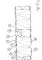
Die
Dieser lässt ein Konzentratormodul mit seinem tragenden Modulrahmen im Querschnitt in vergrößerter Darstellung erkennen. Auf der Oberseite sind hier jeweils eine Linsenscheibe
Die
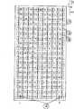
In der obersten Reihe der zahlenmäßig
Die
Die
In der unteren Bildhälfte der
In dem darunter gezeigten Querschnitt B-B ist entsprechend ein Verbindungselement
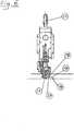
Zur Halterung der durch die Laser-Kontaktiereinrichtung zu verbindenden Kontaktierungselemente, bzw. Kontaktierungspartner, sind entsprechende Haltemittel vorgesehen, die lasergesteuert sich an speziellen Markierungen des Konzentratormoduls orientieren. Ihre Verwendung ist nicht gesondert dargestellt.For holding the contacting elements to be connected by the laser contacting device or contacting partners, corresponding holding means are provided which are laser-controlled and oriented on specific markings of the concentrator module. Their use is not shown separately.
Nach der Kontaktierung aller notwendigen elektrischen Verbindungen und dem Aufbringen einer Linsenscheibe
Nach der endgültigen Fertigstellung eines Konzentratormoduls werden die Konzentratormodule einer Einrichtung zur Dichtheitsprüfung (
Die Steuerung der komplexen Bewegungsvorgänge und die Signalverarbeitung der verwendeten Sensoren erfordern eine spezielle Regelung.The control of the complex movement processes and the signal processing of the sensors used require a special control.
Bezugszeichenliste LIST OF REFERENCE NUMBERS
- 11
- Laserkopflaser head
- 22
- Laserportallaser portal
- 33
- KontaktierplatzKontaktierplatz
- 44
- Stapelplätzestorehouses
- 55
- Prüfplatz (Dichteprüfung)Test station (density test)
- 66
- Prüfplatz (Elektrik)Test station (electrics)
- 77
- Mittelsteg eines KonzentratormodulsMiddle bar of a concentrator module
- 88th
- Sammel-Leitung (Minuspol)Collective line (negative pole)
- 99
- Sammel-Leitung (Pluspol)Collective line (positive pole)
- 1010
- Kühl- und KontaktplatteCooling and contact plate
- 1111
- CPV-Sensor (Absorber)CPV sensor (absorber)
- 1212
- Kontaktpunkt auf der Platte
10 Contact point on theplate 10 - 1313
- Sensorträgerscheibe eines KonzentratormodulsSensor carrier disk of a concentrator module
- 1414
- Kontaktpunkt eines CPV-Sensors (Absorbers)Contact point of a CPV sensor (absorber)
- 1515
- Linselens
- 1616
- Linsenscheibelens disk
- 1717
- Verbindungselement (Flachband oder Kabel)Connecting element (ribbon or cable)
- 1818
- Querträgercrossbeam
- 1919
- SammelkontaktplatteCollecting contact plate
- 2020
- Greifergrab
- 2121
- Laserlaser
- 2222
- Aufnahmeschaft für PortalträgerkopfShank for gantry head
ZITATE ENTHALTEN IN DER BESCHREIBUNG QUOTES INCLUDE IN THE DESCRIPTION
Diese Liste der vom Anmelder aufgeführten Dokumente wurde automatisiert erzeugt und ist ausschließlich zur besseren Information des Lesers aufgenommen. Die Liste ist nicht Bestandteil der deutschen Patent- bzw. Gebrauchsmusteranmeldung. Das DPMA übernimmt keinerlei Haftung für etwaige Fehler oder Auslassungen.This list of the documents listed by the applicant has been generated automatically and is included solely for the better information of the reader. The list is not part of the German patent or utility model application. The DPMA assumes no liability for any errors or omissions.
Zitierte PatentliteraturCited patent literature
- US 4834805 A[0003]US 4834805 A[0003]
- DE 102006007472 A1[0005]DE 102006007472 A1[0005]
- DE 102010016675 A1[0011]DE 102010016675 A1[0011]
Claims (4)
Translated fromGermanPriority Applications (22)
| Application Number | Priority Date | Filing Date | Title |
|---|---|---|---|
| DE202011109424UDE202011109424U1 (en) | 2011-12-23 | 2011-12-23 | Device for industrial wiring and final testing of photovoltaic concentrator modules |
| PCT/DE2012/001159WO2013091599A1 (en) | 2011-12-23 | 2012-12-06 | Method and device for the industrial wiring and final testing of photovoltaic concentrator modules |
| US14/353,733US9680411B2 (en) | 2011-12-23 | 2012-12-06 | Method and device for the industrial wiring and final testing of photovoltaic concentrator modules |
| ES12812824.6TES2548552T3 (en) | 2011-12-23 | 2012-12-06 | Procedure and device for industrial wiring and final testing of photovoltaic concentrator modules |
| KR1020147013390AKR101584467B1 (en) | 2011-12-23 | 2012-12-06 | Method and device for the industrial wiring and final testing of photovoltaic concentrator modules |
| EP12812824.6AEP2795353B8 (en) | 2011-12-23 | 2012-12-06 | Method and device for the industrial wiring and final testing of photovoltaic concentrator modules |
| JP2014547715AJP6113749B2 (en) | 2011-12-23 | 2012-12-06 | Method and apparatus for industrial wiring and final inspection of photovoltaic concentrator modules |
| CN201280053494.9ACN104040881B (en) | 2011-12-23 | 2012-12-06 | Photovoltaic concentrator module industry wiring and final test method and device |
| DE112012005423.7TDE112012005423A5 (en) | 2011-12-23 | 2012-12-06 | Method and device for industrial wiring and final testing of photovoltaic concentrator modules |
| US14/361,265US10103284B2 (en) | 2011-12-08 | 2012-12-07 | Apparatus for the industrial production of photovoltaic concentrator modules |
| CN201280060521.5ACN104106212B (en) | 2011-12-08 | 2012-12-07 | condensation photovoltaic battery array |
| EP12812520.0AEP2789016B1 (en) | 2011-12-08 | 2012-12-07 | Method for the industrial production of photovoltaic concentrator modules |
| PCT/EP2012/005069WO2013083283A1 (en) | 2011-12-08 | 2012-12-07 | Concentrating photovoltaic cell array |
| EP12812162.1AEP2789014B1 (en) | 2011-12-08 | 2012-12-07 | Concentrating photovoltaic cell array |
| FR1261799AFR2984012B1 (en) | 2011-12-08 | 2012-12-07 | APPARATUS FOR THE INDUSTRIAL PRODUCTION OF PHOTOVOLTAIC CONCENTRATING MODULES |
| ES12812162TES2728441T3 (en) | 2011-12-08 | 2012-12-07 | Matrix of photovoltaic concentration cells |
| FR1261800AFR2984011B1 (en) | 2011-12-08 | 2012-12-07 | APPARATUS FOR INDUSTRIAL WIRING AND FINAL TESTING OF PHOTOVOLTAIC CONCENTRATING MODULES |
| PCT/EP2012/005070WO2013083284A1 (en) | 2011-12-08 | 2012-12-07 | Apparatus for the industrial production of photovoltaic concentrator modules |
| CN201280060414.2ACN104025316B (en) | 2011-12-08 | 2012-12-07 | For the device of the industry manufacture of photovoltaic concentration module |
| US14/361,149US9640696B2 (en) | 2011-12-08 | 2012-12-07 | Concentrating photovoltaic cell array |
| ES12812520.0TES2668501T3 (en) | 2011-12-08 | 2012-12-07 | Method for industrial production of photovoltaic concentrator modules |
| CL2014001423ACL2014001423A1 (en) | 2011-12-23 | 2014-05-29 | Method and device for industrial wiring and the final testing of photovoltaic concentrator modules consisting of a module frame, a sensor lens panel and a power line guide, where the device also includes a contact arrangement by laser, a provision to test electrical properties and a provision to test the tightness of finished concentrator modules. |
Applications Claiming Priority (1)
| Application Number | Priority Date | Filing Date | Title |
|---|---|---|---|
| DE202011109424UDE202011109424U1 (en) | 2011-12-23 | 2011-12-23 | Device for industrial wiring and final testing of photovoltaic concentrator modules |
Publications (1)
| Publication Number | Publication Date |
|---|---|
| DE202011109424U1true DE202011109424U1 (en) | 2012-01-20 |
Family
ID=45756694
Family Applications (2)
| Application Number | Title | Priority Date | Filing Date |
|---|---|---|---|
| DE202011109424UWithdrawn - After IssueDE202011109424U1 (en) | 2011-12-08 | 2011-12-23 | Device for industrial wiring and final testing of photovoltaic concentrator modules |
| DE112012005423.7TWithdrawnDE112012005423A5 (en) | 2011-12-23 | 2012-12-06 | Method and device for industrial wiring and final testing of photovoltaic concentrator modules |
Family Applications After (1)
| Application Number | Title | Priority Date | Filing Date |
|---|---|---|---|
| DE112012005423.7TWithdrawnDE112012005423A5 (en) | 2011-12-23 | 2012-12-06 | Method and device for industrial wiring and final testing of photovoltaic concentrator modules |
Country Status (9)
| Country | Link |
|---|---|
| US (1) | US9680411B2 (en) |
| EP (1) | EP2795353B8 (en) |
| JP (1) | JP6113749B2 (en) |
| KR (1) | KR101584467B1 (en) |
| CN (1) | CN104040881B (en) |
| CL (1) | CL2014001423A1 (en) |
| DE (2) | DE202011109424U1 (en) |
| ES (1) | ES2548552T3 (en) |
| WO (1) | WO2013091599A1 (en) |
Families Citing this family (3)
| Publication number | Priority date | Publication date | Assignee | Title |
|---|---|---|---|---|
| FR3013172B1 (en)* | 2013-11-14 | 2015-11-20 | Soitec Solar Gmbh | DEVICE AND METHOD FOR TESTING A CONCENTRATION PHOTOVOLTAIC MODULE |
| ITTV20140024U1 (en)* | 2014-06-20 | 2015-12-20 | Vismunda Srl | "COMPACT EQUIPMENT FOR SEMI-AUTOMATIC ASSEMBLY OF PHOTOVOLTAIC PANELS" |
| CN118740046B (en)* | 2024-07-23 | 2025-09-23 | 应急管理部四川消防研究所 | Multifunctional photovoltaic array test bracket and method |
Citations (3)
| Publication number | Priority date | Publication date | Assignee | Title |
|---|---|---|---|---|
| US4834805A (en) | 1987-09-24 | 1989-05-30 | Wattsun, Inc. | Photovoltaic power modules and methods for making same |
| DE102006007472A1 (en) | 2006-02-17 | 2007-08-30 | Fraunhofer-Gesellschaft zur Förderung der angewandten Forschung e.V. | Photovoltaic concentrator module with multifunctional frame |
| DE102010016675A1 (en) | 2010-04-28 | 2011-11-03 | Solarworld Innovations Gmbh | Photovoltaic module, method for electrically connecting a plurality of photovoltaic cells, and means for electrically connecting a plurality of photovoltaic cells |
Family Cites Families (62)
| Publication number | Priority date | Publication date | Assignee | Title |
|---|---|---|---|---|
| US4149665A (en)* | 1977-11-04 | 1979-04-17 | Nasa | Bonding machine for forming a solar array strip |
| JPH07146201A (en)* | 1993-11-26 | 1995-06-06 | Nec Corp | Method and apparatus for testing airtightness |
| JPH08336893A (en) | 1995-06-13 | 1996-12-24 | Okura Ind Co Ltd | Method for manufacturing molded article having uneven pattern |
| JPH11243224A (en)* | 1997-12-26 | 1999-09-07 | Canon Inc | Photovoltaic element module, method of manufacturing the same, and non-contact processing method |
| JP2000269531A (en)* | 1999-01-14 | 2000-09-29 | Canon Inc | Solar cell module, building material with solar cell module, solar cell module enclosure, and solar power generation device |
| JP2001071171A (en)* | 1999-08-31 | 2001-03-21 | Canon Inc | Metal bonding equipment |
| JP4441102B2 (en)* | 1999-11-22 | 2010-03-31 | キヤノン株式会社 | Photovoltaic element and manufacturing method thereof |
| JP2002231983A (en)* | 2001-01-31 | 2002-08-16 | Canon Inc | Method for estimating characteristics of semiconductor film, method for manufacturing photovoltaic element using the same, and method for manufacturing solar cell module |
| NL1020627C2 (en)* | 2002-05-21 | 2003-11-24 | Otb Group Bv | Method and tab station for applying tabs to a solar cell as well as a method and device for manufacturing a solar panel. |
| US8153886B1 (en)* | 2003-10-20 | 2012-04-10 | Amonix, Inc. | Method of improving the efficiency of loosely packed solar cells in dense array applications |
| DE102005033272A1 (en)* | 2005-06-03 | 2006-12-07 | Solartec Ag | Concentrator photovoltaic device, PV concentrator module formed therefrom and manufacturing method thereof |
| JP2007146201A (en) | 2005-11-25 | 2007-06-14 | Nisshin Steel Co Ltd | Hot-dip aluminum-plated steel sheet having excellent spot weldability to aluminum material |
| JPWO2007125778A1 (en)* | 2006-04-28 | 2009-09-10 | シャープ株式会社 | Solar cell module evaluation apparatus, solar cell module evaluation method, and solar cell module manufacturing method |
| US20080142076A1 (en)* | 2006-12-15 | 2008-06-19 | Sol Focus, Inc. | Chamber for housing an energy-conversion unit |
| CN101226968A (en)* | 2007-01-17 | 2008-07-23 | 易斌宣 | Method for reducing series resistance of concentrating solar cell and concentrating solar cell obtained by the method |
| US8725459B2 (en)* | 2007-02-12 | 2014-05-13 | Locus Energy, Llc | Irradiance mapping leveraging a distributed network of solar photovoltaic systems |
| CN201018430Y (en)* | 2007-03-21 | 2008-02-06 | 万志强 | Solar energy concentration laser generator |
| US8013238B2 (en)* | 2007-07-09 | 2011-09-06 | Energy Related Devices, Inc. | Micro concentrators elastically coupled with spherical photovoltaic cells |
| JP4153021B1 (en)* | 2007-10-22 | 2008-09-17 | 日清紡績株式会社 | Solar cell inspection equipment |
| US20110041890A1 (en)* | 2007-11-19 | 2011-02-24 | Sheats James R | High-efficiency, high current solar cell and solar module |
| US8324497B2 (en)* | 2007-11-20 | 2012-12-04 | Sabic Innovative Plastics Ip B.V. | Luminescent solar concentrators |
| US7910035B2 (en)* | 2007-12-12 | 2011-03-22 | Solaria Corporation | Method and system for manufacturing integrated molded concentrator photovoltaic device |
| US8378661B1 (en)* | 2008-05-29 | 2013-02-19 | Alpha-Omega Power Technologies, Ltd.Co. | Solar simulator |
| US20090308426A1 (en)* | 2008-06-11 | 2009-12-17 | Kent Kernahan | Method and apparatus for installing, testing, monitoring and activating power generation equipment |
| DE102008031061A1 (en) | 2008-07-01 | 2011-01-05 | Grenzebach Maschinenbau Gmbh | Method and device for trimming photovoltaic modules |
| US20100012187A1 (en)* | 2008-07-18 | 2010-01-21 | Stellaris Corporation | Encapsulation of a photovoltaic concentrator |
| US20100011565A1 (en)* | 2008-07-21 | 2010-01-21 | Emcore Corporation | Methods of forming a lens sheet for a photovoltaic solar cell system |
| US8080729B2 (en)* | 2008-11-24 | 2011-12-20 | Palo Alto Research Center Incorporated | Melt planarization of solar cell bus bars |
| JP2010165995A (en) | 2009-01-19 | 2010-07-29 | Sharp Corp | Concentrator photovoltaic module |
| WO2010119841A1 (en)* | 2009-04-15 | 2010-10-21 | シャープ株式会社 | Solar cell panel inspecting apparatus, solar cell panel inspecting method, and solar cell panel manufacturing method |
| WO2011016441A1 (en)* | 2009-08-04 | 2011-02-10 | 国立大学法人奈良先端科学技術大学院大学 | Solar cell evaluation method, evaluation device, maintenance method, maintenance system, and method of manufacturing solar cell module |
| US9413174B2 (en)* | 2009-11-30 | 2016-08-09 | Atonometrics, Inc. | I-V measurement system for photovoltaic modules |
| US8519729B2 (en)* | 2010-02-10 | 2013-08-27 | Sunpower Corporation | Chucks for supporting solar cell in hot spot testing |
| US8610425B2 (en)* | 2010-05-04 | 2013-12-17 | Solmetric Corporation | Solar monitor for solar device |
| US8614787B2 (en)* | 2010-05-12 | 2013-12-24 | Intermolecular, Inc. | High throughput quantum efficiency combinatorial characterization tool and method for combinatorial solar test substrates |
| JP2012004447A (en)* | 2010-06-18 | 2012-01-05 | Yamashita Denso Kk | Solar simulator |
| TWI400459B (en)* | 2010-06-23 | 2013-07-01 | Nat Univ Tsing Hua | A method for parameters extraction of solar cells |
| EP2585841B1 (en)* | 2010-06-28 | 2015-09-09 | SMA Solar Technology AG | Device and method for monitoring a photovoltaic system |
| DE102010036514A1 (en)* | 2010-07-20 | 2012-01-26 | Sma Solar Technology Ag | Device and method for monitoring a photovoltaic system |
| US9054632B2 (en)* | 2010-08-06 | 2015-06-09 | First Solar, Inc. | In-process electrical connector |
| JP4944231B2 (en)* | 2010-08-11 | 2012-05-30 | コニカミノルタセンシング株式会社 | Solar cell evaluation device and light source evaluation device used therefor |
| US8731852B2 (en)* | 2010-09-28 | 2014-05-20 | Saint-Gobain Glass France | Method for analysing photovoltaic layer systems using thermography |
| WO2012051695A1 (en)* | 2010-10-18 | 2012-04-26 | Day4 Energy Inc. | Testing apparatus for photovoltaic cells |
| JP5819602B2 (en)* | 2010-11-29 | 2015-11-24 | Jx日鉱日石エネルギー株式会社 | Ground fault detection device, ground fault detection method, solar power generation system, and ground fault detection program |
| US8441276B2 (en)* | 2010-11-30 | 2013-05-14 | Tungnan University | Solar photovoltaic panel test platform |
| US20120152309A1 (en)* | 2010-12-17 | 2012-06-21 | Greenvolts, Inc | Alignment of photovoltaic cells with respect to each other during manufacturing and then maintaining this alignment in the field |
| JP5723611B2 (en)* | 2011-01-27 | 2015-05-27 | 株式会社日立製作所 | Solar power generation system, abnormality detection method, and abnormality detection system |
| US8841916B2 (en)* | 2011-02-28 | 2014-09-23 | Tigo Energy, Inc. | System and method for flash bypass |
| US8773156B2 (en)* | 2011-03-04 | 2014-07-08 | Applied Core Technologies, Inc. | Measurement of insulation resistance of configurable photovoltaic panels in a photovoltaic array |
| US20130014808A1 (en)* | 2011-07-14 | 2013-01-17 | Sabic Innovative Plastics Ip B.V. | Photovoltaic modules and methods for making and using the same |
| KR101248139B1 (en)* | 2011-09-28 | 2013-04-03 | 한국에너지기술연구원 | Light intensity measuring device and method for testing reliability of solar cell, and device and method for testing reliability of solar cell |
| DE102012000260B3 (en)* | 2012-01-10 | 2013-01-17 | Deutsches Zentrum für Luft- und Raumfahrt e.V. | Solar generator for e.g. spacecraft, has electrical conductors connected to the solar cells, whose physical integrity is tested by analyzing the electrical state of the electrical conductors |
| US8847614B2 (en)* | 2012-02-15 | 2014-09-30 | E Gear Llc | Electrical combiner box with improved functionality |
| JP5892597B2 (en)* | 2012-02-24 | 2016-03-23 | 株式会社Screenホールディングス | Inspection apparatus and inspection method |
| DE102012102456A1 (en)* | 2012-03-22 | 2013-09-26 | Komax Holding Ag | Arrangement and method for testing a solar module |
| CN103364731B (en)* | 2012-04-10 | 2016-06-01 | 致茂电子(苏州)有限公司 | Solar cell test system, method of testing and multifunctional test light source |
| US9513328B2 (en)* | 2012-04-23 | 2016-12-06 | Arizona Board Of Regents On Behalf Of Arizona State University | Systems and methods for eliminating measurement artifacts of external quantum efficiency of multi-junction solar cells |
| EP2670033B1 (en)* | 2012-05-29 | 2018-09-26 | ABB Schweiz AG | Starting of photovoltaic system |
| US20130328587A1 (en)* | 2012-06-06 | 2013-12-12 | Spire Corporation | Led solar simulator |
| US9057752B2 (en)* | 2012-09-11 | 2015-06-16 | Eaton Corporation | Method and apparatus for detecting a loose electrical connection in photovoltaic system |
| CN104184413A (en)* | 2013-05-27 | 2014-12-03 | 新科实业有限公司 | Test method and test device for solar panel |
| US20160064588A1 (en)* | 2014-08-28 | 2016-03-03 | James B. Paull | Concentrator lens for directing light to a photovoltaic target or mirrored surface and a dynamic window apparatus utilizing the same |
- 2011
- 2011-12-23DEDE202011109424Upatent/DE202011109424U1/ennot_activeWithdrawn - After Issue
- 2012
- 2012-12-06JPJP2014547715Apatent/JP6113749B2/ennot_activeExpired - Fee Related
- 2012-12-06KRKR1020147013390Apatent/KR101584467B1/ennot_activeExpired - Fee Related
- 2012-12-06DEDE112012005423.7Tpatent/DE112012005423A5/ennot_activeWithdrawn
- 2012-12-06EPEP12812824.6Apatent/EP2795353B8/ennot_activeNot-in-force
- 2012-12-06CNCN201280053494.9Apatent/CN104040881B/ennot_activeExpired - Fee Related
- 2012-12-06USUS14/353,733patent/US9680411B2/ennot_activeExpired - Fee Related
- 2012-12-06WOPCT/DE2012/001159patent/WO2013091599A1/enactiveApplication Filing
- 2012-12-06ESES12812824.6Tpatent/ES2548552T3/enactiveActive
- 2014
- 2014-05-29CLCL2014001423Apatent/CL2014001423A1/enunknown
Patent Citations (3)
| Publication number | Priority date | Publication date | Assignee | Title |
|---|---|---|---|---|
| US4834805A (en) | 1987-09-24 | 1989-05-30 | Wattsun, Inc. | Photovoltaic power modules and methods for making same |
| DE102006007472A1 (en) | 2006-02-17 | 2007-08-30 | Fraunhofer-Gesellschaft zur Förderung der angewandten Forschung e.V. | Photovoltaic concentrator module with multifunctional frame |
| DE102010016675A1 (en) | 2010-04-28 | 2011-11-03 | Solarworld Innovations Gmbh | Photovoltaic module, method for electrically connecting a plurality of photovoltaic cells, and means for electrically connecting a plurality of photovoltaic cells |
Also Published As
| Publication number | Publication date |
|---|---|
| EP2795353A1 (en) | 2014-10-29 |
| WO2013091599A1 (en) | 2013-06-27 |
| JP2015506655A (en) | 2015-03-02 |
| CL2014001423A1 (en) | 2014-11-14 |
| CN104040881A (en) | 2014-09-10 |
| DE112012005423A5 (en) | 2014-10-16 |
| KR20140103100A (en) | 2014-08-25 |
| JP6113749B2 (en) | 2017-04-12 |
| US9680411B2 (en) | 2017-06-13 |
| KR101584467B1 (en) | 2016-01-13 |
| ES2548552T3 (en) | 2015-10-19 |
| US20150236641A1 (en) | 2015-08-20 |
| EP2795353B1 (en) | 2015-08-12 |
| CN104040881B (en) | 2016-08-24 |
| EP2795353B8 (en) | 2015-09-30 |
Similar Documents
| Publication | Publication Date | Title |
|---|---|---|
| EP2353193B1 (en) | Method and device for fully automatically selecting and packing photovoltaic modules | |
| DE10107600C1 (en) | Method for operating a photovoltaic solar module and photovoltaic solar module | |
| WO2006128417A1 (en) | Concentrator photovoltaic device, pv concentrator module formed therefrom and production process therefor | |
| DE102007007140B4 (en) | Method and arrangement for detecting mechanical defects of a semiconductor device, in particular a solar cell or solar cell arrangement | |
| DE102008038184A1 (en) | Method and device for the temporary electrical contacting of a solar cell | |
| EP2304805A2 (en) | Method for producing a contact for solar cells | |
| DE202011108836U1 (en) | Apparatus for the industrial production of photovoltaic concentrator modules | |
| EP2101354A2 (en) | Device and method for forming dividing lines of a photovoltaic module with monolithically series connected cells | |
| EP2795353B1 (en) | Method and device for the industrial wiring and final testing of photovoltaic concentrator modules | |
| DE102009048691A1 (en) | DC measuring station for finding faulty PV modules in a PV system | |
| DE102008032555B3 (en) | Structuring device for the structuring of plate-shaped elements, in particular of thin-film solar modules, corresponding structuring method and use thereof | |
| EP3900051B1 (en) | Circuit configuration for power generation comprising series-connected solar cells having bypass diodes | |
| DE102008014258A1 (en) | Process for forming the dividing lines of a photovoltaic module with series-connected cells | |
| EP2984507B1 (en) | Device and method for optimally adjusting the lens plate in a cpv module | |
| EP1460447A1 (en) | Method and apparatus for error detection in electronic measuring and testing devices for galvanic cells | |
| DE112016006757B4 (en) | Method for monitoring a laser structuring process for forming isolation trenches in a solar module | |
| EP2947700A1 (en) | Small format photovoltaic module as glass-glass or glass-film laminate | |
| DE202013003394U1 (en) | Device for optimal adjustment of the lens plate in a CPV module | |
| EP3407035B1 (en) | Measuring device and method for measuring the intensity distribution of incident light radiation | |
| DE102010043905A1 (en) | Solar cell module and method for its production | |
| EP4472068A2 (en) | Test device for automated testing of an optoelectronic module | |
| DE102020203747A1 (en) | Method and arrangement for testing solar modules or solar cells for potential-induced degradation | |
| DE202021103628U1 (en) | PV module | |
| DE202009016849U1 (en) | Apparatus for processing thin-film solar modules and processing plant for thin-film solar modules | |
| DE102018002404A1 (en) | Sonnennachführeinheit |
Legal Events
| Date | Code | Title | Description |
|---|---|---|---|
| R086 | Non-binding declaration of licensing interest | ||
| R207 | Utility model specification | Effective date:20120315 | |
| R081 | Change of applicant/patentee | Owner name:SOITEC SOLAR GMBH, DE Free format text:FORMER OWNER: GRENZEBACH MASCHINENBAU GMBH, 86663 ASBACH-BAEUMENHEIM, DE Effective date:20130213 Owner name:GRENZEBACH MASCHINENBAU GMBH, DE Free format text:FORMER OWNER: GRENZEBACH MASCHINENBAU GMBH, 86663 ASBACH-BAEUMENHEIM, DE Effective date:20130213 | |
| R120 | Application withdrawn or ip right abandoned | ||
| R082 | Change of representative | Representative=s name:GRUENECKER PATENT- UND RECHTSANWAELTE PARTG MB, DE Representative=s name:GRUENECKER, KINKELDEY, STOCKMAIR & SCHWANHAEUS, DE | |
| R120 | Application withdrawn or ip right abandoned | Effective date:20131016 |