DE202011003952U1 - Illuminants for use in conventional sockets for fluorescent tubes - Google Patents
Illuminants for use in conventional sockets for fluorescent tubesDownload PDFInfo
- Publication number
- DE202011003952U1 DE202011003952U1DE202011003952UDE202011003952UDE202011003952U1DE 202011003952 U1DE202011003952 U1DE 202011003952U1DE 202011003952 UDE202011003952 UDE 202011003952UDE 202011003952 UDE202011003952 UDE 202011003952UDE 202011003952 U1DE202011003952 U1DE 202011003952U1
- Authority
- DE
- Germany
- Prior art keywords
- voltage
- operating
- illuminant
- illuminant according
- frequency
- Prior art date
- Legal status (The legal status is an assumption and is not a legal conclusion. Google has not performed a legal analysis and makes no representation as to the accuracy of the status listed.)
- Expired - Lifetime
Links
- 230000001939inductive effectEffects0.000claimsabstractdescription12
- 230000005540biological transmissionEffects0.000claimsabstractdescription11
- 238000005259measurementMethods0.000claimsdescription8
- 238000001514detection methodMethods0.000claimsdescription6
- 239000003990capacitorSubstances0.000claims1
- 238000002565electrocardiographyMethods0.000description7
- 239000000203mixtureSubstances0.000description5
- 239000011521glassSubstances0.000description4
- 239000007858starting materialSubstances0.000description4
- 239000011248coating agentSubstances0.000description3
- 238000000576coating methodMethods0.000description3
- 238000006243chemical reactionMethods0.000description2
- 239000004020conductorSubstances0.000description2
- 230000006978adaptationEffects0.000description1
- 150000002500ionsChemical class0.000description1
- 238000004519manufacturing processMethods0.000description1
- 238000012986modificationMethods0.000description1
- 230000004048modificationEffects0.000description1
- 230000007935neutral effectEffects0.000description1
- 230000010363phase shiftEffects0.000description1
- 230000002265preventionEffects0.000description1
- 238000000926separation methodMethods0.000description1
- 230000001629suppressionEffects0.000description1
- 230000009466transformationEffects0.000description1
Images
Classifications
- H—ELECTRICITY
- H05—ELECTRIC TECHNIQUES NOT OTHERWISE PROVIDED FOR
- H05B—ELECTRIC HEATING; ELECTRIC LIGHT SOURCES NOT OTHERWISE PROVIDED FOR; CIRCUIT ARRANGEMENTS FOR ELECTRIC LIGHT SOURCES, IN GENERAL
- H05B45/00—Circuit arrangements for operating light-emitting diodes [LED]
- H05B45/30—Driver circuits
- H05B45/357—Driver circuits specially adapted for retrofit LED light sources
- H05B45/3578—Emulating the electrical or functional characteristics of discharge lamps
- Y—GENERAL TAGGING OF NEW TECHNOLOGICAL DEVELOPMENTS; GENERAL TAGGING OF CROSS-SECTIONAL TECHNOLOGIES SPANNING OVER SEVERAL SECTIONS OF THE IPC; TECHNICAL SUBJECTS COVERED BY FORMER USPC CROSS-REFERENCE ART COLLECTIONS [XRACs] AND DIGESTS
- Y02—TECHNOLOGIES OR APPLICATIONS FOR MITIGATION OR ADAPTATION AGAINST CLIMATE CHANGE
- Y02B—CLIMATE CHANGE MITIGATION TECHNOLOGIES RELATED TO BUILDINGS, e.g. HOUSING, HOUSE APPLIANCES OR RELATED END-USER APPLICATIONS
- Y02B20/00—Energy efficient lighting technologies, e.g. halogen lamps or gas discharge lamps
- Y02B20/30—Semiconductor lamps, e.g. solid state lamps [SSL] light emitting diodes [LED] or organic LED [OLED]
Landscapes
- Circuit Arrangements For Discharge Lamps (AREA)
- Circuit Arrangement For Electric Light Sources In General (AREA)
Abstract
Translated fromGermanDescription
Translated fromGermanDie vorliegende Erfindung betrifft ein Leuchtmittel zur Verwendung in herkömmlichen Fassungen für Leuchtstoffröhren. Solche Leuchtmittel bestehen üblicherweise aus einer Prismenförmigen Rühre mit rundem Querschnitt, welcher an seinen Enden jeweils einen Anschluss für elektrische Energie aufweist. Über diese Anschlüsse kann elektrische Energie dem Leuchtmittel zugeführt werden, wodurch das Leuchtmittel dann Licht emittiert.The present invention relates to a lighting means for use in conventional fluorescent lamp sockets. Such bulbs usually consist of a prism-shaped agitator with a round cross section, which has at its ends in each case a connection for electrical energy. Electrical energy can be supplied to the lighting means via these connections, as a result of which the lighting means emits light.
Die bekannten Leuchtmittel verwenden einen Glaskörper, ein Gasgemisch innerhalb des röhrenförmigen Körpers, sowie eine spezielle Beschichtung an der Innenseite des Glaskörpers. Durch die elektrische Energie wird das Gasgemisch teilweise ionisiert. Die Ionen erzeugen dann, in dem Moment, in dem sie auf die spezielle Beschichtung treffen, Energie in Form von Licht, welches durch den Glaskörper nach außen emittiert wird.The known bulbs use a glass body, a gas mixture within the tubular body, as well as a special coating on the inside of the glass body. Due to the electrical energy, the gas mixture is partially ionized. The ions then generate energy in the form of light emitted by the glass body to the outside as soon as they hit the special coating.
Zum Betrieb solcher Leuchtmittel werden sogenannte Vorschaltgeräte eingesetzt. Im Prinzip gibt es zwei Arten von Vorschaltgeräten. Zu einen gibt es konventionelle Vorschaltgeräte (KVG), bestehend aus einer Drosselspule und einem sogenannten Starter. Im Leuchtmittel selber sind die elektrischen Anschlüsse als zwei Pole aus dem Leuchtmittel herausgeführt. Zwischen diesen Polen ist ein elektrischer Leiter angebracht. Der Starter ermöglicht zunächst, bei Einschalten des Leuchtmittels, einen Stromfluss über die elektrischen Leiter an den Anschlüssen. Nach einer Weile unterbricht dann der Starter den Stromfluss und es kommt zu einer hohen Zündspannung durch die Drosselspule. Durch diese Hohe Spannung wird ein Stromfluss innerhalb des Leuchtmittels erzeugt, welcher das Gasgemisch teilweise ionisiert und somit niederohmig macht. Danach fließt der Strom auch bei normaler Betriebsspannung durch das Leuchtmittel.For the operation of such bulbs so-called ballasts are used. In principle, there are two types of ballasts. For one there are conventional ballasts (CCG), consisting of a choke coil and a so-called starter. In the lamp itself, the electrical connections are led out of the lamp as two poles. Between these poles an electrical conductor is attached. The starter initially allows, when switching on the bulb, a current flow through the electrical conductors at the terminals. After a while, then the starter interrupts the current flow and there is a high ignition voltage through the choke coil. This high voltage generates a current flow within the luminous means, which partially ionizes the gas mixture and thus makes it low-impedance. Thereafter, the current flows through the lamp even at normal operating voltage.
Zum anderen gibt es elektronische Vorschaltgeräte (EVG). Diese besitzen keine Drosselspule und/oder Starter. Sie erzeugen eine hochfrequente Betriebsspannung, welche die Resonanzfrequenz des Leuchtmittels trifft. Durch die Resonanz entsteht eine hohe Betriebsspannung, welche als Zündspannung für das Leuchtmittel benutzt wird. Durch diese Hohe Spannung wird ein Stromfluss innerhalb des Leuchtmittels erzeugt, welcher das Gasgemisch teilweise ionisiert und somit niederohmig macht. Danach fließt der Strom auch bei normaler Betriebsspannung durch das Leuchtmittel, die aber dennoch durch das elektronische Vorschaltgerät hochfrequent ist.On the other hand there are electronic ballasts (ECG). These have no choke coil and / or starter. They generate a high-frequency operating voltage, which hits the resonant frequency of the lamp. The resonance creates a high operating voltage, which is used as ignition voltage for the light source. This high voltage generates a current flow within the luminous means, which partially ionizes the gas mixture and thus makes it low-impedance. Thereafter, the current also flows at normal operating voltage through the light source, which is nevertheless high-frequency by the electronic ballast.
Der Nachteil dieser herkömmlichen Leuchtmittel ist jedoch eine relativ hohe Verlustleistung bei den KVGs, sowie hohe Herstellungskosten bei den EVGs. Heutzutage sind mehr EVGs in Benutzung als die verlustreichen KVGs. Nach einer europäischen Richtlinie sollen diese Leuchtmittel jedoch mittelfristig abgeschafft werden und mit energiesparenden Leuchtmitteln ersetzt werden.The disadvantage of these conventional bulbs, however, is a relatively high power loss in the CCGs, as well as high production costs for ECGs. Today, more electronic ballasts are in use than the lossy CCGs. However, according to a European directive, these lamps are to be abolished in the medium term and replaced with energy-saving lamps.
Dadurch gibt es bereits Leuchtmittel, die statt ionisiertem Gas in Verbindung mit beschichtetem Glas als Leuchtkörper, LEDs als Leuchtköper verwenden. Nachteilig bei diesen Leuchtmitteln ist jedoch, dass sie mit den vorhandenen Fassungen für die Leuchtmittel nicht kompatibel sind, da diese Leuchtmittel nicht mit den oben genannten Vorschaltgeräten funktionieren. Ein Umbau der Fassung ist somit notwendig, um LEDs als Leuchtkörper betreiben zu können, da diese nicht mit variabler und/oder zu hoher Betriebsspannung betrieben werden können. Es ist somit Notwendig, die Versorgungsspannung der LEDs passend zu regulieren Aufgabe der vorliegenden Erfinden ist es also, ein Leuchtmittel, welches LEDs als Leuchtkörper verwendet, bereitzustellen, welches Kompatibel zu den Anschlüssen von herkömmlichen Fassungen für Leuchtstoffröhren ist und welches durch die vorhandenen Vorschaltgeräte (KVG oder EVG) betrieben werden kann.As a result, there are already bulbs that use instead of ionized gas in conjunction with coated glass as a luminous body, LEDs as luminous bodies. A disadvantage of these bulbs, however, is that they are not compatible with the existing sockets for the bulbs, as these bulbs do not work with the ballasts mentioned above. A conversion of the socket is thus necessary to operate LEDs as a filament, as they can not be operated with variable and / or high operating voltage. It is thus necessary to regulate the supply voltage of the LEDs appropriately. It is therefore an object of the present invention to provide a luminous means which uses LEDs as a luminous body, which is compatible with the connections of conventional sockets for fluorescent tubes and which is provided by the existing ballasts (KVG or electronic ballast).
Diese Aufgabe wird durch erfindungsgemäß durch die Merkmale des Anspruchs 1 gelöst. Das erfindungsgemäße Leuchtmittel ist ebenfalls als prismenförmige Röhre mit elektrischen Anschlüssen an beiden Enden ausgebildet. Dadurch lässt sich das erfindungsgemäße Leuchtmittel problemlos in vorhandene Fassungen für Leuchtstoffröhren einführen. Statt dem Gasgemisch und einer speziellen Beschichtung weist die vorliegende Erfindung jedoch mindestens eine LED als Leuchtkörper auf. Damit diese LEDs nicht durch variable oder zu hohe Betriebsspannungen beschädigt werden, wird eine Versorgungsspannung für die LEDs aus der jeweils vorhandenen Betriebsspannung generiert.This object is achieved by the invention by the features of claim 1. The luminous means according to the invention is likewise designed as a prismatic tube with electrical connections at both ends. As a result, the luminous means according to the invention can be easily introduced into existing sockets for fluorescent tubes. However, instead of the gas mixture and a special coating, the present invention has at least one LED as a luminous body. So that these LEDs are not damaged by variable or too high operating voltages, a supply voltage for the LEDs is generated from the respective operating voltage.
Dazu ist es zunächst notwendig, dass das Leuchtmittel erkennt, ob ein KVG oder ein EVG zum Betrieb des Leuchtmittels verwendet wird. Zur Erkennung ist eine Wechselspannungsidentifikation im Leuchtmittel vorgesehen. Diese kann durch Mittel für eine Frequenzmessung geschehen und/oder durch Spannungsmessung. Bei der Frequenzmessung wird festgestellt, ob gerade eine hochfrequente Betriebsspannung an den Anschlüssen anliegt. Da die hochfrequenten Spannungen der EVGs wesentlich höher liegen als die normale Netzfrequenz von 50 oder 60 Hz (beispielsweise bei 40 KHz), sind sie durch Frequenzmessung einfach festzustellen. Bei der Spannungsmessung wird die Höhe der Spannung gemessen. Da die EVGs versuchen, eine Resonanz im Leuchtmittel hervorzurufen, entstehen höhere Betriebsspannungen als bei KVGs in Verbindung mit der erfindungsgemäßen Vorrichtung. Durch ein Mittel zur induktiven Hochfrequenzübertragung (beispielsweise durch einen handelsüblichen Hochfrequenz- oder RF-Übertrager) ist der elektrische Widerstand am Anschluss des Leuchtmittels ähnlich zu dem Widerstand am Anschluss handelsüblicher Leuchtstoffröhren. Somit kann durch Spannungsmessung ebenfalls einfach festgestellt werden, welche Art von Vorschaltgerät benutzt wird.For this purpose, it is first necessary that the light source detects whether a CCG or a ballast is used to operate the bulb. To detect an AC voltage identification is provided in the bulb. This can be done by means for a frequency measurement and / or by voltage measurement. During the frequency measurement, it is determined whether a high-frequency operating voltage is currently being applied to the connections. Since the high-frequency voltages of the ECGs are much higher than the normal mains frequency of 50 or 60 Hz (for example, at 40 kHz), they are easily detected by frequency measurement. In the voltage measurement, the height of the voltage is measured. Since the ECGs try to cause a resonance in the lamp, higher operating voltages than in KVGs in connection with the device according to the invention arise. By a means for inductive high-frequency transmission (for example, by a commercial high frequency or RF transformer) is the electrical resistance at the connection of the lamp similar to the resistance at the connection of commercially available fluorescent tubes. Thus, it can also be easily determined by voltage measurement, which type of ballast is used.
Nach der erfolgreichen Erkennung des Vorschaltgeräts muss aus der jeweils vorhandenen Betriebsspannung eine Versorgungsspannung für den Leuchtkörper erzeugt werden. Dazu sind zwei getrennte Spannungserzeugungen innerhalb des Leuchtmittels vorgesehen. Damit diese nicht gleichzeitig betrieben werden, sind sie schaltungstechnisch voneinander getrennt. Diese Trennung übernimmt mindestens ein elektrischer oder elektronischer Schalter. Dieser kann zum Beispiel ein Relais, ein TRIAC oder ähnliches sein. Angesteuert werden diese Relais durch die Wechselspannungsidentifikation. Dadurch entstehen in dem Leuchtmittel zwei Betriebsmodi.After the successful detection of the ballast, a supply voltage for the lamp must be generated from the existing operating voltage. For this purpose, two separate voltage generations are provided within the lamp. So that they are not operated simultaneously, they are separated from each other by circuitry. This separation is carried out by at least one electrical or electronic switch. This can be, for example, a relay, a TRIAC or similar. These relays are controlled by AC voltage identification. This creates two operating modes in the light source.
Im ersten Betriebsmodus wird eine niederfrequente Spannung als Betriebsspannung erkannt (KVG). Die Betriebsspannung des Leuchtmittels wird einer Gleichrichtung zugeführt. Dies kann beispielsweise durch einen AC/DC Standard LED Treiber geschehen. Die Wechselspannungsidentifikation steuert den Schalter nun so an, dass die gleichgerichtete Betriebsspannung des Leuchtmittels als Versorgungsspannung den LEDs zugeführt wird.In the first operating mode, a low-frequency voltage is detected as the operating voltage (KVG). The operating voltage of the lamp is supplied to a rectification. This can be done for example by an AC / DC standard LED driver. The alternating voltage identification controls the switch now so that the rectified operating voltage of the lamp is supplied as a supply voltage to the LEDs.
Im zweiten Betriebsmodus wird eine hochfrequente Spannung als Betriebsspannung erkannt (EVG). Die hochfrequente Betriebsspannung des Leuchtmittels wird über Mittel zur induktiven Hochfrequenzübertragung induktiv übertragen und einer zweiten, entsprechenden Gleichrichtung zugeführt. Dies kann beispielsweise durch einen Hochfrequenz-Transformator mit LED Treiber geschehen. Die Betriebsspannung kann dabei sinus-, sägezahn- oder rechteckförmig sein. Die Wechselspannungsidentifikation steuert den Schalter nun so an, dass die gleichgerichtete hochfrequente Betriebsspannung des Leuchtmittels als Versorgungsspannung den LEDs zugeführt wird. Das Mittel zur induktiven Hochfrequenzübertragung dient also zur Übertragung der Versorgungsspannung und somit des Versorgungsstroms im Falle von EVGs und gleichzeitig als simulierte elektrische Leitung an den Anschlüssen im Falle von KVGs und EVGs.In the second operating mode, a high-frequency voltage is detected as the operating voltage (ECG). The high-frequency operating voltage of the luminous means is inductively transmitted via means for inductive high-frequency transmission and fed to a second, corresponding rectification. This can be done for example by a high-frequency transformer with LED driver. The operating voltage can be sinusoidal, sawtooth or rectangular. The alternating voltage identification controls the switch now so that the rectified high-frequency operating voltage of the lamp is supplied as a supply voltage to the LEDs. The means for inductive high-frequency transmission thus serves to transmit the supply voltage and thus the supply current in the case of electronic ballasts and at the same time as a simulated electrical line at the terminals in the case of CCGs and electronic ballasts.
Durch die simulierten Anschlüsse werden die erfindungsgemäßen Leuchtmittel auch bei einer Fehlerdetektion, wie sie von EVGs ausgeführt werden, als normale Leuchtmittel erkannt und nicht als fehlerhaft deklariert.As a result of the simulated connections, the illuminants according to the invention are recognized as normal illuminants even in the case of fault detection, as they are performed by electronic ballasts, and are not declared as faulty.
Zum Schutz vor Verpolung der Anschlüsse ist mindestens ein Phasenrichter und/oder Nullrichter vorgesehen. Diese detektieren die Phasenlage der elektrischen Anschlüsse. Über die Wechselspannungsidentifikation und den Schalter werden die Phasen- und/oder Nullrichter nur im Falle der KVGs zugeschaltet. Bei dem zweiten Betriebsmodus ist eine Verpolung unerheblich, da die Versorgungsspannung nur über die induktive Übertragung erzeugt wird. Bei dem ersten Betriebsmodus jedoch, muss eine richtige Polung gewährleistet sein.At least one phase judge and / or zero judge is provided to protect against reverse polarity of the terminals. These detect the phase position of the electrical connections. About the AC identification and the switch, the phase and / or zero rectifier are connected only in the case of KVGs. In the second operating mode, a reverse polarity is irrelevant, since the supply voltage is generated only via the inductive transmission. In the first operating mode, however, a correct polarity must be ensured.
Die Versorgungsspannung wird dann dem Leuchtkörper zugeführt. Die LEDs geben dann Energie in Form von Licht ab. Hierbei kann die Anzahl der LEDs variieren, um verschiedene Leuchtstärken zu realisieren.The supply voltage is then supplied to the luminous element. The LEDs then emit energy in the form of light. In this case, the number of LEDs can vary in order to realize different luminous intensities.
Durch diese erfindungsgemäßen Leuchtmittel ist es möglich, sie ohne Umbau vorhandener Fassungen für Leuchtstoffröhren mit beliebigen Vorschaltgeräten zu betreiben. Ein einfaches Auswechseln des Leuchtmittels genügt.By means of these illuminants according to the invention, it is possible to operate them without conversion existing versions for fluorescent tubes with any ballasts. A simple replacement of the bulb is sufficient.
Statt KVGs oder EVGs werden oft auch sogenannte VVGs genannt. Diese habe das gleiche Funktionsprinzip wie KVGs, nur die VVGs so optimiert, dass weniger Verlustleistung beim Betrieb solcher Leuchtmittel entsteht. Da das Funktionsprinzip jedoch gleich ist zu den KVGs, kann das erfindungsgemäße Leuchtmittel auch mit VVGs betrieben werden.Instead of KVGs or ECGs often called so-called VVGs. These have the same functional principle as KVGs, only the VVGs optimized so that less power loss arises when operating such lamps. However, since the operating principle is the same as the CCGs, the lighting device according to the invention can also be operated with VVGs.
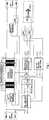
In der Zeichnung ist der Erfindungsgegenstand in einem Ausführungsbeispiel dargestellt. Es zeigt:In the drawing, the subject invention is shown in one embodiment. It shows:
In der
Sind die beiden Relais (Rel1 und Rel2) in der Ruhelage, wurde Betriebsmodus 2 detektiert. Das bedeutet, dass ein hochfrequentes Signal als Betriebsspannung an den Anschlüssen anliegt und somit ein EVG vorhanden ist. Über die induktive Hochfrequenzübertragung, welche als zwei Transformatoren dargestellt ist, wird die hochfrequente Betriebsspannung abgegriffen und einer Spannungs- und Stromanpassung zugeführt (Hochfrequenz Transformation LED Treiber). Über die beiden Ausgänge der Anpassung (OUT– und OUT+) und den Relais Rel1 und Rel2 wird die angepasste Betriebsspannung als Versorgungsspannung dem Leuchtkörper, welcher aus LEDs besteht, zugeführt. Diese leuchten dann.If the two relays (Rel1 and Rel2) are in the rest position, operating mode 2 has been detected. This means that a high-frequency signal is present as operating voltage at the terminals and thus an ECG is present. About the inductive high-frequency transmission, which is shown as two transformers, the high-frequency operating voltage is tapped and supplied to a voltage and current adjustment (high-frequency transformation LED driver). Via the two outputs of the adaptation (OUT and OUT +) and the relays Rel1 and Rel2, the adjusted operating voltage is supplied as supply voltage to the luminous element, which consists of LEDs. These will light up.
Durch die induktive Spannungsübertragung sind sehr geringe Verlustleitungen realisierbar.Due to the inductive voltage transmission very low loss lines can be realized.
Stellt die Wechselspannungsidentifikation eine Wechselspannung innerhalb 90–265 Volt bei 50 oder 60 Hz fest, steuert sie die beiden Relais (Rel1 und Rel2) an, die dann beide aus der Ruhelage in die Betriebslage schalten. Dabei schalten sie die Versorgungsspannung so um, dass sie nun einer anderen Gleichrichtung (AC/DC Standard LED Treiber) an dessen Ausgängen (OUT– und OUT+) entnommen wird. Diese Gleichrichtung wird von der normalen Betriebsspannung gespeist.If the AC identification detects an AC voltage within 90-265 volts at 50 or 60 Hz, it triggers the two relays (Rel1 and Rel2), which then switch both from the rest position to the operating position. In doing so, they switch the supply voltage so that it is now taken from another rectification (AC / DC standard LED driver) at its outputs (OUT and OUT +). This rectification is powered by the normal operating voltage.
Zusätzlich schalten die beiden Relais (Rel1 und Rel2) zwei Phasenrichter (Phasen-/Nullrichter) auf die Betriebsspannung an den elektrischen Anschlüssen, welche die Aufgabe haben, eine Verpolung der Anschlüsse zu verhindern. Die beiden Phasenrichter sorgen dafür, dass am Eingang der Gleichrichtung im Betriebsmodus 1 immer eine Betriebsspannung mit gleicher Phasenlage anliegt. Sie verhindern somit eine ungewollte Beschädigung des Leuchtmittels.In addition, the two relays (Rel1 and Rel2) switch two phase rectifiers (phase / neutral rectifier) to the operating voltage at the electrical connections, which have the task of preventing reverse polarity of the connections. The two phase rectifiers ensure that at the input of the rectification in operating mode 1 there is always an operating voltage with the same phase position. They thus prevent unwanted damage to the bulb.
Zur Entstörung und zur weiteren Verhinderung von Verlustleistung ist eine Kompensation des induktiven Hochfrequenzübertragers vorgesehen (Kapazitive Kompensation). Dadurch soll eine Phasenverschiebung zwischen übertragener Spannung und dem erzeugten Stromfluss verhindert werden, die entsprechende Verlustleistungen mit sich bringen würde.For suppression and further prevention of power loss, a compensation of the inductive high-frequency transformer is provided (capacitive compensation). This is intended to prevent a phase shift between transmitted voltage and the generated current flow, which would bring about corresponding power losses.
Auf der Zeichnung ist der Erfindungsgegenstand nur beispielsweise verwirklicht. Diese ist nicht darauf beschränkt. Vielmehr sind noch andere Ausführungen und Abwandlungen denkbar. Beispielsweise könnte die Kompensation der induktiven Hochfrequenzübertragung durch andere Mittel statt kapazitive geschehen oder es können andere Leuchtkörper als LEDs verwendet werden, beispielsweise OLEDs oder Plasmaleuchten. Ebenso ist die prismenförmige Röhre nicht auf einen runden Querschnitt begrenzt. Ebenso sind eckige, ovale oder andere Querschnitte denkbar.In the drawing, the subject invention is realized only for example. This is not limited to this. Rather, other designs and modifications are conceivable. For example, the compensation of the inductive high-frequency transmission by other means instead of capacitive could happen or it can be used other than LEDs, such as OLEDs or plasma lamps. Likewise, the prismatic tube is not limited to a round cross-section. Likewise, angular, oval or other cross-sections are conceivable.
Claims (15)
Translated fromGermanPriority Applications (2)
| Application Number | Priority Date | Filing Date | Title |
|---|---|---|---|
| DE202011003952UDE202011003952U1 (en) | 2011-03-14 | 2011-03-14 | Illuminants for use in conventional sockets for fluorescent tubes |
| PCT/EP2012/001113WO2012139691A1 (en) | 2011-03-14 | 2012-03-13 | Light-emitting means for use in conventional lampholders for fluorescent tubes |
Applications Claiming Priority (1)
| Application Number | Priority Date | Filing Date | Title |
|---|---|---|---|
| DE202011003952UDE202011003952U1 (en) | 2011-03-14 | 2011-03-14 | Illuminants for use in conventional sockets for fluorescent tubes |
Publications (1)
| Publication Number | Publication Date |
|---|---|
| DE202011003952U1true DE202011003952U1 (en) | 2012-06-15 |
Family
ID=45937188
Family Applications (1)
| Application Number | Title | Priority Date | Filing Date |
|---|---|---|---|
| DE202011003952UExpired - LifetimeDE202011003952U1 (en) | 2011-03-14 | 2011-03-14 | Illuminants for use in conventional sockets for fluorescent tubes |
Country Status (2)
| Country | Link |
|---|---|
| DE (1) | DE202011003952U1 (en) |
| WO (1) | WO2012139691A1 (en) |
Cited By (2)
| Publication number | Priority date | Publication date | Assignee | Title |
|---|---|---|---|---|
| WO2015001067A1 (en)* | 2013-07-05 | 2015-01-08 | Koninklijke Philips N.V. | Connection circuit for connecting a driver device to an external power supply for driving a load, in particular an led unit |
| DE102023103807B4 (en) | 2022-04-18 | 2024-07-18 | Ledvance Gmbh | Driver for controlling an LED light engine of an LED tube |
Families Citing this family (39)
| Publication number | Priority date | Publication date | Assignee | Title |
|---|---|---|---|---|
| US9497821B2 (en) | 2005-08-08 | 2016-11-15 | Jiaxing Super Lighting Electric Appliance Co., Ltd | LED tube lamp |
| US9794990B2 (en) | 2014-09-28 | 2017-10-17 | Jiaxing Super Lighting Electric Appliance Co., Ltd. | LED tube lamp with improved compatibility with an electrical ballast |
| US9939140B2 (en) | 2014-09-28 | 2018-04-10 | Jiaxing Super Lighting Electric Appliance Co., Ltd. | LED tube lamp |
| US10021742B2 (en) | 2014-09-28 | 2018-07-10 | Jiaxing Super Lighting Electric Appliance Co., Ltd | LED tube lamp |
| US9781805B2 (en) | 2015-03-10 | 2017-10-03 | Jiaxing Super Lighting Electric Appliance Co., Ltd. | LED tube lamp |
| US11131431B2 (en) | 2014-09-28 | 2021-09-28 | Jiaxing Super Lighting Electric Appliance Co., Ltd | LED tube lamp |
| US9480109B2 (en) | 2014-10-14 | 2016-10-25 | Jiaxing Super Lighting Electric Appliance Co., Lti | Power source module for LED lamp |
| KR102296556B1 (en) | 2013-09-25 | 2021-09-02 | 실리콘 힐 비.브이. | Led lighting system |
| CN103792217B (en)* | 2013-11-20 | 2016-05-18 | 何赛灵 | Based on coffee concentration detection system and the method for LED induced fluorescence spectrum |
| US11480305B2 (en) | 2014-09-25 | 2022-10-25 | Jiaxing Super Lighting Electric Appliance Co., Ltd. | LED tube lamp |
| US10054271B2 (en) | 2015-03-10 | 2018-08-21 | Jiaxing Super Lighting Electric Appliance Co., Ltd. | LED tube lamp |
| US9795001B2 (en) | 2014-09-28 | 2017-10-17 | Jiaxing Super Lighting Electric Appliance Co., Ltd. | LED tube lamp with overcurrent and/or overvoltage protection capabilities |
| US9756698B2 (en) | 2014-09-28 | 2017-09-05 | Jiaxing Super Lighting Electric Appliance Co., Ltd. | LED tube lamp with two operating modes compatible with electrical ballasts |
| US10560989B2 (en) | 2014-09-28 | 2020-02-11 | Jiaxing Super Lighting Electric Appliance Co., Ltd | LED tube lamp |
| US9775215B2 (en) | 2014-09-28 | 2017-09-26 | Jiaxing Super Lighting Electric Appliance Co., Ltd. | LED tube lamp with operating modes compatible with electrical ballasts |
| US10845008B2 (en) | 2014-09-28 | 2020-11-24 | Zhejiang Super Lighting Electric Appliance Co., Ltd. | LED filament and LED light bulb |
| US9689536B2 (en) | 2015-03-10 | 2017-06-27 | Jiaxing Super Lighting Electric Appliance Co., Ltd. | LED tube lamp |
| CN112197181A (en) | 2014-09-28 | 2021-01-08 | 嘉兴山蒲照明电器有限公司 | LED straight lamp |
| US10208898B2 (en) | 2015-04-29 | 2019-02-19 | Jiaxing Super Lighting Electric Appliance Co., Ltd. | LED tube lamp with operating modes compatible with electrical ballasts |
| US10514134B2 (en) | 2014-12-05 | 2019-12-24 | Jiaxing Super Lighting Electric Appliance Co., Ltd | LED tube lamp |
| US9860959B2 (en) | 2015-02-15 | 2018-01-02 | Jiaxing Super Lighting Electric Appliance Co., Ltd. | LED tube lamp compatible with different sources of external driving signal |
| US9897265B2 (en) | 2015-03-10 | 2018-02-20 | Jiaxing Super Lighting Electric Appliance Co., Ltd. | LED tube lamp having LED light strip |
| US11519565B2 (en) | 2015-03-10 | 2022-12-06 | Jiaxing Super Lighting Electric Appliance Co., Ltd | LED lamp and its power source module |
| US9867239B2 (en) | 2015-03-10 | 2018-01-09 | Jiaxing Super Lighting Electric Appliance Co., Ltd. | Light emiting diode (LED) tube lamp capable of adapting to different driving environments |
| US9903577B2 (en) | 2015-03-10 | 2018-02-27 | Jiaxing Super Lighting Electric Appliance Co., Ltd. | LED tube lamp including light strip including a pad and an opening formed on the pad |
| US9826585B2 (en) | 2015-03-10 | 2017-11-21 | Jiaxing Super Lighting Electric Appliance Co., Ltd. | LED tube lamp |
| US10197225B2 (en) | 2015-03-10 | 2019-02-05 | Jiaxing Super Lighting Electric Appliance Co., Ltd. | LED tube lamp |
| US11028973B2 (en) | 2015-03-10 | 2021-06-08 | Jiaxing Super Lighting Electric Appliance Co., Ltd. | Led tube lamp |
| US9801240B2 (en) | 2015-03-10 | 2017-10-24 | Jiaxing Super Lighting Electric Appliance Co., Ltd. | Light emitting diode (LED) tube lamp |
| US9750096B2 (en) | 2015-03-25 | 2017-08-29 | Jiaxing Super Lighting Electric Appliance Co., Ltd. | Dual-Mode LED tube lamp |
| NL2014525B1 (en)* | 2015-03-26 | 2017-01-06 | Silicon Hill Bv | Led lighting system. |
| WO2016151125A1 (en)* | 2015-03-26 | 2016-09-29 | Silicon Hill B.V. | Led lighting system |
| US9913336B2 (en) | 2015-04-03 | 2018-03-06 | Jiaxing Super Lighting Electric Appliance Co., Ltd. | Light emiting diode (LED) tube lamp compatible with different ballasts providing external driving signal |
| US10070498B2 (en) | 2015-04-14 | 2018-09-04 | Jiaxing Super Lighting Electric Appliance Co., Ltd. | LED tube lamp with improved compatibility with electrical ballasts |
| US9841174B2 (en) | 2015-04-29 | 2017-12-12 | Jiaxing Super Lighting Electric Appliance Co., Ltd. | LED tube lamp |
| GB2541537B (en)* | 2015-07-20 | 2018-03-28 | Jiaxing Super Lighting Electric Appliance Co Ltd | LED tube lamp with two operating modes compatible with electrical ballasts |
| US11035526B2 (en) | 2015-12-09 | 2021-06-15 | Jiaxing Super Lighting Electric Appliance Co., Ltd. | LED tube lamp |
| EP3240367A1 (en) | 2016-04-29 | 2017-11-01 | Silicon Hill B.V. | Ballast independent retrofit led lamp with flicker reduction circuitry |
| JP6731549B2 (en) | 2016-10-28 | 2020-07-29 | シグニファイ ホールディング ビー ヴィSignify Holding B.V. | Lighting monitoring |
Family Cites Families (3)
| Publication number | Priority date | Publication date | Assignee | Title |
|---|---|---|---|---|
| US7049761B2 (en)* | 2000-02-11 | 2006-05-23 | Altair Engineering, Inc. | Light tube and power supply circuit |
| KR100891740B1 (en)* | 2007-11-13 | 2009-04-03 | 김철 | LED lamp connection device of fluorescent lamp |
| DE102010003266A1 (en)* | 2010-03-25 | 2011-09-29 | Osram Gesellschaft mit beschränkter Haftung | Circuit arrangement for operating e.g. rod-shaped retrofit lamp, at electronic ballast for fluorescent lamp, has light source connected to output of full wave rectifier and resistors connected with input terminals of retrofit lamp |
- 2011
- 2011-03-14DEDE202011003952Upatent/DE202011003952U1/ennot_activeExpired - Lifetime
- 2012
- 2012-03-13WOPCT/EP2012/001113patent/WO2012139691A1/enactiveApplication Filing
Cited By (3)
| Publication number | Priority date | Publication date | Assignee | Title |
|---|---|---|---|---|
| WO2015001067A1 (en)* | 2013-07-05 | 2015-01-08 | Koninklijke Philips N.V. | Connection circuit for connecting a driver device to an external power supply for driving a load, in particular an led unit |
| US9426849B2 (en) | 2013-07-05 | 2016-08-23 | Koninklijke Philips N.V. | Connection circuit for connecting a driver to an external power supply for driving an LED unit |
| DE102023103807B4 (en) | 2022-04-18 | 2024-07-18 | Ledvance Gmbh | Driver for controlling an LED light engine of an LED tube |
Also Published As
| Publication number | Publication date |
|---|---|
| WO2012139691A1 (en) | 2012-10-18 |
Similar Documents
| Publication | Publication Date | Title |
|---|---|---|
| DE202011003952U1 (en) | Illuminants for use in conventional sockets for fluorescent tubes | |
| WO2012028396A1 (en) | Circuit assembly and method for operating at least one led | |
| EP2596682B1 (en) | Control apparatus and method for detecting a type of load | |
| EP1755363B1 (en) | Circuit for operating at least one fluorescent discharge lamp and at least one LED | |
| DE102007036438A1 (en) | Method for controlling a universal dimmer | |
| EP1740020A2 (en) | Circuit and method for operating at least one Led and at least one discharge lamp | |
| AT517946B1 (en) | PROCESS, OPERATING DEVICE AND LIGHTING SYSTEM | |
| EP2368410B1 (en) | Method and operating device for operating a lighting means using regulated current | |
| DE20114623U1 (en) | Distal adapter for T5 fluorescent lamps with retrofit ECG | |
| EP1836882B1 (en) | Electronic ballast | |
| DE202012100373U1 (en) | fluorescent tube | |
| DE102013108775A1 (en) | Circuit arrangement for an LED tube and LED tube with a circuit arrangement | |
| EP1243165B1 (en) | Circuit for operating a gas discharge lamp | |
| DE19834035B4 (en) | Compact low-voltage energy-saving lamp | |
| DE112012001080B4 (en) | Change of operation of an operating device for lamps | |
| DE10127135B4 (en) | Dimmable electronic ballast | |
| EP2263421A1 (en) | Detection of the assignment of a terminal of an operating device for illumination means | |
| DE202006017228U1 (en) | Electronic ballast for operating at least one discharge lamp, especially a fluorescent lamp, and lamp system has at least one separate holding unit to receive the discharge lamp | |
| DE102016106474B3 (en) | Shunt module and method for providing the necessary operating current for a dimmer | |
| DE10203356B4 (en) | Ballast for cold cathode fluorescent lamps | |
| AT511911B1 (en) | SYSTEM FOR CONTROLLING AND OPERATING FLUORESCENT LAMPS | |
| DE202011050150U1 (en) | Illuminant comprising one or more light-emitting diodes, arrangement with the light bulb and emergency light with the arrangement | |
| WO2013092586A2 (en) | Operation of lighting means | |
| DE202010005424U1 (en) | A drive switching element with light emitting diodes | |
| DE19923083A1 (en) | Adapter for low pressure discharge lamps has bridge circuit outputs connected to primary coil winding and to first secondary coil, second output or negative pole to second secondary coil |
Legal Events
| Date | Code | Title | Description |
|---|---|---|---|
| R082 | Change of representative | Representative=s name:BUSE MENTZEL LUDEWIG PATENTANWALTSKANZLEI, DE Representative=s name:BUSE, MENTZEL, LUDEWIG, DE | |
| R207 | Utility model specification | Effective date:20120809 | |
| R156 | Lapse of ip right after 3 years | ||
| R156 | Lapse of ip right after 3 years | Effective date:20141001 |