DE202011002608U1 - tripod head - Google Patents
tripod headDownload PDFInfo
- Publication number
- DE202011002608U1 DE202011002608U1DE202011002608UDE202011002608UDE202011002608U1DE 202011002608 U1DE202011002608 U1DE 202011002608U1DE 202011002608 UDE202011002608 UDE 202011002608UDE 202011002608 UDE202011002608 UDE 202011002608UDE 202011002608 U1DE202011002608 U1DE 202011002608U1
- Authority
- DE
- Germany
- Prior art keywords
- damping
- damping element
- parts
- tripod head
- head according
- Prior art date
- Legal status (The legal status is an assumption and is not a legal conclusion. Google has not performed a legal analysis and makes no representation as to the accuracy of the status listed.)
- Expired - Lifetime
Links
- 238000013016dampingMethods0.000claimsabstractdescription134
- 230000008016vaporizationEffects0.000claims1
- 238000004519manufacturing processMethods0.000description7
- 238000000034methodMethods0.000description5
- 230000005540biological transmissionEffects0.000description3
- 239000000463materialSubstances0.000description3
- 239000002184metalSubstances0.000description3
- 238000000465mouldingMethods0.000description3
- 229920002545silicone oilPolymers0.000description3
- 239000012530fluidSubstances0.000description2
- 238000001746injection mouldingMethods0.000description2
- 238000010025steamingMethods0.000description2
- BUHVIAUBTBOHAG-FOYDDCNASA-N(2r,3r,4s,5r)-2-[6-[[2-(3,5-dimethoxyphenyl)-2-(2-methylphenyl)ethyl]amino]purin-9-yl]-5-(hydroxymethyl)oxolane-3,4-diolChemical compoundCOC1=CC(OC)=CC(C(CNC=2C=3N=CN(C=3N=CN=2)[C@H]2[C@@H]([C@H](O)[C@@H](CO)O2)O)C=2C(=CC=CC=2)C)=C1BUHVIAUBTBOHAG-FOYDDCNASA-N0.000description1
- 238000005452bendingMethods0.000description1
- 230000015572biosynthetic processEffects0.000description1
- 238000005266castingMethods0.000description1
- 230000007423decreaseEffects0.000description1
- 238000013461designMethods0.000description1
- 238000011161developmentMethods0.000description1
- 230000018109developmental processEffects0.000description1
- 230000002349favourable effectEffects0.000description1
- 239000004519greaseSubstances0.000description1
- 238000009434installationMethods0.000description1
- 238000012986modificationMethods0.000description1
- 230000004048modificationEffects0.000description1
- 229920001296polysiloxanePolymers0.000description1
- 238000003825pressingMethods0.000description1
- 239000000243solutionSubstances0.000description1
- 125000006850spacer groupChemical group0.000description1
- 238000013519translationMethods0.000description1
Images


Classifications
- G—PHYSICS
- G03—PHOTOGRAPHY; CINEMATOGRAPHY; ANALOGOUS TECHNIQUES USING WAVES OTHER THAN OPTICAL WAVES; ELECTROGRAPHY; HOLOGRAPHY
- G03B—APPARATUS OR ARRANGEMENTS FOR TAKING PHOTOGRAPHS OR FOR PROJECTING OR VIEWING THEM; APPARATUS OR ARRANGEMENTS EMPLOYING ANALOGOUS TECHNIQUES USING WAVES OTHER THAN OPTICAL WAVES; ACCESSORIES THEREFOR
- G03B17/00—Details of cameras or camera bodies; Accessories therefor
- G03B17/56—Accessories
- G03B17/561—Support related camera accessories
- F—MECHANICAL ENGINEERING; LIGHTING; HEATING; WEAPONS; BLASTING
- F16—ENGINEERING ELEMENTS AND UNITS; GENERAL MEASURES FOR PRODUCING AND MAINTAINING EFFECTIVE FUNCTIONING OF MACHINES OR INSTALLATIONS; THERMAL INSULATION IN GENERAL
- F16F—SPRINGS; SHOCK-ABSORBERS; MEANS FOR DAMPING VIBRATION
- F16F13/00—Units comprising springs of the non-fluid type as well as vibration-dampers, shock-absorbers, or fluid springs
- F—MECHANICAL ENGINEERING; LIGHTING; HEATING; WEAPONS; BLASTING
- F16—ENGINEERING ELEMENTS AND UNITS; GENERAL MEASURES FOR PRODUCING AND MAINTAINING EFFECTIVE FUNCTIONING OF MACHINES OR INSTALLATIONS; THERMAL INSULATION IN GENERAL
- F16F—SPRINGS; SHOCK-ABSORBERS; MEANS FOR DAMPING VIBRATION
- F16F15/00—Suppression of vibrations in systems; Means or arrangements for avoiding or reducing out-of-balance forces, e.g. due to motion
- F16F15/10—Suppression of vibrations in rotating systems by making use of members moving with the system
- F16F15/12—Suppression of vibrations in rotating systems by making use of members moving with the system using elastic members or friction-damping members, e.g. between a rotating shaft and a gyratory mass mounted thereon
- F16F15/121—Suppression of vibrations in rotating systems by making use of members moving with the system using elastic members or friction-damping members, e.g. between a rotating shaft and a gyratory mass mounted thereon using springs as elastic members, e.g. metallic springs
- F16F15/1215—Leaf springs, e.g. radially extending
- F—MECHANICAL ENGINEERING; LIGHTING; HEATING; WEAPONS; BLASTING
- F16—ENGINEERING ELEMENTS AND UNITS; GENERAL MEASURES FOR PRODUCING AND MAINTAINING EFFECTIVE FUNCTIONING OF MACHINES OR INSTALLATIONS; THERMAL INSULATION IN GENERAL
- F16F—SPRINGS; SHOCK-ABSORBERS; MEANS FOR DAMPING VIBRATION
- F16F9/00—Springs, vibration-dampers, shock-absorbers, or similarly-constructed movement-dampers using a fluid or the equivalent as damping medium
- F16F9/10—Springs, vibration-dampers, shock-absorbers, or similarly-constructed movement-dampers using a fluid or the equivalent as damping medium using liquid only; using a fluid of which the nature is immaterial
- F16F9/12—Devices with one or more rotary vanes turning in the fluid any throttling effect being immaterial, i.e. damping by viscous shear effect only
- F—MECHANICAL ENGINEERING; LIGHTING; HEATING; WEAPONS; BLASTING
- F16—ENGINEERING ELEMENTS AND UNITS; GENERAL MEASURES FOR PRODUCING AND MAINTAINING EFFECTIVE FUNCTIONING OF MACHINES OR INSTALLATIONS; THERMAL INSULATION IN GENERAL
- F16M—FRAMES, CASINGS OR BEDS OF ENGINES, MACHINES OR APPARATUS, NOT SPECIFIC TO ENGINES, MACHINES OR APPARATUS PROVIDED FOR ELSEWHERE; STANDS; SUPPORTS
- F16M11/00—Stands or trestles as supports for apparatus or articles placed thereon ; Stands for scientific apparatus such as gravitational force meters
- F16M11/02—Heads
- F16M11/04—Means for attachment of apparatus; Means allowing adjustment of the apparatus relatively to the stand
- F16M11/041—Allowing quick release of the apparatus
- F—MECHANICAL ENGINEERING; LIGHTING; HEATING; WEAPONS; BLASTING
- F16—ENGINEERING ELEMENTS AND UNITS; GENERAL MEASURES FOR PRODUCING AND MAINTAINING EFFECTIVE FUNCTIONING OF MACHINES OR INSTALLATIONS; THERMAL INSULATION IN GENERAL
- F16M—FRAMES, CASINGS OR BEDS OF ENGINES, MACHINES OR APPARATUS, NOT SPECIFIC TO ENGINES, MACHINES OR APPARATUS PROVIDED FOR ELSEWHERE; STANDS; SUPPORTS
- F16M11/00—Stands or trestles as supports for apparatus or articles placed thereon ; Stands for scientific apparatus such as gravitational force meters
- F16M11/02—Heads
- F16M11/04—Means for attachment of apparatus; Means allowing adjustment of the apparatus relatively to the stand
- F16M11/06—Means for attachment of apparatus; Means allowing adjustment of the apparatus relatively to the stand allowing pivoting
- F—MECHANICAL ENGINEERING; LIGHTING; HEATING; WEAPONS; BLASTING
- F16—ENGINEERING ELEMENTS AND UNITS; GENERAL MEASURES FOR PRODUCING AND MAINTAINING EFFECTIVE FUNCTIONING OF MACHINES OR INSTALLATIONS; THERMAL INSULATION IN GENERAL
- F16M—FRAMES, CASINGS OR BEDS OF ENGINES, MACHINES OR APPARATUS, NOT SPECIFIC TO ENGINES, MACHINES OR APPARATUS PROVIDED FOR ELSEWHERE; STANDS; SUPPORTS
- F16M11/00—Stands or trestles as supports for apparatus or articles placed thereon ; Stands for scientific apparatus such as gravitational force meters
- F16M11/02—Heads
- F16M11/16—Details concerning attachment of head-supporting legs, with or without actuation of locking members thereof
- F—MECHANICAL ENGINEERING; LIGHTING; HEATING; WEAPONS; BLASTING
- F16—ENGINEERING ELEMENTS AND UNITS; GENERAL MEASURES FOR PRODUCING AND MAINTAINING EFFECTIVE FUNCTIONING OF MACHINES OR INSTALLATIONS; THERMAL INSULATION IN GENERAL
- F16F—SPRINGS; SHOCK-ABSORBERS; MEANS FOR DAMPING VIBRATION
- F16F15/00—Suppression of vibrations in systems; Means or arrangements for avoiding or reducing out-of-balance forces, e.g. due to motion
- F16F15/10—Suppression of vibrations in rotating systems by making use of members moving with the system
- F16F15/16—Suppression of vibrations in rotating systems by making use of members moving with the system using a fluid or pasty material
- F—MECHANICAL ENGINEERING; LIGHTING; HEATING; WEAPONS; BLASTING
- F16—ENGINEERING ELEMENTS AND UNITS; GENERAL MEASURES FOR PRODUCING AND MAINTAINING EFFECTIVE FUNCTIONING OF MACHINES OR INSTALLATIONS; THERMAL INSULATION IN GENERAL
- F16F—SPRINGS; SHOCK-ABSORBERS; MEANS FOR DAMPING VIBRATION
- F16F7/00—Vibration-dampers; Shock-absorbers
- F16F7/02—Vibration-dampers; Shock-absorbers with relatively-rotatable friction surfaces that are pressed together
- F16F7/06—Vibration-dampers; Shock-absorbers with relatively-rotatable friction surfaces that are pressed together in a direction perpendicular or inclined to the axis of rotation
- F—MECHANICAL ENGINEERING; LIGHTING; HEATING; WEAPONS; BLASTING
- F16—ENGINEERING ELEMENTS AND UNITS; GENERAL MEASURES FOR PRODUCING AND MAINTAINING EFFECTIVE FUNCTIONING OF MACHINES OR INSTALLATIONS; THERMAL INSULATION IN GENERAL
- F16F—SPRINGS; SHOCK-ABSORBERS; MEANS FOR DAMPING VIBRATION
- F16F9/00—Springs, vibration-dampers, shock-absorbers, or similarly-constructed movement-dampers using a fluid or the equivalent as damping medium
- F16F9/30—Springs, vibration-dampers, shock-absorbers, or similarly-constructed movement-dampers using a fluid or the equivalent as damping medium with solid or semi-solid material, e.g. pasty masses, as damping medium
- F—MECHANICAL ENGINEERING; LIGHTING; HEATING; WEAPONS; BLASTING
- F16—ENGINEERING ELEMENTS AND UNITS; GENERAL MEASURES FOR PRODUCING AND MAINTAINING EFFECTIVE FUNCTIONING OF MACHINES OR INSTALLATIONS; THERMAL INSULATION IN GENERAL
- F16M—FRAMES, CASINGS OR BEDS OF ENGINES, MACHINES OR APPARATUS, NOT SPECIFIC TO ENGINES, MACHINES OR APPARATUS PROVIDED FOR ELSEWHERE; STANDS; SUPPORTS
- F16M11/00—Stands or trestles as supports for apparatus or articles placed thereon ; Stands for scientific apparatus such as gravitational force meters
- F16M11/02—Heads
- F16M11/04—Means for attachment of apparatus; Means allowing adjustment of the apparatus relatively to the stand
- F16M11/06—Means for attachment of apparatus; Means allowing adjustment of the apparatus relatively to the stand allowing pivoting
- F16M11/08—Means for attachment of apparatus; Means allowing adjustment of the apparatus relatively to the stand allowing pivoting around a vertical axis, e.g. panoramic heads
- F—MECHANICAL ENGINEERING; LIGHTING; HEATING; WEAPONS; BLASTING
- F16—ENGINEERING ELEMENTS AND UNITS; GENERAL MEASURES FOR PRODUCING AND MAINTAINING EFFECTIVE FUNCTIONING OF MACHINES OR INSTALLATIONS; THERMAL INSULATION IN GENERAL
- F16M—FRAMES, CASINGS OR BEDS OF ENGINES, MACHINES OR APPARATUS, NOT SPECIFIC TO ENGINES, MACHINES OR APPARATUS PROVIDED FOR ELSEWHERE; STANDS; SUPPORTS
- F16M11/00—Stands or trestles as supports for apparatus or articles placed thereon ; Stands for scientific apparatus such as gravitational force meters
- F16M11/02—Heads
- F16M11/04—Means for attachment of apparatus; Means allowing adjustment of the apparatus relatively to the stand
- F16M11/06—Means for attachment of apparatus; Means allowing adjustment of the apparatus relatively to the stand allowing pivoting
- F16M11/10—Means for attachment of apparatus; Means allowing adjustment of the apparatus relatively to the stand allowing pivoting around a horizontal axis
- F—MECHANICAL ENGINEERING; LIGHTING; HEATING; WEAPONS; BLASTING
- F16—ENGINEERING ELEMENTS AND UNITS; GENERAL MEASURES FOR PRODUCING AND MAINTAINING EFFECTIVE FUNCTIONING OF MACHINES OR INSTALLATIONS; THERMAL INSULATION IN GENERAL
- F16M—FRAMES, CASINGS OR BEDS OF ENGINES, MACHINES OR APPARATUS, NOT SPECIFIC TO ENGINES, MACHINES OR APPARATUS PROVIDED FOR ELSEWHERE; STANDS; SUPPORTS
- F16M11/00—Stands or trestles as supports for apparatus or articles placed thereon ; Stands for scientific apparatus such as gravitational force meters
- F16M11/20—Undercarriages with or without wheels
- F16M11/24—Undercarriages with or without wheels changeable in height or length of legs, also for transport only, e.g. by means of tubes screwed into each other
- F16M11/26—Undercarriages with or without wheels changeable in height or length of legs, also for transport only, e.g. by means of tubes screwed into each other by telescoping, with or without folding
- F16M11/32—Undercarriages for supports with three or more telescoping legs
- F—MECHANICAL ENGINEERING; LIGHTING; HEATING; WEAPONS; BLASTING
- F16—ENGINEERING ELEMENTS AND UNITS; GENERAL MEASURES FOR PRODUCING AND MAINTAINING EFFECTIVE FUNCTIONING OF MACHINES OR INSTALLATIONS; THERMAL INSULATION IN GENERAL
- F16M—FRAMES, CASINGS OR BEDS OF ENGINES, MACHINES OR APPARATUS, NOT SPECIFIC TO ENGINES, MACHINES OR APPARATUS PROVIDED FOR ELSEWHERE; STANDS; SUPPORTS
- F16M13/00—Other supports for positioning apparatus or articles; Means for steadying hand-held apparatus or articles
- F16M13/04—Other supports for positioning apparatus or articles; Means for steadying hand-held apparatus or articles for supporting on, or holding steady relative to, a person, e.g. by chains, e.g. rifle butt or pistol grip supports, supports attached to the chest or head
- F—MECHANICAL ENGINEERING; LIGHTING; HEATING; WEAPONS; BLASTING
- F16—ENGINEERING ELEMENTS AND UNITS; GENERAL MEASURES FOR PRODUCING AND MAINTAINING EFFECTIVE FUNCTIONING OF MACHINES OR INSTALLATIONS; THERMAL INSULATION IN GENERAL
- F16M—FRAMES, CASINGS OR BEDS OF ENGINES, MACHINES OR APPARATUS, NOT SPECIFIC TO ENGINES, MACHINES OR APPARATUS PROVIDED FOR ELSEWHERE; STANDS; SUPPORTS
- F16M2200/00—Details of stands or supports
- F16M2200/04—Balancing means
- F16M2200/041—Balancing means for balancing rotational movement of the head
- F—MECHANICAL ENGINEERING; LIGHTING; HEATING; WEAPONS; BLASTING
- F16—ENGINEERING ELEMENTS AND UNITS; GENERAL MEASURES FOR PRODUCING AND MAINTAINING EFFECTIVE FUNCTIONING OF MACHINES OR INSTALLATIONS; THERMAL INSULATION IN GENERAL
- F16M—FRAMES, CASINGS OR BEDS OF ENGINES, MACHINES OR APPARATUS, NOT SPECIFIC TO ENGINES, MACHINES OR APPARATUS PROVIDED FOR ELSEWHERE; STANDS; SUPPORTS
- F16M2200/00—Details of stands or supports
- F16M2200/04—Balancing means
- F16M2200/047—Balancing means for balancing translational movement of the head
Landscapes
- Engineering & Computer Science (AREA)
- General Engineering & Computer Science (AREA)
- Mechanical Engineering (AREA)
- Physics & Mathematics (AREA)
- General Physics & Mathematics (AREA)
- Acoustics & Sound (AREA)
- Aviation & Aerospace Engineering (AREA)
- Vibration Prevention Devices (AREA)
- Accessories Of Cameras (AREA)
- Fluid-Damping Devices (AREA)
- Studio Devices (AREA)
- Pivots And Pivotal Connections (AREA)
Abstract
Translated fromGermanDescription
Translated fromGermanDie vorliegende Erfindung betrifft einen Stativkopf und insbesondere einen solchen Stativkopf, der zur Aufnahme einer Film- und Fernsehkamera geeignet ist. Insbesondere betrifft die vorliegende Erfindung dabei eine Dämpfungseinrichtung zum Dämpfen der Schwenkbewegung eines ersten Körpers des Stativkopfs relativ zu einem zweiten Körper des Stativkopfs und hierbei insbesondere eine hydraulische Dämpfungseinrichtung.The present invention relates to a tripod head and in particular to such a tripod head which is suitable for receiving a film and television camera. In particular, the present invention relates to a damping device for damping the pivotal movement of a first body of the tripod head relative to a second body of the tripod head, and in particular a hydraulic damping device.
Eine derartige hydraulische Dampfungseinrichtung ist beispielsweise aus der
Darüber hinaus sind für die Einstellbarkeit der Dämpfungskraft viele in Axialrichtung nebeneinander angeordnete Dämpfungsglieder erforderlich, die einen erheblichen axialen Bauraum einnehmen.In addition, many damping elements arranged next to one another in the axial direction are required for the adjustability of the damping force, which occupy considerable axial space.
Ferner ist aus der
Eine Möglichkeit, um bei einer Dämpfungseinrichtung, wie sie in der
Angesichts dieser Ausführungen besteht die Aufgabe der vorliegenden Erfindung darin, einen Stativkopf mit einer hydraulischen Dämpfungseinrichtung zu schaffen, die mit geringem Materialeinsatz und Montageaufwand hergestellt werden kann, wenig Bauraum einnimmt und zugleich die Einstellbarkeit der Dämpfungskraft ermöglicht.In view of these embodiments, the object of the present invention is to provide a tripod head with a hydraulic damping device that can be produced with low material usage and assembly costs, occupies little space and at the same time allows the adjustability of the damping force.
Diese Aufgabe wird durch einen Stativkopf mit den Merkmalen des Anspruchs 1 gelöst. Vorteilhafte Weiterbildungen der Erfindung finden sich in den Unteransprüchen.This object is achieved by a tripod head with the features of claim 1. Advantageous developments of the invention can be found in the subclaims.
Der Grundgedanke der vorliegenden Erfindung liegt darin (nur) eines der Dämpfungselemente, die kammartige ineinander greifen, mehrteilig zu gestalten und die Teile in Radialrichtung nebeneinander anzuordnen. Indem die Teile separat festlegbar sind, ist die Dämpfungskraft einstellbar. Dennoch wird in Axialrichtung kaum mehr Bauraum benötigt, da die Teile in Radialrichtung nebeneinander liegen. Darüber hinaus greifen die Teile des einen Dampfungselements in dasselbe gegenüberliegende Dämpfungselement ein, so dass hierfür nur ein Teil (insgesamt drei Teile) benötigt wird (werden).The basic idea of the present invention is (only) one of the damping elements, the comb-like mesh, to make multi-part and arrange the parts in the radial direction next to each other. By the parts can be fixed separately, the damping force is adjustable. Nevertheless, hardly more space is required in the axial direction, since the parts are adjacent to each other in the radial direction. In addition, the parts of the one damping element engage in the same opposite damping element, so that only a part (a total of three parts) is required for this purpose.
Dementsprechend umfasst ein Stativkopf gemäß der vorliegenden Erfindung einen ersten und einen zweiten Korper, wobei der erste Körper um wenigstens eine Achse relativ zu dem zweiten Korper verschwenkbar ist. Derartige Stativköpfe ermoglichen in der Regel eine Verschwenkung der montierten Film- und Fernsehkamera um wenigstens zwei Achsen, eine Horizontal- und eine Vertikalachse. Solche Stativköpfe sind meist aus einem Grundkörper zur Befestigung an dem Stativ, einem Zwischenkörper und einer Aufnahme zur Befestigung der Film- und Fernsehkamera aufgebaut. Dabei ist der Zwischenkörper relativ zum Grundkörper um eine Vertikalachse schwenkbar sowie die Aufnahme relativ zum Zwischenkörper um eine Horizontalachse. Die erfindungsgemaße Dämpfungseinrichtung kann zur Dampfung der Schwenkbewegung um die horizontale und/oder die vertikale Achse verwendet werden. Die Dämpfungseinrichtung kann dementsprechend die Schwenkbewegung des Zwischenkorpers relativ zum Grundkörper bzw. die Schwenkbewegung der Aufnahme relativ zum Zwischenkörper dämpfen. Dabei dient die erfindungsgemäße Dämpfungseinrichtung dem Dämpfen der Schwenkbewegung, um die Kamera gleichmäßig und kontrolliert führen zu können. Die Dämpfungseinrichtung umfasst ein erstes und ein zweites Dämpfungselement. Das erste Dämpfungselement ist an dem ersten Körper festgelegt, während das zweite Dämpfungselement, wie es später näher ausgeführt wird, wahlweise an dem zweiten Körper festgelegt werden kann, um die Dämpfungseinrichtung zu aktivieren und die Dämpfungskraft einzustellen. Beide Dämpfungselemente weisen jeweils mehrere zur Schwenkachse konzentrisch angeordnete ringförmige Rippen auf, die in zwischen den Rippen des jeweils anderen Dämpfungselements gebildete Zwischenräume greifen. Zwischen den Rippen der Dämpfungselemente ist ein Dämpfungsmedium bzw. Dämpfungsfluid, z. B. eine Dampfungsflüssigkeit, z. B. Silikonöl oder -fett vorgesehen. Erfindungsgemäß ist das zweite Dämpfungselement aus wenigstens zwei separaten Teilen aufgebaut, die nicht miteinander verbunden sind. Die zwei Teile weisen jeweils mehrere konzentrisch angeordnete ringförmige Rippen auf, die in zwischen den Rippen des ersten Dämpfungselements gebildete Zwischenräume greifen. Diese wenigstens zwei Teile des zweiten Dämpfungselements sind unabhängig voneinander an dem zweiten Körper festlegbar, um dadurch die Dämpfungskraft einstellen zu konnen. So lassen sich beispielsweise bei zwei Teilen vier Dämpfungsstufen realisieren. Ist keines der beiden Teile des zweiten Dämpfungselements am zweiten Körper festgelegt, so findet keine Dämpfung statt (Stufe 0). Wird nur der erste Teil an dem zweiten Körper festgelegt, ergibt sich eine erste Dämpfungskraft (Stufe 1). Wird nur der zweite Teil an dem zweiten Korper festgelegt und unterscheidet sich die durch die jeweiligen Teile zur Verfügung gestellte Dämpfungskraft, ergibt sich dadurch eine dritte Dämpfungskraft (Stufe 2). Sind schließlich beide Teile am zweiten Körper festgelegt, ergibt sich die höchste Dämpfungskraft (Stufe 3). Ist das zweite Dämpfungselement aus mehr als zwei Teilen gebildet, so ergibt sich die Möglichkeit noch weitere Dampfungsstufen zu integrieren. Da die Rippen der zwei separaten Teile des zweiten Dämpfungselements in die Zwischenräume der Rippen desselben ersten Dämpfungselements greifen und die Teile radial nebeneinander bzw. konzentrisch zueinander angeordnet sind, wird die Einstellbarkeit der Dämpfungskraft ermöglicht ohne den erforderlichen Bauraum in Axialrichtung zu vergrößern. Darüber hinaus besteht die Dämpfungseinrichtung im Wesentlichen aus nur drei Teilen und ist daher einfach zu montieren und unter geringem Materialeinsatz herstellbar.Accordingly, a tripod head according to the present invention comprises a first and a second body, wherein the first body is pivotable about at least one axis relative to the second body. Such tripod heads usually allow a pivoting of the mounted film and television camera by at least two axes, a horizontal and a vertical axis. Such tripod heads are usually constructed of a base body for attachment to the tripod, an intermediate body and a receptacle for mounting the film and television camera. In this case, the intermediate body is pivotable relative to the base body about a vertical axis and the receptacle relative to the intermediate body about a horizontal axis. The inventive damping device can for Damping of the pivoting movement about the horizontal and / or the vertical axis can be used. The damping device can accordingly attenuate the pivoting movement of the intermediate body relative to the base body or the pivoting movement of the holder relative to the intermediate body. In this case, the damping device according to the invention serves to damp the pivoting movement in order to be able to guide the camera uniformly and in a controlled manner. The damping device comprises a first and a second damping element. The first damping element is fixed to the first body, while the second damping element, as will be explained later, can optionally be fixed to the second body to activate the damping device and adjust the damping force. Both damping elements each have a plurality of concentric to the pivot axis arranged annular ribs which engage in intermediate spaces formed between the ribs of the respective other damping element. Between the ribs of the damping elements is a damping medium or damping fluid, for. B. a damping fluid, for. As silicone oil or fat provided. According to the invention, the second damping element is constructed from at least two separate parts which are not connected to each other. The two parts each have a plurality of concentrically arranged annular ribs which engage in intermediate spaces formed between the ribs of the first damping element. These at least two parts of the second damping element are independently fixable to the second body to thereby adjust the damping force. For example, four damping levels can be achieved with two parts. If neither of the two parts of the second damping element is fixed to the second body, no damping takes place (level 0). If only the first part is fixed to the second body, a first damping force results (stage 1). If only the second part is fixed to the second body and the damping force provided by the respective parts is different, this results in a third damping force (step 2). Finally, when both parts are fixed to the second body, the highest damping force (step 3) results. If the second damping element is formed from more than two parts, then there is the possibility of integrating further damping stages. Since the ribs of the two separate parts of the second damping element engage in the interstices of the ribs of the same first damping element and the parts are arranged radially adjacent to each other or concentric with each other, the adjustability of the damping force is made possible without increasing the required space in the axial direction. In addition, the damping device consists essentially of only three parts and is therefore easy to assemble and can be produced with little use of materials.
Vorteilhafterweise wird die Festlegung der zwei separaten Teile dadurch erzielt, dass die separaten Teile des zweiten Dämpfungselements jeweils wenigstens eine Aussparung aufweisen, in die jeweils wenigstens ein Eingriffelement einrückbar ist. Dabei kann es von Vorteil sein für jeden der separaten Teile mehrere Aussparungen vorzusehen, in die jeweils wenigstens ein Eingriffelement einrückbar ist. Dadurch kann eine hohe Drehmomentübertragung vom zweiten Körper auf den jeweiligen Teil gewährleistet werden.Advantageously, the fixing of the two separate parts is achieved in that the separate parts of the second damping element each have at least one recess, in each of which at least one engagement element is engageable. It may be advantageous for each of the separate parts to provide a plurality of recesses, in each of which at least one engagement element is engageable. As a result, a high torque transmission from the second body to the respective part can be ensured.
Dabei ist es besonders bevorzugt, dass die Eingriffelemente in Axialrichtung in die Aussparungen einrückbar sind. Da die konzentrische Anordnung der zwei separaten Teile des zweiten Dämpfungselements bereits mehr Bauraum in Radialrichtung erfordert, kann durch eine Bewegung der Eingriffelemente in Axialrichtung in die Aussparungen eine weitere Bauraumvergrößerung in Radialrichtung vermieden werden. Es ist jedoch auch denkbar, dass die Eingriffelemente in Radialrichtung in die jeweiligen Aussparungen bewegbar bzw. einrückbar sind. Hierzu konnen beispielsweise Systeme, wie sie in der
Gemäß einer bevorzugten Ausführungsform sind die Eingriffelemente in Richtung der Aussparungen vorgespannt. Mit anderen Worten werden sie, z. B. durch eine Feder, in Eingriff mit den Aussparungen beaufschlagt. Es ist jedoch gleichermaßen denkbar die Eingriffelemente in der entgegengesetzten Richtung vorzuspannen bzw. zu beaufschlagen, d. h. außer Eingriff mit den Aussparungen.According to a preferred embodiment, the engagement elements are biased in the direction of the recesses. In other words, they will, for. B. acted upon by a spring in engagement with the recesses. However, it is equally conceivable to bias the engaging elements in the opposite direction or to act on, d. H. out of engagement with the recesses.
Gemäß dieser Ausgestaltung ist es besonders bevorzugt, die Eingriffelemente als einstückigen Bestandteil einer Blattfeder auszugestalten. Dadurch kann die Vorspannung bzw. Beaufschlagung der Eingriffelemente über ein und dasselbe Element erzielt werden, das auch die Eingriffelemente bildet und das vorzugsweise als Biege- und Stanzteil ausgebildet ist. Folglich stellt diese Ausführungsform eine einfach herzustellende und mit wenigen Teilen auskommende Losung bereit. Die Blattfeder dient dabei dazu die Eingriffelemente in Richtung der Aussparungen bzw. in der entgegengesetzten Richtung vorzuspannen.According to this embodiment, it is particularly preferred to design the engagement elements as an integral part of a leaf spring. Thereby, the biasing or loading of the engagement elements can be achieved via one and the same element, which also forms the engagement elements and which is preferably formed as a bending and stamping part. Consequently, this embodiment provides an easy-to-manufacture and few-part solution. The leaf spring serves to bias the engagement elements in the direction of the recesses or in the opposite direction.
Hierfür werden die Eingriffelemente vorzugsweise aus der Ebene der Blattfeder heraus in eine aufrechte Stellung gebogen. Um eine ausreichende Drehmomentübertragung zu gewährleisten, ist es dabei bevorzugt die Eingriffelemente als flächige Laschen auszubilden, so dass eine relativ große Kontaktfläche zwischen den Eingriffelementen und den die Aussparungen begrenzenden Wänden der separaten Teile erzielt werden kann.For this purpose, the engagement elements are preferably bent out of the plane of the leaf spring in an upright position. In order to ensure a sufficient torque transmission, it is preferred to form the engagement elements as flat tabs, so that a relatively large contact area between the engagement elements and the recesses bounding walls of the separate parts can be achieved.
Darüber hinaus war es bei der Verwendung von Verzahnungen zur Festlegung der jeweiligen Dämpfungsglieder im Stand der Technik erforderlich geringe Toleranzen im Fertigungsprozess einzuhalten, um eine spielfreie Dämpfung zu gewährleisten (siehe Eingangs). Um den Fertigungsprozess diesbezüglich günstiger zu gestalten, ist von Vorteil die Eingriffelemente jeweils durch zwei bevorzugt in Umfangsrichtung der separaten Teile des zweiten Dämpfungselements beabstandete, in entgegengesetzte Richtungen geneigte Laschen auszubilden, die vorzugsweise entgegen ihrer Neigungsrichtung federnd ausgestaltet sind. Durch diese Ausgestaltung wird es möglich, dass die Eingriffelemente Montage- und Fertigungstoleranzen beim Einrücken in die Aussparungen selbst ausgleichen, so dass größere Toleranzen bei Montage und Fertigung zugelassen werden können. In addition, when using gears for fixing the respective attenuators in the prior art, it was necessary to maintain low tolerances in the manufacturing process in order to ensure backlash-free damping (see input). In order to make the manufacturing process more favorable in this regard, it is advantageous to form the engagement elements in each case by two tabs which are preferably spaced apart in the circumferential direction of the separate parts of the second damping element and which are inclined in opposite directions, which are preferably resiliently configured counter to their direction of inclination. By this configuration, it is possible that the engagement elements compensate for assembly and manufacturing tolerances when engaging in the recesses itself, so that larger tolerances can be allowed during installation and production.
Um die Bedienbarkeit des Stativkopfs zu verbessern, ist es bevorzugt eine Handhabe vorzusehen, die von einem Verwender betätigt werden kann, um die zwei separaten Teile wahlweise an dem zweiten Körper festzulegen. Bei der Handhabe kann es sich um einen Drehknopf oder einen Drehring, wie er beispielsweise in der
Um die Anzahl der für die Montage erforderlichen Teile zu verringern, ist es besonders bevorzugt das erste Dämpfungselement und/oder die Teile des zweiten Dämpfungselements jeweils einteilig, insbesondere im Rahmen eines Urformverfahrens, insbesondere eines Spritzgießverfahrens herzustellen. Dadurch entfällt die Montage der Dämpfungselemente selbst und die Dämpfungselemente müssen zur Montage lediglich ineinander geführt und im Stativkopf befestigt werden.In order to reduce the number of parts required for the assembly, it is particularly preferred in each case in one piece to produce the first damping element and / or the parts of the second damping element, in particular in the context of a primary molding process, in particular an injection molding process. This eliminates the mounting of the damping elements themselves and the damping elements must be performed for assembly only into each other and fixed in the tripod head.
Um dies weiter zu verbessern, ist es besonders bevorzugt die Teile des zweiten Dämpfungselements als konzentrische Ringe auszubilden, die jeweils eine Grundplatte aufweisen, von der sich die konzentrischen Rippen erstrecken. Um die Montage weiter zu erleichtern, weist die Grundplatte eines Rings eine Dimension auf, die die Grundplatte des anderen Rings bei der Montage übergreift bzw. überlappt oder überragt. Dadurch kann der übergreifende Teil der Grundplatte der in flächigen Kontakt mit der Grundplatte des anderen Rings kommt, diesen Ring halten. Vorteilhafterweise ist der jeweils radial innen liegende Ring mit einer die Grundplatte des jeweils radial weiter außen liegenden Rings übergreifenden Grundplatte versehen.To further improve this, it is particularly preferred to form the parts of the second damping element as concentric rings, each having a base plate from which the concentric ribs extend. To further facilitate the assembly, the base plate of a ring has a dimension which overlaps or overlaps or overlaps the base plate of the other ring during assembly. As a result, the overarching part of the base plate comes into surface contact with the base plate of the other ring, hold this ring. Advantageously, the respective radially inner ring is provided with a base plate of the respective radially outer ring overarching base plate.
Weitere Vorteile und Merkmale der vorliegenden Erfindung, die alleinstehend oder in Kombination mit einem oder mehreren der obigen Merkmale, insofern sich die Merkmale nicht widersprechen, umgesetzt werden können, sind aus der folgenden Beschreibung einer bevorzugten Ausführungsform der vorliegenden Erfindung ersichtlich. Diese erfolgt unter Bezugnahme auf die begleitenden Zeichnungen, in denenOther advantages and features of the present invention, which may be implemented alone or in combination with one or more of the above features insofar as the features are not contradicted, will be apparent from the following description of a preferred embodiment of the present invention. This is done with reference to the accompanying drawings, in which
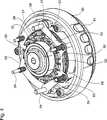
Um die Schwenkbewegung der Achse
Das erste Dämpfungselement
Das zweite Dämpfungselement
Zwischen den jeweiligen Rippen
Die zwei Teile
Die Blattfedern
Die Blattfedern
Um die Druckstifte
Die Handhabe
Wie es am besten aus den
Die Funktionsweise des oben beschriebenen Stativkopfs wird im Folgenden näher erläutert.The operation of the above-described tripod head will be explained in more detail below.
Wird die Achse
In dem in den
Dabei stehen die Eingriffelemente
Um die Dämpfungskraft einstellen zu können, sind die Teile
Wird die Handhabe
Bei der dargestellten Ausführungsform sind somit vier Dämpfungsstufen erzielbar. Eine erste Dampfungsstufe 0, in der die Teile
Die vorstehende Beschreibung einer Ausführungsform ist anhand eines zweiteiligen zweiten Dämpfungselements
Darüber hinaus wurde eine Vorspannung der Eingriffelemente
ZITATE ENTHALTEN IN DER BESCHREIBUNG QUOTES INCLUDE IN THE DESCRIPTION
Diese Liste der vom Anmelder aufgeführten Dokumente wurde automatisiert erzeugt und ist ausschließlich zur besseren Information des Lesers aufgenommen. Die Liste ist nicht Bestandteil der deutschen Patent- bzw. Gebrauchsmusteranmeldung. Das DPMA übernimmt keinerlei Haftung für etwaige Fehler oder Auslassungen.This list of the documents listed by the applicant has been generated automatically and is included solely for the better information of the reader. The list is not part of the German patent or utility model application. The DPMA assumes no liability for any errors or omissions.
Zitierte PatentliteraturCited patent literature
- DE 2657692 A1[0002, 0016]DE 2657692 A1[0002, 0016]
- DE 3833944 A1[0004, 0005]DE 3833944 A1[0004, 0005]
- WO 95/10728 A1[0005]WO 95/10728 A1[0005]
- DE 102007018029 A1[0011, 0044]DE 102007018029 A1[0011, 0044]
- DE 102007018029[0016]DE 102007018029[0016]
Claims (10)
Translated fromGermanPriority Applications (7)
| Application Number | Priority Date | Filing Date | Title |
|---|---|---|---|
| DE202011002608UDE202011002608U1 (en) | 2011-02-11 | 2011-02-11 | tripod head |
| AU2012200722AAU2012200722B2 (en) | 2011-02-11 | 2012-02-07 | Tripod head |
| US13/368,996US9506519B2 (en) | 2011-02-11 | 2012-02-08 | Tripod head |
| EP12154670.9AEP2487382B1 (en) | 2011-02-11 | 2012-02-09 | Tripod head |
| CN201210029702.3ACN102635766B (en) | 2011-02-11 | 2012-02-10 | Heap of tripod |
| JP2012027134AJP5996877B2 (en) | 2011-02-11 | 2012-02-10 | Tripod head |
| US15/244,889US10558109B2 (en) | 2011-02-11 | 2016-08-23 | Tripod head |
Applications Claiming Priority (1)
| Application Number | Priority Date | Filing Date | Title |
|---|---|---|---|
| DE202011002608UDE202011002608U1 (en) | 2011-02-11 | 2011-02-11 | tripod head |
Publications (1)
| Publication Number | Publication Date |
|---|---|
| DE202011002608U1true DE202011002608U1 (en) | 2012-02-29 |
Family
ID=45655511
Family Applications (1)
| Application Number | Title | Priority Date | Filing Date |
|---|---|---|---|
| DE202011002608UExpired - LifetimeDE202011002608U1 (en) | 2011-02-11 | 2011-02-11 | tripod head |
Country Status (6)
| Country | Link |
|---|---|
| US (2) | US9506519B2 (en) |
| EP (1) | EP2487382B1 (en) |
| JP (1) | JP5996877B2 (en) |
| CN (1) | CN102635766B (en) |
| AU (1) | AU2012200722B2 (en) |
| DE (1) | DE202011002608U1 (en) |
Families Citing this family (7)
| Publication number | Priority date | Publication date | Assignee | Title |
|---|---|---|---|---|
| EP2787270B1 (en)* | 2013-04-02 | 2015-12-09 | Vitec Videocom GmbH | A tripod bowl clamp device |
| CN106224717A (en)* | 2016-09-23 | 2016-12-14 | 苏州盛开信息科技有限公司 | A kind of Novel rotary fixing camera fixes seat |
| CN206378673U (en)* | 2017-01-11 | 2017-08-04 | 宁波意美捷影视设备有限公司 | Shooting, the damping mechanism of photography holder |
| US11117002B2 (en)* | 2018-02-09 | 2021-09-14 | Pure Safety Group, Inc. | Brake assembly for use with retractable lifeline assembly |
| DE102018120898A1 (en)* | 2018-08-27 | 2020-02-27 | Thyssenkrupp Ag | Steering column for a motor vehicle |
| TWI767854B (en)* | 2021-10-18 | 2022-06-11 | 角落設計有限公司 | Camera mount |
| CN114576487B (en)* | 2022-03-01 | 2024-01-26 | 江苏未来智慧信息科技有限公司 | Installation device for camera for monitoring power plant |
Citations (5)
| Publication number | Priority date | Publication date | Assignee | Title |
|---|---|---|---|---|
| DE1937011B2 (en)* | 1968-07-22 | 1975-02-20 | Ronford Ltd., Bisley, Surrey (Grossbritannien) | Swivel bearing of a tripod head for a camera or the like |
| DE2657692A1 (en) | 1976-12-20 | 1978-06-22 | Georg Thoma | HYDRAULIC DAMPING MEMBER FOR DAMPING THE ROTATION OF A SHAFT, IN PARTICULAR FOR DAMPING THE PIVOTING MOVEMENT OF A RECORDING DEVICE FOR A FILM OR TELEVISION CAMERA ON A TRIPOD HEAD |
| DE3833944A1 (en) | 1988-06-06 | 1989-12-14 | Guido Cartoni | MODULE ELEMENT AS A COMPONENT OF AN ATTENUATOR FOR CARRYING HEADS OF FILM RECORDING OR TELEVISION CAMERAS FOR PROFESSIONAL KINEMATOGRAPHY AND TELEVISION |
| WO1995010728A1 (en) | 1993-10-14 | 1995-04-20 | Vinten Group Plc | Improvements in or relating to apparatus mountings providing at least one axis of movement with damping |
| DE102007018029B3 (en) | 2007-04-17 | 2008-09-25 | Camera Dynamics Gmbh | tripod head |
Family Cites Families (37)
| Publication number | Priority date | Publication date | Assignee | Title |
|---|---|---|---|---|
| US1238447A (en) | 1912-01-24 | 1917-08-28 | Severy Mfg Company | Clutch. |
| US1829376A (en)* | 1927-09-12 | 1931-10-27 | Steadfast Mfg Co Inc | Spring checking device |
| DE1252785B (en)* | 1963-07-09 | 1967-10-26 | Licentia Gmbh | Spring element for isolating the axial and torsional vibrations of small electric motors in sound equipment |
| DE1279188B (en)* | 1964-05-23 | 1968-10-03 | Bosch Gmbh Robert | AC magnet protected against thermal overload |
| GB1129817A (en) | 1964-12-10 | 1968-10-09 | Nash Alan R B | Improvements in or relating to rotary dampers |
| US3462136A (en)* | 1967-06-29 | 1969-08-19 | Houdaille Industries Inc | Tuned viscous vibration dampers |
| US3464233A (en)* | 1967-12-06 | 1969-09-02 | Caterpillar Tractor Co | Leaf spring coupling |
| DE1805040A1 (en)* | 1968-10-25 | 1970-05-21 | Daimler Benz Ag | Radial seal for a rotary piston internal combustion engine |
| DE2457267C3 (en) | 1974-12-04 | 1980-04-17 | Georg 8021 Sauerlach Thoma | Hydraulic attenuator |
| JPS5614441Y2 (en)* | 1977-05-31 | 1981-04-04 | ||
| CA1090757A (en)* | 1978-05-05 | 1980-12-02 | Gerd Kurz | Camera tripods mounting |
| EP0131881B1 (en)* | 1983-07-13 | 1989-05-03 | Curt Dipl.-Ing. Krönert | Rotational flexible coupling with torque variations damping |
| CH662754A5 (en)* | 1984-03-01 | 1987-10-30 | Escher Wyss Ag | TREATMENT MACHINE WITH ROTATABLE TREATMENT DRUM. |
| FR2577300B1 (en)* | 1985-02-08 | 1987-08-21 | Fremy Raoul | QUICK CONNECTION WITH RADIAL MOVEMENT LOCK |
| DE3525673A1 (en)* | 1985-07-18 | 1987-01-22 | Metzeler Kautschuk | ACTIVE TWO-CHAMBER ENGINE MOUNT WITH HYDRAULIC DAMPING |
| JPS64736U (en)* | 1987-06-22 | 1989-01-05 | ||
| FR2675867A1 (en)* | 1991-04-26 | 1992-10-30 | Guimbretiere Pierre | DEVICE FOR TRANSMISSION WITH A VISCOCOUPLEUR CONTROL, IN PARTICULAR FOR A MOTOR VEHICLE. |
| JPH0544890A (en)* | 1991-08-09 | 1993-02-23 | Heiwa Seiki Kogyo Kk | Universal head |
| GB9207649D0 (en)* | 1992-04-08 | 1992-05-27 | Vinten Group Plc | Improvements in or relating to drag/damper device |
| US5593012A (en)* | 1993-01-19 | 1997-01-14 | Milemarker, Inc. | Limited fixed torque slip coupling |
| US5553834A (en)* | 1993-11-12 | 1996-09-10 | Korea Institute Of Machinery And Metals | Lateral and axial vibration isolators utilizing leaf springs |
| DE9420646U1 (en)* | 1994-12-23 | 1995-02-16 | Itw-Ateco Gmbh, 22844 Norderstedt | Rotary damper |
| GB9519200D0 (en)* | 1995-09-20 | 1995-11-22 | Vinten Group Plc | Improvements in or relating to rotary drag devices |
| US6230450B1 (en)* | 1996-12-27 | 2001-05-15 | Sumitomo Construction Co., Ltd. | Damping top, damping rod, and damping device using same |
| DE10122077A1 (en)* | 2000-10-18 | 2002-05-02 | Tok Bearing Co Ltd | rotary damper |
| FI110202B (en)* | 2001-04-27 | 2002-12-13 | Nokia Corp | Spring Capsule Module |
| KR100391471B1 (en)* | 2001-07-11 | 2003-07-12 | 현대자동차주식회사 | Return spring in a multi-plate clutch for an automatic transmission |
| DE10144682A1 (en)* | 2001-09-11 | 2003-03-27 | Volkswagen Ag | Torsional vibration damper for IC engine camshaft has housing containing damper mass submerged in fluid and connected to housing by leaf springs |
| JP4181831B2 (en)* | 2002-09-09 | 2008-11-19 | 株式会社ニフコ | damper |
| KR101200866B1 (en)* | 2006-07-20 | 2012-11-13 | 삼성전자주식회사 | camera |
| US7600624B2 (en)* | 2006-10-11 | 2009-10-13 | Kabushiki Kaisha F.C.C. | Power transmission apparatus |
| WO2009105861A1 (en)* | 2008-02-28 | 2009-09-03 | Magna Powertrain Inc. | Friction clutch and method to reduce drag loss in friction clutch |
| GB0806663D0 (en)* | 2008-04-11 | 2008-05-14 | Vitec Group Plc The | A pan and tilt head for optical apparatus |
| CN102132058B (en)* | 2008-08-22 | 2014-03-19 | 舍弗勒技术股份两合公司 | Double clutch |
| US8104290B2 (en)* | 2008-10-15 | 2012-01-31 | Alstom Technology Ltd. | Combustion liner damper |
| GB2471261B (en) | 2009-04-09 | 2011-06-08 | Vitec Group Plc | Pan and tilt heads having dual damping |
| EP2299140B1 (en)* | 2009-09-16 | 2013-03-20 | ZF Friedrichshafen AG | Lamella coupling with elastic element |
- 2011
- 2011-02-11DEDE202011002608Upatent/DE202011002608U1/ennot_activeExpired - Lifetime
- 2012
- 2012-02-07AUAU2012200722Apatent/AU2012200722B2/enactiveActive
- 2012-02-08USUS13/368,996patent/US9506519B2/enactiveActive
- 2012-02-09EPEP12154670.9Apatent/EP2487382B1/enactiveActive
- 2012-02-10JPJP2012027134Apatent/JP5996877B2/enactiveActive
- 2012-02-10CNCN201210029702.3Apatent/CN102635766B/enactiveActive
- 2016
- 2016-08-23USUS15/244,889patent/US10558109B2/enactiveActive
Patent Citations (5)
| Publication number | Priority date | Publication date | Assignee | Title |
|---|---|---|---|---|
| DE1937011B2 (en)* | 1968-07-22 | 1975-02-20 | Ronford Ltd., Bisley, Surrey (Grossbritannien) | Swivel bearing of a tripod head for a camera or the like |
| DE2657692A1 (en) | 1976-12-20 | 1978-06-22 | Georg Thoma | HYDRAULIC DAMPING MEMBER FOR DAMPING THE ROTATION OF A SHAFT, IN PARTICULAR FOR DAMPING THE PIVOTING MOVEMENT OF A RECORDING DEVICE FOR A FILM OR TELEVISION CAMERA ON A TRIPOD HEAD |
| DE3833944A1 (en) | 1988-06-06 | 1989-12-14 | Guido Cartoni | MODULE ELEMENT AS A COMPONENT OF AN ATTENUATOR FOR CARRYING HEADS OF FILM RECORDING OR TELEVISION CAMERAS FOR PROFESSIONAL KINEMATOGRAPHY AND TELEVISION |
| WO1995010728A1 (en) | 1993-10-14 | 1995-04-20 | Vinten Group Plc | Improvements in or relating to apparatus mountings providing at least one axis of movement with damping |
| DE102007018029B3 (en) | 2007-04-17 | 2008-09-25 | Camera Dynamics Gmbh | tripod head |
Also Published As
| Publication number | Publication date |
|---|---|
| AU2012200722A1 (en) | 2012-08-30 |
| JP2012168534A (en) | 2012-09-06 |
| AU2012200722B2 (en) | 2014-11-13 |
| US20160357093A1 (en) | 2016-12-08 |
| US20120205516A1 (en) | 2012-08-16 |
| US10558109B2 (en) | 2020-02-11 |
| CN102635766B (en) | 2016-01-20 |
| CN102635766A (en) | 2012-08-15 |
| EP2487382A3 (en) | 2017-10-25 |
| EP2487382A2 (en) | 2012-08-15 |
| JP5996877B2 (en) | 2016-09-21 |
| EP2487382B1 (en) | 2018-12-26 |
| US9506519B2 (en) | 2016-11-29 |
Similar Documents
| Publication | Publication Date | Title |
|---|---|---|
| DE202011002608U1 (en) | tripod head | |
| DE10140270B4 (en) | Crimping pliers for pressing in several notches on the circumference of a contact element | |
| EP3094212B1 (en) | Pivot joint and item of furniture having same | |
| DE102011106696A1 (en) | Screwing element for attaching a cable to a counterpart | |
| EP2919090A2 (en) | Pedal force creation device | |
| DE102016218354A1 (en) | friction clutch | |
| EP2921758A1 (en) | Plug coupling element | |
| DE102012112716A1 (en) | Medical support arm | |
| DE102007018029B3 (en) | tripod head | |
| DE202010007993U1 (en) | Coupling device, in particular for motor vehicle seat adjuster | |
| EP2625442B1 (en) | Clamping roller freewheel for an adjusting device in a motor vehicle | |
| DE202008010143U1 (en) | Electric multi-surface clutch or brake | |
| DE202018106849U1 (en) | Radabzieher | |
| WO2002053965A1 (en) | Balanced camera tripod head | |
| DE202009005811U1 (en) | Crimp Tool | |
| DE102018114289A1 (en) | centrifuge | |
| DE102017128540A1 (en) | coupling device | |
| EP0965699B1 (en) | Device to slidably mount an article, in particular a shower head on a shower bar | |
| AT7580U1 (en) | HOLDING ACTUATOR FOR A MECHANICAL DEVICE AND CONTROLLABLE FRICTION COUPLING WITH SUCH A | |
| WO2013107688A1 (en) | Roller bearing arrangement, in particular release bearing arrangement | |
| DE3850806T2 (en) | Coupling with internal power boost. | |
| DE102012104101B4 (en) | Radial adjustment with locking function | |
| DE102010049137A1 (en) | Spring-loaded drive and high-voltage circuit-breaker | |
| DE102008042001B4 (en) | Spring unit in a hydraulic servo for a friction engagement element | |
| DE202015007091U1 (en) | After the manner of a spreader tine trained hand tool |
Legal Events
| Date | Code | Title | Description |
|---|---|---|---|
| R163 | Identified publications notified | ||
| R207 | Utility model specification | Effective date:20120419 | |
| R150 | Utility model maintained after payment of first maintenance fee after three years | Effective date:20140226 | |
| R151 | Utility model maintained after payment of second maintenance fee after six years | ||
| R152 | Utility model maintained after payment of third maintenance fee after eight years | ||
| R071 | Expiry of right |