DE202010008319U1 - DIN rail and module latching - Google Patents
DIN rail and module latchingDownload PDFInfo
- Publication number
- DE202010008319U1 DE202010008319U1DE202010008319UDE202010008319UDE202010008319U1DE 202010008319 U1DE202010008319 U1DE 202010008319U1DE 202010008319 UDE202010008319 UDE 202010008319UDE 202010008319 UDE202010008319 UDE 202010008319UDE 202010008319 U1DE202010008319 U1DE 202010008319U1
- Authority
- DE
- Germany
- Prior art keywords
- assembly
- module
- mounting rail
- neighboring
- foot part
- Prior art date
- Legal status (The legal status is an assumption and is not a legal conclusion. Google has not performed a legal analysis and makes no representation as to the accuracy of the status listed.)
- Expired - Lifetime
Links
- 238000006073displacement reactionMethods0.000claimsabstractdescription46
- 230000000712assemblyEffects0.000description24
- 238000000429assemblyMethods0.000description24
- 238000009434installationMethods0.000description3
- 210000002414legAnatomy0.000description3
- 238000004519manufacturing processMethods0.000description3
- 210000000689upper legAnatomy0.000description3
- BUHVIAUBTBOHAG-FOYDDCNASA-N(2r,3r,4s,5r)-2-[6-[[2-(3,5-dimethoxyphenyl)-2-(2-methylphenyl)ethyl]amino]purin-9-yl]-5-(hydroxymethyl)oxolane-3,4-diolChemical compoundCOC1=CC(OC)=CC(C(CNC=2C=3N=CN(C=3N=CN=2)[C@H]2[C@@H]([C@H](O)[C@@H](CO)O2)O)C=2C(=CC=CC=2)C)=C1BUHVIAUBTBOHAG-FOYDDCNASA-N0.000description1
- 230000015572biosynthetic processEffects0.000description1
- 239000004020conductorSubstances0.000description1
- 238000010586diagramMethods0.000description1
- 230000002996emotional effectEffects0.000description1
- 230000014759maintenance of locationEffects0.000description1
- 238000000034methodMethods0.000description1
- 230000006855networkingEffects0.000description1
- 238000000926separation methodMethods0.000description1
Images


Classifications
- H—ELECTRICITY
- H02—GENERATION; CONVERSION OR DISTRIBUTION OF ELECTRIC POWER
- H02B—BOARDS, SUBSTATIONS OR SWITCHING ARRANGEMENTS FOR THE SUPPLY OR DISTRIBUTION OF ELECTRIC POWER
- H02B1/00—Frameworks, boards, panels, desks, casings; Details of substations or switching arrangements
- H02B1/015—Boards, panels, desks; Parts thereof or accessories therefor
- H02B1/04—Mounting thereon of switches or of other devices in general, the switch or device having, or being without, casing
- H02B1/052—Mounting on rails
- H—ELECTRICITY
- H01—ELECTRIC ELEMENTS
- H01R—ELECTRICALLY-CONDUCTIVE CONNECTIONS; STRUCTURAL ASSOCIATIONS OF A PLURALITY OF MUTUALLY-INSULATED ELECTRICAL CONNECTING ELEMENTS; COUPLING DEVICES; CURRENT COLLECTORS
- H01R13/00—Details of coupling devices of the kinds covered by groups H01R12/70 or H01R24/00 - H01R33/00
- H01R13/62—Means for facilitating engagement or disengagement of coupling parts or for holding them in engagement
- H01R13/629—Additional means for facilitating engagement or disengagement of coupling parts, e.g. aligning or guiding means, levers, gas pressure electrical locking indicators, manufacturing tolerances
- H01R13/633—Additional means for facilitating engagement or disengagement of coupling parts, e.g. aligning or guiding means, levers, gas pressure electrical locking indicators, manufacturing tolerances for disengagement only
- H—ELECTRICITY
- H01—ELECTRIC ELEMENTS
- H01R—ELECTRICALLY-CONDUCTIVE CONNECTIONS; STRUCTURAL ASSOCIATIONS OF A PLURALITY OF MUTUALLY-INSULATED ELECTRICAL CONNECTING ELEMENTS; COUPLING DEVICES; CURRENT COLLECTORS
- H01R9/00—Structural associations of a plurality of mutually-insulated electrical connecting elements, e.g. terminal strips or terminal blocks; Terminals or binding posts mounted upon a base or in a case; Bases therefor
- H01R9/22—Bases, e.g. strip, block, panel
- H01R9/24—Terminal blocks
- H01R9/26—Clip-on terminal blocks for side-by-side rail- or strip-mounting
- H01R9/2608—Fastening means for mounting on support rail or strip
- H—ELECTRICITY
- H02—GENERATION; CONVERSION OR DISTRIBUTION OF ELECTRIC POWER
- H02B—BOARDS, SUBSTATIONS OR SWITCHING ARRANGEMENTS FOR THE SUPPLY OR DISTRIBUTION OF ELECTRIC POWER
- H02B1/00—Frameworks, boards, panels, desks, casings; Details of substations or switching arrangements
- H02B1/015—Boards, panels, desks; Parts thereof or accessories therefor
- H02B1/04—Mounting thereon of switches or of other devices in general, the switch or device having, or being without, casing
- H02B1/041—Mechanical coupling for side-by-side mounted apparatus
- H—ELECTRICITY
- H02—GENERATION; CONVERSION OR DISTRIBUTION OF ELECTRIC POWER
- H02B—BOARDS, SUBSTATIONS OR SWITCHING ARRANGEMENTS FOR THE SUPPLY OR DISTRIBUTION OF ELECTRIC POWER
- H02B1/00—Frameworks, boards, panels, desks, casings; Details of substations or switching arrangements
- H02B1/015—Boards, panels, desks; Parts thereof or accessories therefor
- H02B1/04—Mounting thereon of switches or of other devices in general, the switch or device having, or being without, casing
- H02B1/052—Mounting on rails
- H02B1/0523—Mounting on rails locked into position by a sliding member
- H—ELECTRICITY
- H02—GENERATION; CONVERSION OR DISTRIBUTION OF ELECTRIC POWER
- H02B—BOARDS, SUBSTATIONS OR SWITCHING ARRANGEMENTS FOR THE SUPPLY OR DISTRIBUTION OF ELECTRIC POWER
- H02B1/00—Frameworks, boards, panels, desks, casings; Details of substations or switching arrangements
- H02B1/26—Casings; Parts thereof or accessories therefor
- H02B1/30—Cabinet-type casings; Parts thereof or accessories therefor
- H02B1/308—Mounting of cabinets together
- Y—GENERAL TAGGING OF NEW TECHNOLOGICAL DEVELOPMENTS; GENERAL TAGGING OF CROSS-SECTIONAL TECHNOLOGIES SPANNING OVER SEVERAL SECTIONS OF THE IPC; TECHNICAL SUBJECTS COVERED BY FORMER USPC CROSS-REFERENCE ART COLLECTIONS [XRACs] AND DIGESTS
- Y10—TECHNICAL SUBJECTS COVERED BY FORMER USPC
- Y10T—TECHNICAL SUBJECTS COVERED BY FORMER US CLASSIFICATION
- Y10T403/00—Joints and connections
- Y10T403/70—Interfitted members
- Y10T403/7075—Interfitted members including discrete retainer
Landscapes
- Engineering & Computer Science (AREA)
- Power Engineering (AREA)
- Mounting Components In General For Electric Apparatus (AREA)
- Connections Arranged To Contact A Plurality Of Conductors (AREA)
Abstract
Translated fromGermanDescription
Translated fromGermanDie Erfindung betrifft eine Baugruppe, insbesondere eine elektrische Baugruppe, die an einer Tragschiene befestigbar und entlang dieser an eine an der Tragschiene angeordnete Nachbarbaugruppe anreihbar ist, sowie ein Fußteil für eine erfindungsgemäße Baugruppe.The invention relates to an assembly, in particular an electrical assembly, which can be fastened to a support rail and along this to a arranged on the support rail adjacent assembly can be arranged, and a foot for a module according to the invention.
Zum Beschalten von elektrischen Baugruppen, beispielsweise von elektrischen Leitern und/oder von Bussystemen und/oder von Modulen komplexer elektronischer Geräte werden häufig Schaltschränke vorgesehen, in denen die elektrischen Baugruppen auf einer Tragschiene aneinander anreihbar sind. Solche elektrischen Baugruppen sind beispielsweise sogenannte Anschlussblöcke, die nicht nur in der Fertigungstechnik, sondern auch zur Vernetzung komplexer Netzwerke Anwendung finden. Die Anschlussblöcke sind durch diese modulare Aneinanderreihbarkeit trotz ihrer Komplexität auch nach der Installation mit verhältnismäßig geringem Aufwand vielfältig veränderbar und einzelne elektrische Baugruppen sind austauschbar.For wiring electrical components, such as electrical conductors and / or bus systems and / or modules of complex electronic devices control cabinets are often provided in which the electrical components are arranged on a support rail to each other. Such electrical assemblies are, for example, so-called terminal blocks, which are not only in manufacturing technology, but also for networking complex networks application. Despite their complexity, even after installation, the connection blocks can be varied in many ways with relatively little effort due to this modular concatenation, and individual electrical components can be exchanged.
In solchen insbesondere normierten Schaltschränken ist es oftmals notwendig, dass die elektrischen Baugruppen unmittelbar aneinander anliegend angereiht werden müssen.In such particular standardized control cabinets, it is often necessary that the electrical components must be joined directly adjacent to each other.
Dabei sollen die elektrischen Baugruppen einerseits möglichst leicht und schnell voneinander lösbar sein. Andererseits dürfen sie sich, insbesondere in einer vibrationsbelasteten Umgebung, wie sie beispielsweise im Bereich der Fertigungstechnik häufig vorzufinden ist, nicht selbsttätig voneinander lösen.In this case, the electrical components on the one hand should be as easily and quickly solvable from each other. On the other hand, they must not automatically separate from one another, in particular in a vibration-stressed environment, as is frequently the case, for example, in the field of production technology.
Die
Weiterhin ist es gegebenenfalls vorteilhaft, in den aneinander anliegenden Wänden zueinander benachbarter elektrischer Baugruppen jeweils elektrische Kontakte vorzusehen, die miteinander Kontaktieren, wenn die elektrischen Baugruppen aneinander anliegend angeordnet sind. Die Aufhebung der Parallelität, und daher ein schräges Lösen der zueinander benachbarten elektrischen Baugruppen voneinander, ist jedoch je nach Ausführungsform der in den zueinander benachbarten Wänden vorgesehenen elektrischen Kontakte, beispielsweise bei als Stecker- und Buchse-System ausgeführten elektrischen Kontakten, nicht ohne weiteres möglich. Denn je nach Bauform der Kontakte besteht die Gefahr, dass die elektrischen Kontakte gegeneinander verkanten, dass Kurzschlüsse entstehen, oder dass die elektrischen Kontakte dabei beschädigt oder sogar zerstört werden.Furthermore, it may be advantageous to provide respective electrical contacts in the adjoining walls of mutually adjacent electrical assemblies which contact each other when the electrical assemblies are arranged adjacent to each other. The repeal of the parallelism, and therefore an oblique release of mutually adjacent electrical assemblies from each other, however, depending on the embodiment of the provided in the mutually adjacent walls electrical contacts, for example when designed as a plug and socket system electrical contacts, not readily possible. Because depending on the design of the contacts, there is a risk that the electrical contacts jam against each other, that short circuits occur, or that the electrical contacts are damaged or even destroyed.
Aufgabe der Erfindung ist es, eine an einer Tragschiene aneinanderreihbare Baugruppe, insbesondere eine elektrischen Baugruppe, zu schaffen, die einfach, schnell, beschädigungsfrei und unter Inanspruchnahme von möglichst wenig Bauraum von einer Nachbarbaugruppe lösbar ist, auch wenn in aneinander anliegenden Seitenwänden aneinandergereihter banachbarter Baugruppen, insbesondere elektrische Kontakte vorgesehen sind, wobei die Baugruppe ein sicheres Aneinanderreihen, insbesondere in vibrationsbelasteter Umgebung, so ermöglicht, dass keine Gefahr eines selbsttätigen voneinander Lösens mehrerer aneinandergereihter Baugruppen besteht, und wobei die Baugruppe kostengünstig herstellbar ist.The object of the invention is to provide an assembly which can be lined up on a mounting rail, in particular an electrical assembly, which can be detached from a neighboring module in a simple, fast, damage-free manner and using as little installation space as possible, even if adjoining side walls are arranged in adjacent rows. In particular, electrical contacts are provided, wherein the assembly allows a secure juxtaposition, especially in vibration-loaded environment, so that there is no danger of an automatic separation of several juxtaposed assemblies, and wherein the assembly is inexpensive to produce.
Die Aufgabe wird gelöst mit einer Baugruppe, insbesondere einer elektrischen Baugruppe, die an einer Tragschiene befestigbar und durch Verschieben in eine Anreihrichtung entlang dieser an eine an der Tragschiene angeordnete Nachbarbaugruppe anreihbar ist, mit einem Grundkörper, und mit einem Fußteil, welches relativ zum Grundkörper in und entgegen eine Verschieberichtung verschiebbar ist, wobei die Baugruppe durch Verschieben des Fußteils in Verschieberichtung von der Nachbarbaugruppe lösbar ist, wobei sie beim Lösen gleichzeitig entgegen die Anreihrichtung von der Nachbarbaugruppe weg verschoben wird.The object is achieved with an assembly, in particular an electrical assembly, which can be fastened to a support rail and arranged by moving in a direction of arrangement along this to a disposed on the support rail adjacent assembly, with a base body, and with a foot part, which relative to the main body in and counter to a displacement direction is displaceable, wherein the assembly is detachable by moving the foot part in the direction of displacement of the adjacent assembly, wherein it is simultaneously displaced against the direction of assembly of the neighboring assembly when loosening.
Beim lösen der Baugruppe von der Nachbarbaugruppe wird diese daher erfindungsgemäß von der Nachbarbaugruppe weg geschoben, so dass die Baugruppe von der Nachbarbaugruppe beabstandet ist. Dadurch ist die Handhabung der Baugruppe für den Bediener sehr einfach. Außerdem wird die Baugruppe definiert von der Nachbarbaugruppe weg geschoben, so dass Bauteile, beispielsweise elektrische Kontakte, die in einander gegenüberliegenden Seitenwänden der Baugruppe und Nachbarbaugruppe angeordnet sind, beim Lösen der Baugruppe nicht beschädigt werden.When the module is detached from the neighboring module, it is therefore pushed away from the neighboring module so that the module is spaced from the neighboring module. This makes handling the assembly very easy for the operator. In addition, the assembly is pushed away from the neighboring assembly in a defined manner so that components such as electrical contacts disposed in opposing side walls of the assembly and neighboring assembly are not damaged upon release of the assembly.
Um die Baugruppe beim Lösen von der Nachbarbaugruppe zu verschieben, ist am Fußteil bevorzugt ein Schiebemittel und am Grundkörper eine Rampe vorgesehen, wobei das Schiebemittel beim Lösen der Baugruppe von der Nachbarbaugruppe an der Rampe entlang gleitet und die Baugruppe gegen die Anreihrichtung verschiebt.In order to move the assembly when releasing the neighboring assembly, a sliding means and a ramp is preferably provided on the base body, wherein the sliding means slides on release of the assembly from the neighboring assembly along the ramp and the assembly moves against the direction of arrangement.
Ebenfalls bevorzugt ist am Fußteil ein Rastmittel vorgesehen, welches mit einem am Grundkörper vorgesehenen Gegenrastmittel so zusammenwirkt, dass das Fußteil beim Lösen der Baugruppe von der Nachbarbaugruppe in einer Offenstellung am Grundkörper verrastet. In der Offenstellung ist die Baugruppe zumindest nicht an der Nachbarbaugruppe verrastet. Bevorzugt ist sie weder an der Nachbarbaugruppe noch an der Tragschiene verrastet, so dass sie der Anordnung entnehmbar ist.Also preferably, a locking means is provided on the foot, which with a on Main body provided counter-locking means cooperates so that the foot when locking the assembly of the neighboring module locked in an open position on the base body. In the open position, the module is at least not locked to the neighboring module. Preferably, it is not latched to the neighboring module nor to the mounting rail, so that it is the arrangement can be removed.
In einer bevorzugten Ausführungsform umfasst die Baugruppe einen Grundkörper sowie ein Fußteil, wobei sie durch Verschieben des Fußteils in eine Verschieberichtung relativ zum Grundkörper sowohl an der Nachbarbaugruppe als auch an der Tragschiene anordbar ist. Für das Anordnen der Baugruppe sowohl an der Tragschiene als auch an der Nachbarbaugruppe ist daher lediglich ein Bauteil, nämlich das Fußteil erforderlich, so dass die Handhabung der Baugruppe beim Anordnen für den Bediener auch dadurch sehr einfach ist.In a preferred embodiment, the assembly comprises a base body and a foot part, wherein it can be arranged by moving the foot part in a direction of displacement relative to the base body both on the neighboring assembly and on the support rail. Therefore, only one component, namely the foot part, is required for arranging the assembly both on the support rail and on the neighboring assembly, so that the handling of the assembly in arranging for the operator is thereby also very simple.
Die Tragschiene erstreckt sich bevorzugt parallel einer Tragschienenebene, wobei sich die Nachbarbaugruppe parallel einer Baugruppenebene erstreckt, wobei die Baugruppe durch Verschieben in eine Aufrastrichtung und/oder Verschwenken in eine Aufrastdrehrichtung, die jeweils parallel der Baugruppenebene verlaufen, an die Tragschiene, und durch Verschieben entlang einer Anreihrichtung, die parallel der Tragschienenebene verläuft, an die Nachbarbaugruppe anordbar ist.The mounting rail preferably extends parallel to a mounting rail plane, wherein the adjacent module extends parallel to an assembly plane, wherein the assembly by moving in a Aufrastrichtung and / or pivoting in a Aufrastdrehrichtung, each parallel to the module level, to the mounting rail, and by moving along a Arrangement direction, which runs parallel to the mounting rail plane, can be arranged to the neighboring module.
Demnach ist die Baugruppe durch Verschieben in eine Aufrastrichtung und/oder Verschwenken in eine Aufrastdrehrichtung, die jeweils parallel einer Baugruppenebene verlaufen, an einer Tragschiene anordbar. Dabei ist die Baugruppenebene die Ebene, in der sich eine an der Tragschiene angeordnete Baugruppe erstreckt. Anschließend ist die Baugruppe an eine Nachbarbaugruppe anordbar, indem sie in eine Anreihrichtung, welche parallel einer Tragschienenebene verläuft, in der sich die Tragschiene erstreckt, verschoben wird. Dadurch ist zum Anordnen einer Baugruppe zwischen zwei benachbarte Nachbarbaugruppen sowie zum Lösen und Entnehmen der Baugruppe lediglich ein Bauraum erforderlich, der nur geringfügig größer als die Tiefe der Baugruppe selbst ist. Im Vergleich zu einem Anschlussblock mit herkömmlichen Baugruppen ist bei einem Anschlussblock mit erfindungsgemäßen Baugruppen daher erheblich mehr Bauraum entlang der Tragschiene nutzbar, und/oder ein solcher Anschlussblock ist entsprechend kleiner baubar.Accordingly, the assembly can be arranged on a support rail by moving in a direction of Aufrastrichtung and / or pivoting in a Aufrastdrehrichtung, each of which runs parallel to a module level. In this case, the module level is the level in which a arranged on the support rail assembly extends. Subsequently, the module can be arranged on a neighboring module by being displaced in a mounting direction which runs parallel to a mounting rail plane in which the mounting rail extends. As a result, only a space that is only slightly larger than the depth of the module itself is required for arranging a module between two adjacent neighboring modules and for releasing and removing the module. Compared to a connection block with conventional modules, therefore, considerably more installation space can be used along the mounting rail in the case of a connection block with assemblies according to the invention, and / or such a connection block can be constructed correspondingly smaller.
Außerdem ermöglicht das Anordnen der Baugruppe an die Nachbarbaugruppe bei etwa paralleler Anordnung zueinander das Vorsehen von Bauteilen in den einander benachbarten, insbesondere aneinander anliegenden, Seitenwänden der Baugruppe und der Nachbarbaugruppe. Dadurch können an einer dieser Seitenwände angeordnete Bauteile, die insbesondere gegenüber der Seitenwand, an der sie angeordnet sind, erhaben sind, beim Anordnen der Baugruppe an die Nachbarbaugruppe in Nachbarbauteile der benachbarten Seitenwand eingesteckt werden, ohne beschädigt zu werden oder Beschädigungen zu verursachen. Die erfindungsgemäße Baugruppe ermöglicht daher das Anordnen von beispielsweise elektrischen Anschlüssen wie Stecker- Buchse Verbindungen in herkömmlicher Bauform an den Seitenwänden der Baugruppe.In addition, arranging the assembly to the neighboring assembly in approximately parallel arrangement allows the provision of components in the adjacent, in particular abutting, side walls of the assembly and the adjacent assembly. As a result, components arranged on one of these side walls, which are raised in particular in relation to the side wall on which they are arranged, can be inserted into adjacent components of the adjacent side wall when the module is arranged on the neighboring module without being damaged or causing damage. The assembly according to the invention therefore enables the arrangement of, for example, electrical connections such as male and female connections in conventional design on the side walls of the module.
In einer bevorzugten Ausführungsform wird die Baugruppe beim Anreihen an die Nachbarbaugruppe an dieser verrastet, so dass sie sich auch in vibrationsbelasteter Umgebung nicht selbsttätig von der Nachbarbaugruppe löst.In a preferred embodiment, the assembly is latched at the adjacent subassembly when it is attached to it, so that it does not detach itself from the neighboring subassembly even in a vibration-stressed environment.
Die Tragschienenebene verläuft vorzugsweise in einem rechten Winkel zur Baugruppenebene. Weiterhin ist es bevorzugt, dass eine die Tragschienenebene schneidende Schnittlinie der Baugruppenebene in einem rechten Winkel zu einer Längserstreckung der Tragschiene verläuft.The mounting rail plane preferably runs at a right angle to the assembly plane. Furthermore, it is preferred that a section line intersecting the mounting rail plane of the module plane extends at a right angle to a longitudinal extension of the mounting rail.
In einer bevorzugten Ausführungsform weist die Baugruppe ein Baugruppenrastmittel auf, welches zum Verrasten der Baugruppe an die Nachbarbaugruppe vorgesehen ist, wobei die Nachbarbaugruppe ein Nachbarbaugruppenrastmittel umfasst, welches beim Verrasten mit dem Baugruppenrastmittel zusammenwirkt, wobei das Baugruppenrastmittel zum Anordnen der Baugruppe an die Nachbarbaugruppe in Verschieberichtung gegen die Kraft eines Kraftmittels verschiebbar, und zum Verrasten der Baugruppe an der Nachbarbaugruppe gegen die Verschieberichtung in Richtung der Kraft zurückschiebbar vorgesehen ist.In a preferred embodiment, the module has a module latching means, which is provided for latching the module to the neighboring module, wherein the neighboring module comprises a neighboring module latching means, which cooperates with the module latching means during latching, wherein the module latching means for arranging the module to the neighboring module in the direction of displacement against the force of a power means displaceable, and is provided for locking the assembly on the adjacent assembly against the direction of displacement in the direction of the force pushed back.
Das Baugruppenrastmittel weicht in dieser Ausführungsform daher beim Anordnen der Baugruppe an die Nachbarbaugruppe dem Nachbaubaugruppenrastmittel aus, so dass die Baugruppe ohne ein Verdrehen oder Verschwenken an die Nachbarbaugruppe anordbar ist, indem sie, bevorzugt in paralleler Anordnung zur Nachbarbaugruppe, in Anreihrichtung verschoben wird. Da das Baugruppenrastmittel aufgrund der Kraft, gegen die es beim Anordnen an die Nachbarbaugruppe verschoben wird, gegen die Verschieberichtung zurück geschoben wird, wird die Baugruppe mit der Kraft des Kraftmittels an der Nachbarbaugruppe gehalten.The module locking means therefore deviates in this embodiment, when arranging the module to the neighboring module from the Nachbaaubaugruppenrastmittel so that the assembly can be arranged without twisting or pivoting to the neighboring module by being moved in the direction of arrangement, preferably in a parallel arrangement to the neighboring module. Since the module locking means is pushed back against the direction of displacement due to the force against which it is displaced when being arranged on the neighboring module, the module is held on the neighboring module with the force of the force means.
Als Kraftmittel ist bevorzugt eine Feder vorgesehen. Es sind aber auch andere beispielsweise elastische Bauteile, die eine Rückstellkraft bewirken, verwendbar.As a force means, a spring is preferably provided. But there are also other example, elastic components that cause a restoring force used.
In einer bevorzugten Ausführungsform weist die Baugruppe weiterhin ein Tragschienenrastmittel auf, welches zum Verrasten der Baugruppe an die Tragschiene vorgesehen ist, wobei die Tragschiene einen Rand aufweist, welcher beim Verrasten mit dem Tragschienenrastmittel zusammenwirkt, so dass das Tragschienenrastmittel zum Anordnen der Baugruppe an die Nachbarbaugruppe in Verschieberichtung gegen die Kraft des Kraftmittels verschieblich, und zum Verrasten der Baugruppe an der Tragschiene gegen die Verschieberichtung in Richtung der Kraft zurückschiebbar vorgesehen ist.In a preferred embodiment, the assembly further comprises a DIN rail locking means on, which is provided for locking the module to the mounting rail, wherein the mounting rail has an edge which cooperates with the locking rail locking means during locking, so that the DIN rail locking means for arranging the module to the adjacent module in the direction of displacement against the force of the power means displaceable, and Locking the module is provided on the support rail against the displacement direction in the direction of the force pushed back.
Auch das Tragschienenrastmittel weicht in dieser Ausführungsform daher beim Anordnen der Baugruppe an die Tragschiene dem Rand der Tragschiene aus. Grundsätzlich ist die Baugruppe daher ebenfalls ohne ein Verdrehen oder Verschwenken an der Tragschiene anordbar, indem sie, bevorzugt in paralleler Anordnung zur Nachbarbaugruppe, in Aufrastrichtung verschoben wird. Und da das Tragschienenrastmittel ebenfalls aufgrund der Kraft, gegen die es beim Anordnen an die Tragschiene verschoben wird, gegen die Verschieberichtung zurück geschoben wird, wird die Baugruppe ebenfalls mit der Kraft des Kraftmittels an der Tragschiene gehalten.The mounting rail locking means also deviates in this embodiment, therefore, when arranging the module to the mounting rail to the edge of the mounting rail. In principle, therefore, the assembly can also be arranged without twisting or pivoting on the mounting rail, by being displaced in the mounting direction, preferably in a parallel arrangement with the neighboring module. And since the DIN rail locking means is also pushed back against the displacement direction due to the force against which it is displaced when arranged on the mounting rail, the assembly is also held with the force of the power means on the mounting rail.
In einer bevorzugten Ausführungsform sind das Baugruppenrastmittel und/oder das Tragschienenrastmittel an dem Fußteil angeordnet. Beim Verschieben des Fußteils werden dann das Baugruppenrastmittel und/oder das Tragschienenrastmittel verschoben.In a preferred embodiment, the module locking means and / or the DIN rail locking means are arranged on the foot part. When moving the foot part then the module locking means and / or the DIN rail locking means are moved.
Dabei ist das Fußteil bevorzugt gegen die Kraft des Kraftmittels in die Verschieberichtung, und in Richtung der Kraft gegen die Verschieberichtung, verschieblich. Weiterhin bevorzugt ist das Fußteil reversibel lösbar am Grundkörper angeordnet. Weiterhin bevorzugt weist es eine Längserstreckung auf, zu der es spiegelsymmetrisch gefertigt ist.In this case, the foot part is preferably displaceable against the force of the force in the direction of displacement, and in the direction of the force against the displacement direction. Further preferably, the foot part is reversibly detachably arranged on the base body. Further preferably, it has a longitudinal extension, to which it is made mirror-symmetrically.
Die Baugruppe ist ebenfalls bevorzugt zu einer Mittellinie spiegelsymmetrisch gefertigt, so dass die Baugruppe auch in zur Tragschiene um 180°gedrehter Anordnung an die Nachbarbaugruppe anreihbar ist.The assembly is also preferably made mirror-symmetrically to a center line, so that the assembly can be arranged in the support rail to 180 ° rotated arrangement to the adjacent module.
Bevorzugt ist die Baugruppe durch Verschieben des Fußteils gegen die Verschieberichtung relativ zum Grundkörper an der Nachbarbaugruppe und der Tragschiene verrastbar. Ebenfalls bevorzugt ist sie durch Verschieben des Fußteils in die Verschieberichtung relativ zum Grundkörper sowohl von der Nachbarbaugruppe als auch von der Tragschiene lösbar.Preferably, the assembly can be latched by moving the foot part against the displacement direction relative to the base body on the adjacent module and the mounting rail. Also preferably, it is releasable by moving the foot in the direction of displacement relative to the base body of both the adjacent assembly and the support rail.
In dieser Ausführungsform sind sowohl das Baugruppenrastmittel als auch das Tragschienenrastmittel am Fußteil angeordnet, so dass durch Verschieben des Fußteils sowohl das Baugruppenrastmittel als auch das Tragschienenrastmittel verschoben wird.In this embodiment, both the module locking means and the DIN rail locking means are arranged on the foot part, so that by displacing the foot part, both the module locking means and the DIN rail locking means is moved.
Besonders bevorzugt ist am Fußteil eine Schräge vorgesehen, die beim Anordnen der Baugruppe an die Tragschiene entlang der Tragschiene gleitet. Dabei wird das Fußteil, und daher gleichzeitig das Tragschienenrastmittel, gegen die Kraft in die Verschieberichtung verschoben.Particularly preferably, a bevel is provided on the foot part, which slides when arranging the assembly to the support rail along the support rail. In this case, the foot part, and therefore at the same time the DIN rail locking means, is moved against the force in the direction of displacement.
In einer weiteren bevorzugten Ausführungsform ist am Fußteil eine Handhabe, insbesondere zur Betätigung mittels eines Schraubendrehers, zum Lösen der Baugruppe von der Nachbarbaugruppe und/oder der Tragschiene vorgesehen, so dass das Lösen der Baugruppe für den Bediener mittels der Handhabe sehr einfach ist.In a further preferred embodiment, a handle, in particular for actuation by means of a screwdriver, for releasing the module from the neighboring module and / or the mounting rail is provided on the foot part, so that the release of the assembly for the operator by means of the handle is very simple.
Um die Handhabung der Baugruppe beim Anordnen und Verrasten an der Tragschiene zu erleichtern, ist zur Befestigung der Baugruppe an der Tragschiene bevorzugt beidseitig der Tragschiene ein Rand vorgesehen, und vorzugsweise sind zwei Tragschienenrastmittel an der Baugruppe anzuordnen, von denen jedes mit einem der Ränder der Tragschiene zusammenwirkt. Die Tragschienenrastmittel sind dabei vorzugsweise so vorgesehen, dass die Baugruppe zunächst parallel der Baugruppe in einer zur Tragschienenebene verschwenkten Stellung mit einem der Tragschienenrastmittel am einen Rand der Tragschiene angeordnet wird, um sie anschließend in Aufrastdrehrichtung zu verschwenken, so dass das andere Tragschienenrastmittel an dem anderen Rand der Tragschiene angeordnet wird. Ebenfalls bevorzugt ist die Baugruppe an der Tragschiene anordbar, indem sie parallel zur Baugruppenebene sowie parallel zur Tragschienenebene angeordnet und in Aufrastrichtung verschoben wird. Die Tragschienenrastmittel weichen dabei den Rändern ebenfalls zunächst aus und werden dann aufgrund der Kraft des Kraftmittels gegen die Verschieberichtung zurück geschoben, wobei die Baugruppe an der Tragschiene verrastet wird.In order to facilitate the handling of the assembly when arranging and latching to the support rail, an edge is preferably provided on both sides of the support rail for attaching the assembly to the support rail, and preferably two mounting rail locking means are to be arranged on the assembly, each of which with one of the edges of the support rail interacts. The DIN rail locking means are preferably provided so that the assembly is initially arranged parallel to the assembly in a position pivoted to the mounting rail level with one of the DIN rail locking means on one edge of the support rail to then pivot in Aufrastdrehrichtung, so that the other DIN rail locking means on the other edge the support rail is arranged. Also preferably, the assembly can be arranged on the support rail by being arranged parallel to the assembly plane and parallel to the mounting rail plane and moved in the direction of the Aufreastrichtung. The DIN rail locking means also soften the edges initially and then be pushed back against the direction of displacement due to the force of the power means, wherein the assembly is latched to the support rail.
Es ist ebenfalls bevorzugt, zwei Baugruppenrastmittel vorzusehen, die mit zwei Nachbarbaugruppenrastmitteln zusammenwirken, um, insbesondere bei großflächigen Baugruppen, die zum Verrasten der Baugruppe an der Nachbarbaugruppe aufzubringende Kraft zu verteilen und/oder eine größere Verrastungssicherheit zu erzielen.It is also preferred to provide two module latching means which cooperate with two adjacent module latching means in order, in particular for large-area assemblies, to distribute the force applied for latching the module to the neighboring module and / or to achieve greater latching security.
Um zwei Tragschienenrastmittel und/oder zwei Baugruppenrastmittel an der Baugruppe vorzusehen, ist es bevorzugt, die Baugruppe mit zwei Fußteilen mit jeweils einem Tragschienenrastmittel und einem Baugruppenrastmittel herzustellen. In dieser Ausführungsform ist die Baugruppe der Anordnung beispielsweise entnehmbar, indem zunächst das eine Fußteil und dann das andere Fußteil in die Offenstellung verschoben werden. Ebenfalls bevorzugt sind die Fußteile so vorgesehen, dass beide Fußteile von der Tragschiene und/oder der Nachbarbaugruppe gleichzeitig lösbar sind.In order to provide two DIN rail locking means and / or two module locking means on the module, it is preferable to manufacture the module with two foot parts, each with a DIN rail locking means and a module locking means. In this embodiment, the assembly of the assembly is removable, for example, by first a foot and then the other foot in the Open position to be postponed. Also preferably, the foot parts are provided so that both foot parts of the support rail and / or the neighboring module are simultaneously detachable.
Die Aufgabe wird weiterhin gelöst mit einem Anschlussblock mit einer Tragschiene und zumindest einer erfindungsgemäßen Baugruppe, die an der Tragschiene anordbar ist.The object is further achieved with a terminal block with a mounting rail and at least one assembly according to the invention, which can be arranged on the support rail.
Nachfolgend wird die Erfindung unter Bezug auf die Zeichnungen anhand von Ausführungsbeispielen näher erläutert, wobei weitere Vorteile der Erfindung deutlich werden. Es zeigt:The invention will be explained in more detail below with reference to the drawings with reference to embodiments, wherein further advantages of the invention will become apparent. It shows:
Die Tragschiene
Die Formulierung, dass sich die Tragschiene
Die an der Tragschiene
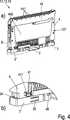
Die
Die Baugruppe
In dem dargestellten Ausführungsbeispiel weist jede der Baugruppen
Die beiden an einer Baugruppe
In der Draufsicht der Seitenwand
Weiterhin sind zwei in dieser Darstellung nicht sichtbare erste Ausnehmungen
Die zur Mittellinie
Beim ersten Aufrasten der Baugruppe
Das Baugruppenrastmittel
Die jeweilige Funktion der weiteren Bauteile wird anhand der folgenden Figuren, vor allem anhand der
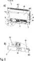
Sichtbar ist in der
Erkennbar ist in dieser Darstellung vor allem, dass an der Nachbarseitenwand
Die Baugruppe
Das Elektronik-Element
In dem Ausschnitt sind vor allem das Nachbarbaugruppenrastmittel
In dem Ausschnitt sind vor allem das Schiebemittel
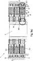
In den
Das Nachbarbaugruppenrastmittel
Das Rastmittel
Dabei wird das Fußteil
Gleichzeitig wird das Baugruppenrastmittel
Das Rastmittel
Beim Loslassen wird das Fußteil
Gleichzeitig wird das Nachbarbaugruppenrastmittel
Die Baugruppe
Der Schraubendreher
Der Vorgang wird anschließend für das andere Fußteil
Da bei diesem hier erläuterten Lösen der Baugruppe
BezugszeichenlisteLIST OF REFERENCE NUMBERS
- 11
- Anschlussblockterminal block
- 1111
- Baugruppemodule
- 112112
- In der verrasteten Stellung an der Nachbarseitenwand der Nachbarbaugruppe anliegende Seitenwand der BaugruppeIn the locked position on the adjacent side wall of the neighboring module adjacent side wall of the module
- 113113
- Seitenwand, an der das Fußteil anordbar istSide wall, on which the foot part can be arranged
- 12 12
- Nachbarbaugruppeneighboring module
- 121121
- In der verrasteten Stellung an der Seitenwand der Baugruppe anliegende Nachbarseitenwand der NachbarbaugruppeIn the latched position on the side wall of the module adjacent adjacent side wall of the neighboring module
- 100, 100'100, 100 '
- Baugruppenebeneassembly level
- 101101
- AufrastrichtungAufrastrichtung
- 102, 102''102, 102 ''
- AufrastdrehrichtungAufrastdrehrichtung
- 103, 103'103, 103 '
- die Tragschienenebene schneidende Schnittlinie der Baugruppenebenethe mounting rail plane intersecting cutting line of the module level
- 104104
- Mittellinie durch die BaugruppeCenter line through the assembly
- 22
- Tragschienerail
- 2222
- Rand, SchenkelEdge, thighs
- 2323
- Querstrebecrossmember
- 2424
- Seitenstrebeside strut
- 200200
- TragschienenebeneRail Level
- 201201
- Anreihrichtungof arrangement
- 202202
- Längserstreckung der TragschieneLongitudinal extension of the mounting rail
- 3, 3''3, 3 ''
- Fußteilfootboard
- 3131
- BaugruppenrastmittelAssemblies latching means
- 3232
- TragschienenrastmittelRail locking means
- 3333
- Schrägeslope
- 3434
- Handhabehandle
- 3535
- Schiebemittelpushing means
- 351351
- Schrägseite des SchiebemittelsOblique side of the pusher
- 3636
- Rastmittellatching means
- 361361
- Hakenförmiges Ende des RastmittelsHook-shaped end of the locking means
- 362362
- Schrägseite des RastmittelsOblique side of the locking means
- 3737
- Stegweb
- 3838
- Längserstreckunglongitudinal extension
- 301, 301''301, 301 ''
- Verschieberichtungdisplacement direction
- 44
- Grundkörperbody
- 4141
- NachbarbaugruppenrastmittelNeighboring modules latching means
- 411411
- Schrägseite des NachbarbaugruppenrastmittelsOblique side of the neighboring assembly catch means
- 412412
- Rastecke des NachbarbaugruppenrastmittelsRetention corner of the neighboring assembly catch
- 4343
- Erste Ausnehmung zur Aufnahme des BaugruppenrastmittelsFirst recess for receiving the module latching means
- 4444
- Anschlussleisteterminal block
- 441441
- Elektrische AnschlüsseElectrical connections
- 442442
- Elektronik-ElementElectronic element
- 4545
- Ramperamp
- 4646
- EntrastmittelEntrastmittel
- 4747
- Gegenstegagainst Steg
- 4848
- Elektrische Kontakte, Stecker, BuchseElectrical contacts, plug, socket
- 4949
- Gegenrastmittel, Zweite Ausnehmung zur Aufnahme des RastmittelsCounter-locking means, second recess for receiving the locking means
- 491491
- Dem Gegenrastmittel zugewandte Fläche des StegteilsThe counter-locking means facing surface of the web portion
- 493493
- Dritte Ausnehmung zur Aufnahme des RastmittelsThird recess for receiving the locking means
- 494494
- Stegteilweb member
- 55
- Betätigungsmittelactuating means
- 5151
- Löserichtungrelease direction
- 66
- Kraftmittel, FederPower means, spring
- 9999
- Winkelangle
- OSOS
- Offenstellungopen position
- VV
- Verrastete Stellung des FußteilsLocked position of the foot part
ZITATE ENTHALTEN IN DER BESCHREIBUNG QUOTES INCLUDE IN THE DESCRIPTION
Diese Liste der vom Anmelder aufgeführten Dokumente wurde automatisiert erzeugt und ist ausschließlich zur besseren Information des Lesers aufgenommen. Die Liste ist nicht Bestandteil der deutschen Patent- bzw. Gebrauchsmusteranmeldung. Das DPMA übernimmt keinerlei Haftung für etwaige Fehler oder Auslassungen.This list of the documents listed by the applicant has been generated automatically and is included solely for the better information of the reader. The list is not part of the German patent or utility model application. The DPMA assumes no liability for any errors or omissions.
Zitierte PatentliteraturCited patent literature
- DE 29916303 U1[0005]DE 29916303 U1[0005]
Claims (15)
Translated fromGermanPriority Applications (5)
| Application Number | Priority Date | Filing Date | Title |
|---|---|---|---|
| DE202010008319UDE202010008319U1 (en) | 2010-08-20 | 2010-08-20 | DIN rail and module latching |
| EP11745746.5AEP2606534B1 (en) | 2010-08-20 | 2011-08-04 | Mounting rail and module latching system |
| CN201180037285.0ACN103038947B (en) | 2010-08-20 | 2011-08-04 | Attachment rail and modular card locking device |
| PCT/EP2011/063420WO2012022621A1 (en) | 2010-08-20 | 2011-08-04 | Mounting rail and module latching system |
| US13/812,724US9263861B2 (en) | 2010-08-20 | 2011-08-04 | Mounting rail and module latching system |
Applications Claiming Priority (1)
| Application Number | Priority Date | Filing Date | Title |
|---|---|---|---|
| DE202010008319UDE202010008319U1 (en) | 2010-08-20 | 2010-08-20 | DIN rail and module latching |
Publications (1)
| Publication Number | Publication Date |
|---|---|
| DE202010008319U1true DE202010008319U1 (en) | 2011-11-21 |
Family
ID=44503822
Family Applications (1)
| Application Number | Title | Priority Date | Filing Date |
|---|---|---|---|
| DE202010008319UExpired - LifetimeDE202010008319U1 (en) | 2010-08-20 | 2010-08-20 | DIN rail and module latching |
Country Status (5)
| Country | Link |
|---|---|
| US (1) | US9263861B2 (en) |
| EP (1) | EP2606534B1 (en) |
| CN (1) | CN103038947B (en) |
| DE (1) | DE202010008319U1 (en) |
| WO (1) | WO2012022621A1 (en) |
Cited By (5)
| Publication number | Priority date | Publication date | Assignee | Title |
|---|---|---|---|---|
| EP2626962A1 (en)* | 2012-02-13 | 2013-08-14 | Siemens Aktiengesellschaft | Clamping assembly for fixing a housing to a rail |
| EP2654137A1 (en)* | 2012-04-18 | 2013-10-23 | Radiall | Multi-terminal connector socket, with quick attachment to a panel and related installation/removal methods |
| US8911263B2 (en) | 2012-04-18 | 2014-12-16 | Radiall | Connection assembly having multi-contact connectors with a polarizing system using keys |
| DE102016203700A1 (en)* | 2016-03-07 | 2017-09-07 | Te Connectivity Germany Gmbh | Rail fastening system with system coupling |
| WO2019025139A1 (en)* | 2017-08-01 | 2019-02-07 | Wago Verwaltungsgesellschaft Mbh | BASE UNIT FOR SERIES MOUNTING INSTALLATION ARRANGEMENT |
Families Citing this family (10)
| Publication number | Priority date | Publication date | Assignee | Title |
|---|---|---|---|---|
| US10201847B2 (en)* | 2014-07-09 | 2019-02-12 | The Boeing Company | Clamping feet for an end effector |
| US9485879B2 (en)* | 2015-03-06 | 2016-11-01 | Rockwell Automation Technologies, Inc. | Single action DIN rail latch |
| DE202016100307U1 (en)* | 2016-01-22 | 2017-04-26 | Weidmüller Interface GmbH & Co. KG | Series device arrangement with a power bus system |
| CN207053967U (en)* | 2017-05-23 | 2018-02-27 | 施耐德电器工业公司 | The locking folder of equipment is kept for low-voltage distribution end product to be fixed to |
| US10734093B1 (en)* | 2019-01-31 | 2020-08-04 | Hewlett Packard Enterprise Development Lp | Chassis mounting for computing devices |
| US10716235B1 (en)* | 2019-02-01 | 2020-07-14 | Cisco Technology, Inc. | Adjustable mounting rail latches |
| US10687433B1 (en) | 2019-06-12 | 2020-06-16 | Phoenix Contact Development and Manufacturing, Inc. | Electrical component enclosure assembly and method of use |
| CN112576869A (en)* | 2019-09-27 | 2021-03-30 | 台达电子工业股份有限公司 | Power supply module |
| DE102022101707A1 (en)* | 2022-01-25 | 2023-07-27 | Weidmüller Interface GmbH & Co. KG | Arrangement with a mounting rail and housings lined up on it |
| US20250286316A1 (en)* | 2022-04-28 | 2025-09-11 | Fanuc Corporation | I/o unit and base unit |
Citations (3)
| Publication number | Priority date | Publication date | Assignee | Title |
|---|---|---|---|---|
| FR2588438A1 (en)* | 1985-10-09 | 1987-04-10 | Telemecanique Electrique | DEVICE FOR ASSEMBLING MODULAR BLOCKS OF ELECTRICAL EQUIPMENT |
| DE4339785A1 (en)* | 1993-11-16 | 1995-05-18 | Wago Verwaltungs Gmbh | Attachment of connector terminals or modules to mounting rail |
| DE29916303U1 (en) | 1999-09-16 | 2001-02-22 | Weidmüller Interface GmbH & Co, 32760 Detmold | Module with coupling elements |
Family Cites Families (14)
| Publication number | Priority date | Publication date | Assignee | Title |
|---|---|---|---|---|
| JPH06859Y2 (en)* | 1988-12-13 | 1994-01-05 | オムロン株式会社 | Mounting device for electrical equipment |
| FR2657200B1 (en)* | 1990-01-12 | 1992-05-15 | Hager Electro | CLIPPING DEVICE FOR MODULAR ELECTRICAL APPARATUS TO BE JOINED AND MODULAR APPARATUS PROVIDED WITH SUCH A DEVICE. |
| US5135415A (en) | 1991-08-12 | 1992-08-04 | Nick Huber | Device for attaching electrical components to track |
| DE4127253A1 (en)* | 1991-08-17 | 1993-02-18 | Abb Patent Gmbh | HOUSING SUITABLE FOR WALL OR FLOOR FASTENING |
| DE29612121U1 (en)* | 1996-07-11 | 1996-09-12 | Heinrich Kopp Ag, 63796 Kahl | Distribution device with space-saving quick attachment for distributors |
| US5904592A (en)* | 1998-09-29 | 1999-05-18 | Allen-Bradley Company, Llc | Dual mode din rail latch with tactile feedback |
| DE10211903A1 (en)* | 2002-03-18 | 2003-10-02 | Eti Elektroelement Dd | Serially fitted electric appliance for installation distributor etc. which can be mounted on support rail, has engagement slider contg. swivel and lock mechanism permitting its arresting in open position |
| DE10243383B3 (en)* | 2002-09-18 | 2004-02-05 | Siemens Ag | Electrical installation device carrier rail fixing uses spring-loaded slider with retention nose secured to housing of installation device |
| AT414287B (en)* | 2002-10-16 | 2006-11-15 | Moeller Gebaeudeautomation Kg | FIXING DEVICE |
| FR2853147B1 (en)* | 2003-03-27 | 2005-05-06 | Schneider Electric Ind Sas | BISTABLE LOCKING DEVICE FOR ELECTRICAL DEVICE SWITCH |
| US7059898B2 (en)* | 2004-10-13 | 2006-06-13 | Rockwell Automation Technologies, Inc. | DIN rail latching system and method |
| US7674129B1 (en)* | 2008-12-22 | 2010-03-09 | Moxa Inc. | Clamping device for DIN rail |
| DE102009037203A1 (en)* | 2009-01-15 | 2010-07-29 | Bartec Gmbh | device |
| US7952859B2 (en)* | 2009-04-03 | 2011-05-31 | Etherwan Systems, Inc. | Fixing device for industrial communication product |
- 2010
- 2010-08-20DEDE202010008319Upatent/DE202010008319U1/ennot_activeExpired - Lifetime
- 2011
- 2011-08-04CNCN201180037285.0Apatent/CN103038947B/enactiveActive
- 2011-08-04USUS13/812,724patent/US9263861B2/ennot_activeExpired - Fee Related
- 2011-08-04WOPCT/EP2011/063420patent/WO2012022621A1/enactiveApplication Filing
- 2011-08-04EPEP11745746.5Apatent/EP2606534B1/enactiveActive
Patent Citations (3)
| Publication number | Priority date | Publication date | Assignee | Title |
|---|---|---|---|---|
| FR2588438A1 (en)* | 1985-10-09 | 1987-04-10 | Telemecanique Electrique | DEVICE FOR ASSEMBLING MODULAR BLOCKS OF ELECTRICAL EQUIPMENT |
| DE4339785A1 (en)* | 1993-11-16 | 1995-05-18 | Wago Verwaltungs Gmbh | Attachment of connector terminals or modules to mounting rail |
| DE29916303U1 (en) | 1999-09-16 | 2001-02-22 | Weidmüller Interface GmbH & Co, 32760 Detmold | Module with coupling elements |
Cited By (9)
| Publication number | Priority date | Publication date | Assignee | Title |
|---|---|---|---|---|
| EP2626962A1 (en)* | 2012-02-13 | 2013-08-14 | Siemens Aktiengesellschaft | Clamping assembly for fixing a housing to a rail |
| WO2013120643A1 (en)* | 2012-02-13 | 2013-08-22 | Siemens Aktiengesellschaft | Clamp fastening for fastening a housing to a rail |
| EP2654137A1 (en)* | 2012-04-18 | 2013-10-23 | Radiall | Multi-terminal connector socket, with quick attachment to a panel and related installation/removal methods |
| FR2989845A1 (en)* | 2012-04-18 | 2013-10-25 | Radiall Sa | MULTI-CONTACTS CONNECTOR BASE, QUICKLY FASTENED TO A PANEL AND ASSOCIATED MOUNTING / DISMANTLING METHODS |
| US8888517B2 (en) | 2012-04-18 | 2014-11-18 | Radiall | Multi-contact connector socket for rapid fastening to a panel |
| US8911263B2 (en) | 2012-04-18 | 2014-12-16 | Radiall | Connection assembly having multi-contact connectors with a polarizing system using keys |
| CN103378489B (en)* | 2012-04-18 | 2017-04-12 | 雷迪埃 | Multi-terminal connector socket, and related installation/removal method therefor |
| DE102016203700A1 (en)* | 2016-03-07 | 2017-09-07 | Te Connectivity Germany Gmbh | Rail fastening system with system coupling |
| WO2019025139A1 (en)* | 2017-08-01 | 2019-02-07 | Wago Verwaltungsgesellschaft Mbh | BASE UNIT FOR SERIES MOUNTING INSTALLATION ARRANGEMENT |
Also Published As
| Publication number | Publication date |
|---|---|
| CN103038947B (en) | 2015-11-25 |
| US9263861B2 (en) | 2016-02-16 |
| WO2012022621A1 (en) | 2012-02-23 |
| CN103038947A (en) | 2013-04-10 |
| EP2606534A1 (en) | 2013-06-26 |
| US20130216304A1 (en) | 2013-08-22 |
| EP2606534B1 (en) | 2019-01-09 |
Similar Documents
| Publication | Publication Date | Title |
|---|---|---|
| EP2606534B1 (en) | Mounting rail and module latching system | |
| EP2339701B1 (en) | Circuit board connector with locking device | |
| DE102017108430B4 (en) | Holding frame for a heavy connector and system | |
| EP2839544B1 (en) | Test terminal block | |
| DE102014106277B4 (en) | An electronics housing with a terminal block for an electronic device | |
| EP3954007B1 (en) | Busbar system with at least one busbar retained in a touch proof housing | |
| DE102007041406A1 (en) | Locking device for a housing for receiving a plug-in module | |
| DE102017124706A1 (en) | Carrier rail housing, electronic module with a mounting rail housing and system, in particular control system, with a plurality of electronic modules | |
| DE202008002111U1 (en) | Bayable electronics housing with pin or socket strips | |
| DE102013019066A1 (en) | Prüfsteckerblock | |
| EP1191643A2 (en) | Housing for an electronic apparatus | |
| DE102006052717A1 (en) | Plug housing module | |
| DE4042060C1 (en) | ||
| DE3826332C1 (en) | Electrical plug connector coupling | |
| EP3440745B1 (en) | Honeycomb component to build a patchboardmodule, patchboard module and tool to remove a honeycomb component from de patchboard module | |
| DE102005016760B4 (en) | Arrangement of electrical or electronic devices | |
| EP2782199A1 (en) | Device for giving commands and/or signals comprising a plug-in coupling | |
| DE102012013404A1 (en) | Plug-in surge arrester | |
| DE102007056252A1 (en) | Electrical plug connector for use in building installation, has detaching unit with finger guided below locking pin during insertion of detaching unit toward pin that is moved perpendicular to finger from locking units by section of pin | |
| DE69607136T2 (en) | Control panel and connection device for electrical installations with modular devices | |
| WO2016162464A1 (en) | Honeycomb component | |
| DE3331035A1 (en) | Electronic control or regulating device | |
| EP0031181A2 (en) | Inserting and withdrawing device for printed circuit assemblies | |
| DE10335496A1 (en) | To be arranged on support elements of an electrical device part | |
| DE1979196U (en) | CONNECTOR FOR FIXING IN MOUNTING WALL CUTOUTS. |
Legal Events
| Date | Code | Title | Description |
|---|---|---|---|
| R163 | Identified publications notified | ||
| R082 | Change of representative | ||
| R207 | Utility model specification | Effective date:20120112 | |
| R150 | Utility model maintained after payment of first maintenance fee after three years | Effective date:20130829 | |
| R151 | Utility model maintained after payment of second maintenance fee after six years | ||
| R152 | Utility model maintained after payment of third maintenance fee after eight years | ||
| R071 | Expiry of right |