DE202010001755U1 - heat pump device - Google Patents
heat pump deviceDownload PDFInfo
- Publication number
- DE202010001755U1 DE202010001755U1DE202010001755UDE202010001755UDE202010001755U1DE 202010001755 U1DE202010001755 U1DE 202010001755U1DE 202010001755 UDE202010001755 UDE 202010001755UDE 202010001755 UDE202010001755 UDE 202010001755UDE 202010001755 U1DE202010001755 U1DE 202010001755U1
- Authority
- DE
- Germany
- Prior art keywords
- pressure sensor
- heat
- heat pump
- compressor
- pump device
- Prior art date
- Legal status (The legal status is an assumption and is not a legal conclusion. Google has not performed a legal analysis and makes no representation as to the accuracy of the status listed.)
- Expired - Lifetime
Links
- 239000003507refrigerantSubstances0.000claimsabstractdescription9
- 238000011144upstream manufacturingMethods0.000abstract1
- XLYOFNOQVPJJNP-UHFFFAOYSA-NwaterSubstancesOXLYOFNOQVPJJNP-UHFFFAOYSA-N0.000description8
- 238000010438heat treatmentMethods0.000description4
- 238000002347injectionMethods0.000description2
- 239000007924injectionSubstances0.000description2
- BUHVIAUBTBOHAG-FOYDDCNASA-N(2r,3r,4s,5r)-2-[6-[[2-(3,5-dimethoxyphenyl)-2-(2-methylphenyl)ethyl]amino]purin-9-yl]-5-(hydroxymethyl)oxolane-3,4-diolChemical compoundCOC1=CC(OC)=CC(C(CNC=2C=3N=CN(C=3N=CN=2)[C@H]2[C@@H]([C@H](O)[C@@H](CO)O2)O)C=2C(=CC=CC=2)C)=C1BUHVIAUBTBOHAG-FOYDDCNASA-N0.000description1
- 230000001419dependent effectEffects0.000description1
- 238000010586diagramMethods0.000description1
- 239000011521glassSubstances0.000description1
- 239000008236heating waterSubstances0.000description1
Images
Classifications
- F—MECHANICAL ENGINEERING; LIGHTING; HEATING; WEAPONS; BLASTING
- F24—HEATING; RANGES; VENTILATING
- F24D—DOMESTIC- OR SPACE-HEATING SYSTEMS, e.g. CENTRAL HEATING SYSTEMS; DOMESTIC HOT-WATER SUPPLY SYSTEMS; ELEMENTS OR COMPONENTS THEREFOR
- F24D19/00—Details
- F24D19/10—Arrangement or mounting of control or safety devices
- F24D19/1006—Arrangement or mounting of control or safety devices for water heating systems
- F24D19/1009—Arrangement or mounting of control or safety devices for water heating systems for central heating
- F24D19/1039—Arrangement or mounting of control or safety devices for water heating systems for central heating the system uses a heat pump
- F—MECHANICAL ENGINEERING; LIGHTING; HEATING; WEAPONS; BLASTING
- F24—HEATING; RANGES; VENTILATING
- F24D—DOMESTIC- OR SPACE-HEATING SYSTEMS, e.g. CENTRAL HEATING SYSTEMS; DOMESTIC HOT-WATER SUPPLY SYSTEMS; ELEMENTS OR COMPONENTS THEREFOR
- F24D19/00—Details
- F24D19/10—Arrangement or mounting of control or safety devices
- F24D19/1006—Arrangement or mounting of control or safety devices for water heating systems
- F24D19/1009—Arrangement or mounting of control or safety devices for water heating systems for central heating
- F24D19/1048—Counting of energy consumption
- F—MECHANICAL ENGINEERING; LIGHTING; HEATING; WEAPONS; BLASTING
- F25—REFRIGERATION OR COOLING; COMBINED HEATING AND REFRIGERATION SYSTEMS; HEAT PUMP SYSTEMS; MANUFACTURE OR STORAGE OF ICE; LIQUEFACTION SOLIDIFICATION OF GASES
- F25B—REFRIGERATION MACHINES, PLANTS OR SYSTEMS; COMBINED HEATING AND REFRIGERATION SYSTEMS; HEAT PUMP SYSTEMS
- F25B30/00—Heat pumps
- F25B30/02—Heat pumps of the compression type
- F—MECHANICAL ENGINEERING; LIGHTING; HEATING; WEAPONS; BLASTING
- F25—REFRIGERATION OR COOLING; COMBINED HEATING AND REFRIGERATION SYSTEMS; HEAT PUMP SYSTEMS; MANUFACTURE OR STORAGE OF ICE; LIQUEFACTION SOLIDIFICATION OF GASES
- F25B—REFRIGERATION MACHINES, PLANTS OR SYSTEMS; COMBINED HEATING AND REFRIGERATION SYSTEMS; HEAT PUMP SYSTEMS
- F25B2500/00—Problems to be solved
- F25B2500/19—Calculation of parameters
- F—MECHANICAL ENGINEERING; LIGHTING; HEATING; WEAPONS; BLASTING
- F25—REFRIGERATION OR COOLING; COMBINED HEATING AND REFRIGERATION SYSTEMS; HEAT PUMP SYSTEMS; MANUFACTURE OR STORAGE OF ICE; LIQUEFACTION SOLIDIFICATION OF GASES
- F25B—REFRIGERATION MACHINES, PLANTS OR SYSTEMS; COMBINED HEATING AND REFRIGERATION SYSTEMS; HEAT PUMP SYSTEMS
- F25B2700/00—Sensing or detecting of parameters; Sensors therefor
- F25B2700/19—Pressures
- F25B2700/193—Pressures of the compressor
- F25B2700/1931—Discharge pressures
- F—MECHANICAL ENGINEERING; LIGHTING; HEATING; WEAPONS; BLASTING
- F25—REFRIGERATION OR COOLING; COMBINED HEATING AND REFRIGERATION SYSTEMS; HEAT PUMP SYSTEMS; MANUFACTURE OR STORAGE OF ICE; LIQUEFACTION SOLIDIFICATION OF GASES
- F25B—REFRIGERATION MACHINES, PLANTS OR SYSTEMS; COMBINED HEATING AND REFRIGERATION SYSTEMS; HEAT PUMP SYSTEMS
- F25B2700/00—Sensing or detecting of parameters; Sensors therefor
- F25B2700/19—Pressures
- F25B2700/193—Pressures of the compressor
- F25B2700/1933—Suction pressures
Landscapes
- Engineering & Computer Science (AREA)
- Physics & Mathematics (AREA)
- Thermal Sciences (AREA)
- Mechanical Engineering (AREA)
- General Engineering & Computer Science (AREA)
- Chemical & Material Sciences (AREA)
- Combustion & Propulsion (AREA)
- Heat-Pump Type And Storage Water Heaters (AREA)
- Measuring Fluid Pressure (AREA)
Abstract
Translated fromGermanDescription
Translated fromGermanDie vorliegende Erfindung betrifft eine Wärmepumpenvorrichtung.The present invention relates to a heat pump device.
Bei Wärmepumpenvorrichtungen ist es wünschenswert, die erzeugte bzw. abgegebene Wärmemenge erfassen und ausgeben zu können.In heat pump devices, it is desirable to be able to detect and output the amount of heat generated or emitted.
Es ist somit eine Aufgabe der vorliegenden Erfindung, eine Wärmepumpenvorrichtung vorzusehen, welche dazu geeignet ist, die erzeugte bzw. abgegebene Wärmemenge zu erfassen und auszugeben, ohne dass weitere Bauteile benötigt werden.It is therefore an object of the present invention to provide a heat pump device which is suitable for detecting and outputting the amount of heat generated or dispensed without the need for further components.
Diese Aufgabe wird durch eine Wärmepumpenvorrichtung gemäß Anspruch 1 gelöst.This object is achieved by a heat pump device according to claim 1.
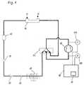
Somit weist die Wärmepumpenvorrichtung einen Kältemittelkreislauf mit einem Verdichter, einem Niederdrucksensor und einem Hochdrucksensor auf. Der Hochdrucksensor und der Niederdrucksensor sind vor und hinter dem Verdichter angeordnet und erfassen den Druck in dem Kältemittelkreislauf vor und hinter dem Verdichter. Die Wärmepumpenvorrichtung weist ferner einen Regler mit einer Wärmemengeneinheit zum Auswerten der durch die Wärmepumpenvorrichtung erzeugten Wärmemenge basierend auf den Signalen des Niederdrucksensors und des Hochdrucksensors auf.Thus, the heat pump device has a refrigerant circuit with a compressor, a low pressure sensor and a high pressure sensor. The high pressure sensor and the low pressure sensor are arranged in front of and behind the compressor and detect the pressure in the refrigerant circuit in front of and behind the compressor. The heat pump apparatus further includes a controller having a heat quantity unit for evaluating the amount of heat generated by the heat pump apparatus based on the signals of the low pressure sensor and the high pressure sensor.
Gemäß einem Aspekt der vorliegenden Erfindung weist die Wärmepumpenvorrichtung eine Anzeigeneinheit zum Anzeigen der durch die Wärmemengeneinheit ausgewerteten Wärmemenge auf.According to one aspect of the present invention, the heat pump device includes a display unit for displaying the amount of heat evaluated by the heat quantity unit.
Gemäß einem weiteren Aspekt der vorliegenden Erfindung weist die Wärmepumpenvorrichtung eine Eingabeeinheit zum Auswählen des Zeitraums für das Auswerten der durch die Wärmepumpenvorrichtung erzeugten Wärmemenge sowie zum Auswählen, welcher Anteil der Wärmemenge anzuzeigen ist, auf.According to another aspect of the present invention, the heat pump apparatus has an input unit for selecting the period of time for evaluating the amount of heat generated by the heat pump apparatus and selecting which proportion of the heat quantity is to be displayed.
Die Erfindung betrifft den Gedanken, eine Wärmepumpenvorrichtung mit einem Kältemittelkreislauf vorzusehen. Der Kältemittelkreislauf weist einen Verdichter sowie einen Niederdrucksensor und einen Hochdrucksensor vor bzw. hinter dem Verdichter auf. Die Wärmepumpeneinheit weist ferner einen Regler auf, welcher mit dem Niederdrucksensor und dem Hochdrucksensor verbunden ist. Der Regler weist eine Wärmemengeneinheit zum Auswerten der durch die Wärmepumpenvorrichtung erzeugten Wärmemenge basierend auf den Signalen von dem Niederdrucksensor und dem Hochdrucksensor auf. Weitere Ausgestaltungen der Erfindung sind Gegenstand der Unteransprüche.The invention relates to the idea to provide a heat pump device with a refrigerant circuit. The refrigerant circuit has a compressor and a low pressure sensor and a high pressure sensor in front of and behind the compressor. The heat pump unit further includes a regulator which is connected to the low pressure sensor and the high pressure sensor. The controller has a heat quantity unit for evaluating the amount of heat generated by the heat pump device based on the signals from the low pressure sensor and the high pressure sensor. Further embodiments of the invention are the subject of the dependent claims.
Vorteile und Ausführungsbeispiele der Erfindung werden nachstehend unter Bezugnahme auf die Zeichnung näher erläutert.Advantages and embodiments of the invention are explained below with reference to the drawing.
Optional kann ein 4-2-Wege Ventil
Optional kann die Wärmepumpenvorrichtung eine Eingabeeinheit und eine Ausgabeeinheit aufweisen. Über die Ausgabeeinheit kann die ermittelte Wärmemenge angezeigt bzw. ausgegeben werden. Mittels der Eingabeeinheit kann der Zeitraum für die Berechnung der Wärmemenge ausgewählt werden. Hierbei kann beispielsweise die Wärmemenge für die Heizung pro Tag angezeigt werden, welche durch den Verdichter erzeugt wird. Alternativ dazu kann die Gesamtwärmemenge der Heizung, die durch den Verdichter erzeugt wird, angezeigt werden. Ferner kann eine Wärmemenge für Warmwasser pro Tag angezeigt werden, welche durch den Verdichter erzeugt wird. Des Weiteren kann eine Gesamtwärmemenge für Warmwasser angezeigt werden, welche durch den Verdichter erzeugt worden ist. Zusätzlich dazu kann die Gesamtwärmemenge der Heizung angezeigt werden, welche durch eine Zusatzheizung, wie beispielsweise einen Durchlauferhitzer, erzeugt wird. Ferner kann die Gesamtwärmemenge des Warmwassers angezeigt werden, welche durch eine Zusatzheizung, wie beispielsweise einen Durchlauferhitzer erzeugt werden. Ferner kann die elektrische Leistungsaufnahme des Verdichters pro Heizung pro Tag angezeigt werden. Des Weiteren kann die Gesamtsumme der elektrischen Leistungsaufnahme des Verdichters für die Heizung angezeigt werden. Ferner kann die elektrische Leistungsaufnahme des Verdichters für Warmwasser pro Tag angezeigt werden. Des Weiteren kann die Gesamtsumme der elektrischen Leistungsaufnahme des Verdichters für Warmwasser angezeigt werden.Optionally, the heat pump device may include an input unit and an output unit. About the output unit, the determined amount of heat can be displayed or output. By means of the input unit, the period for the calculation of the amount of heat can be selected. Here, for example, the amount of heat for the heating per day can be displayed, which is generated by the compressor. Alternatively, the total amount of heat of the heater generated by the compressor may be displayed. Furthermore, an amount of heat for hot water per day can be displayed, which is generated by the compressor. Furthermore, a total amount of heat for hot water that has been generated by the compressor can be displayed. In addition, the total amount of heat of the heater, which is generated by an auxiliary heater, such as a water heater, can be displayed. Furthermore, the total amount of heat of the hot water can be displayed, which are generated by an additional heating, such as a water heater. Furthermore, the electric power consumption of the compressor per heater per day can be displayed. Furthermore, the total sum of the electric power consumption of the compressor for the heating can be displayed. Furthermore, the electric power consumption of the compressor for hot water per day can be displayed. Furthermore, the total sum of the electric power consumption of the compressor for hot water can be displayed.
Die Wärmemengeneinheit
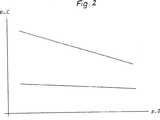
Die elektrische Leistung, welche durch die Wärmepumpenvorrichtung aufgenommen wird, kann anhand der nachfolgenden Gleichung berechnet werden.
In den obigen beiden Gleichungen entspricht der Verflüssigungsdruck p_C, der Verdampferdruck p_0, die Einspritzung aktiv/nicht aktiv E (E = 1; E = 0). Ferner stellen a, b, c, d, e, h Faktoren dar, die beispielsweise an einem Prüfstand ermittelt werden können.In the above two equations, the condensing pressure p_C, the evaporator pressure p_0, the injection active / inactive E (E = 1, E = 0). Furthermore, a, b, c, d, e, h represent factors that can be determined, for example, on a test bench.
Mit dem Niederdrucksensor
ZITATE ENTHALTEN IN DER BESCHREIBUNG QUOTES INCLUDE IN THE DESCRIPTION
Diese Liste der vom Anmelder aufgeführten Dokumente wurde automatisiert erzeugt und ist ausschließlich zur besseren Information des Lesers aufgenommen. Die Liste ist nicht Bestandteil der deutschen Patent- bzw. Gebrauchsmusteranmeldung. Das DPMA übernimmt keinerlei Haftung für etwaige Fehler oder Auslassungen.This list of the documents listed by the applicant has been generated automatically and is included solely for the better information of the reader. The list is not part of the German patent or utility model application. The DPMA assumes no liability for any errors or omissions.
Zitierte PatentliteraturCited patent literature
- DE 2638861 A1[0003]DE 2638861 A1[0003]
Claims (3)
Translated fromGermanPriority Applications (2)
| Application Number | Priority Date | Filing Date | Title |
|---|---|---|---|
| DE202010001755UDE202010001755U1 (en) | 2010-02-02 | 2010-02-02 | heat pump device |
| EP11000563.4AEP2357417B1 (en) | 2010-02-02 | 2011-01-25 | Heat pump device |
Applications Claiming Priority (1)
| Application Number | Priority Date | Filing Date | Title |
|---|---|---|---|
| DE202010001755UDE202010001755U1 (en) | 2010-02-02 | 2010-02-02 | heat pump device |
Publications (1)
| Publication Number | Publication Date |
|---|---|
| DE202010001755U1true DE202010001755U1 (en) | 2011-06-09 |
Family
ID=43795441
Family Applications (1)
| Application Number | Title | Priority Date | Filing Date |
|---|---|---|---|
| DE202010001755UExpired - LifetimeDE202010001755U1 (en) | 2010-02-02 | 2010-02-02 | heat pump device |
Country Status (2)
| Country | Link |
|---|---|
| EP (1) | EP2357417B1 (en) |
| DE (1) | DE202010001755U1 (en) |
Cited By (1)
| Publication number | Priority date | Publication date | Assignee | Title |
|---|---|---|---|---|
| DE102011116622A1 (en)* | 2011-10-20 | 2013-04-25 | Robert Bosch Gmbh | Method for operating a heat pump |
Citations (1)
| Publication number | Priority date | Publication date | Assignee | Title |
|---|---|---|---|---|
| DE2638861A1 (en) | 1976-08-28 | 1978-03-09 | Bosch Gmbh Robert | Heating system with heat pump - has efficiency and heat flow measuring system for continuous recording |
Family Cites Families (3)
| Publication number | Priority date | Publication date | Assignee | Title |
|---|---|---|---|---|
| EP0837291B1 (en)* | 1996-08-22 | 2005-01-12 | Denso Corporation | Vapor compression type refrigerating system |
| US7275377B2 (en)* | 2004-08-11 | 2007-10-02 | Lawrence Kates | Method and apparatus for monitoring refrigerant-cycle systems |
| JP4670329B2 (en)* | 2004-11-29 | 2011-04-13 | 三菱電機株式会社 | Refrigeration air conditioner, operation control method of refrigeration air conditioner, refrigerant amount control method of refrigeration air conditioner |
- 2010
- 2010-02-02DEDE202010001755Upatent/DE202010001755U1/ennot_activeExpired - Lifetime
- 2011
- 2011-01-25EPEP11000563.4Apatent/EP2357417B1/enactiveActive
Patent Citations (1)
| Publication number | Priority date | Publication date | Assignee | Title |
|---|---|---|---|---|
| DE2638861A1 (en) | 1976-08-28 | 1978-03-09 | Bosch Gmbh Robert | Heating system with heat pump - has efficiency and heat flow measuring system for continuous recording |
Cited By (1)
| Publication number | Priority date | Publication date | Assignee | Title |
|---|---|---|---|---|
| DE102011116622A1 (en)* | 2011-10-20 | 2013-04-25 | Robert Bosch Gmbh | Method for operating a heat pump |
Also Published As
| Publication number | Publication date |
|---|---|
| EP2357417A3 (en) | 2016-05-18 |
| EP2357417B1 (en) | 2024-12-04 |
| EP2357417A2 (en) | 2011-08-17 |
Similar Documents
| Publication | Publication Date | Title |
|---|---|---|
| DE112012001851T5 (en) | Determine Fluid Leakage Volumes in Pipelines | |
| DE102012219168B4 (en) | Method for controlling the refrigerant pressure in an ambient heat exchanger of a refrigerant circuit | |
| DE102010049088A1 (en) | Apparatus and method for automatic tire pressure monitoring on a vehicle and method for displaying information for filling a vehicle tire | |
| EP2952865B1 (en) | Method for determining the consumption of gas and electricity of a heating device | |
| DE102008030544B4 (en) | Model-based method for monitoring micromechanical pumps | |
| DE102015001379B4 (en) | Flow Meter | |
| DE102006009047A1 (en) | Pump arrangement for heating system, has flow meter arranged in heating medium path between inlet and outlet connection, and supplies signal corresponding to heating medium flow through heating medium line | |
| DE202010001755U1 (en) | heat pump device | |
| DE102013211708B3 (en) | Test method for a screen in a vehicle | |
| DE102015111876A1 (en) | Method and system for measuring an outside temperature of a vehicle | |
| DE102008035074A1 (en) | Method for measuring the current strength of an alternating current | |
| DE102013114424B4 (en) | Thermal flow sensor and method for determining a volume flow | |
| DE102016008693A1 (en) | Brake system for a motor vehicle | |
| DE102012101859A1 (en) | Pressure sensor for crash sensor system of vehicle, has electrical lead line for supplying power, and test compression device provided in housing of pressure sensor and temporarily connected with lead line of pressure sensor | |
| DE10330414B4 (en) | Method for measuring a pressure | |
| EP1850104A2 (en) | Method for determining the amount of heat of a liquid solar medium in a solar energy system | |
| EP1387148A2 (en) | Method for operating an inductive flow measuring arrangement,as well as flow measuring arrangement | |
| DE102008014160B4 (en) | Instantaneous water heater | |
| DE102014211258A1 (en) | Device for generating defined pressure profiles | |
| DE102017124099A1 (en) | Method for determining a maintenance interval | |
| AT510098A2 (en) | DEVICE FOR SUPPLYING A COMBUSTION ENGINE ON A TEST BENCH CONTAINING AT LEAST ONE USE MEDIUM | |
| DE102013005166A1 (en) | Method for measuring small volume flows in floor heating circuit of central heating based heat supply system, involves operating circuit in normal operation so that valve is operated in position in which volume flow flows through heat sink | |
| DE102017210913A1 (en) | Method for operating a display device | |
| DE102013210762A1 (en) | System for determining a pressure prevailing in a fluid flow | |
| DE102012104022A1 (en) | Method for checking tightness measurement of leakage of fluid used in e.g. automobile industry, involves controlling size of aperture formed in to-be-checked volume based on measured actual value |
Legal Events
| Date | Code | Title | Description |
|---|---|---|---|
| R163 | Identified publications notified | ||
| R207 | Utility model specification | Effective date:20110714 | |
| R163 | Identified publications notified | Effective date:20110713 | |
| R150 | Utility model maintained after payment of first maintenance fee after three years | ||
| R150 | Utility model maintained after payment of first maintenance fee after three years | Effective date:20130312 | |
| R151 | Utility model maintained after payment of second maintenance fee after six years | ||
| R152 | Utility model maintained after payment of third maintenance fee after eight years | ||
| R071 | Expiry of right |