DE202007019497U1 - Breast biopsy and needle localization using tomosynthesis systems - Google Patents
Breast biopsy and needle localization using tomosynthesis systemsDownload PDFInfo
- Publication number
- DE202007019497U1 DE202007019497U1DE202007019497UDE202007019497UDE202007019497U1DE 202007019497 U1DE202007019497 U1DE 202007019497U1DE 202007019497 UDE202007019497 UDE 202007019497UDE 202007019497 UDE202007019497 UDE 202007019497UDE 202007019497 U1DE202007019497 U1DE 202007019497U1
- Authority
- DE
- Germany
- Prior art keywords
- needle
- tomosynthesis
- ray
- breast
- interest
- Prior art date
- Legal status (The legal status is an assumption and is not a legal conclusion. Google has not performed a legal analysis and makes no representation as to the accuracy of the status listed.)
- Expired - Lifetime
Links
- 210000000481breastAnatomy0.000titleclaimsabstractdescription71
- 238000001574biopsyMethods0.000titleclaimsabstractdescription64
- 230000004807localizationEffects0.000titledescription14
- 238000003384imaging methodMethods0.000claimsabstractdescription20
- 210000000038chestAnatomy0.000claimsabstractdescription13
- 239000012780transparent materialSubstances0.000claimsabstractdescription5
- 239000000463materialSubstances0.000claimsdescription26
- 239000002184metalSubstances0.000claimsdescription16
- 229910052751metalInorganic materials0.000claimsdescription16
- 239000007787solidSubstances0.000claimsdescription3
- 230000003902lesionEffects0.000description32
- 210000001519tissueAnatomy0.000description24
- 238000000034methodMethods0.000description17
- 230000006835compressionEffects0.000description16
- 238000007906compressionMethods0.000description16
- 238000009607mammographyMethods0.000description13
- 208000004434CalcinosisDiseases0.000description12
- 230000002308calcificationEffects0.000description12
- 238000013459approachMethods0.000description9
- 210000000779thoracic wallAnatomy0.000description9
- 230000008901benefitEffects0.000description4
- 238000002591computed tomographyMethods0.000description4
- 238000001514detection methodMethods0.000description4
- 238000003780insertionMethods0.000description4
- 230000037431insertionEffects0.000description4
- 231100000915pathological changeToxicity0.000description4
- 230000036285pathological changeEffects0.000description4
- 239000000047productSubstances0.000description4
- 239000002872contrast mediaSubstances0.000description3
- 238000011161developmentMethods0.000description3
- 230000018109developmental processEffects0.000description3
- 239000004033plasticSubstances0.000description3
- 229920003023plasticPolymers0.000description3
- 238000012216screeningMethods0.000description3
- 241000272517AnseriformesSpecies0.000description2
- 239000000919ceramicSubstances0.000description2
- 238000013461designMethods0.000description2
- 238000005516engineering processMethods0.000description2
- 239000003193general anesthetic agentSubstances0.000description2
- 238000013188needle biopsyMethods0.000description2
- 230000007170pathologyEffects0.000description2
- 230000035515penetrationEffects0.000description2
- 238000005070samplingMethods0.000description2
- 238000010561standard procedureMethods0.000description2
- 238000002604ultrasonographyMethods0.000description2
- 230000004304visual acuityEffects0.000description2
- 238000012800visualizationMethods0.000description2
- BUHVIAUBTBOHAG-FOYDDCNASA-N(2r,3r,4s,5r)-2-[6-[[2-(3,5-dimethoxyphenyl)-2-(2-methylphenyl)ethyl]amino]purin-9-yl]-5-(hydroxymethyl)oxolane-3,4-diolChemical compoundCOC1=CC(OC)=CC(C(CNC=2C=3N=CN(C=3N=CN=2)[C@H]2[C@@H]([C@H](O)[C@@H](CO)O2)O)C=2C(=CC=CC=2)C)=C1BUHVIAUBTBOHAG-FOYDDCNASA-N0.000description1
- 241001136792AlleSpecies0.000description1
- OKTJSMMVPCPJKN-UHFFFAOYSA-NCarbonChemical compound[C]OKTJSMMVPCPJKN-UHFFFAOYSA-N0.000description1
- 206010028980NeoplasmDiseases0.000description1
- 230000001154acute effectEffects0.000description1
- 230000003444anaesthetic effectEffects0.000description1
- 229940035674anestheticsDrugs0.000description1
- 210000000988bone and boneAnatomy0.000description1
- 238000004364calculation methodMethods0.000description1
- 201000011510cancerDiseases0.000description1
- 229910052799carbonInorganic materials0.000description1
- 239000003795chemical substances by applicationSubstances0.000description1
- 238000013170computed tomography imagingMethods0.000description1
- 230000003247decreasing effectEffects0.000description1
- 238000010586diagramMethods0.000description1
- 230000008030eliminationEffects0.000description1
- 238000003379elimination reactionMethods0.000description1
- 239000011521glassSubstances0.000description1
- 238000001727in vivoMethods0.000description1
- 238000007373indentationMethods0.000description1
- 230000007246mechanismEffects0.000description1
- 150000002739metalsChemical class0.000description1
- 210000002445nippleAnatomy0.000description1
- 238000002355open surgical procedureMethods0.000description1
- 230000037368penetrate the skinEffects0.000description1
- 238000012805post-processingMethods0.000description1
- 238000012545processingMethods0.000description1
- 230000001629suppressionEffects0.000description1
- 238000001356surgical procedureMethods0.000description1
- 230000001360synchronised effectEffects0.000description1
Images


Classifications
- A—HUMAN NECESSITIES
- A61—MEDICAL OR VETERINARY SCIENCE; HYGIENE
- A61B—DIAGNOSIS; SURGERY; IDENTIFICATION
- A61B6/00—Apparatus or devices for radiation diagnosis; Apparatus or devices for radiation diagnosis combined with radiation therapy equipment
- A61B6/02—Arrangements for diagnosis sequentially in different planes; Stereoscopic radiation diagnosis
- A61B6/025—Tomosynthesis
- A—HUMAN NECESSITIES
- A61—MEDICAL OR VETERINARY SCIENCE; HYGIENE
- A61B—DIAGNOSIS; SURGERY; IDENTIFICATION
- A61B10/00—Instruments for taking body samples for diagnostic purposes; Other methods or instruments for diagnosis, e.g. for vaccination diagnosis, sex determination or ovulation-period determination; Throat striking implements
- A61B10/0041—Detection of breast cancer
- A—HUMAN NECESSITIES
- A61—MEDICAL OR VETERINARY SCIENCE; HYGIENE
- A61B—DIAGNOSIS; SURGERY; IDENTIFICATION
- A61B10/00—Instruments for taking body samples for diagnostic purposes; Other methods or instruments for diagnosis, e.g. for vaccination diagnosis, sex determination or ovulation-period determination; Throat striking implements
- A61B10/02—Instruments for taking cell samples or for biopsy
- A61B10/0233—Pointed or sharp biopsy instruments
- A61B10/0266—Pointed or sharp biopsy instruments means for severing sample
- A61B10/0275—Pointed or sharp biopsy instruments means for severing sample with sample notch, e.g. on the side of inner stylet
- A—HUMAN NECESSITIES
- A61—MEDICAL OR VETERINARY SCIENCE; HYGIENE
- A61B—DIAGNOSIS; SURGERY; IDENTIFICATION
- A61B6/00—Apparatus or devices for radiation diagnosis; Apparatus or devices for radiation diagnosis combined with radiation therapy equipment
- A61B6/04—Positioning of patients; Tiltable beds or the like
- A61B6/0407—Supports, e.g. tables or beds, for the body or parts of the body
- A61B6/0435—Supports, e.g. tables or beds, for the body or parts of the body with means for imaging suspended breasts
- A—HUMAN NECESSITIES
- A61—MEDICAL OR VETERINARY SCIENCE; HYGIENE
- A61B—DIAGNOSIS; SURGERY; IDENTIFICATION
- A61B6/00—Apparatus or devices for radiation diagnosis; Apparatus or devices for radiation diagnosis combined with radiation therapy equipment
- A61B6/46—Arrangements for interfacing with the operator or the patient
- A61B6/461—Displaying means of special interest
- A61B6/463—Displaying means of special interest characterised by displaying multiple images or images and diagnostic data on one display
- A—HUMAN NECESSITIES
- A61—MEDICAL OR VETERINARY SCIENCE; HYGIENE
- A61B—DIAGNOSIS; SURGERY; IDENTIFICATION
- A61B6/00—Apparatus or devices for radiation diagnosis; Apparatus or devices for radiation diagnosis combined with radiation therapy equipment
- A61B6/46—Arrangements for interfacing with the operator or the patient
- A61B6/461—Displaying means of special interest
- A61B6/466—Displaying means of special interest adapted to display 3D data
- A—HUMAN NECESSITIES
- A61—MEDICAL OR VETERINARY SCIENCE; HYGIENE
- A61B—DIAGNOSIS; SURGERY; IDENTIFICATION
- A61B6/00—Apparatus or devices for radiation diagnosis; Apparatus or devices for radiation diagnosis combined with radiation therapy equipment
- A61B6/46—Arrangements for interfacing with the operator or the patient
- A61B6/467—Arrangements for interfacing with the operator or the patient characterised by special input means
- A61B6/469—Arrangements for interfacing with the operator or the patient characterised by special input means for selecting a region of interest [ROI]
- A—HUMAN NECESSITIES
- A61—MEDICAL OR VETERINARY SCIENCE; HYGIENE
- A61B—DIAGNOSIS; SURGERY; IDENTIFICATION
- A61B6/00—Apparatus or devices for radiation diagnosis; Apparatus or devices for radiation diagnosis combined with radiation therapy equipment
- A61B6/50—Apparatus or devices for radiation diagnosis; Apparatus or devices for radiation diagnosis combined with radiation therapy equipment specially adapted for specific body parts; specially adapted for specific clinical applications
- A61B6/502—Apparatus or devices for radiation diagnosis; Apparatus or devices for radiation diagnosis combined with radiation therapy equipment specially adapted for specific body parts; specially adapted for specific clinical applications for diagnosis of breast, i.e. mammography
- A—HUMAN NECESSITIES
- A61—MEDICAL OR VETERINARY SCIENCE; HYGIENE
- A61B—DIAGNOSIS; SURGERY; IDENTIFICATION
- A61B6/00—Apparatus or devices for radiation diagnosis; Apparatus or devices for radiation diagnosis combined with radiation therapy equipment
- A61B6/54—Control of apparatus or devices for radiation diagnosis
- A61B6/542—Control of apparatus or devices for radiation diagnosis involving control of exposure
- A—HUMAN NECESSITIES
- A61—MEDICAL OR VETERINARY SCIENCE; HYGIENE
- A61B—DIAGNOSIS; SURGERY; IDENTIFICATION
- A61B90/00—Instruments, implements or accessories specially adapted for surgery or diagnosis and not covered by any of the groups A61B1/00 - A61B50/00, e.g. for luxation treatment or for protecting wound edges
- A61B90/10—Instruments, implements or accessories specially adapted for surgery or diagnosis and not covered by any of the groups A61B1/00 - A61B50/00, e.g. for luxation treatment or for protecting wound edges for stereotaxic surgery, e.g. frame-based stereotaxis
- A61B90/11—Instruments, implements or accessories specially adapted for surgery or diagnosis and not covered by any of the groups A61B1/00 - A61B50/00, e.g. for luxation treatment or for protecting wound edges for stereotaxic surgery, e.g. frame-based stereotaxis with guides for needles or instruments, e.g. arcuate slides or ball joints
- A—HUMAN NECESSITIES
- A61—MEDICAL OR VETERINARY SCIENCE; HYGIENE
- A61B—DIAGNOSIS; SURGERY; IDENTIFICATION
- A61B90/00—Instruments, implements or accessories specially adapted for surgery or diagnosis and not covered by any of the groups A61B1/00 - A61B50/00, e.g. for luxation treatment or for protecting wound edges
- A61B90/10—Instruments, implements or accessories specially adapted for surgery or diagnosis and not covered by any of the groups A61B1/00 - A61B50/00, e.g. for luxation treatment or for protecting wound edges for stereotaxic surgery, e.g. frame-based stereotaxis
- A61B90/14—Fixators for body parts, e.g. skull clamps; Constructional details of fixators, e.g. pins
- A61B90/17—Fixators for body parts, e.g. skull clamps; Constructional details of fixators, e.g. pins for soft tissue, e.g. breast-holding devices
- A—HUMAN NECESSITIES
- A61—MEDICAL OR VETERINARY SCIENCE; HYGIENE
- A61B—DIAGNOSIS; SURGERY; IDENTIFICATION
- A61B90/00—Instruments, implements or accessories specially adapted for surgery or diagnosis and not covered by any of the groups A61B1/00 - A61B50/00, e.g. for luxation treatment or for protecting wound edges
- A61B90/36—Image-producing devices or illumination devices not otherwise provided for
- A61B90/37—Surgical systems with images on a monitor during operation
- A61B2090/376—Surgical systems with images on a monitor during operation using X-rays, e.g. fluoroscopy
- A—HUMAN NECESSITIES
- A61—MEDICAL OR VETERINARY SCIENCE; HYGIENE
- A61B—DIAGNOSIS; SURGERY; IDENTIFICATION
- A61B6/00—Apparatus or devices for radiation diagnosis; Apparatus or devices for radiation diagnosis combined with radiation therapy equipment
- A61B6/04—Positioning of patients; Tiltable beds or the like
- A61B6/0407—Supports, e.g. tables or beds, for the body or parts of the body
- A61B6/0414—Supports, e.g. tables or beds, for the body or parts of the body with compression means
- A—HUMAN NECESSITIES
- A61—MEDICAL OR VETERINARY SCIENCE; HYGIENE
- A61B—DIAGNOSIS; SURGERY; IDENTIFICATION
- A61B6/00—Apparatus or devices for radiation diagnosis; Apparatus or devices for radiation diagnosis combined with radiation therapy equipment
- A61B6/12—Arrangements for detecting or locating foreign bodies
- A—HUMAN NECESSITIES
- A61—MEDICAL OR VETERINARY SCIENCE; HYGIENE
- A61B—DIAGNOSIS; SURGERY; IDENTIFICATION
- A61B6/00—Apparatus or devices for radiation diagnosis; Apparatus or devices for radiation diagnosis combined with radiation therapy equipment
- A61B6/48—Diagnostic techniques
- A61B6/481—Diagnostic techniques involving the use of contrast agents
Landscapes
- Health & Medical Sciences (AREA)
- Life Sciences & Earth Sciences (AREA)
- Engineering & Computer Science (AREA)
- Medical Informatics (AREA)
- Surgery (AREA)
- Veterinary Medicine (AREA)
- Heart & Thoracic Surgery (AREA)
- Molecular Biology (AREA)
- Biomedical Technology (AREA)
- Animal Behavior & Ethology (AREA)
- General Health & Medical Sciences (AREA)
- Public Health (AREA)
- Pathology (AREA)
- Nuclear Medicine, Radiotherapy & Molecular Imaging (AREA)
- Physics & Mathematics (AREA)
- Biophysics (AREA)
- High Energy & Nuclear Physics (AREA)
- Optics & Photonics (AREA)
- Radiology & Medical Imaging (AREA)
- Human Computer Interaction (AREA)
- Oral & Maxillofacial Surgery (AREA)
- Dentistry (AREA)
- Neurosurgery (AREA)
- Oncology (AREA)
- Apparatus For Radiation Diagnosis (AREA)
Abstract
Translated fromGermanDescription
Translated fromGermanSTAND DER TECHNIK UND ZUSAMMENFASSUNG DER ERFINDUNGSTATE OF THE ART AND SUMMARY OF THE INVENTION
Die Mammografie ist ein wohlbekanntes etabliertes Verfahren der bildgebenden Brustuntersuchung. Durch die Verwendung von Mammogrammen der Brust identifizieren Radiologen verdächtige Bereiche mit pathologischen Veränderungen. Eine weitergehende Identifizierung, wie beispielsweise die Feststellung von Krebs, wird normalerweise durch die Entnahme einer Brustbiopsie durchgeführt. Dies erfolgt auf verschiedenen Wegen. Ein Weg ist die Markierung der verdächtigen pathologischen Stelle durch das Platzieren von einem Draht oder einer Nadel in der Brust. Die Patientin wird anschließend einem offenen chirurgischen Verfahren unterzogen und der Chirurg kann dabei Gewebe aus dem verdächtigen Bereich, der durch den Draht oder die Nadel markiert wurde, entfernen. Die ist eine offene chirurgische Biopsie. Ein weiteres Verfahren ist als stereotaktische Brustbiopsie bekannt. Bei diesem Verfahren wird unter Verwendung von der Bildnavigation eine Hohlnadel in die Brust eingeführt und eine Gewebeprobe aus dem interessierenden Bereich ohne eine separates chirurgisches Verfahren entnommen. Wie vorangehend angemerkt, benötigen beide Verfahren eine Methode zur Lokalisation des interessierenden Bereichs und ein Verfahren zur Steuerung von einem Draht oder einer Nadel in die Brust, sodass sie in dem bereits identifizierten interessierenden Bereich liegt.Mammography is a well known established method of breast imaging. By using breast mammograms, radiologists identify suspicious areas with pathological changes. Further identification, such as detection of cancer, is usually performed by taking a breast biopsy. This is done in different ways. One way is to mark the suspect pathology site by placing a wire or needle in the chest. The patient is then subjected to an open surgical procedure and the surgeon can remove tissue from the suspicious area marked by the wire or the needle. That's an open surgical biopsy. Another method is known as stereotactic breast biopsy. In this method, a hollow needle is inserted into the breast using image navigation, and a tissue sample is removed from the area of interest without a separate surgical procedure. As noted above, both methods require a method of localizing the region of interest and a method of directing a wire or needle into the breast to lie within the region of interest already identified.
Diese Offenbarung beschriebt Systeme zur Orientierung der Draht- und/oder Nadelführung in die Brust unter Verwendung der bildgebenden Tomosynthese-Technologie. Diese umfassen Biopsie-Ausrüstungen sowohl für die aufrechte als auch die liegende Position.This disclosure describes systems for orienting the wire and / or needle guide into the breast using tomosynthesis imaging technology. These include biopsy equipment for both the upright and recumbent positions.
Die Tomosynthese (Tomo) ist ein Verfahren zur Durchführung dreidimensionaler (3D-) Röntgenaufnahmen der Brust. Es erzeugt Aufnahmen von Querschnittsschichten durch eine komprimierte Brust und sie wird ebenfalls zur Identifizierung von pathologischen Veränderungen in der Brust verwendet. Einer der Vorteile der Tomosynthese ist, dass die Aufnahmen dreidimensional sind, sodass sobald ein interessierender Bereich in einer Aufnahme identifiziert wurde, seine präzisen 3D-Koordinaten in der Brust berechnet oder festgestellt werden können, z. B. aus den X, Y-Koordinaten in der Aufnahme einer Schicht und aus der Z-Koordinate, oder der Tiefe, welche durch die Tiefenlage der Schichtaufnahme gegeben ist. Ein weiterer Vorteil der Tomosynthese ist ihre Fähigkeit, ein hohes kontrastreiches Auflösungsvermögen von Objekten durch die Unterdrückung der Abbildung von Objekten in unterschiedlichen Höhen in den Brüsten bereitzustellen. Aufgrund des überlegenen kontrastreichen Auflösungsvermögens ist zu erwarten, dass pathologische Veränderungen auf den Tomosyntheseaufnahmen zu sehen sein werden, wie sie unter Verwendung der Standard-Röntgenmammographie oder von stereotaktischen Vorrichtungen oder unter Verwendung von Ultraschall oder sogar MRI oder anderen Verfahren, die gegenwärtig eingesetzt werden, um eine Orientierungshilfe für das Einsetzen von Drähten und Nadeln an die Stelle eines identifizierten interessierenden Bereichs bereitzustellen, nicht zu sehen sind. Aus diesem Grund ist es erwünscht, Lokalisationsverfahren unter Anwendung von Tomosynthesesystemen zu entwickeln, welche die Fähigkeiten der Tomosynthese zur natürlichen 3D-Lokalisation nutzen.Tomosynthesis (Tomo) is a procedure for performing three-dimensional (3D) X-ray images of the breast. It produces images of cross-sectional layers through a compressed breast and is also used to identify pathological changes in the breast. One of the advantages of tomosynthesis is that the images are three-dimensional so that once a region of interest has been identified in a photograph, its precise 3D coordinates in the breast can be calculated or determined, e.g. B. from the X, Y coordinates in the recording of a layer and from the Z coordinate, or the depth, which is given by the depth of the film recording. Another advantage of tomosynthesis is its ability to provide high contrast resolving power of objects by suppressing the imaging of objects at different levels in the breasts. Because of the superior high contrast resolving power, it is expected that pathological changes will be seen on tomosynthesis images, such as those obtained using standard X-ray mammography or stereotactic devices, or using ultrasound or even MRI or other methods currently used to provide an orientation guide for the insertion of wires and needles in place of an identified region of interest, can not be seen. For this reason, it is desired to develop localization methods using tomosynthesis systems which utilize the capabilities of tomosynthesis for natural 3D localization.
Die vorliegende Offenbarung befasst sich sowohl mit den Systemen für die Tomosynthese-Bildgebung als auch den Vorrichtungen für die Nadel- und Drahtlokalisierung unter Verwendung von Tomosynthese-Bildgebungssystemen. In einem nicht-einschränkenden Beispiel basiert die neue Herangehensweise, die in dieser Offenlegungsschrift beschrieben wird, auf herkömmlichen Tomosynthese-Entwicklungen, z. B. wie sie beschrieben sind in der US-Patentanmeldung Serien-Nr. 10/305,480, eingereicht am 27. November 2002, US-Patentanmeldung Serien-Nr. 10/723,486, eingereicht am 26. November 2003, vorläufige US-Patentanmeldung Serien-Nr. 60/628,516, eingereicht am 15. November 2004, Internationale PCT-Anmeldung Serien-Nr. PCT/US2005/0491941, eingereicht am 15. November 2005, vorläufige US-Patentanmeldung Serien-Nr. 60/631,296, eingereicht am 26. November 2004, und Internationale PCT-Anmeldung Serien-Nr. PCT/US2005/042613, eingereicht am 23. November 2005, die hiermit durch Verweis aufgenommen sind. Typischerweise wird die Brust zwischen einer Brustplatte und einer Kompressionsplatte komprimiert. Die Kompressionsplatte kann eine der Standardplatten sein, wie sie für das Screening bei der Mammografie verwendet werden oder eine mit Löchern und Führungsmarken, wie sie für die Nadellokalisation oder für Biopsieverfahren mit herkömmlicher Mammografie-Ausstattung verwendet werden, zum Beispiel wie sie beschrieben ist in der
Die Lokalisation eines interessierenden Bereichs kann mit der Erfassung der Brust starten, die in einem in der Brust-Tomosynthese verwendeten Standardverfahren durchgeführt wird. Die Daten werden rekonstruiert und begutachtet. Der interessierende Bereich wird entweder auf den rekonstruierten Aufnahmen der Schichten oder den unbearbeiteten Projektionsbildern identifiziert. Die 3D-Koordinaten des interessierenden Bereichs können berechnet oder von der Identifizierung des interessierenden Bereichs auf den Aufnahmen abgeschätzt werden.The location of a region of interest may start with the detection of the breast performed in a standard procedure used in breast tomosynthesis. The data is reconstructed and examined. The area of interest is identified either on the reconstructed shots of the layers or the unprocessed projection images. The 3D coordinates of the region of interest may be calculated or estimated from the identification of the region of interest on the images.
Sobald die 3D-Lokalisierung des interessierenden Bereichs berechnet wurde können die für die Lenkung von Nadeln und Drähten zu dieser Stelle bekannten Verfahren angewendet werden.Once the 3D localization of the area of interest has been calculated, the methods known for steering needles and wires to that location can be used.
Es können einige Unterschiede in den Tomosyntheseabtastungen während der Biopsieverfahren gegenüber dem Mammographie-Screening vorliegen. Die Dosis kann höher sein, um rauschärmere Aufnahmen zu erhalten. Der Winkelbereich kann breiter oder flacher sein und die Anzahl der Projektionen kann größer oder kleiner sein. Es könnte zum Beispiel ein breiterer Winkel wünschenswert sein, um eine höhere Präzision der Tiefendiskriminierung zu erhalten. Es könnte ebenfalls eine höhere Auflösung im Vergleich zu dem herkömmlichen Tomosynthese-Screening für diese Abtastungen wünschenswert sein. Dies würde durch die Verwendung kleinerer Pixelgrößen bewerkstelligt werden.There may be some differences in tomosynthesis scans during biopsy procedures over mammography screening. The dose may be higher for lower noise recordings. The angle range may be wider or flatter, and the number of projections may be larger or smaller. For example, a wider angle might be desirable to obtain higher precision of depth discrimination. Also, a higher resolution could be desirable compared to conventional tomosynthesis screening for these scans. This would be accomplished by using smaller pixel sizes.
Ein mit einem Tomosynthesesystem verwendetes Biopsiesystem kann eine Nadel-Abschussvorrichtung mit motorisiertem oder unmotorisierten Tisch einschließen, welche eine Nadel auf eine spezifische 3D-Koordinate in der Brust lenken kann. Dieser Tisch kann aus dem Weg des Erfassungssystems während der ersten Tomosyntheseabtastung geschwungen oder auf eine andere Art und Weise herausbewegt werden, sodass, wenn es erwünscht ist, dass der Tisch nicht die Visualisierung der Brust oder den interessierenden Bereich der Brust beschattet oder beeinträchtigt.A biopsy system used with a tomosynthesis system may include a motorized or unmotorized table-type needle launcher which can direct a needle to a specific 3D coordinate in the breast. This table may be swung out of the way of the detection system during the first tomosynthesis scan, or otherwise moved out so that, if desired, the table does not shadow or affect the visualization of the breast or the area of interest of the breast.
Nach der Tomosyntheseabtastung und der Identifizierung der 3D-Koordinaten der Stelle des interessierenden Bereichs wird der Tisch auf seinen Platz gerückt. Nun wird die Nadel auf die vorher identifizierte 3D-Koordinate bewegt. Die Nadel könnte in die Brust über einen linken oder einen rechten lateralen Nadelvorschub (z. B. mit der Nadel annähernd parallel zu der Kompressionsplatte und der Brustwand des Patienten) eindringen oder sie könnte mit einer Lage, die annähernd senkrecht zu der Kompressionsplatte ist, durch eine Öffnung in der Kompressionsplatte in die Brust eindringen. Oder die Nadel könnte mit einem Winkel, der zwischen den senkrechten und parallelen Wegen liegt (in Bezug zu der Kompressionsplatte und dem Detektor) durch ein Loch in der Brustkompressionsplatte in die Brust eindringen. Sie kann ebenfalls von der Vorderseite der Brust kommen, was die Nadel nach hinten in Richtung auf die Brustwand lenkt. Sie kann ebenfalls von zwischen der Kompressionsplatte und der Brustauflage ausgehend kommen, allerdings eher mit einem Winkel als durch das Loch in der Kompressionsplatte.After tomosynthesis scanning and identification of the 3D coordinates of the point of interest, the table is moved into place. Now the needle is moved to the previously identified 3D coordinate. The needle could penetrate the breast via left or right lateral needle advancement (eg, with the needle approximately parallel to the compression and chest wall of the patient), or could pass through with a location approximately perpendicular to the compression plate an opening in the compression plate penetrate into the chest. Or the needle could enter the breast through an opening in the breast compression plate at an angle that lies between the perpendicular and parallel paths (with respect to the compression plate and the detector). It can also come from the front of the chest, directing the needle back towards the chest wall. It can also come from between the compression plate and the chest pad, but at an angle rather than through the hole in the compression plate.
Das Biopsiesystem sollte in der Lage sein, mit dem Tomosynthesesystem in allen Orientierungen des Tomosynthesesystems zu arbeiten, einschließlich, aber nicht darauf beschränkt, der CC-, MLO-, sowie ML- und LM-Abbildungsorientierungen. Diese Systeme können sich 360° rund um die Brust drehen und Aufnahmen aus jedem Winkel machen.The biopsy system should be able to work with the tomosynthesis system in all orientations of the tomosynthesis system, including, but not limited to, CC, MLO, ML and LM imaging orientations. These systems can rotate 360 ° around the chest and shoot from any angle.
Die Standardtechniken der Brustbiopsie umfassen typischerweise die Überprüfung der Nadellokalisation vor der Gewebeprobeentnahme, die als Überprüfung vor oder nach dem Vorschießen der Nadel (Prefire oder Postfire) bekannt sind. Vor dem Vorschießen der Nadel wird die Nadel bis annähernd 2 cm vor das Zentrum des interessierenden Bereichs in die Brust eingeführt und Röntgenbestrahlungen durchgeführt und Aufnahmen gemacht und betrachtet, um die ordnungsgemäße Positionierung vor dem Vorschießen der Nadel im Bezug zu dem interessierenden Bereich vor der Entnahme von Gewebeproben zu überprüfen. Nach dem Vorschießen der Nadel wird mindestens eine weitere Bestrahlung durchgeführt und die resultierende Aufnahme betrachtet, um die ordnungsgemäße Nadelpositionierung in Bezug zu dem interessierenden Bereich nach dem Vorschießen de Nadel und vor der Entnahme der Gewebeprobe zu überprüfen.The standard techniques of breast biopsy typically include checking for needle localization prior to tissue sampling, which are known as pre- or post-needle check (Prefire or Postfire). Prior to advancing the needle, the needle will be approximately 2 cm in front of the center of the area of interest inserted into the breast and X-rayed and recorded and viewed to verify proper positioning prior to advancing the needle relative to the area of interest prior to tissue sampling. After advancing the needle, at least one further irradiation is performed and the resulting image is viewed to verify proper needle positioning relative to the area of interest after advancing the needle and before removing the tissue sample.
Diese Überprüfungsaufnahmen können Aufnahmen von Tomosyntheseabtastungen sein oder sie können Stereopaar-Aufnahmen oder Einzelaufnahmen von Röntgenbestrahlungen sein. Die Tomosyntheseabtastungen können mit unterschiedlichen Winkelbereichen und einer unterschiedlichen Anzahl an Projektionen und einer unterschiedlichen Dosis gegenüber der herkömmlichen Tomosynthese-Bildgebung durchgeführt werden.These scan recordings may be tomosynthesis scan scans, or may be stereo pair scans or single scans of X-ray irradiations. The tomosynthesis scans can be performed with different angular ranges and a different number of projections and a different dose compared to conventional tomosynthesis imaging.
Die Überprüfung der Nadelposition nach dem Vorschießen der Nadel kann auf eine Vielzahl von Wegen stattfinden, die davon abhängen, ob der Nadelvorschub lateral oder tangential erfolgte. Eine Herausforderung ergibt sich aus der Tatsache, dass die Abschussvorrichtung und der Tisch und die Nadel im Allgemeinen strahlenundurchlässig sind und somit zu Artefakten auf den Aufnahmen beitragen können, wenn mit diesem Umstand nicht sachgemäß umgegangen wird.Checking the needle position after advancing the needle can be done in a variety of ways, depending on whether the needle feed was lateral or tangential. A challenge arises from the fact that the launcher and the table and needle are generally radiopaque and can therefore contribute to artifacts on the recordings if this circumstance is not handled properly.
Bei einem tangentialen Eindringen kann ein Winkelbereich vorliegen, in dem die Abschussvorrichtung und der Tisch die Brust beschatten. Bei dem lateralen Eindringen könnte das Problem mit der Abschussvorrichtung und dem Tisch im Sichtfeld nicht vorliegen und es könnten andere Mechaniken vorliegen, die bei Abbildung zu Artefakten in der Aufnahme führen können. Im Allgemeinen sind Röntgenstrahlen aus Winkeln, welche einen Schatten der Abschussvorrichtung und des Tisches hervorrufen weniger zweckdienlich. Lösungen für dieses Problem gemäß der neuen Herangehensweise, die in dieser Offenbarung beschrieben ist, umfassen:
- a. Entwicklung von Nadel- und anderen Mantelwerkstoffen, die ausreichend strahlendurchlässig sind, damit sie keine signifikanten Abbildungsartefakte erzeugen. Mögliche Materialien sind Kunststoffe, Keramiken, Gläser, Kohlenstoffröhren und Metalle mit niedriger Atomzahl und andere Materialien. Wenn diese Materialien verwendet werden, können sie mit Referenzpunkt-Markierungen, wie beispielsweise strahlenundurchlässigen Ringen oder Punkten versehen werden, was ihre Sichtbarmachung in den Tomosyntheseaufnahmen ermöglicht, womit sie von dem Brustgewebe oder dem interessierenden Brustbereich unterschieden werden können. Wahlweise kann eine Nadel verwendet werden, bei der nur die Spitze (die
letzten 1–3 cm) strahlendurchlässig ist und der restliche Teil der Nadel strahlenundurchlässig ist. - b. Vornehmen von Abtastungen durch Winkel, in welchen diese Objekte keinen Schatten werfen. Dies kann eine asymmetrische Abtastungsgeometrie beinhalten, wobei alle oder ein bedeutender Teil der Röntgenstrahlwege nicht durch die Nadel oder andere strahlenundurchlässige Geräteteile hindurchgehen. Ein Beispiel dafür ist die Abtastung auf nur einer Seite von der Nadel.
- c. Abtasten über einen großen Bereich und im Allgemeinen oder immer Vermeiden von Röntgenbestrahlungen, wenn der Tisch oder andere strahlenundurchlässige Teile einen Schatten auf der Brust, dem interessierenden Bereich oder dem Bildempfänger hervorrufen. Wahlweise kann die Röntgenbildgebung sogar in Winkelbereichen mit diesem Schattenproblem durchgeführt werden, wobei allerdings diese Bestrahlungen aus der Ansicht oder der Rekonstruktion eliminiert werden können, entweder automatisch oder durch manuelle Eliminierung über die Benutzerschnittstelle. Eine weitere alternative Ausgestaltung beinhaltet die Verwendung von Artefaktunterdrückungs-Algorithmen, die währen der Rekonstruktion verwendet werden, wie es für die Tomosynthese- und die CT-Abtastung bekannt ist.
- d. Stereotaktische Bildgebung. Die herkömmliche stereotaktische Bildgebung umfasst die Verwendung eines Paares von Röntgenaufnahmen, die beispielsweise mit ±15° zur senkrechten Ebene zu der Kompressionsplatte aufgenommen wurden. Diese Geometrie beinhaltet ausreichend große Winkel, um typischerweise die Beschattung des Bildempfängers durch den Tisch zu vermeiden. Ein Tomosynthesesystem kann verwendet werden, um Tomosynthese-Projektionsbilder mit Winkeln aufzunehmen, welche eine unerwünschte Beschattung von relevanten Teilen der Aufnahmen vermeiden.
- e. Änderungen der Abtastwinkel. Ein größerer Abtastwinkel als er in der herkömmliche Tomosynthese-Bildgebung verwendet wird, kann Artefakte durch den Tisch besser vermeiden.
- f. Bringen der Nadel auf einen festen Abstand zu der Läsion. Dann kann eine Aufnahme gemacht werden, welche den interessierenden Bereich nicht undeutlich macht und die zweckdienliche Entfernung zwischen der Nadel und dem interessierenden Bereich kann auf der Aufnahme überprüft werden. Auf der Grundlage der Information von der Tomosynthese- oder herkömmlichen Aufnahme während der die Nadel von dem interessierenden Bereich beabstandet ist, kann anschließend die Nadel in die korrekte Position innerhalb des interessierenden Bereichs vorgeschoben werden.
- g. In vielen, wenn nicht den meisten Fällen werden die Projektionsbilder und möglicherweise die rekonstruierten Aufnahmen der Brustschichten an einer Stelle eine Abbildung der Nadel enthalten. Die Nadelabbildung kann in den rekonstruierten Aufnahmen Artefakte erzeugen, welche über die Artefaktverringerungs-Algorithmen, wie sie in der herkömmlichen Tomosynthese- und CT-Bildgebung bekannt sind, entfernt werden können. Ein Algorithmus kann das Überspringen von Projektionsbildern mit extensiver Beschattung in den Projektionen beinhalten. Ein weiterer Algorithmus kann das Herausschneiden der Nadel und anderer Objekte mit hohem Kontrast und das Vermeiden der Rekonstruktion unter Verwendung dieser Pixel beinhalten, wie er in der CT- und in anderer Bildgebung verwendet worden ist. Andere Alternativen beinhalten das Betrachten der Projektionsbilder, die Abbildungen der Nadel, aber keine weiteren signifikanten Artefakte aufweisen können.
- a. Development of needle and other sheath materials that are sufficiently radiolucent that they do not produce significant imaging artifacts. Possible materials include plastics, ceramics, glasses, carbon and low atomic metals, and other materials. When used, these materials may be provided with reference point markings, such as radiopaque rings or dots, which allow their visualization in the tomosynthesis recordings, thus distinguishing them from the breast tissue or breast region of interest. Optionally, a needle may be used in which only the tip (the last 1-3 cm) is radiolucent and the remainder of the needle is radiopaque.
- b. Making scans by angles in which these objects do not cast a shadow. This may include asymmetric scan geometry, with all or a significant portion of the x-ray paths not passing through the needle or other radiopaque device parts. An example of this is the scan on only one side of the needle.
- c. Scanning over a wide range and generally or always avoiding X-ray irradiation when the table or other radiopaque parts create a shadow on the chest, the area of interest, or the image receptor. Optionally, x-ray imaging may be performed even at angular ranges with this shadowing problem, however, these exposures may be eliminated from view or reconstruction, either automatically or by manual elimination via the user interface. Another alternative embodiment involves the use of artifact suppression algorithms used during reconstruction, as known for tomosynthesis and CT scanning.
- d. Stereotactic imaging. Conventional stereotactic imaging involves the use of a pair of x-ray images taken, for example, at ± 15 ° to the plane perpendicular to the compression plate. This geometry includes sufficiently large angles to typically avoid shading of the image receptor by the table. A tomosynthesis system can be used to capture tomosynthesis projection images at angles that avoid unwanted shading of relevant portions of the images.
- e. Changes in scanning angle. A larger scan angle than used in conventional tomosynthesis imaging can better avoid artifacts through the table.
- f. Bring the needle at a fixed distance to the lesion. Then, a photograph can be taken which does not obscure the region of interest and the appropriate distance between the needle and the region of interest can be checked on the image. On the basis of the information from the tomosynthesis or conventional recording, during which the needle is spaced from the region of interest, the needle may then be advanced to the correct position within the region of interest.
- G. In many, if not most cases, the projection images and possibly the reconstructed images of the breast layers will contain an image of the needle at one location. The needle map may produce artifacts in the reconstructed images which may be removed via the artifact reduction algorithms known in conventional tomosynthesis and CT imaging. An algorithm may include skipping projection images with extensive shading in the projections. Another algorithm may involve cutting out the needle and other high contrast objects and avoiding reconstruction using these pixels, as has been used in CT and other imaging. Other alternatives include viewing the projection images, which may have images of the needle but no other significant artifacts.
Die Beispiele der Ausführungsformen, die in dieser Offenbarung beschrieben sind, können Benutzerschnittstellen umfassen, um damit den interessierenden Bereich entweder auf den Tomosynthese-Projektionsbildern oder den rekonstruierten Tomosyntheseaufnahmen der Brustschichten zu markieren. Signale, welche die Nadel auf ihre korrekte Position in der Brust steuern können automatisch auf der Grundlage der Identifizierung der Stelle des interessierenden Bereichs in den Aufnahmen erfolgen oder die Koordinaten des interessierenden Bereichs können angezeigt werden und die Nadel unter manueller Kontrolle zu der entsprechenden Stelle geführt werden.The examples of the embodiments described in this disclosure may include user interfaces to mark the region of interest on either the tomosynthesis projection images or the reconstructed tomosynthesis images of the breast layers. Signals that control the needle to its correct position in the breast can be automatically made based on identifying the location of the region of interest in the images, or the coordinates of the region of interest can be displayed and the needle guided under manual control to the appropriate location ,
Für die Aufnahmen vor und nach dem Vorschießen der Nadel kann ein Hilfsmittel zur Verfügung gestellt werden, um damit die vorher identifizierten Stellen der interessierenden Bereiche auf den vorliegenden Aufnahmen zu markieren. Dies kann der Visualisierung der ordnungsgemäßen Platzierung der Nadel helfen für den Fall, dass der interessierende Bereich schwerer zu sehen ist, da er entfernt wurde oder für den Fall, dass die Nadel große Artefakte erzeugt. Die Orientierung der Nadel in Bezug zu dieser Markierung kann die Sicherheit einer ordnungsgemäßen Platzierung an der richtigen Stelle geben.For the recordings before and after the advance of the needle, a tool can be provided in order to mark the previously identified points of the areas of interest on the available recordings. This may help to visualize the proper placement of the needle in the event that the area of interest is harder to see because it has been removed, or in case the needle produces large artifacts. The orientation of the needle with respect to this mark can give the assurance of proper placement in the right place.
Die 3D-Eigenschaft der Tomosyntheseaufnahmen ermöglicht die Berechnung des 3D-Volumens des interessierenden Bereichs, sobald dieser auf den Tomosynthese-Projektionen oder den rekonstruierten Aufnahmen der Schichten identifiziert worden ist. Dies kann ein Teil der Darstellung sein und als Hilfe verwendet werden, zu überprüfen, dass die richtige Läsion als Ziel anvisiert wurde.The 3D feature of the tomosynthesis recordings allows the calculation of the 3D volume of the region of interest as soon as it has been identified on the tomosynthesis projections or the reconstructed images of the layers. This can be part of the presentation and used as an aid to verify that the right lesion has been targeted.
KURZE BESCHREIBUNG DER ZEICHNUNGENBRIEF DESCRIPTION OF THE DRAWINGS
Die
Insbesondere zeigt
Die
Insbesondere zeigt
DETAILLIERTE BESCHREIBUNG VON BEISPIELEN BEVORZUGTER AUSFÜHRUNGSFORMENDETAILED DESCRIPTION OF EXAMPLES OF PREFERRED EMBODIMENTS
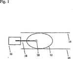
Die Brust
Die
Die
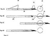
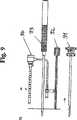
Während der Tomosynthese-Röntgenbestrahlung können metallische Brustbiopsienadeln die entnommene Läsion verdecken oder andere unerwünschte Artefakte verursachen, wie beispielsweise Schlieren- oder Streifenartefakte in den rekonstruierten Tomosyntheseaufnahmen. Dies ist besonders akut, wo die entnommenen Gewebeläsionen Kalzifikationen sind. Diese Verdeckung kann die Exaktheit der Biopsie verringern. Ausführungsformen der vorliegenden Erfindung beinhalten alle Nadelformen, welche eine bessere Sichtbarkeit der entnommenen Gewebeläsion ermöglichen.During x-ray tomosynthesis, metallic breast biopsy needles may obscure the harvested lesion or cause other undesirable artifacts, such as streaking or stripe artifacts in the reconstructed tomosynthesis images. This is especially acute where the extracted tissue lesions are calcifications. This occlusion can reduce the accuracy of the biopsy. Embodiments of the present invention include all needle shapes that allow for better visibility of the harvested tissue lesion.
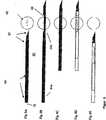
Verschiedene Ausführungsformen derartiger Nadeln sind in den
Die
Die
Die
Zusätzliche Beispiele für Brustbiopsienadeln sind offenbart in den
Demzufolge beschreibt die vorliegende Offenbarung in einem Aspekt ein System, in dem rekonstruierte Tomosyntheseaufnahmen von Schichten einer Patientenbrust und/oder Tomosynthese-Projektionsbilder der Brust verwendet werden, um (1) die Stelle eines verdächtigen interessierenden Bereichs in der Brust zu identifizieren, (2) die Nadelbiopsie des interessierenden Bereichs zu lenken, (3) die Position der Nadel vor dem Vorschießen in Bezug zu dem interessierenden Bereich zu bestätigen und/oder (4) die Position der Nadel nach dem Vorschießen in Bezug zu dem interessierenden Bereich zu bestätigen. Ein einzigartiger Vorteil dieser Herangehensweise ist derjenige bezüglich der verdächtigen pathologischen Veränderungen, die in den Tomosyntheseaufnahmen besser erkannt oder besser bewertet werden können als in den herkömmlichen Mammogrammen oder in den herkömmlichen Ultraschallaufnahmen des Brustgewebes. Das System beinhalten das Aufnehmen einer Serie von Tomosynthese-Projektionsbildern bei den entsprechenden unterschiedlichen Winkeln von dem bildgebenden Röntgenstrahl in Bezug zu der Brust, zum Beispiel in der Weise, die in den Patentanmeldungen offenbart sind, welche in diese Offenbarung durch Verweis aufgenommen wurden. Die Information dieser Projektionsbilder wird zu Aufnahmen der Schichten von der Brust rekonstruiert, welche Schichten ausgewählter Dicke und ausgewählter Winkel im Bezug zu der Brustauflageplatte oder der/den Bildebene(n) der Projektionsbilder repräsentieren. Typischerweise, allerdings nicht zwangsläufig, repräsentieren die rekonstruierten Aufnahmen Schichten, die parallel zu der Brustauflageplatte und somit zu der Ebene eines herkömmlichen Mammogramms sind. Diese Aufnahmen werden zur Identifizierung der Stelle von dem interessierenden Bereich in der Brust in drei Dimensionen verwendet, zum Beispiel, indem der Mediziner auf die Stelle des interessierenden Bereichs in einer oder mehreren Aufnahmen zeigt und das Systems zur Berechnung der 3D-Koordinaten der Stelle in einer Weise verwendet, die ähnlich ist zu derjenigen, die in den vorangehend identifizierten und unter Verweis in diese Offenbarung aufgenommenen Patenten von Biopsiesystemen verwendet wurde, oder auf eine andere Art und Weise, wie etwa durch Deuten auf den interessierenden Bereich in einer rekonstruierten Schichtaufnahme, um dadurch die Position des interessierenden Bereichs in zwei Dimensionen in der Schichtebene zu identifizieren und die dritte Dimension aus der Kenntnis von der Tiefe der Schicht in der Brust bereitzustellen.Accordingly, in one aspect, the present disclosure describes a system in which reconstructed tomosynthesis images of layers of a patient's breast and / or tomosynthesis projection images of the breast are used to (1) (2) To direct the needle biopsy of the area of interest, (3) to confirm the position of the needle before pre-shooting with respect to the area of interest, and / or (4) the position of the needle after pre-shooting in relation to the area of interest. A unique advantage of this approach is that of the suspicious pathological changes that may be better recognized or better assessed in the tomosynthesis recordings than in the conventional mammograms or in the conventional ultrasound images of breast tissue. The system includes capturing a series of tomosynthesis projection images at the respective different angles of the imaging x-ray beam relative to the breast, for example, in the manner disclosed in the patent applications incorporated by reference into this disclosure. The information of these projection images is reconstructed into images of the layers of the breast which represent layers of selected thickness and selected angles with respect to the breastplate or image plane (s) of the projection images. Typically, though not necessarily, the reconstructed images represent layers parallel to the breastplate and thus to the plane of a conventional mammogram. These images are used to identify the location of the region of interest in the breast in three dimensions, for example, by pointing the medical practitioner to the location of interest in one or more images and the system to calculate the 3D coordinates of the site in one A method similar to that used in the patents of biopsy systems previously identified and incorporated by reference in this disclosure, or otherwise, such as by interpreting the region of interest in a reconstructed slice, thereby identify the position of the region of interest in two dimensions in the layer plane and provide the third dimension from the knowledge of the depth of the layer in the breast.
Diese 3D-Information der Lage des interessierenden Bereichs kann zusammen mit der Information bezüglich eines geometrischen Zusammenhangs zu der Ausrüstung, mit welcher die Brust komprimiert und immobilisiert wurde, um die Richtung und das Ausmaß der Bewegung der Biopsienadel, die von der Nadelplattform in einer Weise, die ähnlich ist zu derjenigen, die in den hierin durch Verweis aufgenommenen Patentschriften offenbart ist, zum Positionieren der Nadel, zum Entnehmen einer Probe aus dem interessierenden Bereich und zum Bestätigen der Platzierungen der Nadel vor und nach dem Vorschießen der Nadel in Bezug zu dem interessierenden Bereich ausgeführt wird.This 3D information of the location of the region of interest, together with the information relating to a geometric relationship to the equipment with which the breast has been compressed and immobilized, can be used to determine the direction and extent of movement of the biopsy needle coming from the needle platform in a manner which is similar to that disclosed in the patents incorporated herein by reference, for positioning the needle, removing a sample from the region of interest, and confirming the placement of the needle before and after advancing the needle with respect to the region of interest is performed.
Um unerwünschte Artefakte auf den Röntgenaufnahmen aufgrund des Anwesenheit von für Röntgenstrahlen undurchlässigen Objekten, wie beispielsweise der Biopsienadel in dem bildgebenden Röntgenstrahl, zu verringern, setzt das hierin offenbarte System neue Herangehensweisen ein, entweder einzeln oder in Kombinationen oder in Unterkombinationen miteinander. Eine erste neue Vorgehensweise in diesem Zusammenhang betrifft die Auswahl der Tomosyntheseaufnahmen und beinhaltet das Aufnehmen von Tomosynthese-Projektionsbildern nur bei Winkeln, bei denen die für Röntgenstrahlen undurchlässigen Objekte nicht in dem Röntgenstrahl sind, oder, falls sie im Röntgenstrahl sind, ihre Auswirkung auf die Aufnahme signifikant geringer ist, als es für andere mögliche Strahlenwinkel sein würde. Dies kann beinhalten, keine Projektionsbilder bei Winkeln zu machen, die eher unerwünschte Artefakte produzieren würden und/oder Aufnehmen von derartigen Projektionsbildern, aber sie nicht bei der Rekonstruktion der Schichtaufnahmen zu verwenden. Eine zweite neue Herangehensweise, die anstelle oder zusätzlich zu der ersten verwendet werden kann, ist die Ausführung der Nachbearbeitung der Tomosyntheseaufnahmen, um die darin aufgrund des Vorhandenseins von für Röntgenstrahlen undurchlässigen Objekten in dem Röntgenstrahl vorhandenen Artefakte zu verringern. Dies kann das Bearbeiten der rekonstruierten Schichtaufnahme z. B durch die Verwendung von Algorithmen zur Verringerung von Streifen-Artefakten beinhalten, ähnlich wie sie herkömmlich in der CT-(Computertomografie-)Technologie verwendet wurden und/oder die Bildbearbeitung der Tomosynthese-Projektionsbilder zum Entfernen oder Verringern derartiger Artefakte. Eine dritte neue Herangehensweise, die anstelle von einer oder beiden der ersten und zweiten Herangehensweise oder zusammen mit einer von der ersten oder zweiten verwendet werden kann, ist die Verwendung von einer Biopsieausrüstung, welche derartige Bildartefakte verringert oder vermeidet, z. B. eine Biopsienadel, die mindestens teilweise aus einem material gefertigt wurde, das signifikant durchlässiger ist für Röntgenstrahlen als herkömmliche Biopsienadeln. Eine Nadel, die aus einem derartigen Material hergestellt ist, kann somit für die Einführung in die Brust und für die Entnahme von Gewebeproben verwendet werden oder sie durch Abschnitte eines für Röntgenstrahlen undurchlässigen Materials versteift werden, wie etwa Metall, das für das Einführen und/oder für die Gewebeentnahme eingesetzt wird, allerdings aus der Brust oder zumindest aus der unmittelbaren Umgebung des interessierenden Bereichs zurückgezogen wird, bevor die Röntgenaufnahmen vor und/oder nach Vorschießen der Nadel aufgenommen werden, wodurch die Bildartefakte vermieden werden, die ein derartiges Metall verursachen würde, wenn es nicht zurückgezogen wird. Beispielsweise können derartige versteifende Abschnitte in der Form von Stiften oder Rippen innerhalb einer Kanüle vorliegen. Als weiteres Beispiel können sie als Hülsen koaxial zu einer Kanüle und/oder einem Stilett ausgebildet sein. Andere Bespiele für versteifende Abschnitte, die vor dem Aufnehmen von Aufnahmen vor oder nach Vorschießen der Nadel zurückgezogen werden, sind ebenfalls vorgesehen.To reduce unwanted artifacts on the x-ray images due to the presence of x-ray opaque objects, such as the biopsy needle in the imaging x-ray beam, the system disclosed herein employs new approaches, either singly or in combinations or in subcombinations with each other. A first novel approach in this regard concerns the selection of tomosynthesis recordings and involves taking tomosynthesis projection images only at angles where the X-ray opaque objects are not in the X-ray or, if they are in the X-ray, their impact on the image is significantly less than it would be for other possible beam angles. This may include making no projection images at angles that would rather produce unwanted artifacts and / or capturing such projection images, but not using them in the reconstruction of the slices. A second novel approach, which may be used in lieu of or in addition to the first one, is to perform the post-processing of the tomosynthesis recordings to reduce the artifacts therein due to the presence of x-ray opaque objects in the x-ray beam. This can be the editing of the reconstructed layer recording z. B through the use of algorithms to reduce stripe artifacts similar to those conventionally used in CT (computed tomography) technology and / or image processing of tomosynthesis projection images to remove or reduce such artifacts. A third new approach, which may be used in lieu of either or both of the first and second approaches, or along with one of the first or second, is the use of biopsy equipment which reduces or eliminates such image artifacts, e.g. As a biopsy needle, which was made at least partially of a material that is significantly more transparent to X-rays than conventional biopsy needles. A needle made of such a material may thus be used for insertion into the breast and for taking tissue samples, or stiffened by portions of an X-ray opaque material, such as metal, for insertion and / or insertion but is withdrawn from the chest or at least the immediate vicinity of the area of interest before the x-rays are taken before and / or after advancing the needle, thereby avoiding the image artifacts that such a metal would cause it not is withdrawn. For example, such stiffening portions may be in the form of pins or ribs within a cannula. As another example, they may be formed as sleeves coaxial with a cannula and / or a stylet. Other examples of stiffening sections that are retracted prior to taking pictures before or after needle advance are also contemplated.
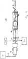
Zusätzliche Ausstattungsmerkmale können hinzugefügt werden. Zum Beispiel kann in dem in
Der Kalzifikations-Detektor
In einem Beispiel (
Für den Fall, dass der Sammelfilter in einem Handgerät oder in einer Nadelplattform in die Biopsienadel integriert ist, würden die Röntgenröhre und der Detektor klein dimensioniert sein. Ein Exemplar eines klein dimensionierten Detektors kann von Hamamatsu, Corporation, Bridgewater, N. J. (siehe
Darüber hinaus kann eine zusätzliche Leitung
Es können viele Variationen der vorangehend diskutierten veranschaulichenden Ausführungsformen und Beispiele eingeführt werden, ohne von dem Geist der Offenbarung oder von dem Geltungsbereich der angehängten Ansprüche abzuweichen. Zum Beispiel können Elemente oder Merkmale der unterschiedlichen Beispiele und veranschaulichenden Ausführungsformen miteinander kombiniert und/oder gegenseitig innerhalb des Geltungsbereichs dieser Offenbarung und der angehängten Ansprüche ausgetauscht werden.Many variations of the illustrative embodiments and examples discussed above may be introduced without departing from the spirit of the disclosure or from the scope of the appended claims. For example, elements or features of the different examples and illustrative embodiments may be combined and / or mutually substituted within the scope of this disclosure and the appended claims.
Diese Anmeldung beansprucht die Priorität der vorläufigen US-Anmeldung Seriennummer 60/774,142, eingereicht am 15. Februar 2006, deren gesamter Inhalt hierin unter Bezugnahme aufgenommen ist.This application claims the benefit of US Provisional Application Serial No. 60 / 774,142, filed on Feb. 15, 2006, the entire contents of which are incorporated herein by reference.
Bezugszeichenliste LIST OF REFERENCE NUMBERS
- 1010
- Kompressionsplattecompression plate
- 1111
- Zugangslochaccess hole
- 1212
- Brustchest
- 1414
- Auflageplatteplaten
- 1616
- Plattformplatform
- 1818
- Nadelneedle
- 2020
- Pathologie/LäsionPathology / lesion
- 2222
- Brustwandchest wall
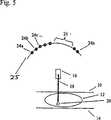
- 2525
- Bogen von RöntgenröhreArch from x-ray tube
- 2626
- übersprungene Regionskipped region
- 3232
- Metallspitzenmetal tips
- 3434
- Nadelschäfte aus für Röntgenstrahlen durchlässigem MaterialNeedle shafts made of X-ray permeable material
- 3838
- mit Kalzifikationen assoziierte Läsionlesion associated with calcification
- 4242
- Metallspitzenmetal tips
- 4444
- Nadelschäfte aus für Röntgenstrahlen durchlässigem Material, umgeben von entfernbaren „Metallknochen” zur Festigung des SchaftesNeedle shafts made of X-ray permeable material, surrounded by removable "metal bones" to strengthen the shaft
- 4848
- mit Kalzifikationen assoziierte Läsionlesion associated with calcification
- 6262
- Metallspitzenmetal tips
- 6464
- Doppelschicht-Schäfte. Jeder besteht aus zwei koaxialen Schichten; eine aus für Röntgenstrahlen durchlässigem Material (z. B. Kunststoff), die andere Schicht aus Metall, was den Schaft während des Vorschießens fest machtDouble-layer shafts. Each consists of two coaxial layers; one out of X-ray transmissive material (eg, plastic), the other layer of metal, which makes the shaft solid during advancing
- 6868
- mit Kalzifikationen assoziierte Läsionlesion associated with calcification
- 9191
- äußere Kanüleouter cannula
- 9292
- LokalisationsobturatorLokalisationsobturator
- 9393
- EinführungsstilettEinführungsstilett
- 9494
- Einführungshülseintroducer sheath
- 101101
- Biopsienadelbiopsy needle
- 102102
- Sammelkammerplenum
- 104104
- KalzifikationsdetektorKalzifikationsdetektor
- 105105
- Betäubungs- und KontrastmittelStun and contrast agents
- 107107
- Vakuumvacuum
ZITATE ENTHALTEN IN DER BESCHREIBUNG QUOTES INCLUDE IN THE DESCRIPTION
Diese Liste der vom Anmelder aufgeführten Dokumente wurde automatisiert erzeugt und ist ausschließlich zur besseren Information des Lesers aufgenommen. Die Liste ist nicht Bestandteil der deutschen Patent- bzw. Gebrauchsmusteranmeldung. Das DPMA übernimmt keinerlei Haftung für etwaige Fehler oder Auslassungen.This list of the documents listed by the applicant has been generated automatically and is included solely for the better information of the reader. The list is not part of the German patent or utility model application. The DPMA assumes no liability for any errors or omissions.
Zitierte PatentliteraturCited patent literature
- US 5078142[0004]US 5078142[0004]
- US 5240011[0004]US 5240011[0004]
- US 5415169[0004]US 5415169[0004]
- US 5735264[0004]US 5735264[0004]
- US 5803912[0004]US 5803912[0004]
- US 6022325[0004]US 6022325[0004]
- US 5289520[0004]US 5289520[0004]
- US 5426685[0004]US 5426685[0004]
- US 5594769[0004]US 5594769[0004]
- US 5609152[0004]US Pat. No. 5,609,152[0004]
- US 6638235[0035]US 6638235[0035]
- US 6758824[0035]US Pat. No. 6758824[0035]
- US 6620111[0035]US 6620111[0035]
- US 6626849[0035]US 6626849[0035]
- US 2006/0155209 A1[0035]US 2006/0155209 A1[0035]
- US 2006/0129062 A1[0035]US 2006/0129062 A1[0035]
- US 2006/0030784 A1[0035]US 2006/0030784 A1[0035]
- US 2005/0113715 A1[0035]US 2005/0113715 A1[0035]
- US 2005/0049521 A1[0035]US 2005/0049521 Al[0035]
- US 2004/0267157 A1[0035]US 2004/0267157 A1[0035]
Zitierte Nicht-PatentliteraturCited non-patent literature
- http://sales.hamamatsu.com/en/products/electron-tube-division/x-ray-produ-cts/x-ray-flat-panel-sensor.php[0042]http://sales.hamamatsu.com/en/products/electron-tube-division/x-ray-produ-cts/x-ray-flat-panel-sensor.php[0042]
- http://www.newtonscientificinc.com/swans.htm[0042]http://www.newtonscientificinc.com/swans.htm[0042]
Claims (8)
Translated fromGermanApplications Claiming Priority (2)
| Application Number | Priority Date | Filing Date | Title |
|---|---|---|---|
| US77414206P | 2006-02-15 | 2006-02-15 | |
| US60/774,142 | 2006-02-15 |
Publications (1)
| Publication Number | Publication Date |
|---|---|
| DE202007019497U1true DE202007019497U1 (en) | 2013-03-06 |
Family
ID=38372135
Family Applications (1)
| Application Number | Title | Priority Date | Filing Date |
|---|---|---|---|
| DE202007019497UExpired - LifetimeDE202007019497U1 (en) | 2006-02-15 | 2007-02-15 | Breast biopsy and needle localization using tomosynthesis systems |
Country Status (5)
| Country | Link |
|---|---|
| US (6) | US8532745B2 (en) |
| EP (1) | EP1986548B1 (en) |
| JP (1) | JP5554927B2 (en) |
| DE (1) | DE202007019497U1 (en) |
| WO (1) | WO2007095330A2 (en) |
Families Citing this family (149)
| Publication number | Priority date | Publication date | Assignee | Title |
|---|---|---|---|---|
| US8109885B2 (en) | 2002-03-19 | 2012-02-07 | C. R. Bard, Inc. | Biopsy device for removing tissue specimens using a vacuum |
| EP1524940B1 (en) | 2002-03-19 | 2011-08-24 | Bard Dublin ITC Limited | Biopsy device and biopsy needle module that can be inserted into the biopsy device |
| US8565372B2 (en) | 2003-11-26 | 2013-10-22 | Hologic, Inc | System and method for low dose tomosynthesis |
| US7616801B2 (en) | 2002-11-27 | 2009-11-10 | Hologic, Inc. | Image handling and display in x-ray mammography and tomosynthesis |
| US8571289B2 (en) | 2002-11-27 | 2013-10-29 | Hologic, Inc. | System and method for generating a 2D image from a tomosynthesis data set |
| US7123684B2 (en)* | 2002-11-27 | 2006-10-17 | Hologic, Inc. | Full field mammography with tissue exposure control, tomosynthesis, and dynamic field of view processing |
| US7577282B2 (en) | 2002-11-27 | 2009-08-18 | Hologic, Inc. | Image handling and display in X-ray mammography and tomosynthesis |
| US10638994B2 (en) | 2002-11-27 | 2020-05-05 | Hologic, Inc. | X-ray mammography with tomosynthesis |
| DE10314240B4 (en) | 2003-03-29 | 2025-05-28 | Bard Dublin Itc Ltd. | Pressure generation unit |
| JP4814229B2 (en) | 2004-07-09 | 2011-11-16 | バード ペリフェラル ヴァスキュラー インコーポレイテッド | Transport device for biopsy device |
| US7662082B2 (en) | 2004-11-05 | 2010-02-16 | Theragenics Corporation | Expandable brachytherapy device |
| US7702142B2 (en) | 2004-11-15 | 2010-04-20 | Hologic, Inc. | Matching geometry generation and display of mammograms and tomosynthesis images |
| EP1816965B1 (en) | 2004-11-26 | 2016-06-29 | Hologic, Inc. | Integrated multi-mode mammography/tomosynthesis x-ray system |
| US7517321B2 (en) | 2005-01-31 | 2009-04-14 | C. R. Bard, Inc. | Quick cycle biopsy system |
| JP4991723B2 (en) | 2005-08-10 | 2012-08-01 | シー・アール・バード・インコーポレーテッド | Single insertion multiple sampling biopsy device with integrated marker |
| ES2539578T3 (en) | 2005-08-10 | 2015-07-02 | C.R. Bard, Inc. | Multi-sample biopsy device and single insert with various transport systems |
| EP1921998B8 (en) | 2005-08-10 | 2021-07-07 | C.R.Bard, Inc. | Single-insertion, multiple sampling biopsy device with linear drive |
| US7465268B2 (en) | 2005-11-18 | 2008-12-16 | Senorx, Inc. | Methods for asymmetrical irradiation of a body cavity |
| WO2007095330A2 (en) | 2006-02-15 | 2007-08-23 | Hologic Inc | Breast biopsy and needle localization using tomosynthesis systems |
| US8386013B2 (en)* | 2006-04-13 | 2013-02-26 | The Regents Of The University Of California | Magnetic resonance imaging (MRI) using ultra short echo times and spiral sampling in K-space |
| US8120358B2 (en) | 2006-04-13 | 2012-02-21 | The Regents Of The University Of California | Magnetic resonance imaging with high spatial and temporal resolution |
| EP3417792B1 (en) | 2006-08-21 | 2022-03-02 | C. R. Bard, Inc. | Self-contained handheld biopsy needle |
| SI2086418T1 (en) | 2006-10-06 | 2011-05-31 | Bard Peripheral Vascular Inc | Tissue handling system with reduced operator exposure |
| US8262586B2 (en) | 2006-10-24 | 2012-09-11 | C. R. Bard, Inc. | Large sample low aspect ratio biopsy needle |
| CN101534715B (en) | 2006-11-10 | 2012-01-11 | 皇家飞利浦电子股份有限公司 | Metal artefact prevention during needle guidance under (xper) ct |
| US20080221478A1 (en)* | 2007-03-07 | 2008-09-11 | Ritchie Paul G | Integrated Imaging and Biopsy System with Integrated Control Interface |
| US7602184B2 (en)* | 2007-04-30 | 2009-10-13 | The Regents Of The University Of California | Magnetic resonance spectroscopic imaging with short echo times |
| US7630533B2 (en) | 2007-09-20 | 2009-12-08 | Hologic, Inc. | Breast tomosynthesis with display of highlighted suspected calcifications |
| US8241225B2 (en) | 2007-12-20 | 2012-08-14 | C. R. Bard, Inc. | Biopsy device |
| US7854706B2 (en) | 2007-12-27 | 2010-12-21 | Devicor Medical Products, Inc. | Clutch and valving system for tetherless biopsy device |
| DE102008006358A1 (en)* | 2008-01-28 | 2009-07-30 | Siemens Aktiengesellschaft | X-ray image recording method and apparatus for stereotactic biopsy |
| US20090253997A1 (en)* | 2008-04-03 | 2009-10-08 | Convergent Medical Solutions, Inc. | Skin biopsy with automated lesion stabilization and resection |
| US7792245B2 (en) | 2008-06-24 | 2010-09-07 | Hologic, Inc. | Breast tomosynthesis system with shifting face shield |
| US7991106B2 (en) | 2008-08-29 | 2011-08-02 | Hologic, Inc. | Multi-mode tomosynthesis/mammography gain calibration and image correction using gain map information from selected projection angles |
| US8942342B2 (en)* | 2008-12-29 | 2015-01-27 | Analogic Corporation | Multi-modality image acquisition |
| US9579524B2 (en) | 2009-02-11 | 2017-02-28 | Hologic, Inc. | Flexible multi-lumen brachytherapy device |
| US9248311B2 (en) | 2009-02-11 | 2016-02-02 | Hologic, Inc. | System and method for modifying a flexibility of a brachythereapy catheter |
| WO2010107424A1 (en) | 2009-03-16 | 2010-09-23 | C.R. Bard, Inc. | Biopsy device having rotational cutting |
| JP5346654B2 (en)* | 2009-03-31 | 2013-11-20 | キヤノン株式会社 | Radiation imaging apparatus and control method thereof |
| JP5373450B2 (en)* | 2009-03-31 | 2013-12-18 | 富士フイルム株式会社 | Biopsy device and method of operating biopsy device |
| JP5334657B2 (en)* | 2009-04-14 | 2013-11-06 | 富士フイルム株式会社 | Radiation image processing apparatus and method, and program |
| AU2009344276B2 (en) | 2009-04-15 | 2014-06-05 | C.R. Bard, Inc. | Biopsy apparatus having integrated fluid management |
| US10207126B2 (en) | 2009-05-11 | 2019-02-19 | Cytyc Corporation | Lumen visualization and identification system for multi-lumen balloon catheter |
| US8206316B2 (en) | 2009-06-12 | 2012-06-26 | Devicor Medical Products, Inc. | Tetherless biopsy device with reusable portion |
| US8529468B2 (en) | 2009-07-01 | 2013-09-10 | Suros Surgical Systems, Inc. | Surgical system |
| JP5355271B2 (en)* | 2009-07-24 | 2013-11-27 | 富士フイルム株式会社 | Radiation imaging equipment |
| US9173641B2 (en) | 2009-08-12 | 2015-11-03 | C. R. Bard, Inc. | Biopsy apparatus having integrated thumbwheel mechanism for manual rotation of biopsy cannula |
| US8430824B2 (en) | 2009-10-29 | 2013-04-30 | Bard Peripheral Vascular, Inc. | Biopsy driver assembly having a control circuit for conserving battery power |
| US8485989B2 (en) | 2009-09-01 | 2013-07-16 | Bard Peripheral Vascular, Inc. | Biopsy apparatus having a tissue sample retrieval mechanism |
| ES2862525T3 (en)* | 2009-10-08 | 2021-10-07 | Hologic Inc | Needle Breast Biopsy System and Method of Use |
| US8597206B2 (en) | 2009-10-12 | 2013-12-03 | Bard Peripheral Vascular, Inc. | Biopsy probe assembly having a mechanism to prevent misalignment of components prior to installation |
| US8597201B2 (en) | 2010-03-30 | 2013-12-03 | Siteselect Medical Technologies, Inc. | Tissue excision device with a flexible transection blade |
| FR2959409B1 (en) | 2010-05-03 | 2012-06-29 | Gen Electric | METHOD FOR DETERMINING A TOOL INSERTION PATH IN A DEFORMABLE TISSUE MATRIX AND ROBOTIC SYSTEM USING THE METHOD |
| JP5986994B2 (en)* | 2010-06-28 | 2016-09-06 | コーニンクレッカ フィリップス エヌ ヴェKoninklijke Philips N.V. | Medical tomosynthesis system |
| DE102010031737A1 (en)* | 2010-07-21 | 2012-01-26 | Siemens Aktiengesellschaft | Device for tissue removal |
| DE102010031738A1 (en)* | 2010-07-21 | 2012-01-26 | Siemens Aktiengesellschaft | Image assisted biopsy removal |
| JP5650467B2 (en) | 2010-08-27 | 2015-01-07 | 富士フイルム株式会社 | Radiation imaging system |
| US9352172B2 (en) | 2010-09-30 | 2016-05-31 | Hologic, Inc. | Using a guide member to facilitate brachytherapy device swap |
| CA2813591C (en) | 2010-10-05 | 2020-09-22 | Hologic, Inc. | Upright x-ray breast imaging with a ct mode, multiple tomosynthesis modes, and a mammography mode |
| US9730659B2 (en) | 2010-11-16 | 2017-08-15 | Analogic Corporation | Multi-modality image acquisition |
| US9492130B2 (en) | 2010-11-24 | 2016-11-15 | Hologic, Inc. | System for improved tissue-handling and in line analysis of the tissue |
| US20120133600A1 (en) | 2010-11-26 | 2012-05-31 | Hologic, Inc. | User interface for medical image review workstation |
| US10342992B2 (en) | 2011-01-06 | 2019-07-09 | Hologic, Inc. | Orienting a brachytherapy applicator |
| JP6057922B2 (en) | 2011-03-08 | 2017-01-11 | ホロジック, インコーポレイテッドHologic, Inc. | System and method for dual energy and / or contrast enhanced breast imaging for screening, diagnosis and biopsy |
| US20120245486A1 (en)* | 2011-03-25 | 2012-09-27 | Anthony Melchiorri | Ghost-core biopsy needle |
| JP5743684B2 (en)* | 2011-04-27 | 2015-07-01 | 富士フイルム株式会社 | Radiographic imaging apparatus and method of operating radiographic imaging apparatus |
| JP5864891B2 (en)* | 2011-04-27 | 2016-02-17 | 富士フイルム株式会社 | Radiation imaging equipment |
| JP5806847B2 (en)* | 2011-04-27 | 2015-11-10 | 富士フイルム株式会社 | Radiographic imaging apparatus and method of operating radiographic imaging apparatus |
| JP5638466B2 (en)* | 2011-06-02 | 2014-12-10 | 富士フイルム株式会社 | Image generating apparatus, radiographic image capturing system, image generating program, and image generating method |
| ES2795416T3 (en) | 2011-09-16 | 2020-11-23 | Hologic Inc | Lateral Arm System for Breast Biopsy |
| US11284869B2 (en) | 2011-09-16 | 2022-03-29 | Hologic, Inc. | Breast biopsy lateral arm system |
| US12042134B2 (en) | 2011-09-16 | 2024-07-23 | Hologic, Inc. | Breast biopsy lateral arm system |
| JP6157491B2 (en) | 2011-11-18 | 2017-07-05 | ホロジック, インコーポレイテッドHologic, Inc. | X-ray mammography and / or breast tomosynthesis using a compression paddle with an inflatable jacket to improve contrast and patient comfort |
| US11259759B2 (en) | 2011-11-18 | 2022-03-01 | Hologic Inc. | X-ray mammography and/or breast tomosynthesis using a compression paddle |
| EP2782505B1 (en) | 2011-11-27 | 2020-04-22 | Hologic, Inc. | System and method for generating a 2d image using mammography and/or tomosynthesis image data |
| JP6240097B2 (en) | 2012-02-13 | 2017-11-29 | ホロジック インコーポレイティッド | How to navigate a tomosynthesis stack using composite image data |
| EP2852352B1 (en)* | 2012-05-04 | 2021-09-01 | Roger Khouri | Surgical tools |
| US20130345550A1 (en)* | 2012-06-25 | 2013-12-26 | Tzachi Rafaeli | Systems and methods for localizing an opaque medical device with nuclear medicine imaging |
| CN105451657A (en) | 2013-03-15 | 2016-03-30 | 霍罗吉克公司 | System and method for navigating tomosynthesis stack including automatic focusing |
| US10092358B2 (en) | 2013-03-15 | 2018-10-09 | Hologic, Inc. | Tomosynthesis-guided biopsy apparatus and method |
| CA2902221A1 (en) | 2013-03-20 | 2014-09-25 | Bard Peripheral Vascular, Inc. | Biopsy device |
| CN113768529A (en)* | 2013-04-26 | 2021-12-10 | 蒂莫西·R·斯坦戈 | X-ray breast imaging system and compression paddle for X-ray breast imaging system |
| CA2925907C (en) | 2013-10-09 | 2022-03-15 | Hologic, Inc. | X-ray breast tomosynthesis enhancing spatial resolution including in the thickness direction of a flattened breast |
| CN103593869B (en)* | 2013-10-12 | 2016-08-10 | 沈阳东软医疗系统有限公司 | A kind of scanning device and method for displaying image thereof |
| EP3060132B1 (en) | 2013-10-24 | 2019-12-04 | Hologic, Inc. | System and method for navigating x-ray guided breast biopsy |
| ES2726985T3 (en) | 2013-11-05 | 2019-10-11 | Bard Inc C R | Biopsy device that has integrated vacuum |
| JP6506769B2 (en) | 2014-02-28 | 2019-04-24 | ホロジック, インコーポレイテッドHologic, Inc. | System and method for generating and displaying tomosynthesis image slabs |
| WO2015147009A1 (en)* | 2014-03-28 | 2015-10-01 | 富士フイルム株式会社 | Radiological image photography system, radiological image photography method, and radiological image photography program |
| JP6162324B2 (en)* | 2014-03-28 | 2017-07-12 | 富士フイルム株式会社 | Radiographic imaging system, radiographic imaging method, and radiographic imaging program |
| US20170049503A1 (en)* | 2014-05-15 | 2017-02-23 | Cosman Medical, Inc. | Electrosurgical system |
| US9713450B2 (en) | 2014-12-15 | 2017-07-25 | General Electric Company | Iterative reconstruction of projection data |
| JP6275030B2 (en) | 2014-12-24 | 2018-02-07 | 富士フイルム株式会社 | Biopsy device and method of operating the same |
| US10568694B2 (en) | 2015-04-22 | 2020-02-25 | General Electric Company | Method and system for performing a guided biopsy using digital tomosynthesis |
| WO2016178656A1 (en) | 2015-05-01 | 2016-11-10 | C. R. Bard, Inc. | Biopsy device |
| WO2017040977A1 (en) | 2015-09-04 | 2017-03-09 | Faxitron Bioptics, Llc | Multi-axis specimen imaging device with embedded orientation markers |
| WO2017059078A1 (en) | 2015-09-30 | 2017-04-06 | Devicor Medical Products, Inc. | Breast support compression pillow |
| WO2017185028A1 (en) | 2016-04-22 | 2017-10-26 | Hologic, Inc. | Tomosynthesis with shifting focal spot x-ray system using an addressable array |
| US10157460B2 (en) | 2016-10-25 | 2018-12-18 | General Electric Company | Interpolated tomosynthesis projection images |
| US11083426B2 (en) | 2016-11-04 | 2021-08-10 | Hologic, Inc. | Specimen radiography system comprising cabinet and a specimen drawer positionable by a controller in the cabinet |
| US10096106B2 (en) | 2016-11-10 | 2018-10-09 | General Electric Company | Combined medical imaging |
| EP3413801B1 (en)* | 2016-11-15 | 2020-01-08 | Koninklijke Philips N.V. | Apparatus for tomosynthesis image reconstruction |
| US10463333B2 (en)* | 2016-12-13 | 2019-11-05 | General Electric Company | Synthetic images for biopsy control |
| EP3378401B1 (en) | 2017-03-23 | 2025-02-12 | Siemens Healthineers AG | Representation of an area of interest |
| EP3600052A1 (en) | 2017-03-30 | 2020-02-05 | Hologic, Inc. | System and method for targeted object enhancement to generate synthetic breast tissue images |
| EP3600047A1 (en) | 2017-03-30 | 2020-02-05 | Hologic, Inc. | System and method for hierarchical multi-level feature image synthesis and representation |
| CN110621233B (en) | 2017-03-30 | 2023-12-12 | 豪洛捷公司 | Method for processing breast tissue image data |
| CA3062311A1 (en) | 2017-05-03 | 2018-11-08 | Hologic, Inc. | Device for reducing fluid in the imaging field of a tissue handling apparatus for improving biopsy system imaging quality |
| US12279901B2 (en) | 2017-05-03 | 2025-04-22 | 3Dio, Inc. | Three dimensional X-ray imaging system |
| EP3618718A4 (en) | 2017-05-03 | 2020-11-11 | Turner Innovations, LLC | THREE-DIMENSIONAL X-RAY IMAGING SYSTEM |
| US11116483B2 (en) | 2017-05-19 | 2021-09-14 | Merit Medical Systems, Inc. | Rotating biopsy needle |
| US11844500B2 (en) | 2017-05-19 | 2023-12-19 | Merit Medical Systems, Inc. | Semi-automatic biopsy needle device and methods of use |
| US11793498B2 (en) | 2017-05-19 | 2023-10-24 | Merit Medical Systems, Inc. | Biopsy needle devices and methods of use |
| JP6937163B2 (en)* | 2017-05-29 | 2021-09-22 | キヤノンメディカルシステムズ株式会社 | Mammography device and puncture support system |
| WO2018236565A1 (en) | 2017-06-20 | 2018-12-27 | Hologic, Inc. | METHOD AND SYSTEM FOR MEDICAL IMAGING WITH DYNAMIC SELF-LEARNING |
| US11672493B2 (en) | 2017-08-11 | 2023-06-13 | Hologic, Inc. | Breast compression paddle with access corners |
| US11439360B2 (en)* | 2017-08-16 | 2022-09-13 | Hologic, Inc. | Medical procedure draping system |
| EP4129188A1 (en) | 2017-08-16 | 2023-02-08 | Hologic, Inc. | Techniques for breast imaging patient motion artifact compensation |
| EP3449835B1 (en) | 2017-08-22 | 2023-01-11 | Hologic, Inc. | Computed tomography system and method for imaging multiple anatomical targets |
| WO2019112998A1 (en)* | 2017-12-05 | 2019-06-13 | Devicor Medical Products, Inc. | Biopsy device with applied imaging |
| WO2019126180A1 (en)* | 2017-12-19 | 2019-06-27 | Devicor Medical Products, Inc. | Tissue collection and processing cassette with applied imaging |
| US12121304B2 (en) | 2018-05-04 | 2024-10-22 | Hologic, Inc. | Introducer and localization wire visualization |
| EP3787520B1 (en) | 2018-05-04 | 2024-09-25 | Hologic, Inc. | Biopsy needle visualization |
| US11596368B2 (en) | 2018-05-25 | 2023-03-07 | Hologic, Inc. | Breast compression paddles utilizing pivoting foam elements |
| US20190388152A1 (en)* | 2018-06-21 | 2019-12-26 | General Electric Company | System and method for contact management of a biopsy apparatus |
| US11090017B2 (en) | 2018-09-13 | 2021-08-17 | Hologic, Inc. | Generating synthesized projection images for 3D breast tomosynthesis or multi-mode x-ray breast imaging |
| WO2020068851A1 (en) | 2018-09-24 | 2020-04-02 | Hologic, Inc. | Breast mapping and abnormality localization |
| WO2020068767A1 (en) | 2018-09-28 | 2020-04-02 | Hologic, Inc. | System and method for synthetic breast tissue image generation by high density element suppression |
| WO2020107019A1 (en) | 2018-11-25 | 2020-05-28 | Hologic, Inc. | Multimodality hanging protocols |
| DE202020006044U1 (en) | 2019-03-29 | 2024-07-02 | Hologic Inc. | Report generation for cropped digital images |
| US11883206B2 (en) | 2019-07-29 | 2024-01-30 | Hologic, Inc. | Personalized breast imaging system |
| EP4439580A3 (en) | 2019-09-27 | 2024-12-25 | Hologic, Inc. | Ai system for predicting reading time and reading complexity for reviewing 2d/3d breast images |
| US12295556B2 (en) | 2019-09-27 | 2025-05-13 | Merit Medical Systems, Inc. | Rotation biopsy system and handle |
| EP3832689A3 (en) | 2019-12-05 | 2021-08-11 | Hologic, Inc. | Systems and methods for improved x-ray tube life |
| US12150627B2 (en) | 2019-12-11 | 2024-11-26 | Merit Medical Systems, Inc. | Bone biopsy device and related methods |
| JP7742349B2 (en) | 2020-01-24 | 2025-09-19 | ホロジック, インコーポレイテッド | Horizontally displaceable foam breast compression paddles |
| US11514624B2 (en)* | 2020-03-16 | 2022-11-29 | GE Precision Healthcare LLC | Methods and systems for biopsy needle reconstruction error assessment |
| US11471118B2 (en) | 2020-03-27 | 2022-10-18 | Hologic, Inc. | System and method for tracking x-ray tube focal spot position |
| KR20220158719A (en) | 2020-03-27 | 2022-12-01 | 홀로직, 인크. | Systems and methods for measuring deflection of a foam breast compression paddle |
| US11481038B2 (en) | 2020-03-27 | 2022-10-25 | Hologic, Inc. | Gesture recognition in controlling medical hardware or software |
| JP7629025B2 (en) | 2020-03-31 | 2025-02-12 | ホロジック, インコーポレイテッド | System and method for x-ray imaging of tissue samples - Patents.com |
| EP4214672B1 (en) | 2020-09-16 | 2025-01-01 | Hologic, Inc. | Systems and methods for confirming tissue specimens removed using contrast-enhanced x-ray imaging |
| JP7674860B2 (en)* | 2021-03-08 | 2025-05-12 | キヤノンメディカルシステムズ株式会社 | Diagnosis Support System |
| US11786191B2 (en) | 2021-05-17 | 2023-10-17 | Hologic, Inc. | Contrast-enhanced tomosynthesis with a copper filter |
| CN113662594B (en)* | 2021-09-10 | 2024-04-23 | 上海联影医疗科技股份有限公司 | Breast puncture positioning/biopsy method, device, computer equipment and storage medium |
| US12186119B2 (en) | 2021-10-05 | 2025-01-07 | Hologic, Inc. | Interactive model interface for image selection in medical imaging systems |
| US12254586B2 (en) | 2021-10-25 | 2025-03-18 | Hologic, Inc. | Auto-focus tool for multimodality image review |
| WO2023097279A1 (en) | 2021-11-29 | 2023-06-01 | Hologic, Inc. | Systems and methods for correlating objects of interest |
| US12414217B2 (en) | 2022-02-07 | 2025-09-09 | Hologic, Inc. | Systems and methods for adaptively controlling filament current in an X-ray tube |
| WO2024091430A1 (en)* | 2022-10-27 | 2024-05-02 | Devicor Medical Products, Inc. | Detection of calcification in a targeted breast biopsy tissue |
Citations (9)
| Publication number | Priority date | Publication date | Assignee | Title |
|---|---|---|---|---|
| US5078142A (en) | 1989-11-21 | 1992-01-07 | Fischer Imaging Corporation | Precision mammographic needle biopsy system |
| US5240011A (en) | 1991-11-27 | 1993-08-31 | Fischer Imaging Corporation | Motorized biopsy needle positioner |
| US5289520A (en) | 1991-11-27 | 1994-02-22 | Lorad Corporation | Stereotactic mammography imaging system with prone position examination table and CCD camera |
| US5415169A (en) | 1989-11-21 | 1995-05-16 | Fischer Imaging Corporation | Motorized mammographic biopsy apparatus |
| US5594769A (en) | 1991-11-27 | 1997-01-14 | Thermotrex Corporation | Method and apparatus for obtaining stereotactic mammographic guided needle breast biopsies |
| US6620111B2 (en) | 2001-04-20 | 2003-09-16 | Ethicon Endo-Surgery, Inc. | Surgical biopsy device having automatic rotation of the probe for taking multiple samples |
| US6626849B2 (en) | 2001-11-01 | 2003-09-30 | Ethicon Endo-Surgery, Inc. | MRI compatible surgical biopsy device |
| US6638235B2 (en) | 2000-11-06 | 2003-10-28 | Suros Surgical Systems, Inc. | Biopsy apparatus |
| US20050113715A1 (en) | 2000-11-06 | 2005-05-26 | Jeffrey Schwindt | Biopsy apparatus |
Family Cites Families (492)
| Publication number | Priority date | Publication date | Assignee | Title |
|---|---|---|---|---|
| JP4054402B2 (en) | 1997-04-25 | 2008-02-27 | 株式会社東芝 | X-ray tomography equipment |
| US3502878A (en) | 1967-09-22 | 1970-03-24 | Us Health Education & Welfare | Automatic x-ray apparatus for limiting the field size of a projected x-ray beam in response to film size and to source-to-film distance |
| US7050611B2 (en) | 2001-05-29 | 2006-05-23 | Mevis Breastcare Gmbh Co. Kg | Method and computer system for screening of medical cases |
| US3863073A (en) | 1973-04-26 | 1975-01-28 | Machlett Lab Inc | Automatic system for precise collimation of radiation |
| US3971950A (en) | 1975-04-14 | 1976-07-27 | Xerox Corporation | Independent compression and positioning device for use in mammography |
| US4160906A (en) | 1977-06-23 | 1979-07-10 | General Electric Company | Anatomically coordinated user dominated programmer for diagnostic x-ray apparatus |
| DE2838901C2 (en) | 1978-09-06 | 1986-11-06 | Siemens AG, 1000 Berlin und 8000 München | Catapult drawer |
| DE2945057C2 (en)* | 1979-11-08 | 1984-06-07 | Philips Patentverwaltung Gmbh, 2000 Hamburg | Process for reducing image defects in layer images of a three-dimensional object produced with the aid of penetrating radiation |
| FR2512024A1 (en) | 1981-08-27 | 1983-03-04 | Adir | TRICYCLIC ETHERS, PREPARATION THEREOF AND PHARMACEUTICAL COMPOSITIONS CONTAINING THEM |
| FR2549248B1 (en) | 1983-06-24 | 1986-01-31 | Thomson Csf | RETRACTABLE CASSETTE HOLDER FOR RADIOLOGICAL AND RADIOGRAPHIC EXAMINATION APPARATUS |
| DE3339775A1 (en) | 1983-11-03 | 1985-05-15 | Siemens AG, 1000 Berlin und 8000 München | X-RAY DIAGNOSTIC DEVICE WITH RADIATION FILTERS |
| SE8306243L (en)* | 1983-11-14 | 1985-05-15 | Cytex Medicinteknik Ab | LOCATION METHODOLOGY |
| JPS60129034A (en) | 1983-12-16 | 1985-07-10 | 横河メディカルシステム株式会社 | Operation table of x-ray tomographic apparatus |
| US4559557A (en) | 1984-06-01 | 1985-12-17 | General Electric Company | Region-of-interest digital subtraction angiography |
| US4706269A (en) | 1985-03-11 | 1987-11-10 | Reina Leo J | Anti-scatter grid structure |
| US4773087A (en) | 1986-04-14 | 1988-09-20 | University Of Rochester | Quality of shadowgraphic x-ray images |
| USRE33634E (en) | 1986-09-23 | 1991-07-09 | Method and structure for optimizing radiographic quality by controlling X-ray tube voltage, current focal spot size and exposure time | |
| US4821727A (en) | 1986-10-30 | 1989-04-18 | Elscint Ltd. | Mammographic biopsy needle holder system |
| US4819258A (en) | 1986-11-28 | 1989-04-04 | Bennett X-Ray Corp. | Auto-setting of KV in an x-ray machine after selection of technic factors |
| US4907156A (en) | 1987-06-30 | 1990-03-06 | University Of Chicago | Method and system for enhancement and detection of abnormal anatomic regions in a digital image |
| US5051904A (en) | 1988-03-24 | 1991-09-24 | Olganix Corporation | Computerized dynamic tomography system |
| US5740270A (en) | 1988-04-08 | 1998-04-14 | Neuromedical Systems, Inc. | Automated cytological specimen classification system and method |
| DK654488A (en) | 1988-11-23 | 1990-05-24 | Nordisk Roentgen Tech App | ROENTGENAPPARAT |
| US5099846A (en) | 1988-12-23 | 1992-03-31 | Hardy Tyrone L | Method and apparatus for video presentation from a variety of scanner imaging sources |
| FR2645006A1 (en) | 1989-03-29 | 1990-10-05 | Gen Electric Cgr | MAMMOGRAPH HAVING INTEGRATED STEREOTAXIC VIEWING DEVICE AND METHOD OF USING SUCH A MAMMOGRAPHER |
| FR2646340A1 (en) | 1989-04-28 | 1990-11-02 | Gen Electric Cgr | ADJUSTABLE CASSETTE HOLDER IN DIMENSION AND POSITION FOR MAMMOGRAPHY |
| DE58908415D1 (en) | 1989-07-03 | 1994-10-27 | Siemens Ag | X-ray diagnostic device for mammography images. |
| US5133020A (en) | 1989-07-21 | 1992-07-21 | Arch Development Corporation | Automated method and system for the detection and classification of abnormal lesions and parenchymal distortions in digital medical images |
| CA2014918A1 (en) | 1989-09-06 | 1991-03-06 | James A. Mcfaul | Scanning mammography system with improved skin line viewing |
| US4969174A (en) | 1989-09-06 | 1990-11-06 | General Electric Company | Scanning mammography system with reduced scatter radiation |
| US5280427A (en)* | 1989-11-27 | 1994-01-18 | Bard International, Inc. | Puncture guide for computer tomography |
| US5199056A (en) | 1989-11-28 | 1993-03-30 | Darrah Carol J | Mammography compression paddle |
| US5481623A (en) | 1990-04-19 | 1996-01-02 | Fuji Photo Film Co., Ltd. | Apparatus for determining an image position on imaging media |
| FR2668359B1 (en) | 1990-10-24 | 1998-02-20 | Gen Electric Cgr | MAMMOGRAPH PROVIDED WITH A PERFECTED NEEDLE HOLDER. |
| US5129911A (en) | 1991-03-11 | 1992-07-14 | Siczek Bernard W | Orbital aiming device |
| US5409497A (en) | 1991-03-11 | 1995-04-25 | Fischer Imaging Corporation | Orbital aiming device for mammo biopsy |
| US5279309A (en) | 1991-06-13 | 1994-01-18 | International Business Machines Corporation | Signaling device and method for monitoring positions in a surgical operation |
| US5163075A (en) | 1991-08-08 | 1992-11-10 | Eastman Kodak Company | Contrast enhancement of electrographic imaging |
| US5941832A (en) | 1991-09-27 | 1999-08-24 | Tumey; David M. | Method and apparatus for detection of cancerous and precancerous conditions in a breast |
| US5343390A (en) | 1992-02-28 | 1994-08-30 | Arch Development Corporation | Method and system for automated selection of regions of interest and detection of septal lines in digital chest radiographs |
| US5359637A (en) | 1992-04-28 | 1994-10-25 | Wake Forest University | Self-calibrated tomosynthetic, radiographic-imaging system, method, and device |
| US5386447A (en) | 1992-09-23 | 1995-01-31 | Fischer Imaging Corporation | Mammographic screening and biopsy apparatus |
| US5596200A (en) | 1992-10-14 | 1997-01-21 | Primex | Low dose mammography system |
| FR2703237B1 (en) | 1993-03-29 | 1995-05-19 | Ge Medical Syst Sa | Mammograph equipped with a stereotaxic camera with digital detector and method of using such a mammograph. |
| US5491627A (en) | 1993-05-13 | 1996-02-13 | Arch Development Corporation | Method and system for the detection of microcalcifications in digital mammograms |
| US5878746A (en) | 1993-08-25 | 1999-03-09 | Lemelson; Jerome H. | Computerized medical diagnostic system |
| US5365562A (en) | 1993-09-20 | 1994-11-15 | Fischer Imaging Corporation | Digital imaging apparatus |
| US6075879A (en) | 1993-09-29 | 2000-06-13 | R2 Technology, Inc. | Method and system for computer-aided lesion detection using information from multiple images |
| US5526394A (en) | 1993-11-26 | 1996-06-11 | Fischer Imaging Corporation | Digital scan mammography apparatus |
| US5452367A (en) | 1993-11-29 | 1995-09-19 | Arch Development Corporation | Automated method and system for the segmentation of medical images |
| CA2113752C (en) | 1994-01-19 | 1999-03-02 | Stephen Michael Rooks | Inspection system for cross-sectional imaging |
| DE4414689C2 (en) | 1994-04-26 | 1996-08-29 | Siemens Ag | X-ray diagnostic device |
| US5499097A (en) | 1994-09-19 | 1996-03-12 | Neopath, Inc. | Method and apparatus for checking automated optical system performance repeatability |
| US5557097A (en) | 1994-09-20 | 1996-09-17 | Neopath, Inc. | Cytological system autofocus integrity checking apparatus |
| US5647025A (en) | 1994-09-20 | 1997-07-08 | Neopath, Inc. | Automatic focusing of biomedical specimens apparatus |
| AU3371395A (en) | 1994-09-20 | 1996-04-19 | Neopath, Inc. | Biological specimen analysis system processing integrity checking apparatus |
| US5553111A (en) | 1994-10-26 | 1996-09-03 | The General Hospital Corporation | Apparatus and method for improved tissue imaging |
| US5712890A (en) | 1994-11-23 | 1998-01-27 | Thermotrex Corp. | Full breast digital mammography device |
| US5506877A (en) | 1994-11-23 | 1996-04-09 | The General Hospital Corporation | Mammography breast compression device and method |
| US5657362A (en) | 1995-02-24 | 1997-08-12 | Arch Development Corporation | Automated method and system for computerized detection of masses and parenchymal distortions in medical images |
| US5660185A (en) | 1995-04-13 | 1997-08-26 | Neovision Corporation | Image-guided biopsy apparatus with enhanced imaging and methods |
| US5671288A (en) | 1995-05-31 | 1997-09-23 | Neopath, Inc. | Method and apparatus for assessing slide and specimen preparation quality |
| US6216540B1 (en) | 1995-06-06 | 2001-04-17 | Robert S. Nelson | High resolution device and method for imaging concealed objects within an obscuring medium |
| JPH10505286A (en) | 1995-06-20 | 1998-05-26 | シン ング、ワン | Articulated arm for medical procedures |
| JP3617698B2 (en) | 1995-07-17 | 2005-02-09 | 東芝医用システムエンジニアリング株式会社 | Diagnosis support device |
| US5642433A (en) | 1995-07-31 | 1997-06-24 | Neopath, Inc. | Method and apparatus for image contrast quality evaluation |
| US5642441A (en) | 1995-10-24 | 1997-06-24 | Neopath, Inc. | Separation apparatus and method for measuring focal plane |
| US5818898A (en) | 1995-11-07 | 1998-10-06 | Kabushiki Kaisha Toshiba | X-ray imaging apparatus using X-ray planar detector |
| US5693948A (en) | 1995-11-21 | 1997-12-02 | Loral Fairchild Corporation | Advanced CCD-based x-ray image sensor system |
| US5627869A (en) | 1995-11-22 | 1997-05-06 | Thermotrex Corporation | Mammography apparatus with proportional collimation |
| FI955636A0 (en) | 1995-11-23 | 1995-11-23 | Planmed Oy | Foerfarande och system Foer styrning av funktionerna av en mammografiaanordning |
| US5709206A (en) | 1995-11-27 | 1998-01-20 | Teboul; Michel | Imaging system for breast sonography |
| EP1300713A3 (en) | 1995-11-30 | 2004-11-03 | Chromavision Medical Systems, Inc. | Method and apparatus for automated image analysis of biological specimens |
| US5769086A (en)* | 1995-12-06 | 1998-06-23 | Biopsys Medical, Inc. | Control system and method for automated biopsy device |
| JPH09198490A (en) | 1996-01-22 | 1997-07-31 | Hitachi Medical Corp | Three-dimensional discrete data projector |
| JPH09238934A (en) | 1996-03-11 | 1997-09-16 | Toshiba Medical Eng Co Ltd | Image display system |
| DE19619924A1 (en) | 1996-05-17 | 1997-11-20 | Siemens Ag | Tomosynthetic image generating method |
| DE19619925C2 (en) | 1996-05-17 | 1999-09-09 | Sirona Dental Systems Gmbh | X-ray diagnostic device for tomosynthesis |
| DE19619915A1 (en) | 1996-05-17 | 1997-11-20 | Siemens Ag | Process for creating tomosynthesis images |
| DE19619913C2 (en) | 1996-05-17 | 2001-03-15 | Sirona Dental Systems Gmbh | X-ray diagnostic device for tomosynthesis |
| US6067079A (en) | 1996-06-13 | 2000-05-23 | International Business Machines Corporation | Virtual pointing device for touchscreens |
| US5835079A (en) | 1996-06-13 | 1998-11-10 | International Business Machines Corporation | Virtual pointing device for touchscreens |
| US5841124A (en) | 1996-06-19 | 1998-11-24 | Neopath, Inc. | Cytological system autofocus integrity checking apparatus |
| US5872828A (en) | 1996-07-23 | 1999-02-16 | The General Hospital Corporation | Tomosynthesis system for breast imaging |
| JPH1033523A (en) | 1996-07-24 | 1998-02-10 | Hitachi Medical Corp | X-ray ct device |
| US5776062A (en) | 1996-10-15 | 1998-07-07 | Fischer Imaging Corporation | Enhanced breast imaging/biopsy system employing targeted ultrasound |
| US5986662A (en) | 1996-10-16 | 1999-11-16 | Vital Images, Inc. | Advanced diagnostic viewer employing automated protocol selection for volume-rendered imaging |
| US6293282B1 (en) | 1996-11-05 | 2001-09-25 | Jerome Lemelson | System and method for treating select tissue in living being |
| JP3878259B2 (en) | 1996-11-13 | 2007-02-07 | 東芝医用システムエンジニアリング株式会社 | Medical image processing device |
| US6137527A (en) | 1996-12-23 | 2000-10-24 | General Electric Company | System and method for prompt-radiology image screening service via satellite |
| US5757880A (en) | 1997-01-08 | 1998-05-26 | Colomb; Denis | Apparatus, article of manufacture, and method for creation of an uncompressed image of compressed matter |
| SE9700117D0 (en)* | 1997-01-17 | 1997-01-17 | Siemens Elema Ab | A method for modifying at least one computational algorithm for a biopsy system and a biopsy system |
| US7117098B1 (en) | 1997-02-27 | 2006-10-03 | Cellomics, Inc. | Machine-readable storage medium for analyzing distribution of macromolecules between the cell membrane and the cell cytoplasm |
| US5999639A (en) | 1997-09-04 | 1999-12-07 | Qualia Computing, Inc. | Method and system for automated detection of clustered microcalcifications from digital mammograms |
| US6091981A (en) | 1997-09-16 | 2000-07-18 | Assurance Medical Inc. | Clinical tissue examination |
| US20030135115A1 (en)* | 1997-11-24 | 2003-07-17 | Burdette Everette C. | Method and apparatus for spatial registration and mapping of a biopsy needle during a tissue biopsy |
| US6442288B1 (en) | 1997-12-17 | 2002-08-27 | Siemens Aktiengesellschaft | Method for reconstructing a three-dimensional image of an object scanned in the context of a tomosynthesis, and apparatus for tomosynthesis |
| JP3554172B2 (en) | 1998-01-09 | 2004-08-18 | キヤノン株式会社 | Radiography equipment |
| US6175117B1 (en) | 1998-01-23 | 2001-01-16 | Quanta Vision, Inc. | Tissue analysis apparatus |
| US6289235B1 (en) | 1998-03-05 | 2001-09-11 | Wake Forest University | Method and system for creating three-dimensional images using tomosynthetic computed tomography |
| US6081577A (en) | 1998-07-24 | 2000-06-27 | Wake Forest University | Method and system for creating task-dependent three-dimensional images |
| US6375352B1 (en) | 1999-10-01 | 2002-04-23 | General Electric Company | Apparatus and method for obtaining x-ray tomosynthesis data for mammography |
| US6141398A (en) | 1998-08-25 | 2000-10-31 | General Electric Company | Protocol driven image reconstruction, display, and processing in a multislice imaging system |
| US6101236A (en)* | 1998-10-02 | 2000-08-08 | University Of Iowa Research Foundation | Iterative method and apparatus for x-ray computed tomographic fluoroscopy |
| EP1143845A4 (en)* | 1998-11-25 | 2004-10-06 | Fischer Imaging Corp | User interface system for mammographic imager |
| FR2786388B1 (en) | 1998-11-27 | 2001-02-16 | Ge Medical Syst Sa | METHOD FOR DETECTING FABRIC OF A SPECIFIC NATURE IN DIGITAL RADIOLOGY AND ITS USE FOR ADJUSTING THE EXPOSURE PARAMETERS |
| US6149301A (en) | 1998-12-30 | 2000-11-21 | General Electric Company | X-ray target centering apparatus for radiographic imaging system |
| JP2000200340A (en) | 1999-01-06 | 2000-07-18 | Ge Yokogawa Medical Systems Ltd | Method and device for displaying image and ct system |
| WO2000048286A1 (en) | 1999-01-29 | 2000-08-17 | American Superconductor Corporation | Electric utility system with superconducting magnetic energy storage |
| US6424332B1 (en) | 1999-01-29 | 2002-07-23 | Hunter Innovations, Inc. | Image comparison apparatus and method |
| US6233473B1 (en) | 1999-02-16 | 2001-05-15 | Hologic, Inc. | Determining body composition using fan beam dual-energy x-ray absorptiometry |
| US6272207B1 (en) | 1999-02-18 | 2001-08-07 | Creatv Microtech, Inc. | Method and apparatus for obtaining high-resolution digital X-ray and gamma ray images |
| US6256370B1 (en) | 2000-01-24 | 2001-07-03 | General Electric Company | Method and apparatus for performing tomosynthesis |
| FR2792749B1 (en)* | 1999-04-22 | 2001-06-01 | Ge Medical Syst Sa | METHOD OF LOCATING AND THREE-DIMENSIONAL REPRESENTATION OF ELEMENTS OF INTEREST OF AN ORGAN |
| US6689142B1 (en) | 1999-04-26 | 2004-02-10 | Scimed Life Systems, Inc. | Apparatus and methods for guiding a needle |
| US6292530B1 (en) | 1999-04-29 | 2001-09-18 | General Electric Company | Method and apparatus for reconstructing image data acquired by a tomosynthesis x-ray imaging system |
| DE19922346C2 (en) | 1999-05-14 | 2003-06-18 | Siemens Ag | X-ray diagnostic device for tomosynthesis or layering |
| US6243441B1 (en) | 1999-07-13 | 2001-06-05 | Edge Medical Devices | Active matrix detector for X-ray imaging |
| US20020173721A1 (en) | 1999-08-20 | 2002-11-21 | Novasonics, Inc. | User interface for handheld imaging devices |
| US6480565B1 (en) | 1999-11-18 | 2002-11-12 | University Of Rochester | Apparatus and method for cone beam volume computed tomography breast imaging |
| US6987831B2 (en) | 1999-11-18 | 2006-01-17 | University Of Rochester | Apparatus and method for cone beam volume computed tomography breast imaging |
| US6245028B1 (en)* | 1999-11-24 | 2001-06-12 | Marconi Medical Systems, Inc. | Needle biopsy system |
| US6633674B1 (en) | 1999-11-24 | 2003-10-14 | General Electric Company | Picture archiving and communication system employing improved data compression |
| US6645520B2 (en) | 1999-12-16 | 2003-11-11 | Dermatrends, Inc. | Transdermal administration of nonsteroidal anti-inflammatory drugs using hydroxide-releasing agents as permeation enhancers |
| FR2803069B1 (en) | 1999-12-28 | 2002-12-13 | Ge Medical Syst Sa | METHOD AND SYSTEM FOR COMPENSATING THE THICKNESS OF AN ORGAN |
| US6411836B1 (en) | 1999-12-30 | 2002-06-25 | General Electric Company | Method and apparatus for user preferences configuring in an image handling system |
| US8352289B2 (en) | 1999-12-30 | 2013-01-08 | Dhi Computing, Inc. | Systems and methods for providing and maintaining electronic medical records |
| US6901156B2 (en) | 2000-02-04 | 2005-05-31 | Arch Development Corporation | Method, system and computer readable medium for an intelligent search workstation for computer assisted interpretation of medical images |
| DE10005628B4 (en)* | 2000-02-09 | 2006-04-20 | Siemens Ag | Method and device for aligning a medical instrument on the body of a patient using a computer tomograph |
| US6744848B2 (en) | 2000-02-11 | 2004-06-01 | Brandeis University | Method and system for low-dose three-dimensional imaging of a scene |
| GB0006598D0 (en) | 2000-03-17 | 2000-05-10 | Isis Innovation | Three-dimensional reconstructions from images |
| US6351660B1 (en) | 2000-04-18 | 2002-02-26 | Litton Systems, Inc. | Enhanced visualization of in-vivo breast biopsy location for medical documentation |
| JP4750922B2 (en)* | 2000-04-27 | 2011-08-17 | 株式会社東芝 | Radiation diagnostic equipment |
| US6327336B1 (en) | 2000-06-05 | 2001-12-04 | Direct Radiography Corp. | Radiogram showing location of automatic exposure control sensor |
| US6683934B1 (en) | 2000-06-05 | 2004-01-27 | General Electric Company | Dual energy x-ray imaging system and method for radiography and mammography |
| US6389104B1 (en) | 2000-06-30 | 2002-05-14 | Siemens Corporate Research, Inc. | Fluoroscopy based 3-D neural navigation based on 3-D angiography reconstruction data |
| JP2002052018A (en) | 2000-08-11 | 2002-02-19 | Canon Inc | Image display device, image display method, and storage medium |
| JP2002109510A (en) | 2000-09-27 | 2002-04-12 | Fuji Photo Film Co Ltd | Possible abnormal shadow detecting and processing system |
| EP1267722A1 (en) | 2000-10-20 | 2003-01-02 | Koninklijke Philips Electronics N.V. | Tomosynthesis in a limited angular range |
| US6468226B1 (en) | 2000-11-22 | 2002-10-22 | Mcintyre, Iv John J. | Remote tissue biopsy apparatus and associated methods |
| US7556602B2 (en) | 2000-11-24 | 2009-07-07 | U-Systems, Inc. | Breast cancer screening with adjunctive ultrasound mammography |
| US7597663B2 (en) | 2000-11-24 | 2009-10-06 | U-Systems, Inc. | Adjunctive ultrasound processing and display for breast cancer screening |
| US7615008B2 (en) | 2000-11-24 | 2009-11-10 | U-Systems, Inc. | Processing and displaying breast ultrasound information |
| US7103205B2 (en) | 2000-11-24 | 2006-09-05 | U-Systems, Inc. | Breast cancer screening with ultrasound image overlays |
| US6650928B1 (en) | 2000-11-27 | 2003-11-18 | Ge Medical Systems Global Technology Company, Llc | Color parametric and composite maps for CT perfusion |
| US6501819B2 (en) | 2000-12-18 | 2002-12-31 | Ge Medical Systems Global Technology Company, Llc | Medical diagnostic method and apparatus to control dual energy exposure techniques based on image information |
| FR2818116B1 (en) | 2000-12-19 | 2004-08-27 | Ge Med Sys Global Tech Co Llc | MAMMOGRAPHY APPARATUS |
| US6463181B2 (en) | 2000-12-22 | 2002-10-08 | The United States Of America As Represented By The Secretary Of The Navy | Method for optimizing visual display of enhanced digital images |
| EP1346322A1 (en) | 2000-12-22 | 2003-09-24 | Koninklijke Philips Electronics N.V. | Stereoscopic viewing of a region between clipping planes |
| CA2437454A1 (en) | 2001-02-01 | 2002-08-22 | Creatv Microtech, Inc. | Anti-scatter grids and collimator designs, and their motion, fabrication and assembly |
| US7030861B1 (en) | 2001-02-10 | 2006-04-18 | Wayne Carl Westerman | System and method for packing multi-touch gestures onto a hand |
| US6486764B2 (en) | 2001-02-16 | 2002-11-26 | Delphi Technologies, Inc. | Rotary position sensor |
| US20020188466A1 (en) | 2001-04-18 | 2002-12-12 | Barrette Pierre Philip | Secure digital medical intellectual property (IP) distribution, market applications, and mobile devices |
| US6965793B2 (en)* | 2001-06-28 | 2005-11-15 | Chemimage Corporation | Method for Raman chemical imaging of endogenous chemicals to reveal tissue lesion boundaries in tissue |
| US6611575B1 (en) | 2001-07-27 | 2003-08-26 | General Electric Company | Method and system for high resolution 3D visualization of mammography images |
| WO2003017244A1 (en) | 2001-08-17 | 2003-02-27 | Multidigit, Inc. | System and method for selecting actions based on the identification of user's fingers |
| WO2003020114A2 (en) | 2001-08-31 | 2003-03-13 | Analogic Corporation | Image positioning method and system for tomosynthesis in a digital x-ray radiography system |
| FR2829918A1 (en) | 2001-09-25 | 2003-03-28 | Ge Med Sys Global Tech Co Llc | Imaging method in mammography apparatus, involves moving compression paddle in compression position, in projection to different directions perpendicular to X-ray propagation direction |
| US20030072478A1 (en) | 2001-10-12 | 2003-04-17 | Claus Bernhard Erich Hermann | Reconstruction method for tomosynthesis |
| US7443949B2 (en) | 2001-10-19 | 2008-10-28 | Hologic, Inc. | Mammography system and method employing offset compression paddles, automatic collimation, and retractable anti-scatter grid |
| DE60135559D1 (en) | 2001-11-19 | 2008-10-09 | St Microelectronics Srl | Method for mixing digital images to produce a digital image with extended dynamic range |
| US20030097055A1 (en) | 2001-11-21 | 2003-05-22 | Philips Medical Systems(Cleveland), Inc. | Method of reviewing tomographic scans with a large number of images |
| US6751285B2 (en) | 2001-11-21 | 2004-06-15 | General Electric Company | Dose management system for mammographic tomosynthesis |
| US6895077B2 (en) | 2001-11-21 | 2005-05-17 | University Of Massachusetts Medical Center | System and method for x-ray fluoroscopic imaging |
| JP4099984B2 (en) | 2001-12-14 | 2008-06-11 | コニカミノルタホールディングス株式会社 | Abnormal shadow detection apparatus and image output apparatus |
| US6978040B2 (en) | 2001-12-19 | 2005-12-20 | Canon Kabushiki Kaisha | Optical recovery of radiographic geometry |
| US6647092B2 (en) | 2002-01-18 | 2003-11-11 | General Electric Company | Radiation imaging system and method of collimation |
| SE524458C2 (en) | 2002-03-01 | 2004-08-10 | Mamea Imaging Ab | Protective device by an X-ray apparatus |
| WO2003077202A1 (en) | 2002-03-06 | 2003-09-18 | Siemens Corporate Research, Inc. | Visualization of volume-volume fusion |
| US7346381B2 (en) | 2002-11-01 | 2008-03-18 | Ge Medical Systems Global Technology Company Llc | Method and apparatus for medical intervention procedure planning |
| US6878115B2 (en) | 2002-03-28 | 2005-04-12 | Ultrasound Detection Systems, Llc | Three-dimensional ultrasound computed tomography imaging system |
| US6819790B2 (en) | 2002-04-12 | 2004-11-16 | The University Of Chicago | Massive training artificial neural network (MTANN) for detecting abnormalities in medical images |
| US6707878B2 (en) | 2002-04-15 | 2004-03-16 | General Electric Company | Generalized filtered back-projection reconstruction in digital tomosynthesis |
| US20030194050A1 (en) | 2002-04-15 | 2003-10-16 | General Electric Company | Multi modality X-ray and nuclear medicine mammography imaging system and method |
| US6882700B2 (en) | 2002-04-15 | 2005-04-19 | General Electric Company | Tomosynthesis X-ray mammogram system and method with automatic drive system |
| US7218766B2 (en) | 2002-04-15 | 2007-05-15 | General Electric Company | Computer aided detection (CAD) for 3D digital mammography |
| US6752767B2 (en)* | 2002-04-16 | 2004-06-22 | Vivant Medical, Inc. | Localization element with energized tip |
| US7139000B2 (en) | 2002-05-13 | 2006-11-21 | Ge Medical Systems Global Technology Company, Llc | Method, system and computer product for displaying axial images |
| US7295691B2 (en) | 2002-05-15 | 2007-11-13 | Ge Medical Systems Global Technology Company, Llc | Computer aided diagnosis of an image set |
| US11275405B2 (en) | 2005-03-04 | 2022-03-15 | Apple Inc. | Multi-functional hand-held device |
| US7599579B2 (en) | 2002-07-11 | 2009-10-06 | Ge Medical Systems Global Technology Company, Llc | Interpolated image filtering method and apparatus |
| US7450747B2 (en) | 2002-07-12 | 2008-11-11 | Ge Medical Systems Global Technology Company, Llc | System and method for efficiently customizing an imaging system |
| US7406666B2 (en) | 2002-08-26 | 2008-07-29 | Palm, Inc. | User-interface features for computers with contact-sensitive displays |
| US6898331B2 (en) | 2002-08-28 | 2005-05-24 | Bae Systems Aircraft Controls, Inc. | Image fusion system and method |
| US6748044B2 (en) | 2002-09-13 | 2004-06-08 | Ge Medical Systems Global Technology Company, Llc | Computer assisted analysis of tomographic mammography data |
| US6574304B1 (en) | 2002-09-13 | 2003-06-03 | Ge Medical Systems Global Technology Company, Llc | Computer aided acquisition of medical images |
| US7260249B2 (en) | 2002-09-27 | 2007-08-21 | Confirma Incorporated | Rules-based approach for processing medical images |
| US7347829B2 (en)* | 2002-10-07 | 2008-03-25 | Suros Surgical Systems, Inc. | Introduction system for minimally invasive surgical instruments |
| US6940943B2 (en) | 2002-10-07 | 2005-09-06 | General Electric Company | Continuous scan tomosynthesis system and method |
| US6825838B2 (en) | 2002-10-11 | 2004-11-30 | Sonocine, Inc. | 3D modeling system |
| US20040171933A1 (en) | 2002-11-25 | 2004-09-02 | Milton Stoller | Mammography needle biopsy system and method |
| US7123684B2 (en) | 2002-11-27 | 2006-10-17 | Hologic, Inc. | Full field mammography with tissue exposure control, tomosynthesis, and dynamic field of view processing |
| US7760924B2 (en) | 2002-11-27 | 2010-07-20 | Hologic, Inc. | System and method for generating a 2D image from a tomosynthesis data set |
| US6597762B1 (en) | 2002-11-27 | 2003-07-22 | Ge Medical Systems Global Technology Co., Llc | Method and apparatus of lesion detection and validation based on multiple reviews of a CT image |
| US8571289B2 (en) | 2002-11-27 | 2013-10-29 | Hologic, Inc. | System and method for generating a 2D image from a tomosynthesis data set |
| US7616801B2 (en) | 2002-11-27 | 2009-11-10 | Hologic, Inc. | Image handling and display in x-ray mammography and tomosynthesis |
| US7831296B2 (en) | 2002-11-27 | 2010-11-09 | Hologic, Inc. | X-ray mammography with tomosynthesis |
| US7577282B2 (en) | 2002-11-27 | 2009-08-18 | Hologic, Inc. | Image handling and display in X-ray mammography and tomosynthesis |
| US7406150B2 (en) | 2002-11-29 | 2008-07-29 | Hologic, Inc. | Distributed architecture for mammographic image acquisition and processing |
| US7904824B2 (en) | 2002-12-10 | 2011-03-08 | Siemens Medical Solutions Usa, Inc. | Medical imaging programmable custom user interface system and method |
| US7110490B2 (en) | 2002-12-10 | 2006-09-19 | General Electric Company | Full field digital tomosynthesis method and apparatus |
| EP1430835B1 (en) | 2002-12-17 | 2011-11-16 | Kabushiki Kaisha Toshiba | System for peripheral X-ray angiography |
| US7286634B2 (en) | 2002-12-23 | 2007-10-23 | Select Technologies, Llc | Method and apparatus for improving baggage screening examination |
| US7356113B2 (en) | 2003-02-12 | 2008-04-08 | Brandeis University | Tomosynthesis imaging system and method |
| JP4604451B2 (en) | 2003-02-24 | 2011-01-05 | コニカミノルタホールディングス株式会社 | Medical image processing apparatus and malignancy determination method |
| US6999553B2 (en) | 2003-03-04 | 2006-02-14 | Livingston Products, Inc. | Method and apparatus for x-ray mammography imaging |
| US7333644B2 (en) | 2003-03-11 | 2008-02-19 | Siemens Medical Solutions Usa, Inc. | Systems and methods for providing automatic 3D lesion segmentation and measurements |
| EP1620003B1 (en) | 2003-05-06 | 2015-04-15 | Victor John Yannacone, Jr. | System and method for identifying and classifying dynamic thermodynamic processes in mammals and discriminating between and among such processes |
| JP4497837B2 (en) | 2003-05-12 | 2010-07-07 | キヤノン株式会社 | Radiation imaging equipment |
| WO2005001740A2 (en) | 2003-06-25 | 2005-01-06 | Siemens Medical Solutions Usa, Inc. | Systems and methods for automated diagnosis and decision support for breast imaging |
| US6885724B2 (en) | 2003-08-22 | 2005-04-26 | Ge Medical Systems Global Technology Company, Llc | Radiographic tomosynthesis image acquisition utilizing asymmetric geometry |
| US8090164B2 (en) | 2003-08-25 | 2012-01-03 | The University Of North Carolina At Chapel Hill | Systems, methods, and computer program products for analysis of vessel attributes for diagnosis, disease staging, and surgical planning |
| US7424141B2 (en) | 2003-08-29 | 2008-09-09 | Agilent Technologies, Inc. | System and method for performing auto-focused tomosynthesis |
| US7578781B2 (en) | 2003-09-18 | 2009-08-25 | Wisconsin Alumni Research Foundation | Device for placement of needles and radioactive seeds in radiotherapy |
| WO2005028681A1 (en) | 2003-09-19 | 2005-03-31 | Arcturus Bioscience, Inc. | Predicting breast cancer treatment outcome |
| JP2005110843A (en) | 2003-10-06 | 2005-04-28 | Canon Inc | Radiation image processing apparatus and processing method |
| US7869862B2 (en) | 2003-10-15 | 2011-01-11 | Varian Medical Systems, Inc. | Systems and methods for functional imaging using contrast-enhanced multiple-energy computed tomography |
| US20050089205A1 (en) | 2003-10-23 | 2005-04-28 | Ajay Kapur | Systems and methods for viewing an abnormality in different kinds of images |
| US20050113680A1 (en) | 2003-10-29 | 2005-05-26 | Yoshihiro Ikeda | Cerebral ischemia diagnosis assisting apparatus, X-ray computer tomography apparatus, and apparatus for aiding diagnosis and treatment of acute cerebral infarct |
| JP2005149107A (en) | 2003-11-14 | 2005-06-09 | Konica Minolta Medical & Graphic Inc | Medical image management system |
| DE10353611B4 (en) | 2003-11-17 | 2013-01-17 | Siemens Aktiengesellschaft | X-ray diagnostic device for mammography examinations |
| US8768026B2 (en) | 2003-11-26 | 2014-07-01 | Hologic, Inc. | X-ray imaging with x-ray markers that provide adjunct information but preserve image quality |
| JP4739225B2 (en) | 2003-11-26 | 2011-08-03 | コーニンクレッカ フィリップス エレクトロニクス エヌ ヴィ | Workflow optimization for high-throughput imaging environments |
| US8265728B2 (en) | 2003-11-26 | 2012-09-11 | University Of Chicago | Automated method and system for the evaluation of disease and registration accuracy in the subtraction of temporally sequential medical images |
| US7727151B2 (en) | 2003-11-28 | 2010-06-01 | U-Systems Inc. | Navigation among multiple breast ultrasound volumes |
| US7773721B2 (en)* | 2003-12-03 | 2010-08-10 | The General Hospital Corporation | Multi-segment cone-beam reconstruction system and method for tomosynthesis imaging |
| AU2003289401A1 (en) | 2003-12-17 | 2005-07-05 | Seijiro Tomita | Individual authentication system using cardiac sound waveform and/or breathing waveform pattern |
| US7653229B2 (en) | 2003-12-23 | 2010-01-26 | General Electric Company | Methods and apparatus for reconstruction of volume data from projection data |
| US20050135555A1 (en) | 2003-12-23 | 2005-06-23 | Claus Bernhard Erich H. | Method and system for simultaneously viewing rendered volumes |
| CN1933787A (en) | 2004-01-23 | 2007-03-21 | 特拉克斯医疗有限公司 | Methods and apparatus for performing procedures on target locations in the body |
| JP2005227350A (en) | 2004-02-10 | 2005-08-25 | Olympus Corp | Electric revolver controller and program for controlling electric revolver |
| US7298881B2 (en) | 2004-02-13 | 2007-11-20 | University Of Chicago | Method, system, and computer software product for feature-based correlation of lesions from multiple images |
| US7289825B2 (en) | 2004-03-15 | 2007-10-30 | General Electric Company | Method and system for utilizing wireless voice technology within a radiology workflow |
| US7142633B2 (en) | 2004-03-31 | 2006-11-28 | General Electric Company | Enhanced X-ray imaging system and method |
| US7699783B2 (en) | 2004-04-08 | 2010-04-20 | Techniscan, Inc. | Method for imaging and treating a breast |
| EP1750584B1 (en) | 2004-05-14 | 2020-10-14 | Philips Intellectual Property & Standards GmbH | System and method for diagnosing breast cancer |
| GB0411402D0 (en) | 2004-05-21 | 2004-06-23 | Tissuomics Ltd | Penetrating radiation measurements |
| AU2005266901B2 (en) | 2004-07-23 | 2010-04-08 | Learning Tree International | System and method for electronic presentations |
| US7835562B2 (en) | 2004-07-23 | 2010-11-16 | General Electric Company | Methods and apparatus for noise reduction filtering of images |
| FR2873835A1 (en) | 2004-07-29 | 2006-02-03 | Gen Electric | METHOD AND DEVICE FOR X-RAY IMAGING WITH CONTRAST PRODUCT FOR ENHANCED VISUALIZATION |
| US7323692B2 (en) | 2004-08-10 | 2008-01-29 | Research Foundation Of State University Of New York | Flat-panel detector with avalanche gain |
| US7725153B2 (en) | 2004-10-04 | 2010-05-25 | Hologic, Inc. | Estimating visceral fat by dual-energy x-ray absorptiometry |
| WO2006042077A2 (en) | 2004-10-09 | 2006-04-20 | Viatronix Incorporated | Sampling medical images for virtual histology |
| WO2006055251A2 (en) | 2004-11-02 | 2006-05-26 | Metrohealth System | Method and apparatus for determining correlation between spatial coordinates in breast |
| US7702142B2 (en) | 2004-11-15 | 2010-04-20 | Hologic, Inc. | Matching geometry generation and display of mammograms and tomosynthesis images |
| EP1816965B1 (en)* | 2004-11-26 | 2016-06-29 | Hologic, Inc. | Integrated multi-mode mammography/tomosynthesis x-ray system |
| US20060132508A1 (en) | 2004-12-16 | 2006-06-22 | Navid Sadikali | Multi-planar image viewing system and method |
| US20090005693A1 (en) | 2004-12-22 | 2009-01-01 | Biotree Systems, Inc. | Medical Imaging Methods and Apparatus for Diagnosis and Monitoring of Diseases and Uses Therefor |
| US7616793B2 (en) | 2004-12-30 | 2009-11-10 | Hologic, Inc. | Medical image review workstation with integrated content-based resource retrieval |
| US9760214B2 (en) | 2005-02-23 | 2017-09-12 | Zienon, Llc | Method and apparatus for data entry input |
| US7859549B2 (en) | 2005-03-08 | 2010-12-28 | Agfa Inc. | Comparative image review system and method |
| US20060210131A1 (en) | 2005-03-15 | 2006-09-21 | Wheeler Frederick W Jr | Tomographic computer aided diagnosis (CAD) with multiple reconstructions |
| US8373652B2 (en) | 2005-04-06 | 2013-02-12 | Kabushiki Kaisha Toshiba | Image display apparatus and image display method |
| JP5038643B2 (en) | 2005-04-06 | 2012-10-03 | 株式会社東芝 | Image display device |
| US10492749B2 (en) | 2005-05-03 | 2019-12-03 | The Regents Of The University Of California | Biopsy systems for breast computed tomography |
| DE102005022543A1 (en) | 2005-05-17 | 2006-11-23 | Siemens Ag | Mammography procedure and mammography device |
| JP3891442B2 (en) | 2005-05-25 | 2007-03-14 | 株式会社日立メディコ | 3D image processing method |
| EP1893077A4 (en) | 2005-06-02 | 2011-02-09 | Medipattern Corp | SYSTEM AND METHOD FOR COMPUTER-ASSISTED DETECTION |
| US7606801B2 (en) | 2005-06-07 | 2009-10-20 | Varonis Inc. | Automatic management of storage access control |
| US7809175B2 (en) | 2005-07-01 | 2010-10-05 | Hologic, Inc. | Displaying and navigating computer-aided detection results on a review workstation |
| US20070014468A1 (en) | 2005-07-12 | 2007-01-18 | Gines David L | System and method for confidence measures for mult-resolution auto-focused tomosynthesis |
| US7245694B2 (en) | 2005-08-15 | 2007-07-17 | Hologic, Inc. | X-ray mammography/tomosynthesis of patient's breast |
| US7764820B2 (en) | 2005-08-24 | 2010-07-27 | The General Hospital Corporation | Multi-threshold peripheral equalization method and apparatus for digital mammography and breast tomosynthesis |
| WO2007027610A2 (en) | 2005-08-30 | 2007-03-08 | Bruce Reiner | Multi-functional navigational device and method |
| DE202005013910U1 (en) | 2005-09-02 | 2005-11-24 | Siemens Ag | Mammography unit has face shield moving within X-ray source head to provide withdrawn, protruding and transport positions |
| US20070052700A1 (en) | 2005-09-07 | 2007-03-08 | Wheeler Frederick W | System and method for 3D CAD using projection images |
| US10008184B2 (en) | 2005-11-10 | 2018-06-26 | Hologic, Inc. | System and method for generating a 2D image using mammography and/or tomosynthesis image data |
| US7342233B2 (en) | 2005-11-18 | 2008-03-11 | Sectra Mamea Ab | Method and arrangement relating to x-ray imaging |
| US20070118400A1 (en) | 2005-11-22 | 2007-05-24 | General Electric Company | Method and system for gesture recognition to drive healthcare applications |
| US20070236490A1 (en) | 2005-11-25 | 2007-10-11 | Agfa-Gevaert | Medical image display and review system |
| US20150258271A1 (en) | 2005-12-01 | 2015-09-17 | Dr. Susan Love Research Foundation | Methods of assessing intraductal disease |
| JP2009522005A (en) | 2005-12-29 | 2009-06-11 | ケアストリーム ヘルス インク | Cross-time and cross-modality medical diagnosis |
| US7581399B2 (en) | 2006-01-05 | 2009-09-01 | United Technologies Corporation | Damped coil pin for attachment hanger hinge |
| US20070156451A1 (en) | 2006-01-05 | 2007-07-05 | Gering David T | System and method for portable display of relevant healthcare information |
| WO2007095330A2 (en) | 2006-02-15 | 2007-08-23 | Hologic Inc | Breast biopsy and needle localization using tomosynthesis systems |
| FR2897461A1 (en) | 2006-02-16 | 2007-08-17 | Gen Electric | X-RAY DEVICE AND IMAGE PROCESSING METHOD |
| US20070223651A1 (en) | 2006-03-21 | 2007-09-27 | Wagenaar Douglas J | Dual modality mammography device |
| US7489761B2 (en) | 2006-03-27 | 2009-02-10 | Hologic, Inc. | Breast compression for digital mammography, tomosynthesis and other modalities |
| DE602007012886D1 (en) | 2006-04-12 | 2011-04-14 | Nassir Navab | VIRTUAL PENETRATING MIRROR FOR VISUALIZING VIRTUAL OBJECTS IN ANGIOGRAPHIC APPLICATIONS |
| US8471866B2 (en) | 2006-05-05 | 2013-06-25 | General Electric Company | User interface and method for identifying related information displayed in an ultrasound system |
| US7945083B2 (en) | 2006-05-25 | 2011-05-17 | Carestream Health, Inc. | Method for supporting diagnostic workflow from a medical imaging apparatus |
| FR2902218A1 (en) | 2006-06-07 | 2007-12-14 | Gen Electric | METHOD FOR PROCESSING TOMOSYNTHESIS IMAGES FOR DETECTION OF RADIOLOGICAL SIGNS |
| JP2007330334A (en) | 2006-06-12 | 2007-12-27 | Toshiba Corp | X-ray imaging apparatus and method thereof |
| US7974924B2 (en) | 2006-07-19 | 2011-07-05 | Mvisum, Inc. | Medical data encryption for communication over a vulnerable system |
| CN100444800C (en) | 2006-07-25 | 2008-12-24 | 倪湘申 | X-ray puncture positioning device and method for microtrauma operation |
| US20090080602A1 (en) | 2006-08-03 | 2009-03-26 | Kenneth Brooks | Dedicated breast radiation imaging/therapy system |
| US20080043905A1 (en) | 2006-08-21 | 2008-02-21 | Bamdad Hassanpourgol | Portable Prone Stereotactic Mammography System for Biopsies, Image Guided Lumpectomies, and Radiation Treatment |
| JP2008068032A (en) | 2006-09-15 | 2008-03-27 | Toshiba Corp | Image display device |
| US20080139896A1 (en) | 2006-10-13 | 2008-06-12 | Siemens Medical Solutions Usa, Inc. | System and Method for Graphical Annotation of Anatomical Images Using a Touch Screen Display |
| US7991105B2 (en) | 2006-10-17 | 2011-08-02 | Koninklijke Philips Electronics N.V. | Visualization of 3D images in combination with 2D projection images |
| WO2008050823A1 (en) | 2006-10-26 | 2008-05-02 | Hitachi Medical Corporation | Medical image display device |
| JP4851296B2 (en) | 2006-10-26 | 2012-01-11 | 富士フイルム株式会社 | Radiation tomographic image acquisition apparatus and radiation tomographic image acquisition method |
| US20080114614A1 (en) | 2006-11-15 | 2008-05-15 | General Electric Company | Methods and systems for healthcare application interaction using gesture-based interaction enhanced with pressure sensitivity |
| US8280488B2 (en) | 2006-11-24 | 2012-10-02 | Huisman Henkjan J | Processing and displaying dynamic contrast-enhanced magnetic resonance imaging information |
| US7769219B2 (en) | 2006-12-11 | 2010-08-03 | Cytyc Corporation | Method for assessing image focus quality |
| US8051386B2 (en) | 2006-12-21 | 2011-11-01 | Sectra Ab | CAD-based navigation of views of medical image data stacks or volumes |
| US8044972B2 (en) | 2006-12-21 | 2011-10-25 | Sectra Mamea Ab | Synchronized viewing of tomosynthesis and/or mammograms |
| US8091045B2 (en) | 2007-01-07 | 2012-01-03 | Apple Inc. | System and method for managing lists |
| US10682107B2 (en) | 2007-01-31 | 2020-06-16 | Philips Digital Mammography Sweden Ab | Method and arrangement relating to x-ray imaging |
| US20080221478A1 (en) | 2007-03-07 | 2008-09-11 | Ritchie Paul G | Integrated Imaging and Biopsy System with Integrated Control Interface |
| JP4888165B2 (en) | 2007-03-12 | 2012-02-29 | 富士ゼロックス株式会社 | Image processing apparatus and program |
| US8155417B2 (en) | 2007-03-27 | 2012-04-10 | Hologic, Inc. | Post-acquisition adaptive reconstruction of MRI data |
| JP5656339B2 (en) | 2007-03-28 | 2015-01-21 | Jsr株式会社 | Protein-immobilized carrier and method for producing the same |
| JP2008253401A (en) | 2007-04-02 | 2008-10-23 | Toshiba Corp | Data management system |
| US7936341B2 (en) | 2007-05-30 | 2011-05-03 | Microsoft Corporation | Recognizing selection regions from multiple simultaneous inputs |
| US7889175B2 (en) | 2007-06-28 | 2011-02-15 | Panasonic Corporation | Touchpad-enabled remote controller and user interaction methods |
| US9427201B2 (en) | 2007-06-30 | 2016-08-30 | Accuray Incorporated | Non-invasive method for using 2D angiographic images for radiosurgical target definition |
| FR2919747B1 (en) | 2007-08-02 | 2009-11-06 | Gen Electric | METHOD AND SYSTEM FOR DISPLAYING TOMOSYNTHESIS IMAGES |
| WO2009026587A1 (en) | 2007-08-23 | 2009-02-26 | Fischer Medical Technologies, Inc. | Improved computed tomography breast imaging and biopsy system |
| WO2009036375A1 (en) | 2007-09-14 | 2009-03-19 | Panasonic Avionics Corporation | Portable user control device and method for vehicle information systems |
| US8126226B2 (en) | 2007-09-20 | 2012-02-28 | General Electric Company | System and method to generate a selected visualization of a radiological image of an imaged subject |
| US7630533B2 (en) | 2007-09-20 | 2009-12-08 | Hologic, Inc. | Breast tomosynthesis with display of highlighted suspected calcifications |
| US7929743B2 (en) | 2007-10-02 | 2011-04-19 | Hologic, Inc. | Displaying breast tomosynthesis computer-aided detection results |
| US8107700B2 (en) | 2007-11-21 | 2012-01-31 | Merge Cad Inc. | System and method for efficient workflow in reading medical image data |
| FR2924010B1 (en) | 2007-11-23 | 2010-11-26 | Gen Electric | IMPROVEMENTS ON MAMMOGRAPHIC DEVICES |
| US20090138280A1 (en) | 2007-11-26 | 2009-05-28 | The General Electric Company | Multi-stepped default display protocols |
| WO2009086332A1 (en) | 2007-12-21 | 2009-07-09 | Koning Corporation | The methods and apparatus of cone beam ct imaging and image-guided procedures |
| US20090167702A1 (en) | 2008-01-02 | 2009-07-02 | Nokia Corporation | Pointing device detection |
| JP5294654B2 (en) | 2008-02-29 | 2013-09-18 | 富士フイルム株式会社 | Image display method and apparatus |
| JP5558672B2 (en) | 2008-03-19 | 2014-07-23 | 株式会社東芝 | Image processing apparatus and X-ray computed tomography apparatus |
| KR100977385B1 (en) | 2008-04-10 | 2010-08-20 | 주식회사 팬택 | Mobile terminal capable of controlling a widget-type idle screen and a standby screen control method using the same |
| US20110178389A1 (en) | 2008-05-02 | 2011-07-21 | Eigen, Inc. | Fused image moldalities guidance |
| US20100177053A2 (en) | 2008-05-09 | 2010-07-15 | Taizo Yasutake | Method and apparatus for control of multiple degrees of freedom of a display |
| JP5224451B2 (en) | 2008-06-03 | 2013-07-03 | 富士フイルム株式会社 | Projection image creation apparatus, method and program |
| US8031835B2 (en) | 2008-08-07 | 2011-10-04 | Xcision Medical Systems Llc | Method and system for translational digital tomosynthesis mammography |
| US9848849B2 (en) | 2008-08-21 | 2017-12-26 | General Electric Company | System and method for touch screen control of an ultrasound system |
| US7991106B2 (en) | 2008-08-29 | 2011-08-02 | Hologic, Inc. | Multi-mode tomosynthesis/mammography gain calibration and image correction using gain map information from selected projection angles |
| CA2735935C (en) | 2008-09-04 | 2017-07-25 | Hologic Inc. | Integrated multi-mode mammography/tomosynthesis x-ray system and method |
| JP2010068929A (en) | 2008-09-17 | 2010-04-02 | Fujifilm Corp | Mamma x-ray transmission plane image and tomographic image radiographing apparatus |
| US8284170B2 (en) | 2008-09-30 | 2012-10-09 | Apple Inc. | Touch screen device, method, and graphical user interface for moving on-screen objects without using a cursor |
| US20100088346A1 (en) | 2008-10-08 | 2010-04-08 | General Electric Company | Method and system for attaching objects to a data repository |
| US7940891B2 (en) | 2008-10-22 | 2011-05-10 | Varian Medical Systems, Inc. | Methods and systems for treating breast cancer using external beam radiation |
| US20100131482A1 (en) | 2008-11-26 | 2010-05-27 | General Electric Company | Adaptive user interface systems and methods for healthcare applications |
| US8543415B2 (en) | 2008-11-26 | 2013-09-24 | General Electric Company | Mobile medical device image and series navigation |
| US8782552B2 (en) | 2008-11-28 | 2014-07-15 | Sinan Batman | Active overlay system and method for accessing and manipulating imaging displays |
| US9146663B2 (en) | 2008-12-08 | 2015-09-29 | Hologic, Inc. | Displaying computer-aided detection information with associated breast tomosynthesis image information |
| JP2010137004A (en) | 2008-12-15 | 2010-06-24 | Fujifilm Corp | Radiation image processing system and processing method |
| US8184890B2 (en) | 2008-12-26 | 2012-05-22 | Three Palm Software | Computer-aided diagnosis and visualization of tomosynthesis mammography data |
| US8942342B2 (en) | 2008-12-29 | 2015-01-27 | Analogic Corporation | Multi-modality image acquisition |
| CN101783129B (en) | 2009-01-04 | 2012-12-05 | 虹软(杭州)科技有限公司 | Image scaling device and image scaling method |
| JP5355110B2 (en) | 2009-01-27 | 2013-11-27 | キヤノン株式会社 | Diagnosis support apparatus and diagnosis support method |
| JP2010188003A (en) | 2009-02-19 | 2010-09-02 | Fujifilm Corp | Image displaying system and image capturing and displaying system |
| DE102009015007A1 (en) | 2009-03-26 | 2010-10-21 | Siemens Aktiengesellschaft | Method for evaluating a time series of two-dimensional images of a test bolus measurement and medical image recording device |
| US8290227B2 (en) | 2009-03-27 | 2012-10-16 | Carestream Health, Inc. | Method and system for diagnostics support |
| JP5373450B2 (en) | 2009-03-31 | 2013-12-18 | 富士フイルム株式会社 | Biopsy device and method of operating biopsy device |
| US8300023B2 (en) | 2009-04-10 | 2012-10-30 | Qualcomm Incorporated | Virtual keypad generator with learning capabilities |
| US9113124B2 (en) | 2009-04-13 | 2015-08-18 | Linkedin Corporation | Method and system for still image capture from video footage |
| US8217357B2 (en) | 2009-04-13 | 2012-07-10 | Hologic, Inc. | Integrated breast X-ray and molecular imaging system |
| US8677282B2 (en) | 2009-05-13 | 2014-03-18 | International Business Machines Corporation | Multi-finger touch adaptations for medical imaging systems |
| WO2011008239A1 (en) | 2009-06-29 | 2011-01-20 | Thomson Licensing | Contrast enhancement |
| WO2011006257A1 (en) | 2009-07-16 | 2011-01-20 | Karim Karim S | Multi-layer flat panel x-ray detector |
| JP5632913B2 (en) | 2009-07-17 | 2014-11-26 | コーニンクレッカ フィリップス エヌ ヴェ | Multi-modality chest imaging system, method and program |
| FR2948481B1 (en) | 2009-07-27 | 2012-01-20 | Gen Electric | IMAGING METHOD FOR THE PRODUCTION OF A TRIPLE ENERGY MODELING, AND DEVICE FOR IMPLEMENTING SUCH A METHOD |
| US8644644B2 (en) | 2009-09-14 | 2014-02-04 | Adobe Systems Incorporation | Methods and apparatus for blending images |
| JP5572440B2 (en) | 2009-09-15 | 2014-08-13 | 富士フイルム株式会社 | Diagnosis support system, diagnosis support program, and diagnosis support method |
| KR101616874B1 (en) | 2009-09-23 | 2016-05-02 | 삼성전자주식회사 | Method and apparatus for blending multiple images |
| WO2011042833A1 (en) | 2009-10-05 | 2011-04-14 | Koninklijke Philips Electronics N.V. | Interactive selection of a volume of interest in an image |
| WO2011044295A2 (en) | 2009-10-07 | 2011-04-14 | Hologic, Inc. | Processing and displaying computer-aided detection information associated with breast x-ray images |
| ES2862525T3 (en) | 2009-10-08 | 2021-10-07 | Hologic Inc | Needle Breast Biopsy System and Method of Use |
| US20110110570A1 (en) | 2009-11-10 | 2011-05-12 | Avi Bar-Shalev | Apparatus and methods for generating a planar image |
| US8687860B2 (en) | 2009-11-24 | 2014-04-01 | Penrad Technologies, Inc. | Mammography statistical diagnostic profiler and prediction system |
| JP2011110175A (en) | 2009-11-26 | 2011-06-09 | Konica Minolta Medical & Graphic Inc | Medical image display system and program |
| US20140082542A1 (en) | 2010-07-19 | 2014-03-20 | Qview, Inc. | Viewing and correlating between breast ultrasound and mammogram or breast tomosynthesis images |
| US9289183B2 (en) | 2009-11-27 | 2016-03-22 | Qview Medical, Inc. | Interactive display of computer aided detection results in combination with quantitative prompts |
| US9019262B2 (en) | 2009-11-27 | 2015-04-28 | Hologic, Inc. | Systems and methods for tracking positions between imaging modalities and transforming a displayed three-dimensional image corresponding to a position and orientation of a probe |
| US20120014578A1 (en) | 2010-07-19 | 2012-01-19 | Qview Medical, Inc. | Computer Aided Detection Of Abnormalities In Volumetric Breast Ultrasound Scans And User Interface |
| US9087400B2 (en) | 2009-12-17 | 2015-07-21 | Koninklijke Philips N.V. | Reconstructing an object of interest |
| US8027582B2 (en) | 2009-12-21 | 2011-09-27 | Sony Corporation | Autofocus with confidence measure |
| US9451924B2 (en) | 2009-12-30 | 2016-09-27 | General Electric Company | Single screen multi-modality imaging displays |
| US9201627B2 (en) | 2010-01-05 | 2015-12-01 | Rovi Guides, Inc. | Systems and methods for transferring content between user equipment and a wireless communications device |
| WO2011091300A2 (en) | 2010-01-24 | 2011-07-28 | Mistretta Medical, Llc | System and method for implementation of 4d time-energy subtraction computed tomography |
| US8559590B2 (en) | 2010-01-28 | 2013-10-15 | Varian Medical Systems, Inc. | Imaging breast cancerous lesions with microcalcifications |
| US8433120B2 (en) | 2010-02-25 | 2013-04-30 | Carestream Health, Inc. | Method for image processing of mammographic images |
| DE102010009295B4 (en) | 2010-02-25 | 2019-02-21 | Siemens Healthcare Gmbh | Method for displaying a region to be examined and / or treated |
| JP5340213B2 (en) | 2010-03-30 | 2013-11-13 | 富士フイルム株式会社 | Image display system |
| US9678059B2 (en) | 2010-05-23 | 2017-06-13 | Technion Research & Development Foundation Ltd. | Detection, staging and grading of benign and malignant tumors |
| US20110310126A1 (en) | 2010-06-22 | 2011-12-22 | Emil Markov Georgiev | Method and system for interacting with datasets for display |
| JP5986994B2 (en) | 2010-06-28 | 2016-09-06 | コーニンクレッカ フィリップス エヌ ヴェKoninklijke Philips N.V. | Medical tomosynthesis system |
| JP5654787B2 (en) | 2010-06-30 | 2015-01-14 | 富士フイルム株式会社 | Radiographic imaging display method and system |
| WO2012004742A1 (en) | 2010-07-09 | 2012-01-12 | Koninklijke Philips Electronics N.V. | Automatic point-wise validation of respiratory motion estimation |
| US9125570B2 (en) | 2010-07-16 | 2015-09-08 | The Board Of Trustees Of The Leland Stanford Junior University | Real-time tomosynthesis guidance for radiation therapy |
| KR101687971B1 (en) | 2010-07-19 | 2016-12-21 | 삼성전자주식회사 | Apparatus and method for checking breast cancer |
| US10282840B2 (en) | 2010-07-21 | 2019-05-07 | Armin Moehrle | Image reporting method |
| JP5650467B2 (en) | 2010-08-27 | 2015-01-07 | 富士フイルム株式会社 | Radiation imaging system |
| JP2012061196A (en) | 2010-09-17 | 2012-03-29 | Fujifilm Corp | Tomographic image displaying method and apparatus |
| DE102010041920A1 (en) | 2010-10-04 | 2012-04-05 | Siemens Aktiengesellschaft | Method for representing concentration of contrast agent in predetermined volume portion of female breast, involves subtracting two dimensional low-energy image of female breast from two dimensional high-energy image |
| CA2813591C (en) | 2010-10-05 | 2020-09-22 | Hologic, Inc. | Upright x-ray breast imaging with a ct mode, multiple tomosynthesis modes, and a mammography mode |
| JPWO2012063653A1 (en) | 2010-11-12 | 2014-05-12 | 株式会社日立メディコ | Medical image display device and medical image display method |
| AU2011329836B2 (en) | 2010-11-18 | 2016-05-12 | Hologic Inc. | Table for performing medical procedures |
| US9146674B2 (en) | 2010-11-23 | 2015-09-29 | Sectra Ab | GUI controls with movable touch-control objects for alternate interactions |
| US20120127297A1 (en) | 2010-11-24 | 2012-05-24 | Baxi Vipul A | Digital microscopy with focus grading in zones distinguished for comparable image structures |
| US20120133600A1 (en) | 2010-11-26 | 2012-05-31 | Hologic, Inc. | User interface for medical image review workstation |
| JP5170226B2 (en) | 2010-12-10 | 2013-03-27 | カシオ計算機株式会社 | Image processing apparatus, image processing method, and program |
| US9901320B2 (en) | 2010-12-14 | 2018-02-27 | Hologic, Inc. | System and method for fusing three dimensional image data from a plurality of different imaging systems for use in diagnostic imaging |
| DE102011003137A1 (en) | 2011-01-25 | 2012-07-26 | Siemens Aktiengesellschaft | Imaging method with an improved representation of a tissue area |
| CN103582455B (en) | 2011-02-14 | 2016-12-28 | 罗切斯特大学 | Computer aided detection based on cone beam breast CT image and the method and apparatus of diagnosis |
| FR2971412B1 (en) | 2011-02-15 | 2014-01-17 | Gen Electric | METHOD OF ACQUIRING THE MORPHOLOGY OF A BREAST. |
| IT1404617B1 (en) | 2011-02-25 | 2013-11-29 | I M S Internaz Medicoscientifica S R L | EQUIPMENT FOR TOMOSYNTHESIS AND MAMMOGRAPHY. |
| JP6057922B2 (en) | 2011-03-08 | 2017-01-11 | ホロジック, インコーポレイテッドHologic, Inc. | System and method for dual energy and / or contrast enhanced breast imaging for screening, diagnosis and biopsy |
| DE202011004071U1 (en) | 2011-03-16 | 2011-07-27 | Siemens Aktiengesellschaft | Compression plate for tomosynthesis |
| JP5355619B2 (en) | 2011-04-27 | 2013-11-27 | 富士フイルム株式会社 | Radiation imaging equipment |
| US8526763B2 (en) | 2011-05-27 | 2013-09-03 | Adobe Systems Incorporated | Seamless image composition |
| CN103649961B (en) | 2011-06-27 | 2018-06-26 | 皇家飞利浦有限公司 | To the method for the anatomic landmarks of the discovery in image data |
| US9715751B2 (en) | 2011-07-13 | 2017-07-25 | Apple Inc. | Zooming to faces depicted in images |
| KR101477543B1 (en) | 2011-07-22 | 2014-12-31 | 삼성전자주식회사 | APPARATUS AND METHOD OF PHOTOGRAPHING USING X-ray |
| US9269141B2 (en) | 2011-09-07 | 2016-02-23 | Koninklijke Philips N.V. | Interactive live segmentation with automatic selection of optimal tomography slice |
| CA2851590A1 (en) | 2011-10-10 | 2013-04-18 | Tractus Corporation | Method, apparatus and system for complete examination of tissue with hand-held imaging devices |
| JP5439453B2 (en) | 2011-10-20 | 2014-03-12 | 株式会社東芝 | Image display device |
| DE102011087127B4 (en) | 2011-11-25 | 2015-11-19 | Siemens Aktiengesellschaft | Determination of acquisition parameters in a dual-energy tomosynthesis |
| EP2782505B1 (en) | 2011-11-27 | 2020-04-22 | Hologic, Inc. | System and method for generating a 2d image using mammography and/or tomosynthesis image data |
| WO2013082289A1 (en) | 2011-11-30 | 2013-06-06 | Rush University Medical Center | System and methods for identification of implanted medical devices and/or detection of retained surgical foreign objects from medical images |
| US9743893B2 (en) | 2011-12-21 | 2017-08-29 | Carestream Health, Inc. | Dental imaging with photon-counting detector |
| US8594407B2 (en) | 2012-02-03 | 2013-11-26 | Siemens Aktiengesellschaft | Plane-by-plane iterative reconstruction for digital breast tomosynthesis |
| JP6240097B2 (en) | 2012-02-13 | 2017-11-29 | ホロジック インコーポレイティッド | How to navigate a tomosynthesis stack using composite image data |
| JP5745444B2 (en) | 2012-03-05 | 2015-07-08 | 富士フイルム株式会社 | MEDICAL IMAGE DISPLAY DEVICE, MEDICAL IMAGE DISPLAY METHOD, AND MEDICAL IMAGE DISPLAY PROGRAM |
| JP6059261B2 (en) | 2012-03-08 | 2017-01-11 | コーニンクレッカ フィリップス エヌ ヴェKoninklijke Philips N.V. | Intelligent landmark selection to improve registration accuracy in multimodal image integration |
| US20150042658A1 (en) | 2012-03-12 | 2015-02-12 | Koninklijke Philips N.V. | Providing image information of an object |
| JP5244250B1 (en) | 2012-03-28 | 2013-07-24 | パナソニック株式会社 | Power supply device |
| US8842806B2 (en) | 2012-04-03 | 2014-09-23 | Carestream Health, Inc. | Apparatus and method for breast imaging |
| ITBO20120227A1 (en) | 2012-04-24 | 2013-10-25 | I M S Internaz Medico Scient Ifica S R L | EQUIPMENT TO CARRY OUT AN EXAMINATION ON THE BREAST OF A PATIENT. |
| JP2013244211A (en) | 2012-05-25 | 2013-12-09 | Toshiba Corp | Medical image processor, medical image processing method and control program |
| DE102012213910A1 (en) | 2012-08-06 | 2014-02-06 | Siemens Aktiengesellschaft | Control module and method for perspective determination in the rendering of medical image data sets |
| KR101479212B1 (en) | 2012-09-05 | 2015-01-06 | 삼성전자 주식회사 | X-ray image apparatus and x-ray image forming method |
| US8983156B2 (en) | 2012-11-23 | 2015-03-17 | Icad, Inc. | System and method for improving workflow efficiences in reading tomosynthesis medical image data |
| GB201221069D0 (en) | 2012-11-23 | 2013-01-09 | Univ Reading | Control method |
| KR102154733B1 (en) | 2013-01-16 | 2020-09-11 | 삼성전자주식회사 | Apparatus and method for estimating whether malignant tumor is in object by using medical image |
| US9113781B2 (en) | 2013-02-07 | 2015-08-25 | Siemens Aktiengesellschaft | Method and system for on-site learning of landmark detection models for end user-specific diagnostic medical image reading |
| US20140276061A1 (en) | 2013-03-15 | 2014-09-18 | Cubuus, Inc. | System and Method for Identification of Breast Ductal Network |
| CN105451657A (en) | 2013-03-15 | 2016-03-30 | 霍罗吉克公司 | System and method for navigating tomosynthesis stack including automatic focusing |
| US10092358B2 (en) | 2013-03-15 | 2018-10-09 | Hologic, Inc. | Tomosynthesis-guided biopsy apparatus and method |
| US9129362B2 (en) | 2013-05-22 | 2015-09-08 | Siemens Aktiengesellschaft | Semantic navigation and lesion mapping from digital breast tomosynthesis |
| WO2014210430A1 (en) | 2013-06-27 | 2014-12-31 | Tractus Corporation | Systems and methods for tissue mapping |
| US9836872B2 (en) | 2013-06-28 | 2017-12-05 | Koninklijke Philips N.V. | Methods for generation of edge=preserving synthetic mammograms from tomosynthesis data |
| KR20150010515A (en) | 2013-07-19 | 2015-01-28 | 삼성전자주식회사 | Apparatus and method for photographing a medical image |
| US9668699B2 (en) | 2013-10-17 | 2017-06-06 | Siemens Healthcare Gmbh | Method and system for anatomical object detection using marginal space deep neural networks |
| EP3060132B1 (en) | 2013-10-24 | 2019-12-04 | Hologic, Inc. | System and method for navigating x-ray guided breast biopsy |
| US10978184B2 (en) | 2013-11-04 | 2021-04-13 | Terarecon, Inc. | Evolving contextual clinical data engine for medical information |
| KR20150074304A (en) | 2013-12-23 | 2015-07-02 | 삼성전자주식회사 | Method for Providing Medical Image and Apparatus Thereof |
| US10610182B2 (en) | 2014-01-15 | 2020-04-07 | Alara Systems, Inc | Converting low-dose to higher dose 3D tomosynthesis images through machine-learning processes |
| JP6283850B2 (en) | 2014-01-31 | 2018-02-28 | 国立大学法人 熊本大学 | Image processing method, image processing apparatus, and program |
| JP6495003B2 (en) | 2014-02-04 | 2019-04-03 | キヤノンメディカルシステムズ株式会社 | Medical image processing apparatus, medical image diagnostic apparatus, and medical image processing method |
| JP6506769B2 (en) | 2014-02-28 | 2019-04-24 | ホロジック, インコーポレイテッドHologic, Inc. | System and method for generating and displaying tomosynthesis image slabs |
| US20150331995A1 (en) | 2014-05-14 | 2015-11-19 | Tiecheng Zhao | Evolving contextual clinical data engine for medical data processing |
| US9460499B2 (en) | 2014-05-30 | 2016-10-04 | Shenzhen Mindray Bio-Medical Electronics Co., Ltd. | Systems and methods for selective enhancement of a region of interest in an image |
| US20160000399A1 (en) | 2014-07-02 | 2016-01-07 | General Electric Company | Method and apparatus for ultrasound needle guidance |
| US9569864B2 (en) | 2014-09-12 | 2017-02-14 | Siemens Aktiengesellschaft | Method and apparatus for projection image generation from tomographic images |
| JP6331922B2 (en) | 2014-09-22 | 2018-05-30 | コニカミノルタ株式会社 | Medical image system and program |
| EP3236859B1 (en) | 2014-12-24 | 2021-03-31 | Koninklijke Philips N.V. | Needle trajectory prediction for target biopsy |
| US20160210774A1 (en) | 2015-01-15 | 2016-07-21 | QT Ultrasound LLC | Breast density estimation |
| JP6383321B2 (en) | 2015-04-08 | 2018-08-29 | 株式会社エクスメディオ | Diagnosis support system |
| JP6843073B2 (en) | 2015-05-18 | 2021-03-17 | コーニンクレッカ フィリップス エヌ ヴェKoninklijke Philips N.V. | Accuracy feedback during procedure for image-guided biopsy |
| US9922433B2 (en) | 2015-05-29 | 2018-03-20 | Moira F. Schieke | Method and system for identifying biomarkers using a probability map |
| JP2017000364A (en) | 2015-06-09 | 2017-01-05 | コニカミノルタ株式会社 | Ultrasonograph and ultrasonic image processing method |
| US10169863B2 (en) | 2015-06-12 | 2019-01-01 | International Business Machines Corporation | Methods and systems for automatically determining a clinical image or portion thereof for display to a diagnosing physician |
| CN107787203B (en) | 2015-06-25 | 2021-04-27 | 皇家飞利浦有限公司 | Image registration |
| US20180008236A1 (en) | 2015-10-08 | 2018-01-11 | Zmk Medical Technologies Inc. | 3d multi-parametric ultrasound imaging |
| CN105193447A (en) | 2015-10-09 | 2015-12-30 | 汕头市超声仪器研究所有限公司 | X-ray and ultrasound combined breast examination device and fusion imaging method thereof |
| DE102015221998B4 (en) | 2015-11-09 | 2019-01-17 | Siemens Healthcare Gmbh | A method of assisting a finder in locating a target structure in a breast, apparatus and computer program |
| KR101822404B1 (en) | 2015-11-30 | 2018-01-26 | 임욱빈 | diagnostics system for cell using Deep Neural Network learning |
| EP3416560A4 (en) | 2015-12-28 | 2019-12-25 | Metritrack, Inc. | SYSTEM AND METHOD FOR CO-RECORDING MEDICAL IMAGE DATA |
| JP6748434B2 (en) | 2016-01-18 | 2020-09-02 | キヤノン株式会社 | Image processing apparatus, estimation method, system and program |
| KR20170091913A (en) | 2016-02-02 | 2017-08-10 | 삼성전자주식회사 | Method and apparatus for providing video service |
| KR20180115725A (en) | 2016-02-08 | 2018-10-23 | 이마고 시스템즈, 인크. | System and method for visualization and characterization of objects in an image |
| CN115345278A (en) | 2016-03-11 | 2022-11-15 | 奇跃公司 | Structural learning of convolutional neural networks |
| TWI609674B (en) | 2016-05-12 | 2018-01-01 | 太豪生醫股份有限公司 | Breast image matching method and image processing apparatus |
| US10984528B2 (en) | 2016-07-19 | 2021-04-20 | Volpara Health Technologies Limited | System and apparatus for clinical decision optimisation |
| US9589374B1 (en) | 2016-08-01 | 2017-03-07 | 12 Sigma Technologies | Computer-aided diagnosis system for medical images using deep convolutional neural networks |
| US10276265B2 (en) | 2016-08-31 | 2019-04-30 | International Business Machines Corporation | Automated anatomically-based reporting of medical images via image annotation |
| US20180144244A1 (en) | 2016-11-23 | 2018-05-24 | Vital Images, Inc. | Distributed clinical workflow training of deep learning neural networks |
| EP3326535B1 (en) | 2016-11-25 | 2019-06-12 | ScreenPoint Medical | Displaying system for displaying digital breast tomosynthesis data |
| CN110621233B (en) | 2017-03-30 | 2023-12-12 | 豪洛捷公司 | Method for processing breast tissue image data |
| EP3600052A1 (en) | 2017-03-30 | 2020-02-05 | Hologic, Inc. | System and method for targeted object enhancement to generate synthetic breast tissue images |
| EP3600047A1 (en) | 2017-03-30 | 2020-02-05 | Hologic, Inc. | System and method for hierarchical multi-level feature image synthesis and representation |
| WO2018236565A1 (en) | 2017-06-20 | 2018-12-27 | Hologic, Inc. | METHOD AND SYSTEM FOR MEDICAL IMAGING WITH DYNAMIC SELF-LEARNING |
| EP3665620A4 (en) | 2017-08-07 | 2021-04-21 | Imago Systems, Inc. | SYSTEM AND PROCESS FOR VISUALIZATION AND CHARACTERIZATION OF OBJECTS IN PICTURES |
| US11361868B2 (en) | 2017-08-16 | 2022-06-14 | The Johns Hopkins University | Abnormal tissue detection via modal upstream data fusion |
| JP7431729B2 (en) | 2017-11-08 | 2024-02-15 | コーニンクレッカ フィリップス エヌ ヴェ | Ultrasound system and method for correlating ultrasound chest images with chest images from other imaging modalities |
| US10796430B2 (en) | 2018-04-24 | 2020-10-06 | General Electric Company | Multimodality 2D to 3D imaging navigation |
| WO2020068851A1 (en) | 2018-09-24 | 2020-04-02 | Hologic, Inc. | Breast mapping and abnormality localization |
| WO2021021329A1 (en) | 2019-07-31 | 2021-02-04 | Google Llc | System and method for interpretation of multiple medical images using deep learning |
| WO2021084060A1 (en) | 2019-11-01 | 2021-05-06 | Koninklijke Philips N.V. | Systems and methods for vascular imaging |
| US11817204B2 (en) | 2019-12-09 | 2023-11-14 | Case Western Reserve University | Specialized computer-aided diagnosis and disease characterization with a multi-focal ensemble of convolutional neural networks |
| AU2021206666A1 (en) | 2020-01-07 | 2022-07-21 | The Regents Of The University Of Michigan | Systems and methods for robotically-assisted histotripsy targeting based on MRI/CT scans taken prior to treatment |
| US11890142B2 (en) | 2020-01-13 | 2024-02-06 | GE Precision Healthcare LLC | System and methods for automatic lesion characterization |
| EP4107752A1 (en) | 2020-02-21 | 2022-12-28 | Hologic, Inc. | Real-time ai for physical biopsy marker detection |
| JP2023519878A (en) | 2020-03-27 | 2023-05-15 | ホロジック, インコーポレイテッド | Systems and methods for correlating regions of interest in multiple imaging modalities |
| AU2021244562A1 (en) | 2020-03-27 | 2022-09-01 | Hologic, Inc. | Systems and methods to produce tissue imaging biomarkers |
| JP7671776B2 (en) | 2020-03-27 | 2025-05-02 | ホロジック, インコーポレイテッド | System and method for identifying regions of interest in multiple imaging modalities - Patents.com |
| CN112561908B (en) | 2020-12-24 | 2021-11-23 | 北京医准智能科技有限公司 | Mammary gland image focus matching method, device and storage medium |
| US12254586B2 (en) | 2021-10-25 | 2025-03-18 | Hologic, Inc. | Auto-focus tool for multimodality image review |
| WO2023097279A1 (en) | 2021-11-29 | 2023-06-01 | Hologic, Inc. | Systems and methods for correlating objects of interest |
| US12191895B2 (en) | 2022-04-25 | 2025-01-07 | Airoha Technology Corp. | Bluetooth transmitter, bluetooth device, and transmitter capable of improving success rate of broadcast operation |
- 2007
- 2007-02-15WOPCT/US2007/004006patent/WO2007095330A2/enactiveApplication Filing
- 2007-02-15JPJP2008555349Apatent/JP5554927B2/enactiveActive
- 2007-02-15USUS11/707,587patent/US8532745B2/enactiveActive
- 2007-02-15EPEP07750818Apatent/EP1986548B1/enactiveActive
- 2007-02-15DEDE202007019497Upatent/DE202007019497U1/ennot_activeExpired - Lifetime
- 2013
- 2013-09-09USUS14/021,624patent/US9901309B2/enactiveActive
- 2018
- 2018-02-26USUS15/904,735patent/US10335094B2/enactiveActive
- 2019
- 2019-06-06USUS16/434,064patent/US11452486B2/enactiveActive
- 2020
- 2020-07-23USUS16/936,550patent/US11918389B2/enactiveActive
- 2024
- 2024-01-19USUS18/417,682patent/US12193853B2/enactiveActive
Patent Citations (20)
| Publication number | Priority date | Publication date | Assignee | Title |
|---|---|---|---|---|
| US5078142A (en) | 1989-11-21 | 1992-01-07 | Fischer Imaging Corporation | Precision mammographic needle biopsy system |
| US5415169A (en) | 1989-11-21 | 1995-05-16 | Fischer Imaging Corporation | Motorized mammographic biopsy apparatus |
| US5735264A (en) | 1989-11-21 | 1998-04-07 | Fischer Imaging Corporation | Motorized mammographic biopsy apparatus |
| US5803912A (en) | 1989-11-21 | 1998-09-08 | Fischer Imaging Corporation | Positioning function mammographic biopsy function system with offset |
| US6022325A (en) | 1989-11-21 | 2000-02-08 | Fischer Imaging Corporation | Mammographic biopsy apparatus |
| US5240011A (en) | 1991-11-27 | 1993-08-31 | Fischer Imaging Corporation | Motorized biopsy needle positioner |
| US5289520A (en) | 1991-11-27 | 1994-02-22 | Lorad Corporation | Stereotactic mammography imaging system with prone position examination table and CCD camera |
| US5426685A (en) | 1991-11-27 | 1995-06-20 | Thermotrex Corporation | Stereotactic mammography system imaging |
| US5594769A (en) | 1991-11-27 | 1997-01-14 | Thermotrex Corporation | Method and apparatus for obtaining stereotactic mammographic guided needle breast biopsies |
| US5609152A (en) | 1991-11-27 | 1997-03-11 | Thermotrex Corporation | Prone position stereotactic mammography needle biopsy apparatus and method for using the same |
| US20050049521A1 (en) | 2000-11-06 | 2005-03-03 | Suros Surgical Systems, Inc. | Collection filter for biopsy apparatus |
| US6638235B2 (en) | 2000-11-06 | 2003-10-28 | Suros Surgical Systems, Inc. | Biopsy apparatus |
| US6758824B1 (en) | 2000-11-06 | 2004-07-06 | Suros Surgical Systems, Inc. | Biopsy apparatus |
| US20040267157A1 (en) | 2000-11-06 | 2004-12-30 | Miller Michael E | Biopsy apparatus |
| US20050113715A1 (en) | 2000-11-06 | 2005-05-26 | Jeffrey Schwindt | Biopsy apparatus |
| US20060030784A1 (en) | 2000-11-06 | 2006-02-09 | Miller Michael E | Collection filter |
| US20060129062A1 (en) | 2000-11-06 | 2006-06-15 | Nicoson Zachary R | Fluid control element for biopsy apparatus |
| US20060155209A1 (en) | 2000-11-06 | 2006-07-13 | Miller Michael E | Selectively detachable outer cannula hub |
| US6620111B2 (en) | 2001-04-20 | 2003-09-16 | Ethicon Endo-Surgery, Inc. | Surgical biopsy device having automatic rotation of the probe for taking multiple samples |
| US6626849B2 (en) | 2001-11-01 | 2003-09-30 | Ethicon Endo-Surgery, Inc. | MRI compatible surgical biopsy device |
Non-Patent Citations (2)
| Title |
|---|
| http://sales.hamamatsu.com/en/products/electron-tube-division/x-ray-produ-cts/x-ray-flat-panel-sensor.php |
| http://www.newtonscientificinc.com/swans.htm |
Also Published As
| Publication number | Publication date |
|---|---|
| US20200390404A1 (en) | 2020-12-17 |
| EP1986548A4 (en) | 2009-04-22 |
| US11918389B2 (en) | 2024-03-05 |
| JP5554927B2 (en) | 2014-07-23 |
| WO2007095330A2 (en) | 2007-08-23 |
| US9901309B2 (en) | 2018-02-27 |
| US20240341698A1 (en) | 2024-10-17 |
| EP1986548A2 (en) | 2008-11-05 |
| EP1986548B1 (en) | 2013-01-02 |
| US20180256118A1 (en) | 2018-09-13 |
| US10335094B2 (en) | 2019-07-02 |
| US8532745B2 (en) | 2013-09-10 |
| US20140073913A1 (en) | 2014-03-13 |
| US12193853B2 (en) | 2025-01-14 |
| JP2009526618A (en) | 2009-07-23 |
| WO2007095330A3 (en) | 2008-04-17 |
| US11452486B2 (en) | 2022-09-27 |
| US20200046303A1 (en) | 2020-02-13 |
| US20080045833A1 (en) | 2008-02-21 |
Similar Documents
| Publication | Publication Date | Title |
|---|---|---|
| DE202007019497U1 (en) | Breast biopsy and needle localization using tomosynthesis systems | |
| DE60218271T2 (en) | NMR-compatible biopsy device with a tip that produces an artifact in the image | |
| DE69528174T2 (en) | ASSOCIATED METHOD AND DEVICE FOR EMISSION MAMMOGRAPHY | |
| DE60024562T2 (en) | Device for removing soft tissue | |
| DE10206716B4 (en) | A method of defining a target area of a CT X-ray imaging apparatus | |
| DE69535416T2 (en) | AUTOMATIC BIOPSY DEVICE | |
| DE69925344T2 (en) | Device for excision biopsy | |
| DE69637419T2 (en) | Control for an automatic biopsy device | |
| DE202011004071U1 (en) | Compression plate for tomosynthesis | |
| DE102006006038B4 (en) | System for illustrated tracking of an at least partially introduced into a study object, moving medical instrument | |
| DE102008012394B4 (en) | Apparatus and method for generating digital x-ray images of a sample | |
| EP2168491A1 (en) | Breast holder with sample container for a breast examination device | |
| DE102006042572A1 (en) | Imaging medical unit | |
| DE102007017269A1 (en) | Method for implementing computer tomography or magnetic resonance tomography controlled minimally invasive intervention, involves determining breathing position continuously in inspiration or expiration condition of patients | |
| DE102011057133A1 (en) | A method of assisting positioning of an organ on a platform of a medical imaging system | |
| DE102010019023A1 (en) | Compression plate for tomosynthesis | |
| DE69432605T2 (en) | MAGNETIC RESONANCE DISPLAY DEVICE FOR TOOLING | |
| EP3628226A1 (en) | Method for monitoring the taking of a tissue sample by means of an x-ray imaging system | |
| EP3378401B1 (en) | Representation of an area of interest | |
| DE102010015060A1 (en) | Apparatus for storing, scanning, tomographic imaging of a patient and performing an intervention and method for determining the spatial relationship between optical images and tomographic images | |
| DE102013217961A1 (en) | Method and device for examining a tissue sample | |
| DE102006059740A1 (en) | Mammography device, in particular for tomosynthesis, and method for imaging with the aid of such a mammography device | |
| DE102012200207B3 (en) | Method for determining guide line for biopsy needle for executing stereotactic biopsy acquisition at lesion in breast of patient to remove lesion tissue, involves determining guide line position in coordination system associated to breast | |
| DE102006058906A1 (en) | Tomographic picture i.e. tomography-supported interventions picture, displaying method for examination of e.g. liver, involves displaying region of interest computed based on positions of structures of one type, in data record | |
| EP3598946B1 (en) | Identification of a region of interest to be represented |
Legal Events
| Date | Code | Title | Description |
|---|---|---|---|
| R207 | Utility model specification | Effective date:20130425 | |
| R151 | Utility model maintained after payment of second maintenance fee after six years | Effective date:20130327 | |
| R152 | Utility model maintained after payment of third maintenance fee after eight years | ||
| R152 | Utility model maintained after payment of third maintenance fee after eight years | Effective date:20150312 | |
| R071 | Expiry of right |