DE202006021004U1 - Device for laryngeal mask - Google Patents
Device for laryngeal maskDownload PDFInfo
- Publication number
- DE202006021004U1 DE202006021004U1DE202006021004UDE202006021004UDE202006021004U1DE 202006021004 U1DE202006021004 U1DE 202006021004U1DE 202006021004 UDE202006021004 UDE 202006021004UDE 202006021004 UDE202006021004 UDE 202006021004UDE 202006021004 U1DE202006021004 U1DE 202006021004U1
- Authority
- DE
- Germany
- Prior art keywords
- mask
- support
- tube
- outlet
- patient
- Prior art date
- Legal status (The legal status is an assumption and is not a legal conclusion. Google has not performed a legal analysis and makes no representation as to the accuracy of the status listed.)
- Expired - Lifetime
Links
Images


Classifications
- A—HUMAN NECESSITIES
- A61—MEDICAL OR VETERINARY SCIENCE; HYGIENE
- A61M—DEVICES FOR INTRODUCING MEDIA INTO, OR ONTO, THE BODY; DEVICES FOR TRANSDUCING BODY MEDIA OR FOR TAKING MEDIA FROM THE BODY; DEVICES FOR PRODUCING OR ENDING SLEEP OR STUPOR
- A61M16/00—Devices for influencing the respiratory system of patients by gas treatment, e.g. ventilators; Tracheal tubes
- A61M16/04—Tracheal tubes
- A61M16/0434—Cuffs
- A61M16/045—Cuffs with cuffs partially or completely inflated by the respiratory gas
- A—HUMAN NECESSITIES
- A61—MEDICAL OR VETERINARY SCIENCE; HYGIENE
- A61M—DEVICES FOR INTRODUCING MEDIA INTO, OR ONTO, THE BODY; DEVICES FOR TRANSDUCING BODY MEDIA OR FOR TAKING MEDIA FROM THE BODY; DEVICES FOR PRODUCING OR ENDING SLEEP OR STUPOR
- A61M16/00—Devices for influencing the respiratory system of patients by gas treatment, e.g. ventilators; Tracheal tubes
- A61M16/04—Tracheal tubes
- A61M16/0402—Special features for tracheal tubes not otherwise provided for
- A61M16/0409—Special features for tracheal tubes not otherwise provided for with mean for closing the oesophagus
- A—HUMAN NECESSITIES
- A61—MEDICAL OR VETERINARY SCIENCE; HYGIENE
- A61M—DEVICES FOR INTRODUCING MEDIA INTO, OR ONTO, THE BODY; DEVICES FOR TRANSDUCING BODY MEDIA OR FOR TAKING MEDIA FROM THE BODY; DEVICES FOR PRODUCING OR ENDING SLEEP OR STUPOR
- A61M16/00—Devices for influencing the respiratory system of patients by gas treatment, e.g. ventilators; Tracheal tubes
- A61M16/04—Tracheal tubes
- A61M16/0402—Special features for tracheal tubes not otherwise provided for
- A61M16/0415—Special features for tracheal tubes not otherwise provided for with access means to the stomach
- A—HUMAN NECESSITIES
- A61—MEDICAL OR VETERINARY SCIENCE; HYGIENE
- A61M—DEVICES FOR INTRODUCING MEDIA INTO, OR ONTO, THE BODY; DEVICES FOR TRANSDUCING BODY MEDIA OR FOR TAKING MEDIA FROM THE BODY; DEVICES FOR PRODUCING OR ENDING SLEEP OR STUPOR
- A61M16/00—Devices for influencing the respiratory system of patients by gas treatment, e.g. ventilators; Tracheal tubes
- A61M16/04—Tracheal tubes
- A61M16/0434—Cuffs
- A61M16/0443—Special cuff-wall materials
- A—HUMAN NECESSITIES
- A61—MEDICAL OR VETERINARY SCIENCE; HYGIENE
- A61M—DEVICES FOR INTRODUCING MEDIA INTO, OR ONTO, THE BODY; DEVICES FOR TRANSDUCING BODY MEDIA OR FOR TAKING MEDIA FROM THE BODY; DEVICES FOR PRODUCING OR ENDING SLEEP OR STUPOR
- A61M16/00—Devices for influencing the respiratory system of patients by gas treatment, e.g. ventilators; Tracheal tubes
- A61M16/04—Tracheal tubes
- A61M16/0434—Cuffs
- A61M16/0445—Special cuff forms, e.g. undulated
- A61M16/0447—Bell, canopy or umbrella shaped
- A—HUMAN NECESSITIES
- A61—MEDICAL OR VETERINARY SCIENCE; HYGIENE
- A61M—DEVICES FOR INTRODUCING MEDIA INTO, OR ONTO, THE BODY; DEVICES FOR TRANSDUCING BODY MEDIA OR FOR TAKING MEDIA FROM THE BODY; DEVICES FOR PRODUCING OR ENDING SLEEP OR STUPOR
- A61M16/00—Devices for influencing the respiratory system of patients by gas treatment, e.g. ventilators; Tracheal tubes
- A61M16/04—Tracheal tubes
- A61M16/0463—Tracheal tubes combined with suction tubes, catheters or the like; Outside connections
- A—HUMAN NECESSITIES
- A61—MEDICAL OR VETERINARY SCIENCE; HYGIENE
- A61M—DEVICES FOR INTRODUCING MEDIA INTO, OR ONTO, THE BODY; DEVICES FOR TRANSDUCING BODY MEDIA OR FOR TAKING MEDIA FROM THE BODY; DEVICES FOR PRODUCING OR ENDING SLEEP OR STUPOR
- A61M16/00—Devices for influencing the respiratory system of patients by gas treatment, e.g. ventilators; Tracheal tubes
- A61M16/08—Bellows; Connecting tubes ; Water traps; Patient circuits
- A61M16/0816—Joints or connectors
- A—HUMAN NECESSITIES
- A61—MEDICAL OR VETERINARY SCIENCE; HYGIENE
- A61M—DEVICES FOR INTRODUCING MEDIA INTO, OR ONTO, THE BODY; DEVICES FOR TRANSDUCING BODY MEDIA OR FOR TAKING MEDIA FROM THE BODY; DEVICES FOR PRODUCING OR ENDING SLEEP OR STUPOR
- A61M16/00—Devices for influencing the respiratory system of patients by gas treatment, e.g. ventilators; Tracheal tubes
- A61M16/08—Bellows; Connecting tubes ; Water traps; Patient circuits
- A61M16/0875—Connecting tubes
- A—HUMAN NECESSITIES
- A61—MEDICAL OR VETERINARY SCIENCE; HYGIENE
- A61M—DEVICES FOR INTRODUCING MEDIA INTO, OR ONTO, THE BODY; DEVICES FOR TRANSDUCING BODY MEDIA OR FOR TAKING MEDIA FROM THE BODY; DEVICES FOR PRODUCING OR ENDING SLEEP OR STUPOR
- A61M16/00—Devices for influencing the respiratory system of patients by gas treatment, e.g. ventilators; Tracheal tubes
- A61M16/04—Tracheal tubes
- A61M16/0488—Mouthpieces; Means for guiding, securing or introducing the tubes
- A61M16/049—Mouthpieces
- A61M16/0493—Mouthpieces with means for protecting the tube from damage caused by the patient's teeth, e.g. bite block
Landscapes
- Health & Medical Sciences (AREA)
- Pulmonology (AREA)
- Life Sciences & Earth Sciences (AREA)
- Public Health (AREA)
- Anesthesiology (AREA)
- Biomedical Technology (AREA)
- Heart & Thoracic Surgery (AREA)
- Hematology (AREA)
- Emergency Medicine (AREA)
- Animal Behavior & Ethology (AREA)
- General Health & Medical Sciences (AREA)
- Engineering & Computer Science (AREA)
- Veterinary Medicine (AREA)
- Media Introduction/Drainage Providing Device (AREA)
- External Artificial Organs (AREA)
- Respiratory Apparatuses And Protective Means (AREA)
- Prostheses (AREA)
- Orthopedics, Nursing, And Contraception (AREA)
- Instructional Devices (AREA)
Abstract
Translated fromGermanDescription
Translated fromGermanDie vorliegende Erfindung betrifft eine Vorrichtung für eine Kehlkopfmaske.The present invention relates to a device for a laryngeal mask.
Die Vorrichtung für eine Kehlkopfmaske ist eine allgemein bekannte Vorrichtung, die zur Herstellung von Luftwegen bei bewusstlosen Patienten nützlich ist.
Obwohl Endotrachealtuben enorm erfolgreich sind, weisen sie mehrere wesentliche Nachteile auf. Der prinzipielle Nachteil des Endotrachealtubus betrifft die Schwierigkeit, den Schlauch richtig einzusetzen. Das Einsetzen eines Endotrachealtubus in einen Patienten ist eine Prozedur, die ein hohes Maß an Geschicklichkeit erfordert. Selbst für geübte Praktiker ist das Einsetzen eines Endotrachealtubus manchmal schwierig oder nicht möglich. In vielen Fällen hat die Schwierigkeit, Endotrachealtuben einzusetzen tragischerweise zum Tod eines Patienten geführt, da es nicht möglich war, einen Luftweg im Patienten ausreichend schnell herzustellen. Ebenso erfordert ein Einsetzen eines Endotrachealtubus normalerweise die Manipulation des Kopfes und Halses des Patienten und ferner muss der Kiefer des Patienten zwangsweise weit geöffnet werden. Diese notwendigen Manipulationen machen es schwierig oder unerwünscht, einen Endotrachealtubus in einen Patienten einzusetzen, der an einer Halsverletzung leiden könnte.Although endotracheal tubes are enormously successful, they have several significant disadvantages. The principal disadvantage of the endotracheal tube concerns the difficulty of properly inserting the tube. Inserting an endotracheal tube into a patient is a procedure that requires a high level of skill. Even for experienced practitioners, insertion of an endotracheal tube is sometimes difficult or impossible. In many cases, the difficulty of using endotracheal tubes has tragically led to the death of a patient, as it has not been possible to produce an airway in the patient sufficiently quickly. Similarly, insertion of an endotracheal tube normally requires manipulation of the patient's head and neck, and further, the patient's jaw must be forced open wide. These necessary manipulations make it difficult or undesirable to insert an endotracheal tube into a patient who may be suffering from a neck injury.
Im Gegensatz zum Endotrachealtubus ist es relativ leicht, eine Vorrichtung für eine Kehlkopfmaske in einen Patienten einzusetzen und somit einen Luftweg herzustellen. Ebenso ist die Vorrichtung für eine Kehlkopfmaske eine ”vergebende” Vorrichtung, da sie selbst wenn sie falsch eingesetzt wird, dazu neigt, einen Luftweg herzustellen. Daher wird eine Vorrichtung für eine Kehlkopfmaske häufig als ”lebensrettende” Vorrichtung angesehen. Ebenso könnte eine Vorrichtung für eine Kehlkopfmaske nur mit einer relativ geringfügigen Manipulation des Kopfes, Hales und Kiefers des Patienten eingesetzt werden. Ferner sorgt die Vorrichtung für eine Kehlkopfmaske für eine Ventilation der Lungen des Patienten, ohne einen Kontakt mit der empfindlichen inneren Auskleidung der Luftröhre zu erfordern, und die Größe des hergestellten Luftweges ist für gewöhnlich signifikant größer als die Größe des Luftweges, der mit einem Endotrachealtubus hergestellt wird. Ebenso behindert die Vorrichtung für eine Kehlkopfmaske Husten nicht in demselben Ausmaß wie ein Endotrachealtubus. In den letzten Jahren hat die Vorrichtung für eine Kehlkopfmaske wegen dieser Vorteile weitgehend zunehmend an Beliebtheit gewonnen.In contrast to the endotracheal tube, it is relatively easy to insert a device for a laryngeal mask in a patient and thus to produce an airway. Likewise, the laryngeal mask device is a "forgiving" device because, even if misused, it tends to produce an airway. Therefore, a laryngeal mask device is often considered a "life-saving" device. Similarly, a laryngeal mask device could only be used with relatively minor manipulation of the patient's head, neck, and jaw. Further, the laryngeal mask device provides for ventilation of the patient's lungs without requiring contact with the delicate inner lining of the trachea, and the size of the airway produced is usually significantly greater than the size of the airway made with an endotracheal tube becomes. Likewise, the laryngeal mask device does not hinder coughing to the same extent as an endotracheal tube. In recent years, the laryngeal mask device has become increasingly popular because of these advantages.
Beispielhafte Darstellungen für künstliche Vorrichtungen der angeführten Art finden sich in den Offenbarungen von
Im Allgemeinen ist das Ziel von Vorrichtungen für eine Kehlkopfmaske, einen Luftwegschlauch mit einem solchen Querschnitt bereitzustellen, der für eine mehr als ausreichende Ventilation der Lungen sorgt, und die Konstruktionen mit einer Bereitstellung einer Magendrainage sind durch relativ komplexe innere Verbindungen und Querschnitte gekennzeichnet, die so berechnet sind, dass sie in schwierigen Situationen dienlich sind, wo wesentliche Feststoffe in einer Magenentleerung vorhanden sein könnten. Infolgedessen hat die Bereitstellung einer Magenentleerungsöffnung am distalen Ende der Maske, die für einen direkten am Hyopharynx anwendbar ist, dazu geführt, dass solche Masken eher voluminös und ungebührlich steif sind, woraus die Schwierigkeit resultiert, die Maske richtig einzusetzen. Ferner stehen ein ungebührliches Volumen und eine Steifigkeit im Widerspruch zu der Anforderung nach einer distalen Flexibilität, um der posterioren Krümmung der Kehle des Patienten beim Einsetzen derart zu folgen, dass zuverlässig ein Trauma am Kehldeckel und anderen natürlichen Strukturen des Rachens verhindert wird.In general, the goal of laryngeal mask devices is to provide an airway tube having such a cross-section that provides more than adequate ventilation of the lungs, and the designs with provision of gastric drainage are characterized by relatively complex internal joints and cross-sections, such are calculated to be useful in difficult situations where substantial solids may be present in a gastric emptying. As a result, the provision of a gastric emptying opening at the distal end of the mask, which is applicable to a direct hyopharynx, has resulted in such masks being rather bulky and unduly stiff, resulting in the difficulty of properly inserting the mask. Furthermore, undue volume and rigidity conflict with the requirement for distal flexibility to follow the posterior curvature of the patient's throat at insertion such that trauma to the epiglottis and other natural structures of the pharynx is reliably prevented.
Bei allen diesen Arten von Vorrichtung nach dem Stand der Technik ist eine Reihe von Problemen aufgetreten. Zum Beispiel versuchen einige Vorrichtung, einen Verschluss des Luftwegausganges durch Teile der Anatomie des Patienten, wie Kehldeckel, durch das Vorsehen von Stäben und dergleichen über dem Ausgang zu verhindern. Obwohl viele solche Vorrichtungen in den meisten Fällen gut funktionieren, können sie die Herstellung komplexer machen und können die Leistung von Vorrichtungen in Gebrauch beeinträchtigen. Dies gilt insbesondere für Vorrichtungen, die aus relativ steifen Materialien gebildet sind, wie PVC, im Gegensatz zu dem traditionelleren Flüssigsilikonkautschuk (Liquid Silicon Rubber – LSR).All of these types of prior art devices have encountered a number of problems. For example, some devices attempt to prevent occlusion of the airway exit through portions of the patient's anatomy, such as epiglottis, by providing rods and the like above the exit. Although many such devices work well in most cases, they can make manufacturing more complex and can affect the performance of devices in use. This is especially true for devices formed from relatively stiff materials, such as PVC, in contrast to the more traditional liquid silicone rubber (LSR).
Im Allgemeinen sind Vorrichtungen, die aus Materialien wie PVC gebildet sind, attraktiv, da sie in der Herstellung billiger sind, und ökonomisch als Vorrichtung für den ”einmaligen Gebrauch” angeboten werden können. Es gibt jedoch Materialunterschiede in PVC und PVC-Klebstoffen, wie erhöhte Durometer-Härte, im Vergleich zu LSR, die die Leistung der Vorrichtungen in Gebrauch beeinträchtigen. Zum Beispiel wurde beobachtet, dass sich eine LSR-Manschette für ein bestimmtes Luftvolumen auf eine größere Größe ausdehnt als eine vergleichbare PVC-Manschette. Diese bessere Elastizität ermöglicht der LSR-Manschette, eine anatomisch bessere Dichtung mit verringertem Schleimhautdruck bereitzustellen. Um diese Leistungslücke zu schließen, muss die PVC-Manschette eine geringere Wanddicke haben. Eine PVC-Manschette mit geringerer Wanddicke jedoch, die zum Einsetzen luftleer und vorbereitet ist, weist jedoch eine schlechte Biegereaktion auf, da die Übertragung der Einsetzkraft durch den Luftwegschlauch zur distalen Spitze der Manschette nicht angemessen absorbiert werden kann. Die Manschettenanordnung muss bis zu einer Dicke luftleer sein, die die Biegeleistung bewahrt, d. h., einem epiglottischen Zusammenfalten widersteht, aber auf eine Manschettenwanddicke von kleiner oder gleich 0,4 mm aufgeblasen sein, um eine zufrieden stellende Dichtung zu erzeugen. Und wenn Maskenrückplatten, wie auch Manschetten, aus PVC gebildet sind, bedeutet die Tatsache, dass die erhöhte Durometer-Härte von PVC umgekehrt proportional zur Biegeleistung (Hysterese) ist, dass die Biegeleistung der Vorrichtung in Sinne von Reaktion, Ansprechen und Wiederherstellung bei einer Verformung im Vergleich zur LSR-Vorrichtung schlechter ist.In general, devices formed of materials such as PVC are attractive because they are cheaper to manufacture and can be offered economically as a "one-time use" device. However, there are material differences in PVC and PVC adhesives, such as increased durometer hardness, as compared to LSR, which affect the performance of the devices in use. For example, it has been observed that an LSR cuff will expand to a larger size for a given volume of air than a comparable PVC cuff. This superior elasticity allows the LSR cuff to provide an anatomically superior seal with reduced mucosal pressure. To close this performance gap, the PVC cuff must have a smaller wall thickness. However, a PVC wallet of lesser wall thickness, which is evacuated and ready for insertion, however, has a poor bending response because the transmission of insertion force through the airway tubing to the distal tip of the cuff can not be adequately absorbed. The collar assembly must be evacuated to a thickness that will preserve the bending performance, d. that is, resisting epiglottic folding, but inflated to a cuff wall thickness of less than or equal to 0.4 mm to produce a satisfactory seal. And, when mask back plates, as well as cuffs, are formed of PVC, the fact that the increased durometer hardness of PVC is inversely proportional to the bending performance (hysteresis) means that the bending performance of the device is in the sense of reaction, response and recovery upon deformation worse than the LSR device.
Die oben beschriebenen Probleme sind besonders bei Vorrichtungen akut, die eine Speiseröhrendrainage enthalten. Wie oben erwähnt, erhöht in jeder solcher Vorrichtung, unabhängig von dem Material, aus dem sie gebildet ist, eine Speiseröhrendrainage selbst deutlich die Komplexität in der Herstellung und kann auch die Leistung von Vorrichtungen im Sinne eines leichten Einsetzens, einer Dichtungsbildung und der Vermeidung einer Insufflation beeinflussen. Diese Probleme können noch verstärkt werden, wenn PVC oder sich ähnlich verhaltende Materialien verwendet werden. Zum Beispiel weiß der Fachmann, dass im Sinne der Herstellung, die Notwendigkeit, einen Drainagetubus vorzusehen, der vom Luftweg abgedichtet ist und durch die aufblasbare Manschette gehen muss, ein besonders schwieriges Problem darstellt. In Sinne der Auswirkungen auf die Funktionalität kann das Vorsehen eines Drainagetubus eine unannehmbare Versteifung der Maskenspitzenfläche und einen Verschluss/eine Einengung des Luftwegkanals verursachen.The problems described above are particularly acute in devices containing esophageal drainage. As noted above, in any such device, irrespective of the material of which it is formed, esophageal drainage itself significantly increases manufacturing complexity and may also increase the performance of devices in terms of ease of insertion, seal formation, and avoidance of insufflation influence. These problems can be exacerbated when using PVC or similar behaving materials. For example, those skilled in the art will appreciate that the need to provide a drainage tube that is sealed from the airway and must pass through the inflatable cuff is a particularly difficult problem in terms of manufacture. In terms of effect on functionality, the provision of a drainage tube may cause unacceptable stiffening of the mask tip area and occlusion of the airway channel.
Gemäß der Erfindung wird eine Vorrichtung für eine Kehlkopfmaske zum Einsetzen in einen Patienten bereitgestellt, um einen Luftwegkanal an der glottischen Öffnung des Patienten bereitzustellen, wobei die Vorrichtung einen Luftwegschlauch und eine Maske umfasst, die am Luftwegschlauch befestigt ist, wobei die Maske einen Körper mit einem distalen Ende und einem proximalen Ende, eine periphere aufblasbare Manschette umfasst und einen Auslass für Gas definiert, wobei die Maske an den Luftwegschlauch für eine Verbindung zwischen dem Schlauch und der Maske angeschlossen ist, wobei die Vorrichtung des Weiteren ein Mittel zum Verhindern eines Verschlusses des Auslasses durch die Anatomie des Patienten umfasst, wobei das Mittel eine Stütze und eine Leitung umfasst, so dass Gas aus dem Auslass über die Stütze hinweg strömen kann.According to the invention, there is provided a laryngeal mask device for insertion into a patient to provide an airway channel at the glottic opening of the patient, the device comprising an airway tube and a mask attached to the airway tube, the mask comprising a body having a body distal end and a proximal end, comprising a peripheral inflatable cuff and defining an outlet for gas, the mask being connected to the airway tube for communication between the tube and the mask, the device further comprising means for preventing occlusion of the outlet encompassed by the anatomy of the patient, wherein the agent a support and a conduit so that gas can flow from the outlet over the support.
Es ist bevorzugt, dass der Auslass einen Boden enthält, wobei die Stütze zum Stützen einer verschließenden anatomischen Struktur über dem Niveau des Bodens angeordnet ist, so das Gas darunter strömen kann.It is preferred that the outlet includes a floor, the support being arranged to support a occlusive anatomical structure above the level of the floor so that the gas can flow thereunder.
Der Körper kann dorsale und ventrale Seiten haben, wobei die Stützfläche an der ventralen Seite, vor dem Auslass, im Gasstrompfad angeordnet ist.The body may have dorsal and ventral sides, with the support surface being located on the ventral side, in front of the outlet, in the gas flow path.
Die Stützfläche könnte integral in dem Material des Körpers gebildet sein.The support surface could be integrally formed in the material of the body.
In einer bevorzugten Ausführungsform ist die Stützfläche auf einem im Wesentlichen zentral angeordneten, länglichen Ständer bereitgestellt, der sich von vor dem Auslass zum distalen Ende erstreckt, der die Stützfläche über das Niveau der ventralen Seite anhebt.In a preferred embodiment, the support surface is provided on a substantially centrally located elongate stand extending from the outlet to the distal end which raises the support surface above the level of the ventral side.
Die Leitung könnte einen Boden enthalten, wobei der Boden durch einen Teil der ventralen Seite des Körpers definiert ist. Es ist bevorzugt, dass die Leitung durch Seitenwände definiert ist, wobei mindestens eine Seitenwand durch einen Teil der Stütze definiert ist. Die Leitung könnte einen im Wesentlichen kreisförmigen Querschnitt aufweisen.The conduit could contain a floor, the floor being defined by a part of the ventral side of the body. It is preferred that the conduit is defined by side walls, at least one side wall being defined by a part of the support. The conduit could have a substantially circular cross-section.
Die Seitenwände könnten sich seitlich erstreckende Stege enthalten, die sich teilweise über der Leitung schließen. Die Stege könnten obere Flächen enthalten, die auf demselben Niveau wie die Stütze angeordnet sind, um einen Eintritt einer verschließenden Struktur in die Leitung zu verhindern.The sidewalls could include laterally extending webs that partially close over the conduit. The webs could include upper surfaces that are located at the same level as the support to prevent entry of a occlusive structure into the conduit.
Gemäß einer alternativen Ausführungsform könnten mehrere Leitungen vorhanden sein, insbesondere zwei Leitungen, wobei die Leitungen an jeder Seite der Stütze angeordnet sind.According to an alternative embodiment, a plurality of lines could be present, in particular two lines, wherein the lines are arranged on each side of the support.
Gemäß einer besonders bevorzugten Ausführungsform ist die Stütze eine Außenfläche eines Speiseröhren-Drainagetubus. Der Drainagetubus könnte integral in dem Material des Körpers gebildet sein und könnte sich im Wesentlichen zentral entlang der ventralen Seite des Körpers vom Auslass zur Spitze erstrecken.According to a particularly preferred embodiment, the support is an outer surface of a esophageal drainage tube. The drainage tube could be integrally formed in the material of the body and could extend substantially centrally along the ventral side of the body from the outlet to the tip.
Die Erfindung wird anhand eines Beispiels und unter Bezugnahme auf die folgenden Zeichnungen näher beschrieben, von welchen:The invention will be further described by way of example and with reference to the following drawings, in which:
Unter Bezugnahme nun auf die Zeichnungen ist eine Vorrichtung für eine Kehlkopfmaske
Wie aus den Zeichnungen hervorgeht, ist die Vorrichtung
Zur Beschreibung ist angemessen, den Flächen der Vorrichtung
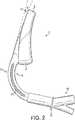
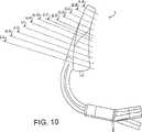
Unter Bezugnahme zunächst auf den Luftwegschlauch
Unter Bezugnahme nun auf
Ein weiteres Merkmal des Luftweges
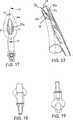
Das proximale Ende des Luftwegschlauchs
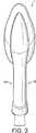
Bei Betrachtung nun der Maske
Die Rückplatte
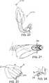
Unter Bezugnahme nun auf
Die dorsale Fläche
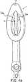
Bei Betrachtung von der ventralen Seite sind die integral geformten Strukturen der Rückplatte
Die Wände
Unter ausführlicherer Bezugnahme nun auf den Drainagetubus
Unter Bezugnahme nun insbesondere auf
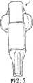
Wie in
Der zweite Teil der Maske
In der zusammengebauten Vorrichtung
Der Luftwegschlauch
Die Manschette
Wie erkennbar ist, ist der Luftweg der Vorrichtung
In Gebrauch wird die luftentleerte Vorrichtung
Unter Bezugnahme nun auf die Merkmale der geformten Rückplatte
Ferner unterstützt bei der Rückplatte der Erfindung die Kombination aus dem zentral angeordneten Drainagetubus
ZITATE ENTHALTEN IN DER BESCHREIBUNG QUOTES INCLUDE IN THE DESCRIPTION
Diese Liste der vom Anmelder aufgeführten Dokumente wurde automatisiert erzeugt und ist ausschließlich zur besseren Information des Lesers aufgenommen. Die Liste ist nicht Bestandteil der deutschen Patent- bzw. Gebrauchsmusteranmeldung. Das DPMA übernimmt keinerlei Haftung für etwaige Fehler oder Auslassungen.This list of the documents listed by the applicant has been generated automatically and is included solely for the better information of the reader. The list is not part of the German patent or utility model application. The DPMA assumes no liability for any errors or omissions.
Zitierte PatentliteraturCited patent literature
- US 4509514[0002, 0006]US 4509514[0002, 0006]
- US 5303697[0005, 0006]US 5303697[0005, 0006]
- US 6079409[0005]US 6079409[0005]
- US 5249571[0006]US 5249571[0006]
- US 5282464[0006]US 5282464[0006]
- US 5297547[0006]US 5297547[0006]
- UK 2205499[0006]UK 2205499[0006]
- US 4995388[0006]US 4995388[0006]
- US 5241956[0006]US 5241956[0006]
- US 5355879[0006]US 5355879[0006]
Claims (13)
Translated fromGermanApplications Claiming Priority (2)
| Application Number | Priority Date | Filing Date | Title |
|---|---|---|---|
| GB0510951 | 2005-05-27 | ||
| GBGB0510951.7AGB0510951D0 (en) | 2005-05-27 | 2005-05-27 | Laryngeal mask airway device |
Publications (1)
| Publication Number | Publication Date |
|---|---|
| DE202006021004U1true DE202006021004U1 (en) | 2011-11-30 |
Family
ID=34834809
Family Applications (2)
| Application Number | Title | Priority Date | Filing Date |
|---|---|---|---|
| DE202006021004UExpired - LifetimeDE202006021004U1 (en) | 2005-05-27 | 2006-05-24 | Device for laryngeal mask |
| DE202006021001UExpired - LifetimeDE202006021001U1 (en) | 2005-05-27 | 2006-05-24 | Device for laryngeal mask |
Family Applications After (1)
| Application Number | Title | Priority Date | Filing Date |
|---|---|---|---|
| DE202006021001UExpired - LifetimeDE202006021001U1 (en) | 2005-05-27 | 2006-05-24 | Device for laryngeal mask |
Country Status (18)
| Country | Link |
|---|---|
| US (9) | US20080308109A1 (en) |
| EP (5) | EP1885422B1 (en) |
| JP (7) | JP4828598B2 (en) |
| KR (4) | KR20080031211A (en) |
| CN (6) | CN102688548B (en) |
| AR (4) | AR057038A1 (en) |
| AU (4) | AU2006250999B2 (en) |
| BR (4) | BRPI0610083B1 (en) |
| CA (4) | CA2609472C (en) |
| DE (2) | DE202006021004U1 (en) |
| ES (2) | ES2592912T3 (en) |
| GB (1) | GB0510951D0 (en) |
| IL (4) | IL187571A0 (en) |
| MX (4) | MX2007014905A (en) |
| RU (4) | RU2412725C2 (en) |
| TW (4) | TW200716214A (en) |
| WO (4) | WO2006125987A1 (en) |
| ZA (4) | ZA200710525B (en) |
Families Citing this family (76)
| Publication number | Priority date | Publication date | Assignee | Title |
|---|---|---|---|---|
| US5915379A (en) | 1997-03-14 | 1999-06-29 | Nellcor Puritan Bennett Incorporated | Graphic user interface for a patient ventilator |
| WO2005016427A2 (en) | 2003-08-14 | 2005-02-24 | Muhammed Aslam Nasir | Improved airway device |
| GB0218868D0 (en) | 2002-08-14 | 2002-09-25 | Nasir Muhammed A | Improved airway management device |
| GB0510951D0 (en) | 2005-05-27 | 2005-07-06 | Laryngeal Mask Company The Ltd | Laryngeal mask airway device |
| US9084912B2 (en)* | 2005-10-19 | 2015-07-21 | Performance Health Systems, Llc | Systems and methods for administering an exercise program |
| US8021310B2 (en) | 2006-04-21 | 2011-09-20 | Nellcor Puritan Bennett Llc | Work of breathing display for a ventilation system |
| US7784461B2 (en) | 2006-09-26 | 2010-08-31 | Nellcor Puritan Bennett Llc | Three-dimensional waveform display for a breathing assistance system |
| GB2454199A (en)* | 2007-10-30 | 2009-05-06 | Laryngeal Mask Co Ltd | Laryngeal mask with tape tab |
| GB0821291D0 (en)* | 2008-11-21 | 2008-12-31 | Nasir Muhammed A | Improved airway device |
| USD618788S1 (en)* | 2008-11-27 | 2010-06-29 | Deltona Innovations Ag | Laryngeal mask |
| CH699987A1 (en)* | 2008-11-27 | 2010-05-31 | Deltona Innovations Ag | Laryngeal mask with a nozzle. |
| CH699986A1 (en)* | 2008-11-27 | 2010-05-31 | Deltona Innovations Ag | Laryngeal Mask with Oesophagealdurchgang. |
| GB0903654D0 (en) | 2009-03-03 | 2009-04-15 | Laryngeal Mask Company The Ltd | Artificial airway device |
| WO2011003135A1 (en)* | 2009-07-06 | 2011-01-13 | Ultimate Medical Pty. Ltd. | Artificial airway |
| WO2011017756A1 (en) | 2009-08-13 | 2011-02-17 | Ultimate Medical Pty. Ltd. | Pressure indicator |
| US8924878B2 (en) | 2009-12-04 | 2014-12-30 | Covidien Lp | Display and access to settings on a ventilator graphical user interface |
| US8335992B2 (en) | 2009-12-04 | 2012-12-18 | Nellcor Puritan Bennett Llc | Visual indication of settings changes on a ventilator graphical user interface |
| US9119925B2 (en) | 2009-12-04 | 2015-09-01 | Covidien Lp | Quick initiation of respiratory support via a ventilator user interface |
| US9262588B2 (en) | 2009-12-18 | 2016-02-16 | Covidien Lp | Display of respiratory data graphs on a ventilator graphical user interface |
| US8499252B2 (en) | 2009-12-18 | 2013-07-30 | Covidien Lp | Display of respiratory data graphs on a ventilator graphical user interface |
| WO2011106754A1 (en) | 2010-02-27 | 2011-09-01 | King Systems Corporation | Laryngeal tube |
| GB201010647D0 (en) | 2010-06-24 | 2010-08-11 | Docsinnovent Ltd | Stopper device |
| GB201016562D0 (en)* | 2010-10-01 | 2010-11-17 | Laryngeal Mask Company The Ltd | Artificial airway device |
| EP2627387B1 (en)* | 2010-10-15 | 2018-08-15 | Teleflex Life Sciences Unlimited Company | Artificial airway device |
| CA3016781C (en) | 2010-11-12 | 2020-09-15 | Wolfe Tory Medical, Inc. | Atomizer for nasal therapy |
| DK201001052A (en)* | 2010-11-19 | 2011-11-10 | Ambu As | A tracheal intubation guide |
| JP6242687B2 (en) | 2011-02-02 | 2017-12-06 | ウメダス、リミテッドUmedaes Limited | Improved artificial airway |
| USD693920S1 (en) | 2011-06-08 | 2013-11-19 | Intersurgical Ag | Airway device |
| USD688787S1 (en)* | 2011-06-08 | 2013-08-27 | Intersurgical Ag | Airway device cap and strap holder |
| CA144804S (en)* | 2011-09-07 | 2012-12-20 | Laryngeal Mask Co Ltd | Laryngeal mask |
| USD712244S1 (en) | 2011-09-23 | 2014-09-02 | Intersurgical Ag | Medical device package |
| USD716937S1 (en)* | 2011-10-18 | 2014-11-04 | The Laryngeal Mask Company Limited | Laryngeal mask airway device |
| GB201120628D0 (en) | 2011-11-30 | 2012-01-11 | Laryngeal Mask Company The Ltd | Endoscopy device |
| USD761952S1 (en) | 2012-07-27 | 2016-07-19 | Docsinnovent Limited | Airway device |
| GB201201438D0 (en)* | 2012-01-27 | 2012-03-14 | Docsinnovent Ltd | Improved stopper device |
| US10362967B2 (en) | 2012-07-09 | 2019-07-30 | Covidien Lp | Systems and methods for missed breath detection and indication |
| CN102908704A (en)* | 2012-10-31 | 2013-02-06 | 南昌贝欧特医疗设备有限公司 | Laryngeal mask |
| GB201314631D0 (en) | 2013-08-15 | 2013-10-02 | Teleflex Life Sciences | Endoscopy device |
| CN103432670B (en)* | 2013-09-10 | 2015-06-10 | 广州维力医疗器械股份有限公司 | Laryngeal mask breather tube device and manufacturing method thereof |
| KR101508131B1 (en)* | 2013-09-26 | 2015-04-07 | 정민호 | Airway device |
| GB201317596D0 (en)* | 2013-10-04 | 2013-11-20 | Teleflex Life Sciences | Biteblock |
| FR3014258B1 (en) | 2013-12-02 | 2017-02-17 | Schneider Electric Ind Sas | FIRE PROTECTION DEVICE OF A STARTER-CONTROLLER DEVICE OF AN ELECTRICAL INSTALLATION |
| GB2546167B (en) | 2013-12-17 | 2018-02-28 | Aslam Nasir Muhammed | Intubating Airway Device |
| GB2522403B (en)* | 2013-12-17 | 2017-09-13 | Aslam Nasir Muhammed | Airway device with flexible divider |
| DK177742B1 (en)* | 2014-01-24 | 2014-05-19 | Ambu As | A laryngeal mask with a bite absorbing connector |
| JP6378886B2 (en)* | 2014-01-31 | 2018-08-22 | 大研医器株式会社 | Laryngeal mask |
| SG2014011720A (en)* | 2014-02-10 | 2015-09-29 | Craig Wight Ronald | An airway management device and method of manufacture |
| CA158881S (en)* | 2014-03-28 | 2015-05-04 | Teleflex Life Sciences | Laryngeal mask |
| US9950129B2 (en) | 2014-10-27 | 2018-04-24 | Covidien Lp | Ventilation triggering using change-point detection |
| US9283342B1 (en)* | 2015-03-04 | 2016-03-15 | Glenn P. Gardner | Endotracheal tube insertion device |
| USD842456S1 (en) | 2015-12-15 | 2019-03-05 | Intersurgical Ag | Airway device |
| USD1051359S1 (en) | 2015-06-15 | 2024-11-12 | Intersurgical Ag | Airway device |
| CN105214188B (en)* | 2015-11-09 | 2017-07-28 | 汤立 | Laryngeal mask with multiple tube cavities |
| AU2017282981A1 (en) | 2016-03-31 | 2018-10-18 | Teleflex Life Sciences Llc | Fixation device for a laryngeal mask |
| KR101789171B1 (en) | 2016-07-13 | 2017-10-25 | 한양대학교 산학협력단 | Apparatus for free airway and guiding intubation tube |
| US10821248B2 (en)* | 2017-02-06 | 2020-11-03 | David James Durkin | Courier airway device |
| AU201714823S (en) | 2017-02-27 | 2017-10-12 | Teleflex Life Sciences Unlimited Co | Laryngeal mask airway device |
| CN107137807B (en)* | 2017-05-02 | 2020-06-09 | 浙江简成医疗科技有限公司 | Laryngeal mask |
| US10314995B2 (en) | 2017-08-17 | 2019-06-11 | Yang Sun | Endotracheal intubation and supraglottic airway device |
| CN107737394A (en)* | 2017-11-15 | 2018-02-27 | 方峥评 | A kind of Puffer-type rinses laryngeal mask |
| US10173022B1 (en) | 2017-11-29 | 2019-01-08 | Airway Medix S.A. | Laryngeal mask cuff |
| US10369311B2 (en) | 2017-11-29 | 2019-08-06 | Airway Medix S.A. | Laryngeal mask cuff |
| US10744287B2 (en) | 2017-11-29 | 2020-08-18 | Airway Medix S.A. | Laryngeal mask cuffs |
| GB201720733D0 (en) | 2017-12-13 | 2018-01-24 | Ashkal Development Ltd | Airway device |
| WO2019155481A1 (en)* | 2018-02-07 | 2019-08-15 | Ananthanarayanan Kalyanaraman | Supraglottic airway device with a dynamic cuff with superior ventilating capability |
| JP1649726S (en) | 2019-01-18 | 2020-01-14 | ||
| JP2022522633A (en) | 2019-02-08 | 2022-04-20 | クレイグ ワイト,ロナルド | Airway management device and manufacturing method of objects |
| EP3698836A1 (en)* | 2019-02-25 | 2020-08-26 | Visual Oxy, S.L. | Laryngeal mask |
| CN111298257A (en)* | 2020-03-25 | 2020-06-19 | 苏州大学附属第二医院 | A three-head multifunctional laryngeal mask for airway surgery |
| USD1025348S1 (en) | 2020-04-16 | 2024-04-30 | Intersurgical Ag | Airway device |
| CN111660570B (en)* | 2020-05-07 | 2021-08-31 | 江门市康馨医疗器械有限公司 | Laryngeal mask, hot-melt welding method and hot-melt welding equipment |
| US11672934B2 (en) | 2020-05-12 | 2023-06-13 | Covidien Lp | Remote ventilator adjustment |
| US20230181852A1 (en)* | 2020-05-18 | 2023-06-15 | Pedro Luis BRAVO GARCÍA | Endotracheal device for mechanical ventilation of a patient |
| US20230211101A1 (en) | 2020-06-05 | 2023-07-06 | Oron Zachar | Laryngeal mask airway devices |
| CN112007248A (en)* | 2020-08-05 | 2020-12-01 | 朱燕 | Visual laryngeal mask auxiliary mounting system for department of pediatrics |
| KR102559960B1 (en) | 2022-12-26 | 2023-07-25 | 주형준 | Laryngeal mask for tracheal intubation |
Citations (10)
| Publication number | Priority date | Publication date | Assignee | Title |
|---|---|---|---|---|
| US4509514A (en) | 1981-12-16 | 1985-04-09 | Brain Archibald Ian Jeremy | Artificial airway device |
| GB2205499A (en) | 1987-06-05 | 1988-12-14 | Archibald Ian Jeremy Brain | Artificial airway device |
| US4995388A (en) | 1989-03-22 | 1991-02-26 | Brain Archibald I | Artificial airway device |
| US5241956A (en) | 1992-05-21 | 1993-09-07 | Brain Archibald Ian Jeremy | Laryngeal mask airway with concentric drainage of oesophagus discharge |
| US5249571A (en) | 1992-05-21 | 1993-10-05 | Brain Archibald Ian Jeremy | Laryngeal clamp airway |
| US5282464A (en) | 1992-07-21 | 1994-02-01 | Brain Archibald Ian Jeremy | Combined laryngeal mask and reflectance oximeter |
| US5297547A (en) | 1992-07-30 | 1994-03-29 | Brain Archibald Ian Jeremy | Laryngeal mask construction |
| US5303697A (en) | 1991-02-11 | 1994-04-19 | Brain Archibald Ian Jeremy | Artificial airway device |
| US5355879A (en) | 1992-09-28 | 1994-10-18 | Brain Archibald Ian Jeremy | Laryngeal-mask construction |
| US6079409A (en) | 1997-07-25 | 2000-06-27 | Brain; Archibald Ian Jeremy | Intubating laryngeal mask |
Family Cites Families (201)
| Publication number | Priority date | Publication date | Assignee | Title |
|---|---|---|---|---|
| US2099127A (en) | 1936-12-30 | 1937-11-16 | Foregger Co Inc | Pharyngeal bulb gasway |
| US2839788A (en)* | 1953-04-24 | 1958-06-24 | Dembiak Matthew | Method of making hollow plastic or rubber articles |
| US2862498A (en) | 1957-06-14 | 1958-12-02 | Don J Weekes | Endotracheal tube |
| US3529596A (en) | 1968-04-03 | 1970-09-22 | Charles G Garner | Automatic intermittent tracheotomy tube cuff inflator-deflator |
| US3554673A (en) | 1969-01-31 | 1971-01-12 | Sage Instr Inc | Syringe pump |
| US3683908A (en) | 1969-10-20 | 1972-08-15 | Tantrimudalige Anthony Don Mic | Apparatus for sealing the oesophagus and providing artificial respiration |
| US3774616A (en) | 1972-02-01 | 1973-11-27 | Perry Plastics Inc | Endotracheal tube holder and airway |
| US3794036A (en) | 1972-08-02 | 1974-02-26 | R Carroll | Pressure regulated inflatable cuff for an endotracheal or tracheostomy tube |
| US4104357A (en)* | 1973-01-10 | 1978-08-01 | Monster Molding, Inc. | Method of rotational molding about plural axes at low rotational speeds |
| US3931822A (en) | 1974-02-26 | 1976-01-13 | Marici Frank N | Automatic alternating cuff endo tracheal tube inflator |
| FR2298147A1 (en)* | 1975-01-17 | 1976-08-13 | Ucc Union Chimique Cont | DEVICE GIVING THE ALARM IN CASE OF DISCONNECTION OF A HOSE, IN PARTICULAR OF A RESPIRATOR |
| US4116201A (en) | 1976-12-20 | 1978-09-26 | The Kendall Company | Catheter with inflation control device |
| US4134407A (en)* | 1977-03-25 | 1979-01-16 | Elam James O | External pressure-volume monitor for endotracheal cuff |
| US4159722A (en)* | 1977-03-28 | 1979-07-03 | Sherwood Medical Industries, Inc. | Pressure regulator for endotracheal tube cuff or the like |
| US4178940A (en) | 1977-06-24 | 1979-12-18 | Au Anthony S | Pressure control systems |
| US4178938A (en) | 1977-06-24 | 1979-12-18 | Au Anthony S | Pressure control systems |
| US4166467A (en) | 1977-08-08 | 1979-09-04 | Metatech Corporation | Bite block for endotracheal tube |
| US4351330A (en) | 1978-01-30 | 1982-09-28 | Scarberry Eugene N | Emergency internal defibrillation |
| US4231365A (en) | 1978-01-30 | 1980-11-04 | Scarberry Eugene N | Emergency resuscitation apparatus |
| US4285340A (en)* | 1979-03-16 | 1981-08-25 | Gezari Walter A | Apparatus for controlling the pressure in a tracheal cuff |
| US4256099A (en)* | 1979-03-21 | 1981-03-17 | Dryden Gale E | Two-tube resuscitation system |
| JPS5667383A (en)* | 1979-11-08 | 1981-06-06 | Mitsui Petrochem Ind Ltd | Thixotropic agent |
| US4446864A (en)* | 1980-07-10 | 1984-05-08 | Watson Robert L | Emergency ventilation tube |
| US4425911A (en) | 1981-07-27 | 1984-01-17 | Raymond Luomanen | Bite-block |
| US4531330A (en) | 1982-02-01 | 1985-07-30 | Phillips William E | Bed/shelter unit |
| US4471775A (en) | 1982-09-07 | 1984-09-18 | Clair Michael W | Endotracheal tube cuff synchronizing system |
| US4501273A (en)* | 1982-09-30 | 1985-02-26 | Mcginnis Gerald E | Endotracheal tube with pressure controlled inflatable cuff |
| US4526196A (en)* | 1983-01-26 | 1985-07-02 | Nayan S. Shah | Gas pressure measuring and regulating device and method |
| US4583917A (en)* | 1983-06-17 | 1986-04-22 | Shah Nayan S | Pressure regulating and monitoring device |
| DE3327342A1 (en) | 1983-07-29 | 1985-02-07 | Peter 7800 Freiburg Pedersen | DEVICE FOR DETECTING AND EVALUATING THE PRESSURE IN THE BALLOON CUFF OF A CLOSED TRACHEAL TUBE |
| US4553540A (en) | 1983-08-16 | 1985-11-19 | Straith Richard E | Airway |
| US4689041A (en)* | 1984-01-20 | 1987-08-25 | Eliot Corday | Retrograde delivery of pharmacologic and diagnostic agents via venous circulation |
| JPS628766A (en) | 1985-07-03 | 1987-01-16 | 鳥取大学長 | Cuff pressure controller of gas insert tube with cuff |
| US4793327A (en) | 1986-01-21 | 1988-12-27 | Frankel Alfred R | Device for opening a patient's airway during automatic intubation of the trachea |
| JPS62186872A (en)* | 1986-02-14 | 1987-08-15 | 鳥取大学長 | Respiration pressure superposing type cuff pressure adjusting apparatus |
| US4700700A (en) | 1986-09-15 | 1987-10-20 | The Cleveland Clinic Foundation | Endotracheal tube |
| US4832020A (en) | 1987-03-24 | 1989-05-23 | Augustine Scott D | Tracheal intubation guide |
| US5203320A (en)* | 1987-03-24 | 1993-04-20 | Augustine Medical, Inc. | Tracheal intubation guide |
| US5042469A (en)* | 1987-03-24 | 1991-08-27 | Augustine Medical, Inc. | Tracheal intubation guide |
| US4798597A (en)* | 1987-04-29 | 1989-01-17 | Sherwood Medical Co | Flexible composite intubation tube |
| US4924862A (en)* | 1987-08-19 | 1990-05-15 | Gary Levinson | Pressure controller and leak detector for tracheal tube cuff |
| US4850349A (en)* | 1987-12-04 | 1989-07-25 | Farahany Amir H | Endotracheal tube sealing cuff system |
| US4872483A (en) | 1987-12-31 | 1989-10-10 | International Medical Products, Inc. | Conveniently hand held self-contained electronic manometer and pressure modulating device |
| US4856510A (en)* | 1988-04-06 | 1989-08-15 | Kowalewski Ryszard J | Tracheal tube inflator |
| US5067496A (en) | 1988-04-07 | 1991-11-26 | Shiley Incorporated | Tracheostomy tube |
| US4972963A (en)* | 1988-10-31 | 1990-11-27 | Guarriello Henry J | Blow molded article with reverse lip |
| US4953547A (en) | 1989-01-26 | 1990-09-04 | Poole Jr Samuel E | Drug administering endotracheal respiration systems |
| US5169379A (en) | 1989-06-14 | 1992-12-08 | L-Vad Technology | In-series ventricular assist system and method of controlling same |
| US4981470A (en)* | 1989-06-21 | 1991-01-01 | Synectics Medical, Inc. | Intraesophageal catheter with pH sensor |
| JPH0339169A (en)* | 1989-07-06 | 1991-02-20 | B Hazaado Patrick | Percutaneous tracheotomic tube |
| US5042476A (en)* | 1989-08-10 | 1991-08-27 | Smith Charles A | Endotracheal tube protection arrangement |
| EP0490979B1 (en) | 1989-09-08 | 1996-11-13 | Boston Scientific Corporation | Physiologic low stress angioplasty |
| US5038766A (en) | 1989-11-08 | 1991-08-13 | Parker Jeffrey D | Blind orolaryngeal and oroesophageal guiding and aiming device |
| US5174283A (en) | 1989-11-08 | 1992-12-29 | Parker Jeffrey D | Blind orolaryngeal and oroesophageal guiding and aiming device |
| GB9003857D0 (en) | 1990-02-21 | 1990-04-18 | Smiths Industries Plc | Medico-surgical tube assemblies |
| GB9026403D0 (en)* | 1990-12-05 | 1991-01-23 | Smiths Industries Plc | Pressure monitors |
| US5339808A (en) | 1991-04-02 | 1994-08-23 | Don Michael T Anthony | Endotracheal-esophageal intubation devices |
| US5235973A (en)* | 1991-05-15 | 1993-08-17 | Gary Levinson | Tracheal tube cuff inflation control and monitoring system |
| US5795325A (en) | 1991-07-16 | 1998-08-18 | Heartport, Inc. | Methods and apparatus for anchoring an occluding member |
| GB9119703D0 (en)* | 1991-09-14 | 1991-10-30 | Dingley John | Medico-surgical device |
| US5113875A (en) | 1991-09-24 | 1992-05-19 | Bennett Trevor S | Inflatable leg-supporting bolster |
| US5241325A (en)* | 1991-10-31 | 1993-08-31 | Hewlett-Packard Company | Print cartridge cam actuator linkage |
| GB9204754D0 (en)* | 1992-03-05 | 1992-04-15 | Brain Archibald Ian Jeremy | Mould for manufacture of a laryngeal mask |
| MX9301163A (en)* | 1992-03-05 | 1994-07-29 | Brain Archibald Ian Jeremy | LARINGEA MASK AND METHOD FOR ITS MANUFACTURE. |
| US5273537A (en) | 1992-03-06 | 1993-12-28 | Scimed Life Systems, Inc. | Power-assisted inflation apparatus |
| US5421325A (en)* | 1992-04-30 | 1995-06-06 | Cinberg; James Z. | Endotracheal tube assembly and related method |
| US5546936A (en)* | 1992-05-19 | 1996-08-20 | Mallinckrodt Medical, Inc. | Tracheal tube with reinforced flexible segment |
| DE4222220A1 (en) | 1992-07-07 | 1994-01-13 | Deutsche Aerospace | Procedure for measuring and regulating the pressure in the sealing sleeve of a tracheal tube |
| EP0580385B1 (en) | 1992-07-21 | 1996-05-08 | Archibald Ian Jeremy Dr. Brain | Laryngeal mask incorporating a reflectance oximeter |
| ZA927931B (en)* | 1992-08-24 | 1994-04-14 | Donald Munro Miller | Breathing apparatus |
| US5400771A (en) | 1993-01-21 | 1995-03-28 | Pirak; Leon | Endotracheal intubation assembly and related method |
| US5331967A (en) | 1993-02-05 | 1994-07-26 | Playa De Los Vivos S.A. | Tracheal intubation monitoring apparatus and method |
| US5546935A (en) | 1993-03-09 | 1996-08-20 | Medamicus, Inc. | Endotracheal tube mounted pressure transducer |
| GB9312131D0 (en)* | 1993-06-11 | 1993-07-28 | Blatchford & Sons Ltd | Prosthesis control system |
| FR2709251B1 (en) | 1993-08-26 | 1995-11-10 | Georges Boussignac | Breathing assistance tube. |
| US5443063A (en) | 1993-08-31 | 1995-08-22 | The Johns Hopkins University | Cuffed oro-pharyngeal airway |
| US5692498A (en) | 1993-11-09 | 1997-12-02 | Cprx, Inc. | CPR device having valve for increasing the duration and magnitude of negative intrathoracic pressures |
| US5551420A (en) | 1993-11-09 | 1996-09-03 | Cprx, Inc. | CPR device and method with structure for increasing the duration and magnitude of negative intrathoracic pressures |
| US6062219A (en) | 1993-11-09 | 2000-05-16 | Cprx Llc | Apparatus and methods for assisting cardiopulmonary resuscitation |
| US5459700A (en) | 1993-11-22 | 1995-10-17 | Advanced Cardiovascular Systems, Inc. | Manual timer control for inflation device |
| US5599301A (en)* | 1993-11-22 | 1997-02-04 | Advanced Cardiovascular Systems, Inc. | Motor control system for an automatic catheter inflation system |
| US5554673A (en) | 1993-11-29 | 1996-09-10 | Polygenex International, Inc. | Dip molded polyurethane film compositions |
| GB2285765B (en)* | 1994-01-12 | 1997-10-29 | Archibald Ian Jeremy Brain | Forming tool for use with a laryngeal mask |
| US5499625A (en) | 1994-01-27 | 1996-03-19 | The Kendall Company | Esophageal-tracheal double lumen airway |
| US5529582A (en)* | 1994-02-01 | 1996-06-25 | Fukuhara; Tomio | Apparatus for inserting laryngeal mask |
| US5582167A (en) | 1994-03-02 | 1996-12-10 | Thomas Jefferson University | Methods and apparatus for reducing tracheal infection using subglottic irrigation, drainage and servoregulation of endotracheal tube cuff pressure |
| JP3782123B2 (en) | 1994-05-31 | 2006-06-07 | 住友ベークライト株式会社 | Pharyngeal airway |
| GB9411215D0 (en)* | 1994-06-04 | 1994-07-27 | Brain Archibald Ian Jeremy | A fibreoptic intubating laryngeal mask airway |
| SE503155C2 (en) | 1994-07-28 | 1996-04-01 | Comasec International Sa | Methods and apparatus for functional control of breathing apparatus |
| US5569219A (en) | 1994-09-13 | 1996-10-29 | Hakki; A-Hamid | Collapsible catheter |
| GB9422224D0 (en) | 1994-11-03 | 1994-12-21 | Brain Archibald Ian Jeremy | A laryngeal mask airway device modified to detect and/or stimulate mescle or nerve activity |
| DE4447186A1 (en) | 1994-12-30 | 1996-07-11 | Johann Dr Med Wittenbeck | Larynx mask for fibre optic endotracheal intubation with simultaneous artificial respiration |
| US5577693A (en) | 1995-01-11 | 1996-11-26 | Children's Medical Center Corporation | Anesthesia circuit stand |
| US5477851A (en) | 1995-01-26 | 1995-12-26 | Callaghan; Eric B. | Laryngeal mask assembly and method for removing same |
| US5513627A (en) | 1995-01-27 | 1996-05-07 | Flam; Gary H. | Esophageal tracheal intubator airway |
| GB9504657D0 (en) | 1995-03-08 | 1995-04-26 | Neil Michael J O | An improved artificial airway device |
| GB9505134D0 (en)* | 1995-03-14 | 1995-05-03 | Smiths Industries Plc | Laryngeal mask airways |
| GB2298797B (en) | 1995-03-14 | 1998-12-09 | Smiths Industries Plc | Laryngeal mask airways |
| GB9505399D0 (en)* | 1995-03-17 | 1995-05-03 | Smiths Industries Plc | Medico-surgical devices |
| GB9513860D0 (en)* | 1995-07-07 | 1995-09-06 | Smiths Industries Plc | Securing devices |
| AUPN417395A0 (en) | 1995-07-14 | 1995-08-10 | Techbase Pty. Ltd. | An improved spacer |
| AUPN538495A0 (en) | 1995-09-12 | 1995-10-05 | Esnouf, Philip Stuart | Disposable oxygenating device |
| MY115052A (en) | 1995-10-03 | 2003-03-31 | Archibald Ian Jeremy Brain | Laryngeal mask airway incorporating an epiglottic elevating mechanism |
| MY138519A (en)* | 1995-10-03 | 2009-06-30 | Indian Ocean Medical Inc | Artificial airway device |
| US5794617A (en) | 1995-10-19 | 1998-08-18 | Louis M. Gerson Co., Inc. | Face mask and retainer |
| US5791341A (en)* | 1995-12-19 | 1998-08-11 | Bullard; James Roger | Oropharyngeal stent with laryngeal aditus shield and nasal airway with laryngeal aditus shield |
| US5832916A (en) | 1996-02-20 | 1998-11-10 | Interspiro Ab | Method and system for checking the operability of electrical-based components in a breathing equipment |
| US5694929A (en) | 1996-02-26 | 1997-12-09 | Christopher; Kent L. | Method and apparatus for ventilation/oxygenation during guided insertion of an endotracheal tube |
| US5878745A (en)* | 1996-03-01 | 1999-03-09 | Brain; Archibald I.J. | Gastro-laryngeal mask |
| US5626151A (en)* | 1996-03-07 | 1997-05-06 | The United States Of America As Represented By The Secretary Of The Army | Transportable life support system |
| GB9606012D0 (en) | 1996-03-22 | 1996-05-22 | Brain Archibald Ian Jeremy | Laryngeal mask with gastric-drainage feature |
| RU2116044C1 (en)* | 1996-04-02 | 1998-07-27 | Геннадий Борисович Яцевич | Panoramic light fiberscope |
| US5623921A (en)* | 1996-04-10 | 1997-04-29 | Kinsinger; J. William | Laryngeal mask airway and method for its use |
| IT240586Y1 (en)* | 1996-04-11 | 2001-04-02 | Mallinckrodt Medical S P A | BRONCHO ASPIRATION STRUCTURE FOR THE REMOVAL OF EXECUTIONS FROM TRACHEAL TUBES AND THE UPPER ROUTE OF THE ROUTES |
| US5682880A (en) | 1996-07-26 | 1997-11-04 | Brain; Archibald Ian Jeremy | Laryngeal-mask airway with guide element, stiffener, and fiberoptic access |
| US5738094A (en) | 1996-08-30 | 1998-04-14 | Hoftman; Moshe | Anesthesia/respirator mask with reduced nasal section enclosure and inflatable cuff |
| GB9619432D0 (en)* | 1996-09-18 | 1996-10-30 | Smiths Industries Plc | Laryngeal mask assemblies |
| GB2317342B (en) | 1996-09-18 | 2000-03-29 | Smiths Industries Plc | Laryngeal mask assemblies |
| GB2317830B (en) | 1996-10-03 | 2000-03-29 | Smiths Industries Plc | Laryngeal mask airways and their manufacture |
| GB9620609D0 (en) | 1996-10-03 | 1996-11-20 | Smiths Industries Plc | Laryngeal mask airways and their manufacture |
| US6427686B2 (en) | 1996-10-16 | 2002-08-06 | Augustine Medical, Inc. | Airway device with provision for coupling to an introducer |
| GB2318297B (en) | 1996-10-16 | 2000-04-12 | Smiths Industries Plc | A tracheal shield assembly |
| US6070581A (en) | 1996-10-16 | 2000-06-06 | Augustine Medical, Inc. | Laryngeal airway device |
| US7051096B1 (en)* | 1999-09-02 | 2006-05-23 | Citicorp Development Center, Inc. | System and method for providing global self-service financial transaction terminals with worldwide web content, centralized management, and local and remote administration |
| GB9622880D0 (en) | 1996-11-02 | 1997-01-08 | Smiths Industries Plc | Laryngeal mask airways and thier manufacture |
| GB2318735B (en) | 1996-11-02 | 2000-04-19 | Smiths Industries Plc | Laryngeal mask airways and their manufacture |
| US5778872A (en)* | 1996-11-18 | 1998-07-14 | Medlis, Inc. | Artificial ventilation system and methods of controlling carbon dioxide rebreathing |
| US6003511A (en) | 1996-11-18 | 1999-12-21 | Medlis Corp. | Respiratory circuit terminal for a unilimb respiratory device |
| GB2319478B (en) | 1996-11-19 | 2000-04-19 | Smiths Industries Plc | Laryngeal mask airways and their manufacture |
| GB9624029D0 (en)* | 1996-11-19 | 1997-01-08 | Smiths Industries Ltd | Laryngeal mask airways and their manufacture |
| US5856510A (en) | 1996-12-16 | 1999-01-05 | Allelix Biopharmaceuticals Inc. | 5-alkenyl and 5-alkynyl indole compounds |
| US5921239A (en) | 1997-01-07 | 1999-07-13 | Sunrise Medical Hhg Inc. | Face mask for patient breathing |
| GB9702337D0 (en) | 1997-02-05 | 1997-03-26 | Smiths Industries Plc | Laryngeal mask airways and their manufacture |
| US5743254A (en)* | 1997-03-18 | 1998-04-28 | Parker Medical Limited Partnership | Orotracheal intubation guide |
| GB9705586D0 (en) | 1997-03-18 | 1997-05-07 | Smiths Industries Plc | Laryngeal mask assemblies |
| GB9705537D0 (en)* | 1997-03-18 | 1997-05-07 | Smiths Industries Plc | Laryngeal mask assemblies |
| GB9705585D0 (en) | 1997-03-18 | 1997-05-07 | Smiths Industries Plc | Laryngeal mask assemlies |
| GB2323289B (en) | 1997-03-18 | 2001-02-14 | Smiths Industries Plc | Laryngeal mask assemblies |
| US5937860A (en) | 1997-04-10 | 1999-08-17 | Cook; Daniel J. | Laryngeal mask |
| US8631796B2 (en)* | 1997-04-10 | 2014-01-21 | Cookgas, L.L.C. | Laryngeal mask |
| GB9708568D0 (en)* | 1997-04-29 | 1997-06-18 | Smiths Industries Ltd | Cuffed medico-surgical tubes |
| US6131571A (en) | 1997-04-30 | 2000-10-17 | University Of Florida | Ventilation apparatus and anesthesia delivery system |
| US5988167A (en) | 1997-05-02 | 1999-11-23 | Kamen; Jack M. | Foam cuff for laryngeal mask airway |
| GB2324737A (en) | 1997-05-03 | 1998-11-04 | Smiths Industries Plc | Laryngeal mask assembly |
| GB9709297D0 (en) | 1997-05-03 | 1997-06-25 | Smiths Industries Plc | Laryngeal mask assemblies |
| GB9710645D0 (en) | 1997-05-22 | 1997-07-16 | Smiths Industries Plc | Cuffed tube assemblies |
| JPH10323391A (en) | 1997-05-23 | 1998-12-08 | Aoki Shigeru | Stable laryngeal mask |
| US5850832A (en) | 1997-06-23 | 1998-12-22 | Chu; Kyo Y. | Laryngeal mask airway insertion guide |
| US5957133A (en) | 1997-07-21 | 1999-09-28 | Hart; William T. | Oral appliance with negative air supply for reducing sleep apnea and snoring |
| GB9716287D0 (en) | 1997-08-02 | 1997-10-08 | Nimmo Garry H | Apparatus for shaping a laryngeal mask |
| US6213120B1 (en)* | 1997-08-21 | 2001-04-10 | Instrumentarium Corporation | Device and method for determining gas volume and volumetric changes in a ventilator |
| US6474332B2 (en) | 1997-10-03 | 2002-11-05 | Wisconsin Medical Incorporated | Bite block |
| GB9721840D0 (en) | 1997-10-16 | 1997-12-17 | Smiths Industries Plc | Laryngeal mask assemblies |
| US5924862A (en)* | 1997-10-28 | 1999-07-20 | White; Dennis J | Method and apparatus to verify dental model accuracy |
| GB9725389D0 (en) | 1997-12-02 | 1998-01-28 | Smiths Industries Plc | Laryngeal mask assemblies |
| US6003510A (en) | 1997-12-04 | 1999-12-21 | Anunta; Boonchuay | Hand tool for introducing a laryngeal mask |
| US5976075A (en) | 1997-12-15 | 1999-11-02 | University Of Massachusetts | Endoscope deployment apparatus |
| US5855203A (en) | 1997-12-19 | 1999-01-05 | Matter; Jean-Paul | Respiratory circuit with in vivo sterilization |
| GB9727367D0 (en) | 1997-12-24 | 1998-02-25 | Brain Archibald Ian Jeremy | Improvements in laryngeal mask airway devices |
| US7331346B2 (en) | 1997-12-24 | 2008-02-19 | Indian Ocean Medical, Inc. | Monitoring and control for a laryngeal mask airway device |
| US5976072A (en) | 1998-01-29 | 1999-11-02 | Johns Hopkins University | Copa method for fiberoptic endotracheal intubation |
| GB9803199D0 (en) | 1998-02-17 | 1998-04-08 | Smiths Industries Plc | Laryngeal mask airways and their manufacture |
| US6234985B1 (en)* | 1998-06-11 | 2001-05-22 | Cprx Llc | Device and method for performing cardiopulmonary resuscitation |
| US6110143A (en) | 1998-06-25 | 2000-08-29 | Kamen; Jack M. | Inflation/deflation medical device |
| GB9817537D0 (en)* | 1998-08-13 | 1998-10-07 | Brain Archibald Ian Jeremy | A laryngear mask airway with mutually independant laterally-placed ultra-flexible eastric access/discharge and airway tubes |
| GB9821771D0 (en)* | 1998-10-06 | 1998-12-02 | Brain Archibald Ian Jeremy | Improvements relating to laryngeal mask airway devices |
| US6155257A (en) | 1998-10-07 | 2000-12-05 | Cprx Llc | Cardiopulmonary resuscitation ventilator and methods |
| WO2000023135A1 (en) | 1998-10-19 | 2000-04-27 | Dimitriou K Vasilios | Device for guided tracheal intubation |
| WO2000022985A1 (en) | 1998-10-22 | 2000-04-27 | Children's Hospital, Inc. | Apparatus for controlled ventilation of a patient |
| US6119695A (en) | 1998-11-25 | 2000-09-19 | Augustine Medical, Inc. | Airway device with provision for lateral alignment, depth positioning, and retention in an airway |
| US6269813B1 (en) | 1999-01-15 | 2001-08-07 | Respironics, Inc. | Tracheal gas insufflation bypass and phasic delivery system and method |
| US6705318B1 (en)* | 1999-04-09 | 2004-03-16 | Archibald I. J. Brain | Disposable LMA |
| US6390093B1 (en) | 1999-04-14 | 2002-05-21 | Vital Signs, Inc. | Artificial airway device and method of its use |
| US6149603A (en) | 1999-05-14 | 2000-11-21 | Ventrex, Inc. | Method and apparatus for determining whether an intubated patient has been properly intubated |
| AU5422500A (en) | 1999-06-24 | 2001-01-31 | Caradyne (R & D) Limited | Apparatus for controlling cuff pressure in an endotracheal tube |
| US6315739B1 (en) | 1999-09-27 | 2001-11-13 | Instrumentarium Corporation | Apparatus and method for measuring the intratracheal pressure of an intubated patient |
| US6386199B1 (en)* | 1999-09-29 | 2002-05-14 | David D. Alfery | Perilaryngeal oral airway |
| GB9923628D0 (en)* | 1999-10-06 | 1999-12-08 | Smiths Industries Plc | Laryngeal mask assemblies |
| US6631720B1 (en)* | 1999-10-07 | 2003-10-14 | Archibald I. J. Brain | Laryngeal mask with large-bore gastric drainage |
| GB0002805D0 (en) | 2000-02-08 | 2000-03-29 | Smiths Industries Plc | Masks and their manufacture |
| US6352077B1 (en)* | 2000-05-01 | 2002-03-05 | Tilak M. Shah | Film welded reservoir bag for breathing circuit and method of making the same |
| GB2364644A (en)* | 2000-07-15 | 2002-02-06 | Donald Munro Miller | A streamlined liner of the pharygeal airway (SLIPA) |
| US6450164B1 (en) | 2000-08-17 | 2002-09-17 | Michael J. Banner | Endotracheal tube pressure monitoring system and method of controlling same |
| US7051736B2 (en)* | 2000-08-17 | 2006-05-30 | University Of Florida | Endotracheal tube pressure monitoring system and method of controlling same |
| US6546931B2 (en)* | 2000-12-13 | 2003-04-15 | Future Top Medical Environment Technic, Co., Ltd. | Supraglottic airway structure specifically used for anesthesia |
| GB0031661D0 (en) | 2000-12-22 | 2001-02-07 | Smiths Group Plc | Laryngeal mask assemblies |
| US7159589B2 (en)* | 2001-08-23 | 2007-01-09 | Indian Ocean Medical Inc. | Disposable laryngeal mask airway device |
| US7040322B2 (en) | 2001-11-08 | 2006-05-09 | Fortuna Anibal De Oliveira | Combination artificial airway device and esophageal obturator |
| GB2383755B (en)* | 2002-01-04 | 2004-02-25 | Future Top Medical Environment | Obturator for use with a laryngeal mask airway |
| CN2542276Y (en)* | 2002-04-10 | 2003-04-02 | 张地利 | laryngeal mask |
| US6651666B1 (en) | 2002-07-23 | 2003-11-25 | Norman L. Owens | Variable cuff pressure adapter |
| GB0218868D0 (en)* | 2002-08-14 | 2002-09-25 | Nasir Muhammed A | Improved airway management device |
| WO2005016427A2 (en)* | 2003-08-14 | 2005-02-24 | Muhammed Aslam Nasir | Improved airway device |
| RU2336910C2 (en) | 2003-04-11 | 2008-10-27 | Амбу А/С | Laryngoscopy mask and method of its manufacturing |
| US7134431B2 (en) | 2003-09-08 | 2006-11-14 | Indian Ocean Medical Inc. | Laryngeal mask airway device with position controlling tab |
| US7128071B2 (en) | 2003-09-10 | 2006-10-31 | Indian Ocean Medical Inc. | Intubating laryngeal mask airway device with fiber optic assembly |
| US20050178388A1 (en) | 2004-02-18 | 2005-08-18 | Kuo Chi C. | Throat mask with soft tube |
| US7096868B2 (en) | 2004-03-09 | 2006-08-29 | Nellcor Puritan Bennett Incorporated | Laryngeal airway device |
| TWM262190U (en) | 2004-08-09 | 2005-04-21 | Future Top Medical Environment | Structure of throat cover |
| GB0510951D0 (en) | 2005-05-27 | 2005-07-06 | Laryngeal Mask Company The Ltd | Laryngeal mask airway device |
| GB201016562D0 (en) | 2010-10-01 | 2010-11-17 | Laryngeal Mask Company The Ltd | Artificial airway device |
- 2005
- 2005-05-27GBGBGB0510951.7Apatent/GB0510951D0/ennot_activeCeased
- 2006
- 2006-05-24RURU2007147022/14Apatent/RU2412725C2/ennot_activeIP Right Cessation
- 2006-05-24JPJP2008512915Apatent/JP4828598B2/enactiveActive
- 2006-05-24EPEP06743983.6Apatent/EP1885422B1/enactiveActive
- 2006-05-24JPJP2008512912Apatent/JP2008541817A/ennot_activeCeased
- 2006-05-24AUAU2006250999Apatent/AU2006250999B2/ennot_activeCeased
- 2006-05-24DEDE202006021004Upatent/DE202006021004U1/ennot_activeExpired - Lifetime
- 2006-05-24KRKR1020077030369Apatent/KR20080031211A/ennot_activeWithdrawn
- 2006-05-24KRKR1020077030370Apatent/KR20080031212A/ennot_activeCeased
- 2006-05-24ESES06743983.6Tpatent/ES2592912T3/enactiveActive
- 2006-05-24EPEP11173671.6Apatent/EP2377568B1/enactiveActive
- 2006-05-24CACA2609472Apatent/CA2609472C/enactiveActive
- 2006-05-24MXMX2007014905Apatent/MX2007014905A/ennot_activeApplication Discontinuation
- 2006-05-24DEDE202006021001Upatent/DE202006021001U1/ennot_activeExpired - Lifetime
- 2006-05-24AUAU2006251002Apatent/AU2006251002B2/enactiveActive
- 2006-05-24CACA2609474Apatent/CA2609474C/enactiveActive
- 2006-05-24WOPCT/GB2006/001909patent/WO2006125987A1/enactiveApplication Filing
- 2006-05-24MXMX2007014903Apatent/MX2007014903A/ennot_activeApplication Discontinuation
- 2006-05-24EPEP06743982Apatent/EP1885421A1/ennot_activeWithdrawn
- 2006-05-24ESES11173671.6Tpatent/ES2586204T3/enactiveActive
- 2006-05-24CNCN201210194482.XApatent/CN102688548B/enactiveActive
- 2006-05-24WOPCT/GB2006/001908patent/WO2006125986A1/enactiveApplication Filing
- 2006-05-24RURU2007147034/14Apatent/RU2411962C2/ennot_activeIP Right Cessation
- 2006-05-24MXMX2007014904Apatent/MX2007014904A/ennot_activeApplication Discontinuation
- 2006-05-24JPJP2008512916Apatent/JP5089579B2/enactiveActive
- 2006-05-24CNCN2006800184615Apatent/CN101203261B/ennot_activeExpired - Fee Related
- 2006-05-24USUS11/915,557patent/US20080308109A1/ennot_activeAbandoned
- 2006-05-24KRKR1020077030371Apatent/KR20080015461A/ennot_activeCeased
- 2006-05-24EPEP06743988.5Apatent/EP1885424B1/enactiveActive
- 2006-05-24BRBRPI0610083-0Apatent/BRPI0610083B1/ennot_activeIP Right Cessation
- 2006-05-24USUS11/915,558patent/US9522245B2/enactiveActive
- 2006-05-24CNCN2006800186502Apatent/CN101203262B/enactiveActive
- 2006-05-24WOPCT/GB2006/001915patent/WO2006125990A1/enactiveApplication Filing
- 2006-05-24CNCN200680018649XApatent/CN101208125B/enactiveActive
- 2006-05-24MXMX2007014902Apatent/MX2007014902A/ennot_activeApplication Discontinuation
- 2006-05-24CACA2609471Apatent/CA2609471C/enactiveActive
- 2006-05-24AUAU2006251003Apatent/AU2006251003C1/enactiveActive
- 2006-05-24EPEP06743986.9Apatent/EP1885423B1/enactiveActive
- 2006-05-24CNCNA2006800183557Apatent/CN101193677A/enactivePending
- 2006-05-24CNCN201410515106.5Apatent/CN104248792B/enactiveActive
- 2006-05-24CACA002609468Apatent/CA2609468A1/ennot_activeAbandoned
- 2006-05-24USUS11/915,563patent/US20090133701A1/ennot_activeAbandoned
- 2006-05-24RURU2007147020/14Apatent/RU2442615C2/ennot_activeIP Right Cessation
- 2006-05-24AUAU2006251000Apatent/AU2006251000B2/enactiveActive
- 2006-05-24RURU2007147032/14Apatent/RU2406544C2/ennot_activeIP Right Cessation
- 2006-05-24JPJP2008512913Apatent/JP5219209B2/enactiveActive
- 2006-05-24WOPCT/GB2006/001913patent/WO2006125989A1/enactiveApplication Filing
- 2006-05-24BRBRPI0610652-8Apatent/BRPI0610652A2/ennot_activeIP Right Cessation
- 2006-05-24KRKR1020077030373Apatent/KR20080031213A/ennot_activeWithdrawn
- 2006-05-24USUS11/915,556patent/US20090145438A1/ennot_activeAbandoned
- 2006-05-24BRBRPI0610655-2Apatent/BRPI0610655A2/ennot_activeApplication Discontinuation
- 2006-05-24BRBRPI0610053-8Apatent/BRPI0610053B1/ennot_activeIP Right Cessation
- 2006-05-25TWTW095118577Apatent/TW200716214A/enunknown
- 2006-05-25TWTW095118581Apatent/TW200706196A/enunknown
- 2006-05-25TWTW095118575Apatent/TW200706195A/enunknown
- 2006-05-25TWTW095118574Apatent/TW200711670A/enunknown
- 2006-05-29ARARP060102219Apatent/AR057038A1/enunknown
- 2006-05-29ARARP060102220Apatent/AR057039A1/enunknown
- 2006-05-29ARARP060102218Apatent/AR056371A1/enunknown
- 2006-05-29ARARP060102221Apatent/AR056372A1/enunknown
- 2007
- 2007-01-01ZAZA200710525Apatent/ZA200710525B/enunknown
- 2007-01-01ZAZA200710522Apatent/ZA200710522B/enunknown
- 2007-01-01ZAZA200710523Apatent/ZA200710523B/enunknown
- 2007-11-22ILIL187571Apatent/IL187571A0/enunknown
- 2007-11-22ILIL187576Apatent/IL187576A0/enunknown
- 2007-11-22ILIL187572Apatent/IL187572A0/enunknown
- 2007-11-22ILIL187573Apatent/IL187573A0/enunknown
- 2007-11-30ZAZA200710524Apatent/ZA200710524B/enunknown
- 2011
- 2011-10-06USUS13/267,421patent/US8776797B2/enactiveActive
- 2012
- 2012-02-15USUS13/397,468patent/US8783256B2/enactiveActive
- 2012-02-15USUS13/397,305patent/US20120145160A1/ennot_activeAbandoned
- 2012-05-23JPJP2012117796Apatent/JP2012179406A/ennot_activeWithdrawn
- 2012-05-30JPJP2012123217Apatent/JP6105863B2/enactiveActive
- 2012-07-24JPJP2012163647Apatent/JP5711701B2/enactiveActive
- 2014
- 2014-06-06USUS14/298,310patent/US9662465B2/enactiveActive
- 2014-06-25USUS14/314,247patent/US9498591B2/enactiveActive
Patent Citations (10)
| Publication number | Priority date | Publication date | Assignee | Title |
|---|---|---|---|---|
| US4509514A (en) | 1981-12-16 | 1985-04-09 | Brain Archibald Ian Jeremy | Artificial airway device |
| GB2205499A (en) | 1987-06-05 | 1988-12-14 | Archibald Ian Jeremy Brain | Artificial airway device |
| US4995388A (en) | 1989-03-22 | 1991-02-26 | Brain Archibald I | Artificial airway device |
| US5303697A (en) | 1991-02-11 | 1994-04-19 | Brain Archibald Ian Jeremy | Artificial airway device |
| US5241956A (en) | 1992-05-21 | 1993-09-07 | Brain Archibald Ian Jeremy | Laryngeal mask airway with concentric drainage of oesophagus discharge |
| US5249571A (en) | 1992-05-21 | 1993-10-05 | Brain Archibald Ian Jeremy | Laryngeal clamp airway |
| US5282464A (en) | 1992-07-21 | 1994-02-01 | Brain Archibald Ian Jeremy | Combined laryngeal mask and reflectance oximeter |
| US5297547A (en) | 1992-07-30 | 1994-03-29 | Brain Archibald Ian Jeremy | Laryngeal mask construction |
| US5355879A (en) | 1992-09-28 | 1994-10-18 | Brain Archibald Ian Jeremy | Laryngeal-mask construction |
| US6079409A (en) | 1997-07-25 | 2000-06-27 | Brain; Archibald Ian Jeremy | Intubating laryngeal mask |
Also Published As
Similar Documents
| Publication | Publication Date | Title |
|---|---|---|
| DE202006021004U1 (en) | Device for laryngeal mask | |
| DE60037507T2 (en) | KEY HEAD MASK FOR UNIQUE USE | |
| DE60034135T2 (en) | HEADBAND MASK WITH A MAGNIFICATION MACHINE OF LARGE DIAMETER | |
| DE60224407T2 (en) | LARYNGOMASKE FOR CONNECTION TO THE RESPIRATORY PATHS | |
| DE3246673C2 (en) | Device for creating an artificial airway | |
| DE69913358T2 (en) | LARYNGOMASKE FOR CONNECTION TO THE RESPIRATORY PATHS | |
| DE202010018619U1 (en) | Artificial airway | |
| DE69623154T2 (en) | Laryngeal mask | |
| DE19739123B4 (en) | Larynxmaskenvorrichtung | |
| DE69431530T2 (en) | BENDING HOLDING FLANGE FOR A NUTRITION PROBE | |
| DE19810476A1 (en) | Laryngoma mask | |
| DE69621583T2 (en) | THROAT MASK AND MECHANISM TO LIFT UP AN EPIGLOTTIS | |
| DE69519241T2 (en) | Esophageal, tracheal, double-lumen breathing tube | |
| DE69713906T2 (en) | ARTIFICIAL VENTILATOR | |
| EP2349427B1 (en) | Larynx mask having an esophageal passage | |
| WO2010060224A1 (en) | Larynx mask having a connector | |
| WO2010060227A1 (en) | Supraglottic tube for inserting a larynx mask | |
| DE112022000676T5 (en) | Patient interface | |
| DE10042172B4 (en) | Laryngomaske | |
| EP4271454B1 (en) | Ventilation device with stoma cuff | |
| EP1249251B1 (en) | Inspiratory tube | |
| WO2019211216A1 (en) | Tracheal respiratory device having a sealing | |
| EP3727538B1 (en) | Tracheostomy cannula having a phonation opening | |
| DE102009013424B4 (en) | Sucked tracheostomy tube, secretion evacuation method, and method of making a cannula tube | |
| DE102016002841A1 (en) | tracheostomy |
Legal Events
| Date | Code | Title | Description |
|---|---|---|---|
| R207 | Utility model specification | Effective date:20120119 | |
| R150 | Utility model maintained after payment of first maintenance fee after three years | ||
| R150 | Utility model maintained after payment of first maintenance fee after three years | Effective date:20120123 | |
| R151 | Utility model maintained after payment of second maintenance fee after six years | Effective date:20120530 | |
| R152 | Utility model maintained after payment of third maintenance fee after eight years | Effective date:20140528 | |
| R071 | Expiry of right |