DE202005022095U1 - Mechanical locking of floor panels with a flexible spring - Google Patents
Mechanical locking of floor panels with a flexible springDownload PDFInfo
- Publication number
- DE202005022095U1 DE202005022095U1DE202005022095UDE202005022095UDE202005022095U1DE 202005022095 U1DE202005022095 U1DE 202005022095U1DE 202005022095 UDE202005022095 UDE 202005022095UDE 202005022095 UDE202005022095 UDE 202005022095UDE 202005022095 U1DE202005022095 U1DE 202005022095U1
- Authority
- DE
- Germany
- Prior art keywords
- spring
- flexible
- flexible spring
- locking
- plate
- Prior art date
- Legal status (The legal status is an assumption and is not a legal conclusion. Google has not performed a legal analysis and makes no representation as to the accuracy of the status listed.)
- Expired - Lifetime
Links
Images


Classifications
- E—FIXED CONSTRUCTIONS
- E04—BUILDING
- E04F—FINISHING WORK ON BUILDINGS, e.g. STAIRS, FLOORS
- E04F15/00—Flooring
- E04F15/02—Flooring or floor layers composed of a number of similar elements
- E04F15/02038—Flooring or floor layers composed of a number of similar elements characterised by tongue and groove connections between neighbouring flooring elements
- E—FIXED CONSTRUCTIONS
- E04—BUILDING
- E04F—FINISHING WORK ON BUILDINGS, e.g. STAIRS, FLOORS
- E04F15/00—Flooring
- E04F15/02—Flooring or floor layers composed of a number of similar elements
- E—FIXED CONSTRUCTIONS
- E04—BUILDING
- E04B—GENERAL BUILDING CONSTRUCTIONS; WALLS, e.g. PARTITIONS; ROOFS; FLOORS; CEILINGS; INSULATION OR OTHER PROTECTION OF BUILDINGS
- E04B5/00—Floors; Floor construction with regard to insulation; Connections specially adapted therefor
- E—FIXED CONSTRUCTIONS
- E04—BUILDING
- E04F—FINISHING WORK ON BUILDINGS, e.g. STAIRS, FLOORS
- E04F15/00—Flooring
- E—FIXED CONSTRUCTIONS
- E04—BUILDING
- E04F—FINISHING WORK ON BUILDINGS, e.g. STAIRS, FLOORS
- E04F21/00—Implements for finishing work on buildings
- E04F21/20—Implements for finishing work on buildings for laying flooring
- E04F21/22—Implements for finishing work on buildings for laying flooring of single elements, e.g. flooring cramps ; flexible webs
- F—MECHANICAL ENGINEERING; LIGHTING; HEATING; WEAPONS; BLASTING
- F16—ENGINEERING ELEMENTS AND UNITS; GENERAL MEASURES FOR PRODUCING AND MAINTAINING EFFECTIVE FUNCTIONING OF MACHINES OR INSTALLATIONS; THERMAL INSULATION IN GENERAL
- F16B—DEVICES FOR FASTENING OR SECURING CONSTRUCTIONAL ELEMENTS OR MACHINE PARTS TOGETHER, e.g. NAILS, BOLTS, CIRCLIPS, CLAMPS, CLIPS OR WEDGES; JOINTS OR JOINTING
- F16B5/00—Joining sheets or plates, e.g. panels, to one another or to strips or bars parallel to them
- E—FIXED CONSTRUCTIONS
- E04—BUILDING
- E04B—GENERAL BUILDING CONSTRUCTIONS; WALLS, e.g. PARTITIONS; ROOFS; FLOORS; CEILINGS; INSULATION OR OTHER PROTECTION OF BUILDINGS
- E04B1/00—Constructions in general; Structures which are not restricted either to walls, e.g. partitions, or floors or ceilings or roofs
- E04B1/38—Connections for building structures in general
- E04B1/541—Joints substantially without separate connecting elements, e.g. jointing by inter-engagement
- E—FIXED CONSTRUCTIONS
- E04—BUILDING
- E04B—GENERAL BUILDING CONSTRUCTIONS; WALLS, e.g. PARTITIONS; ROOFS; FLOORS; CEILINGS; INSULATION OR OTHER PROTECTION OF BUILDINGS
- E04B1/00—Constructions in general; Structures which are not restricted either to walls, e.g. partitions, or floors or ceilings or roofs
- E04B1/38—Connections for building structures in general
- E04B1/58—Connections for building structures in general of bar-shaped building elements
- E04B1/5806—Connections for building structures in general of bar-shaped building elements with a cross-section having an open profile
- E04B1/5818—Connections for building structures in general of bar-shaped building elements with a cross-section having an open profile of substantially U - form
- E—FIXED CONSTRUCTIONS
- E04—BUILDING
- E04F—FINISHING WORK ON BUILDINGS, e.g. STAIRS, FLOORS
- E04F15/00—Flooring
- E04F15/02—Flooring or floor layers composed of a number of similar elements
- E04F15/04—Flooring or floor layers composed of a number of similar elements only of wood or with a top layer of wood, e.g. with wooden or metal connecting members
- E—FIXED CONSTRUCTIONS
- E04—BUILDING
- E04F—FINISHING WORK ON BUILDINGS, e.g. STAIRS, FLOORS
- E04F2201/00—Joining sheets or plates or panels
- E04F2201/01—Joining sheets, plates or panels with edges in abutting relationship
- E04F2201/0107—Joining sheets, plates or panels with edges in abutting relationship by moving the sheets, plates or panels substantially in their own plane, perpendicular to the abutting edges
- E04F2201/0115—Joining sheets, plates or panels with edges in abutting relationship by moving the sheets, plates or panels substantially in their own plane, perpendicular to the abutting edges with snap action of the edge connectors
- E—FIXED CONSTRUCTIONS
- E04—BUILDING
- E04F—FINISHING WORK ON BUILDINGS, e.g. STAIRS, FLOORS
- E04F2201/00—Joining sheets or plates or panels
- E04F2201/01—Joining sheets, plates or panels with edges in abutting relationship
- E04F2201/0138—Joining sheets, plates or panels with edges in abutting relationship by moving the sheets, plates or panels perpendicular to the main plane
- E04F2201/0146—Joining sheets, plates or panels with edges in abutting relationship by moving the sheets, plates or panels perpendicular to the main plane with snap action of the edge connectors
- E—FIXED CONSTRUCTIONS
- E04—BUILDING
- E04F—FINISHING WORK ON BUILDINGS, e.g. STAIRS, FLOORS
- E04F2201/00—Joining sheets or plates or panels
- E04F2201/01—Joining sheets, plates or panels with edges in abutting relationship
- E04F2201/0153—Joining sheets, plates or panels with edges in abutting relationship by rotating the sheets, plates or panels around an axis which is parallel to the abutting edges, possibly combined with a sliding movement
- E—FIXED CONSTRUCTIONS
- E04—BUILDING
- E04F—FINISHING WORK ON BUILDINGS, e.g. STAIRS, FLOORS
- E04F2201/00—Joining sheets or plates or panels
- E04F2201/01—Joining sheets, plates or panels with edges in abutting relationship
- E04F2201/0169—Joining sheets, plates or panels with edges in abutting relationship by rotating the sheets, plates or panels around an axis which is perpendicular to the abutting edges and parallel to the main plane, possibly combined with a sliding movement
- E04F2201/0176—Joining sheets, plates or panels with edges in abutting relationship by rotating the sheets, plates or panels around an axis which is perpendicular to the abutting edges and parallel to the main plane, possibly combined with a sliding movement with snap action of the edge connectors
- E—FIXED CONSTRUCTIONS
- E04—BUILDING
- E04F—FINISHING WORK ON BUILDINGS, e.g. STAIRS, FLOORS
- E04F2201/00—Joining sheets or plates or panels
- E04F2201/02—Non-undercut connections, e.g. tongue and groove connections
- E04F2201/023—Non-undercut connections, e.g. tongue and groove connections with a continuous tongue or groove
- E—FIXED CONSTRUCTIONS
- E04—BUILDING
- E04F—FINISHING WORK ON BUILDINGS, e.g. STAIRS, FLOORS
- E04F2201/00—Joining sheets or plates or panels
- E04F2201/04—Other details of tongues or grooves
- E04F2201/042—Other details of tongues or grooves with grooves positioned on the rear-side of the panel
- E—FIXED CONSTRUCTIONS
- E04—BUILDING
- E04F—FINISHING WORK ON BUILDINGS, e.g. STAIRS, FLOORS
- E04F2201/00—Joining sheets or plates or panels
- E04F2201/05—Separate connectors or inserts, e.g. pegs, pins, keys or strips
- E04F2201/0523—Separate tongues; Interlocking keys, e.g. joining mouldings of circular, square or rectangular shape
- E04F2201/0547—Separate tongues; Interlocking keys, e.g. joining mouldings of circular, square or rectangular shape adapted to be moved perpendicular to the joint edge
- E—FIXED CONSTRUCTIONS
- E04—BUILDING
- E04F—FINISHING WORK ON BUILDINGS, e.g. STAIRS, FLOORS
- E04F2201/00—Joining sheets or plates or panels
- E04F2201/05—Separate connectors or inserts, e.g. pegs, pins, keys or strips
- E04F2201/0523—Separate tongues; Interlocking keys, e.g. joining mouldings of circular, square or rectangular shape
- E04F2201/0564—Separate tongues; Interlocking keys, e.g. joining mouldings of circular, square or rectangular shape depending on the use of specific materials
- E04F2201/0576—Separate tongues; Interlocking keys, e.g. joining mouldings of circular, square or rectangular shape depending on the use of specific materials of metal
- E—FIXED CONSTRUCTIONS
- E04—BUILDING
- E04F—FINISHING WORK ON BUILDINGS, e.g. STAIRS, FLOORS
- E04F2201/00—Joining sheets or plates or panels
- E04F2201/05—Separate connectors or inserts, e.g. pegs, pins, keys or strips
- E04F2201/0523—Separate tongues; Interlocking keys, e.g. joining mouldings of circular, square or rectangular shape
- E04F2201/0564—Separate tongues; Interlocking keys, e.g. joining mouldings of circular, square or rectangular shape depending on the use of specific materials
- E04F2201/0582—Separate tongues; Interlocking keys, e.g. joining mouldings of circular, square or rectangular shape depending on the use of specific materials of fibres or chips, e.g. bonded with synthetic resins
- E—FIXED CONSTRUCTIONS
- E04—BUILDING
- E04F—FINISHING WORK ON BUILDINGS, e.g. STAIRS, FLOORS
- E04F2201/00—Joining sheets or plates or panels
- E04F2201/05—Separate connectors or inserts, e.g. pegs, pins, keys or strips
- E04F2201/0523—Separate tongues; Interlocking keys, e.g. joining mouldings of circular, square or rectangular shape
- E04F2201/0564—Separate tongues; Interlocking keys, e.g. joining mouldings of circular, square or rectangular shape depending on the use of specific materials
- E04F2201/0588—Separate tongues; Interlocking keys, e.g. joining mouldings of circular, square or rectangular shape depending on the use of specific materials of organic plastics with or without reinforcements or filling materials
- F—MECHANICAL ENGINEERING; LIGHTING; HEATING; WEAPONS; BLASTING
- F16—ENGINEERING ELEMENTS AND UNITS; GENERAL MEASURES FOR PRODUCING AND MAINTAINING EFFECTIVE FUNCTIONING OF MACHINES OR INSTALLATIONS; THERMAL INSULATION IN GENERAL
- F16B—DEVICES FOR FASTENING OR SECURING CONSTRUCTIONAL ELEMENTS OR MACHINE PARTS TOGETHER, e.g. NAILS, BOLTS, CIRCLIPS, CLAMPS, CLIPS OR WEDGES; JOINTS OR JOINTING
- F16B5/00—Joining sheets or plates, e.g. panels, to one another or to strips or bars parallel to them
- F16B5/0004—Joining sheets, plates or panels in abutting relationship
- F16B5/0056—Joining sheets, plates or panels in abutting relationship by moving the sheets, plates or panels or the interlocking key perpendicular to the main plane
- F16B5/0076—Joining sheets, plates or panels in abutting relationship by moving the sheets, plates or panels or the interlocking key perpendicular to the main plane and using expanding clamps
- F—MECHANICAL ENGINEERING; LIGHTING; HEATING; WEAPONS; BLASTING
- F16—ENGINEERING ELEMENTS AND UNITS; GENERAL MEASURES FOR PRODUCING AND MAINTAINING EFFECTIVE FUNCTIONING OF MACHINES OR INSTALLATIONS; THERMAL INSULATION IN GENERAL
- F16B—DEVICES FOR FASTENING OR SECURING CONSTRUCTIONAL ELEMENTS OR MACHINE PARTS TOGETHER, e.g. NAILS, BOLTS, CIRCLIPS, CLAMPS, CLIPS OR WEDGES; JOINTS OR JOINTING
- F16B5/00—Joining sheets or plates, e.g. panels, to one another or to strips or bars parallel to them
- F16B5/0004—Joining sheets, plates or panels in abutting relationship
- F16B5/008—Joining sheets, plates or panels in abutting relationship by a rotating or sliding and rotating movement
Landscapes
- Engineering & Computer Science (AREA)
- Architecture (AREA)
- Civil Engineering (AREA)
- Structural Engineering (AREA)
- General Engineering & Computer Science (AREA)
- Physics & Mathematics (AREA)
- Electromagnetism (AREA)
- Mechanical Engineering (AREA)
- Floor Finish (AREA)
- Joining Of Building Structures In Genera (AREA)
- Steam Or Hot-Water Central Heating Systems (AREA)
- Finishing Walls (AREA)
- Connection Of Plates (AREA)
- Load-Bearing And Curtain Walls (AREA)
- Roof Covering Using Slabs Or Stiff Sheets (AREA)
- Conveying And Assembling Of Building Elements In Situ (AREA)
- Road Paving Structures (AREA)
Abstract
Translated fromGermanDescription
Translated fromGermanTechnisches GebietTechnical area
Die Erfindung betrifft im Allgemeinen das Gebiet von Bodenplatten mit mechanischen Verriegelungssystemen und Bauplatten, die aus einem Plattenmaterial bestehen. Die Erfindung betrifft Federn für derartige Verriegelungssysteme sowie Verfahren zum Bereitstellen und Installieren von Platten mit derartigen Verriegelungssystemen.The invention relates generally to the field of floor panels having mechanical locking systems and building panels made of sheet material. The invention relates to springs for such locking systems and to methods of providing and installing panels with such locking systems.
Anwendungsgebiet der ErfindungField of application of the invention
Die vorliegende Erfindung eignet sich besonders für den Einsatz bei schwimmenden Böden, die aus Bodenplatten hergestellt werden, die mechanisch mit einem Verriegelungssystem verbunden werden, das in die Bodenplatte integriert ist, d. h. im Werk montiert wird, und die aus einer oder mehreren oberen Schichten aus Furnier, Zierlaminat oder Zierkunststoffmaterial, einem mittleren Kern aus Material auf Holzfaserbasis oder Kunststoffmaterial und vorzugsweise einer unteren Ausgleichsschicht an der Rückseite des Kerns bestehen. Die folgende Beschreibung von Technologie nach dem Stand der Technik, Problemen bekannter Systeme und Aufgaben sowie Merkmalen der Erfindung betrifft daher als nicht einschränkendes Beispiel vor allem dieses Einsatzgebiet und insbesondere Laminatboden, der als rechteckige Bodenplatten mit langen und kurzen Seiten ausgebildet ist, die mechanisch sowohl an langen als auch an kurzen Seiten verbunden werden sollen. Die langen und kurzen Seiten werden hauptsächlich verwendet, um die Beschreibung der Erfindung zu vereinfachen. Die Platten könnten quadratisch sein, die Seiten könnten einen anderen Winkel als 90 Grad haben und sie könnten mehr als vier Seiten haben. Es sollte hervorgehoben werden, dass die Erfindung bei jeder beliebigen Bodenplatte eingesetzt werden kann und dass sie mit allen Typen bekannter Verriegelungssysteme an einer angrenzenden Seite der gleichen Platte kombiniert werden könnte, an der die Bodenplatten unter Verwendung eines mechanischen Verriegelungssystems in der horizontalen und der vertikalen Richtung verbunden werden sollen. Die Erfindung kann so beispielsweise bei Massivholzböden, Parkettböden mit einem Kern aus Holz oder Material auf Holzfaserbasis und einer Oberfläche aus Holz oder Holzfurnier und dergleichen, Böden mit einer bedruckten und vorzugsweise auch lackierten Fläche, Böden mit einer Oberflächenschicht aus Kunststoff oder Kork, Linoleum, Gummi eingesetzt werden. Selbst Böden mit harten Oberflächen und/oder Kernmaterialien, wie beispielsweise Stein, Fliesen, Glas und dergleichen sind ebenso eingeschlossen wie Böden mit einer weichen Verschleißschicht, so beispielsweise Nadelfilz, der an eine Platte geklebt ist. Mit Diamantwerkzeugen ist es möglich, ein aus einem Stück bestehendes Winkelsystem beispielsweise an einer langen Seite eines harten Materials, wie beispielsweise Marmor, Keramik, Glas oder ähnlichen Materialien auszubilden. Auf eine ähnliche Weise könnten Verriegelungssysteme auch in massiven Metallplatten oder anderen Typen nicht flexibler Verbundplatten ausgebildet werden, wobei alle diese Ausführungen gemäß dem Grundprinzip der Erfindung eine biegsame Feder an einer langen oder kurzen Seite haben könnten. Die Erfindung kann auch zum Verbinden von Bauplatten verwendet werden, die vorzugsweise ein Brettmaterial enthalten, so beispielsweise Wandverkleidungsplatten, Decken, Möbelkomponenten und dergleichen.The present invention is particularly suitable for use with floating floors made from floor slabs which are mechanically connected to a locking system integrated into the floor slab, i. H. at the factory, and which consist of one or more upper layers of veneer, decorative laminate or decorative plastic material, a middle core of wood fiber based material or plastic material, and preferably a lower leveling layer on the back side of the core. The following description of prior art technology, problems of known systems and objects, and features of the invention, therefore, as a non-limiting example, particularly relates to this field of application, and in particular laminate flooring formed as rectangular bottom plates with long and short sides which are mechanically both on long as well as on short sides to be connected. The long and short sides are mainly used to simplify the description of the invention. The panels could be square, the sides could be at angles other than 90 degrees, and they could have more than four sides. It should be emphasized that the invention can be applied to any floor panel and that it could be combined with all types of known locking systems on an adjacent side of the same panel to which the floor panels are using a mechanical locking system in the horizontal and vertical directions to be connected. The invention can thus be used, for example, in hardwood floors, parquet floors with a core of wood or wood-fiber-based material and a surface of wood or wood veneer and the like, floors with a printed and preferably painted surface, floors with a surface layer of plastic or cork, linoleum, rubber be used. Even soils with hard surfaces and / or core materials such as stone, tiles, glass, and the like are also included, as well as soils with a soft wear layer, such as needled felt glued to a panel. With diamond tools, it is possible to form a one-piece angle system on, for example, a long side of a hard material such as marble, ceramic, glass or similar materials. In a similar manner, locking systems could also be formed in solid metal plates or other types of non-flexible composite plates, all of which, according to the basic principle of the invention, could have a flexible spring on a long or short side. The invention may also be used to join structural panels, which preferably include a board material, such as wall cladding panels, ceilings, furniture components, and the like.
Hintergrund der ErfindungBackground of the invention
Laminatboden besteht normalerweise aus einem Kern aus einer 6–12 mm starken Faserplatte, einer 0,2–0,8 mm dicken oberen Zierschichtfläche aus Laminat und einer 0,1–0,6 mm dicken unteren Ausgleichsschicht aus Laminat, Kunststoff, Papier oder dergleichen Material. Die Oberflächenschicht verleiht den Bodenplatten ihr äußeres Aussehen und die Haltbarkeit. Der Kern verleiht Stabilität, und die Ausgleichsschicht hält die Platte plan, wenn die relative Luftfeuchtigkeit im Verlaufe des Jahrs variiert. Die Bodenplatten werden schwimmend, d. h. ohne Verleimen, auf einen vorhandenen Unterboden verlegt. Laminatboden und auch viele andere Typen von Böden werden hergestellt, indem die Oberflächenschicht und die Ausgleichsschicht auf ein Kernmaterial aufgetragen werden. Dieses Auftragen kann durch Anleimen einer im Voraus hergestellten Zierschicht stattfinden, so beispielsweise wenn die Faserplatte mit einem Hochdruck-Zierlaminat versehen wird, das in einem separaten Vorgang hergestellt wird, indem eine Vielzahl imprägnierter Papierbahnen unter hohem Druck und bei hoher Temperatur zusammengedrückt werden. Das derzeit am meisten verbreitete Verfahren beim Herstellen von Laminatboden ist jedoch das direkte Laminieren, das auf einem zeitgemäßeren Prinzip beruht, demgemäß Herstellung der Zier-Laminatschicht und Anleimen an der Faserplatte in ein und demselben Herstellungsschritt stattfinden. Imprägnierte Papierbahnen werden direkt auf die Platte aufgebracht und ohne Verleimen unter Druck und Wärme zusammengepresst.Laminate flooring normally consists of a core of 6-12 mm thick fiberboard, a 0.2-0.8 mm thick laminate top decorative layer surface and a 0.1-0.6 mm thick bottom level laminate, plastic, paper or the like Material. The surface layer gives the floor panels their appearance and durability. The core gives stability, and the leveling layer keeps the plate flat when the relative humidity varies throughout the year. The floor panels are floating, d. H. without glueing, laid on an existing subfloor. Laminate flooring and many other types of flooring are produced by applying the surface layer and the leveling layer to a core material. This application may take place by gluing a pre-made decorative layer, such as when the fiberboard is provided with a high pressure decorative laminate made in a separate process by compressing a plurality of impregnated paper webs under high pressure and high temperature. However, the most common method currently used to produce laminate flooring is direct lamination, which is based on a more contemporary principle, according to which production of the decorative laminate layer and bonding to the fiberboard take place in one and the same manufacturing step. Impregnated paper webs are applied directly to the plate and pressed together without gluing under pressure and heat.
Herkömmliche harte Bodenplatten in schwimmenden Böden dieses Typs werden normalerweise mittels verleimter Feder-und-Nut-Verbindungen verbunden.Conventional hard floorboards in floating floors of this type are usually connected by means of glued tongue-and-groove joints.
Zusätzlich zu diesen herkömmlichen Böden, die mittels verleimter Feder-und-Nut-Verbindungen verbunden werden, sind in jüngster Zeit Bodenplatten entwickelt worden, die keinen Einsatz von Leim erforderlich machen und statt dessen mittels sogenannter mechanischer Verriegelungssysteme mechanisch verbunden werden. Diese Systeme umfassen Verriegelungseinrichtungen, die die Platten horizontal und vertikal verriegeln. Die mechanischen Verriegelungssysteme werden normalerweise durch maschinelles Bearbeiten des Kerns der Platte ausgebildet. Als Alternative dazu können Teile des Verriegelungssystems aus einem separaten Material bestehen, so beispielsweise Aluminium oder HDF, das in die Bodenplatte integriert, d. h. bei der Herstellung derselben mit der Bodenplatte verbunden wird.In addition to these conventional floors, which are joined by means of glued tongue and groove joints, floor slabs have recently been developed which do not require the use of glue and instead are mechanically connected by means of so-called mechanical locking systems. These systems include Locking devices that lock the plates horizontally and vertically. The mechanical locking systems are normally formed by machining the core of the plate. Alternatively, parts of the locking system may be made of a separate material, such as aluminum or HDF, that integrates into the bottom plate, ie, connects to the bottom plate in the manufacture thereof.
Die Hauptvorteile schwimmender Böden mit mechanischen Verriegelungssystemen bestehen darin, dass sie trotz verschiedener Kombinationen von Winkeln nach innen, Einrasten und Einführen verlegt werden können. Sie können auch leicht wieder aufgenommen und an einem anderen Ort erneut eingesetzt werden. Ein weiterer Vorteil der mechanischen Verriegelungssysteme besteht darin, dass die Verbindungskanten der Bodenplatten aus Materialien bestehen können, die keine guten Verleimeigenschaften aufweisen müssen. Das verbreitetste Kernmaterial ist Faserplatte mit hoher Dichte und guter Stabilität, die normalerweise als HDF (hochdichte Faserplatte) bezeichnet wird. Mitunter wird auch MDF (mitteldichte Faserplatte) als Kern eingesetzt.The main advantages of floating floors with mechanical locking systems are that they can be routed inwards, snapped in and inserted despite various combinations of angles. They can also easily be taken up again and used again in another location. Another advantage of the mechanical locking systems is that the joint edges of the floor panels can be made of materials that do not have to have good bonding properties. The most common core material is high density fiberboard and good stability, commonly referred to as HDF (high density fiberboard). Occasionally, MDF (medium-density fiberboard) is also used as the core.
Definition einiger BegriffeDefinition of some terms
Im folgenden Text wird die sichtbare Fläche der installierten Bodenplatte als ”Vorderseite” bezeichnet, während die gegenüberliegende Seite der Bodenplatte, die dem Unterboden zugewandt ist, als ”Rückseite” bezeichnet wird. Die Kante zwischen der Vorderseite und der Rückseite wird ”Verbindungskante” genannt. ”Horizontale Ebene” bezeichnet eine Ebene, die sich parallel zu dem äußeren Teil der Oberflächenschicht erstreckt. Unmittelbar nebeneinander angeordnete obere Teile zweier aneinandergrenzender Verbindungskanten von zwei verbundenen Bodenplatten bilden zusammen eine ”vertikale Ebene” senkrecht zu der horizontalen Ebene.In the following text, the visible surface of the installed bottom plate is referred to as "front side", while the opposite side of the bottom plate facing the bottom surface is called "rear side". The edge between the front and the back is called the "connecting edge". "Horizontal plane" refers to a plane that extends parallel to the outer part of the surface layer. Immediately adjacent upper portions of two adjacent joint edges of two connected floor panels together form a "vertical plane" perpendicular to the horizontal plane.
”Verbindung” oder ”Verriegelungssystem” bezeichnet zusammenwirkende Verbindungseinrichtungen, die die Bodenplatten vertikal und/oder horizontal verbinden. ”Mechanisches Verriegelungssystem” bedeutet, dass Verbinden ohne Leim stattfinden kann. Mechanische Verriegelungssysteme können in vielen Fällen auch mit Verleimen kombiniert werden. ”Integriert in” bedeutet aus einem Stück mit der Platte ausgebildet oder im Werk mit der Platte verbunden."Connection" or "locking system" refers to cooperating connection devices that connect the floor panels vertically and / or horizontally. "Mechanical locking system" means that bonding can take place without glue. Mechanical locking systems can in many cases also be combined with gluing. "Integrated in" means integrally formed with the plate or connected to the plate at the factory.
”Flexible Feder” bezeichnet eine separate Feder, die eine Längsrichtung entlang der Verbindungskanten aufweist und die einen Teil des vertikalen Verriegelungssystems bildet und während des Verriegelns horizontal verschoben werden könnte. Die Feder könnte beispielsweise auf eine Weise flexibel und federnd sein, dass sie sich entlang ihrer Länge biegen kann und in ihre Ausgangsposition zurückfedert."Flexible spring" refers to a separate spring which has a longitudinal direction along the connecting edges and which forms part of the vertical locking system and could be displaced horizontally during locking. For example, the spring could be flexible and resilient in a manner such that it could flex along its length and spring back to its original position.
”Flexibler Federrohling” bezeichnet zwei oder mehr flexible Federn, die als einstückiges Bauteil verbunden sind. Beispiele für derartige flexible Federrohlinge werden weiter unten ausführlicher beschrieben."Flexible spring blank" refers to two or more flexible springs connected as a one-piece component. Examples of such flexible spring blanks will be described in more detail below.
”Befestigen der flexiblen Feder” bedeutet, dass die flexible Feder wenigstens so an der Bodenplatte angebracht werden sollte, dass sie während der Handhabung der Bodenplatte im Werk, beim Transport und/oder bei der Installation nicht unbeabsichtigt abfällt. ”Mechanisch befestigt” bedeutet, dass die Befestigung im Wesentlichen durch Form oder Reibkraft bewirkt wird."Fastening the flexible spring" means that the flexible spring should at least be attached to the bottom plate so that it does not accidentally fall off during handling of the bottom plate at the factory, during transport and / or during installation. "Mechanically fastened" means that attachment is essentially effected by shape or frictional force.
”Winkeln” bezeichnet eine Verbindung, die durch eine Drehbewegung hergestellt wird, während der es zu einer Winkeländerung zwischen zwei Teilen kommt, die verbunden oder getrennt werden. Wenn sich Winkeln auf die Verbindung von zwei Bodenplatten bezieht, findet die Winkelbewegung so statt, dass die oberen Teile von Verbindungskanten wenigstens teilweise während wenigstens eines Teils der Bewegung in Kontakt miteinander sind."Angle" refers to a connection that is made by a rotational movement during which there is a change in angle between two parts that are connected or disconnected. When angles refer to the connection of two floor panels, the angular movement occurs such that the upper portions of joint edges at least partially contact each other during at least a portion of the movement.
”Vertikales Klappen” bezeichnet eine Verbindung von drei Platten, bei der eine erste und eine zweite Platte sich in einem verbundenen Zustand befinden und ein Winkelvorgang zwei senkrechte Kanten einer neuen Platte mit der ersten und der zweiten Platte verbindet. Eine derartige Verbindung findet beispielsweise statt, wenn eine lange Seite einer ersten Platte in einer ersten Reihe bereits mit einer langen Seite einer zweiten Platte in einer zweiten Reihe verbunden ist. Die dritte Platte wird dann verbunden, indem sie zur langen Seite der ersten Platte in der ersten Reihe gewinkelt wird. Dieser spezielle Typ von Winkelvorgang, der auch die kurze Seite der neuen Platte und der zweiten Platte verbindet, wird als vertikales Klappen bezeichnet."Vertical flap" refers to a combination of three plates in which a first and a second plate are in a connected state and an angular process connects two vertical edges of a new plate to the first and second plates. Such a connection takes place, for example, when a long side of a first plate in a first row is already connected to a long side of a second plate in a second row. The third plate is then joined by angling to the long side of the first plate in the first row. This particular type of angular action, which also connects the short side of the new plate and the second plate, is called vertical flap.
Technologie nach dem Stand der Technik und Probleme derselbenTechnology of the prior art and problems of the same
Zum mechanischen Verbinden von zwei langen Seiten sowie kurzen Seiten in der vertikalen und der horizontalen Richtung (Richtung D1, D2) werden verschiedene Verfahren eingesetzt, das Verriegeln wird jedoch stets in drei Schritten durchgeführt, in denen Winkeln oder Einrasten mit Verschiebung entlang der Verbindungskante in der verriegelten Position kombiniert werden, nachdem eine beliebige Seite verbunden worden ist.
- – Winkeln der langen Seite, Verschiebung und Einrasten der kurzen Seite
- – Einrasten der langen Seite, Verschiebung und Einrasten der kurzen Seite.
- – Winkeln der kurzen Seite, Verschiebung der neuen Platte entlang der kurzen Seite der vorangehenden Platte und abschließendes Winkeln von zwei Platten nach unten.
- - Angle the long side, shift and snap the short side
- - Snap the long side, shift and snap the short side.
- Angle the short side, shift the new plate along the short side of the previous plate, and then bend down two plates.
Diese Verlegeverfahren können auch mit Einführung entlang der Verbindungskante kombiniert werden.These laying methods can also be combined with insertion along the joint edge.
Es ist bekannt, dass das Verriegelungssystem jedoch so ausgebildet sein kann, dass Einrasten durch eine Bewegung stattfinden kann, die vertikal zu der Oberfläche der Bodenplatte stattfindet. Im Allgemeinen wird die lange Seite durch Winkeln verriegelt, und die kurze Seite mit einem vertikalen Winkeln, das mit einem Einrastvorgang verriegelt. Ein derartiges System ist in
Es ist bekannt, dass Bodenplatten an langer und kurzer Seite vertikal und horizontal mit einem einfachen vertikalen Klappvorgang verriegelt werden können (
Eine Bodenplatte mit einer vertikalen Verbindung in Form einer flexiblen Feder und einer Nut wird geschaffen, wobei die Feder aus einem separaten Material besteht und flexibel ist, so dass wenigstens eine der Seiten der Bodenplatte durch eine vertikale Bewegung parallel zu der vertikalen Ebene verbunden werden kann.A bottom plate having a vertical connection in the form of a flexible spring and a groove is provided, wherein the spring is made of a separate material and is flexible, so that at least one of the sides of the bottom plate can be connected by a vertical movement parallel to the vertical plane.
Dieses Dokument zeigt auch, wie ein Verbindungssystem mit einer flexiblen Feder hergestellt werden kann, die horizontal hinein und heraus verschoben und/oder zusammengedrückt werden kann oder als Alternative dazu vertikal nach oben und nach unten gebogen werden kann. Es beschreibt eine separate Feder beispielsweise aus Holzfasermaterial, die mittels eines flexiblen Materials, beispielsweise einer Gummipaste, horizontal verschoben werden kann. Es beschreibt des Weiteren eine Ausführung mit einer Feder, die einen inneren Teil aufweist, der elastisch ist.This document also shows how a flexible spring connection system can be made which can be horizontally shifted in and out and / or compressed or, alternatively, can be bent vertically up and down. It describes a separate spring, for example made of wood fiber material, which can be moved horizontally by means of a flexible material, such as a rubber paste. It further describes an embodiment with a spring having an inner part that is elastic.
Diese bekannte Technologie mit einer Feder, die sich beim Verriegeln horizontal in Bezug auf die angrenzenden Kanten bewegt, weist verschiedene Vorteile gegenüber den bekannten Installationsverfahren auf. Das Verriegeln ist einfacher und schneller, da drei Schritte auf einen Schritt reduziert werden.This known technology with a spring that moves horizontally with respect to the adjacent edges when locking has various advantages over the known installation methods. Locking is easier and faster, as three steps are reduced to one step.
Die in
Kurze Beschreibung der Erfindung und von Aufgaben derselbenBrief description of the invention and objects of the same
Ein erstes Gesamtziel der vorliegenden Erfindung besteht darin, ein Verriegelungssystem zu schaffen, das auf einem vertikalen Klappen mit einer flexiblen Feder beruht, die in einer Federnut befestigt ist. Das Verriegelungssystem sollte es ermöglichen, alle vier Seiten einer Platte vertikal und horizontal nur mit einem Winkelvorgang an anderen Platten zu verriegeln. Die Kosten und die Funktionen sollten gegenüber der bekannten Technologie vorteilhaft sein. Ein wichtiger Teil des Gesamtziels besteht darin, die Funktionen und die Kosten der Teile des Verriegelungssystems zu verbessern, die bewirken, dass die flexible Feder beim Verriegeln verschoben wird und in verriegelte Position zurückfedert.A first overall objective of the present invention is to provide a locking system based on a vertical flap with a flexible spring mounted in a tongue groove. The locking system should make it possible to lock all four sides of a panel vertically and horizontally to other panels only at an angle. The costs and functions should be advantageous over the known technology. An important part of the overall objective is to improve the functions and cost of the parts of the locking system that cause the flexible spring to be displaced when locked and spring back to the locked position.
Das heißt, die Aufgabe besteht darin, ein vertikales Klapp-Verriegelungssystem mit einer flexiblen Feder zu schaffen, mit dem einer oder mehrere der folgenden Vorteile erzielt wird/werden.That is, the object is to provide a vertical folding locking system with a flexible spring, with which one or more of the following advantages is achieved.
Es sollte vorzugsweise möglich sein, dass sich die Feder während des Verriegelns mit einer so geringen Kraft verschiebt, dass bei der Installation keine Werkzeuge benötigt werden.It should preferably be possible that the spring shifts during locking with so little force that no tools are needed during installation.
Die Federwirkung sollte zuverlässig sein, und die flexible Feder sollte sich teilweise oder ganz an eine vorgegebene Position zurückbewegen, wenn die Platten an die Position gebracht worden sind, an der sie verriegelt werden sollen.The spring action should be reliable and the flexible spring should move partially or completely back to a predetermined position when the plates have been brought to the position where they are to be locked.
Das vertikale Verriegeln sollte fest sein und verhindern, dass sich zwei verriegelte Platten vertikal bewegen, wenn sich die Feuchtigkeit ändert oder wenn Menschen auf einem Boden laufen.Vertical locking should be firm and prevent two locked panels from moving vertically when the humidity changes or when people are walking on a floor.
Das Verriegelungssystem sollte in der Lage sein, Bodenplatten vertikal mit hoher Genauigkeit so zu verriegeln, dass die Flächen im Wesentlichen in der gleichen Ebene liegen.The locking system should be able to lock floor panels vertically with high accuracy so that the surfaces are substantially in the same plane.
Das vertikale Verriegelungssystem sollte so gestaltet sein, dass das Material und die Herstellungskosten niedrig sein können.The vertical locking system should be designed so that the material and manufacturing costs can be low.
Es sollte möglich sein, dass die separate flexible Feder auf einfache und kostengünstige Weise an der Bodenplatte befestigt wird. Die Befestigung sollte die flexible Feder wenigstens während der Herstellung, des Transports und der Installation an der Platte befestigt halten.It should be possible for the separate flexible spring to be fastened to the bottom plate in a simple and cost-effective manner. The attachment should keep the flexible spring attached to the plate at least during manufacture, transportation and installation.
Ein zweites Ziel besteht im Herstellen der flexiblen Feder und flexibler Federrohlinge zu schaffen, die später Teile des mechanischen Verriegelungssystems der Bodenplatten bilden.A second object is to provide the flexible spring and flexible spring blanks which later form parts of the mechanical locking system of the floor panels.
Eine dritte Aufgabe besteht im Befestigen der flexiblen Federn mit dem Verbindungsabschnitt der Bodenplatte zu schaffen, um ein integriertes mechanisches Verriegelungssystems auszubilden, bei dem die flexible Feder im Werk an der Bodenplatte befestigt wird.A third object is to provide the flexible springs with the connecting portion of the bottom plate to form an integrated mechanical locking system in which the flexible spring is factory-fixed to the bottom plate.
Eine vierte Aufgabe besteht darin, Installationsverfahren zum Verbinden von Bodenplatten mit vertikalem Klappen zu schaffen.A fourth object is to provide installation methods for connecting floor panels with vertical flaps.
Eine fünfte Aufgabe besteht darin, ein Werkzeug und ein Verfahren zum Aufnehmen der Bodenplatten zu schaffen.A fifth object is to provide a tool and method for picking up the floorboards.
Die obenstehenden Aufgaben der Erfindung werden ganz oder teilweise mit einem Verriegelungssystem, Bodenplatten, einer flexiblen Feder, einem flexiblen Federrohling und Herstellungs- sowie Installationsverfahren gemäß den unabhängigen Ansprüchen gelöst. Ausführungen der Erfindung gehen aus den abhängigen Ansprüchen sowie aus der Beschreibung und den Zeichnungen hervor.The above objects of the invention are achieved in whole or in part with a locking system, floor panels, a flexible spring, a flexible spring blank and manufacturing and installation method according to the independent claims. Embodiments of the invention will become apparent from the dependent claims and from the description and drawings.
Obwohl es vorteilhaft ist, die flexible Feder im Werk vor der Installation in die Platte zu integrieren, schließt die Erfindung eine Ausführung, bei der flexible Federn als separate Komponenten geliefert werden, die von dem Installierenden vor der Installation an der Platte zu befestigen sind, nicht aus, und die Erfindung schließt auch Leim, Dichtungsverbindungen, Wachs oder andere ähnliche Chemikalien in dem Verriegelungssystem nicht aus.Although it is advantageous to integrate the flexible spring into the panel at the factory prior to installation, the invention does not include an embodiment in which flexible springs are provided as separate components to be fixed to the panel by the installer prior to installation and the invention also does not exclude glue, sealing compounds, wax or other similar chemicals in the locking system.
Gemäß einem ersten Aspekt der Erfindung wird eine neuartige Bodenplatte geschaffen, die Verbindungseinrichtungen, die in die Bodenplatte integriert sind, und so eingerichtet sind, dass sie die neue Bodenplatte mit einer im Wesentlichen identischen ersten und zweiten Bodenplatte verbinden.According to a first aspect of the invention, there is provided a novel floor panel which has connection means integrated with the floor panel and adapted to connect the new floor panel to a substantially identical first and second floor panels.
Die oberen Verbindungskanten der neuen und der zweiten Bodenplatte bilden im verbundenen Zustand eine vertikale Ebene.The upper connecting edges of the new and the second bottom plate form a vertical plane in the connected state.
Die Verbindungseinrichtungen sind so gestaltet, dass sie die neue Bodenplatte mit der zweiten Bodenplatte in einer horizontalen Richtung senkrecht zu der vertikalen Ebene und in einer vertikalen Richtung parallel zu der vertikalen Ebene verbinden. Die vertikale Verbindung umfasst eine flexible Feder in einer Verschiebenut in der neuen oder der zweiten Bodenplatte. Die Verschiebenut ist in der Kante der Platte ausgebildet und ist zu der vertikalen Ebene hin offen. Die flexible Feder hat eine Längsrichtung entlang der Verbindungskanten, eine Breite in der horizontalen Ebene senkrecht zu der Länge und eine Dicke in der vertikalen Richtung.The connecting means are configured to connect the new floor panel to the second floor panel in a horizontal direction perpendicular to the vertical plane and in a vertical direction parallel to the vertical plane. The vertical connection comprises a flexible spring in a sliding groove in the new or the second bottom plate. The sliding groove is formed in the edge of the plate and is open to the vertical plane. The flexible spring has a longitudinal direction along the joint edges, a width in the horizontal plane perpendicular to the length, and a thickness in the vertical direction.
Die flexible Feder dient dazu, in dem verbundenen Zustand mit einer Federnut einer anderen von der neuen oder der zweiten Bodenplatte zusammenzuwirken.The flexible spring serves to cooperate in the connected state with a spring groove of another of the new or the second bottom plate.
Die horizontale Verbindung umfasst einen Verriegelungsstreifen, der von der vertikalen Ebene vorsteht und ein Verriegelungselement
Der Verriegelungsstreifen
Eine zweite Verschiebung der flexiblen Feder auf ihre Ausgangsposition zu wird im Wesentlichen durch eine Federwirkung erreicht, die durch das Biegen der flexiblen Feder verursacht wird.A second displacement of the flexible spring to its original position is achieved essentially by a spring action caused by the bending of the flexible spring.
Gemäß einem ersten Aspekt der zweiten Aufgabe wird ein Federrohling geschaffen, der aus mehreren flexiblen Federn besteht, die miteinander verbunden sind. Dies ermöglicht automatische Handhabung der Federn beim Befestigen der flexiblen Federn in der Verschiebenut. In einer alternativen Ausführung werden separate Federn hergestellt, die vorzugsweise mittels Vibration an eine vorgegebene Position bewegt werden, an der die Feder in die Verschiebenut verschoben und darin befestigt bzw. fixiert wird.According to a first aspect of the second object, a spring blank is provided, which consists of a plurality of flexible springs which are interconnected. This allows automatic handling of the springs when mounting the flexible springs in the sliding groove. In an alternative embodiment, separate springs are produced, which are preferably moved by vibration to a predetermined position at which the spring is displaced into the sliding groove and fixed therein or fixed.
Gemäß einem ersten Aspekt des dritten Ziels wird die Befestigung der flexiblen Feder in der Verschiebenut geschaffen. Die flexible Feder wird von einem Federrohling abgetrennt und im Wesentlichen parallel zu ihrer Breite oder Länge in die Verschiebenut hinein verschoben, wo sie mit einer Reibkraft fixiert wird.According to a first aspect of the third object, the attachment of the flexible spring in the sliding groove is provided. The flexible spring is separated from a spring blank and displaced substantially parallel to its width or length into the sliding groove, where it is fixed with a frictional force.
Gemäß einem ersten Aspekt des vierten Ziels werden Bodenplatten mit einer einfachen Winkelbewegung vertikal und horizontal mit langer Seite an kurzer Seite verbunden.According to a first aspect of the fourth aspect, floor panels are connected with a simple angular movement vertically and horizontally with a long side on a short side.
Gemäß einem zweiten Aspekt wird eine Bodenplatte geschaffen, die einen Kantenabschnitt hat, der eine seitlich offene Nut aufweist, in der eine Feder, die als separater Teil ausgebildet ist, aufgenommen wird. Die Feder kann in einer Ebene im Wesentlichen parallel zu einer Hauptebene der Bodenplatte gebogen werden, so dass die Feder elastisch in der Ebene verschoben werden kann. According to a second aspect, a bottom plate is provided which has an edge portion having a laterally open groove in which a spring formed as a separate part is received. The spring can be bent in a plane substantially parallel to a main plane of the bottom plate, so that the spring can be elastically displaced in the plane.
Gemäß einem dritten Aspekt wird eine Feder geschaffen, die so eingerichtet ist, dass sie in einer seitlich offenen Nut einer Bodenplatte aufgenommen wird. Die Feder kann, wenn sie in der Nut aufgenommen ist, in einer Ebene im Wesentlichen parallel zu einer Hauptebene der Bodenplatte gebogen werden, so dass die Feder wenigstens teilweise elastisch in der Ebene verschoben werden kann.According to a third aspect, a spring is provided which is adapted to be received in a laterally open groove of a floor panel. The spring, when received in the groove, may be bent in a plane substantially parallel to a major plane of the bottom plate, so that the spring can be displaced at least partially elastically in the plane.
Gemäß einem ersten Aspekt des fünften Ziels wird ein Werkzeug zur Neuinstallation zum Aufnehmen installierter Bodenplatten mit einer flexiblen Feder geschaffen. Das Werkzeug wird in eine Federnut oder eine Verschiebenut einer installierten Platte eingeführt, und die Feder wird aus der Federnut herausgezogen oder geschoben.According to a first aspect of the fifth aspect, there is provided a re-installation tool for accommodating installed floorboards with a flexible spring. The tool is inserted into a spring groove or a sliding groove of an installed plate, and the spring is pulled or pushed out of the spring groove.
Die Erfindung ermöglicht horizontales und vertikales Verriegeln aller Seiten der Bodenplatte mit einem einfachen Winkeln lediglich der langen Seiten. Daher eignet sie sich besonders für den Einsatz bei Bodenplatten, die in verriegelter Position schwer zu verschieben sind, beispielsweise weil sie lang sind, bei Platten, bei denen Teile des Verriegelungssystems aus einem Material mit hoher Reibung, wie beispielsweise Holz, bestehen und bei Verriegelungssystemen, die mit enger Passung ohne Spiel oder sogar mit Vorspannung hergestellt werden. Insbesondere Platten mit derartiger Vorspannung, bei denen der Verriegelungsstreifen in verriegelte Position gebogen ist und die Platten zusammenpresst, lassen sich schwer verschieben. Ein Verriegelungssystem, das ein vertikales Klappen gemäß der Erfindung ermöglicht, verkürzt die Installationszeit für derartige Platten erheblich.The invention enables horizontal and vertical locking of all sides of the floor panel with a simple angle of only the long sides. Therefore, it is particularly suitable for use with floor panels that are difficult to move in the locked position, for example because they are long, in panels where parts of the locking system made of a high friction material, such as wood, and in locking systems, which are made with close fit without play or even with bias. In particular, such biased plates in which the locking strip is bent to the locked position and compresses the plates are difficult to translate. A locking system that allows vertical flaps according to the invention significantly reduces the installation time for such panels.
Die Erfindung eignet sich auch besonders gut für Platten, die mit langer Seite an kurzer Seite verbunden sind und für Platten, die breit sind, beispielsweise mit einer Breite von mehr als 20 cm. Derartige Platten rasten an der kurzen Seite schwer ein und müssen bei den meisten Materialien eine vertikale Verriegelung aufweisen, um Höhendifferenzen zwischen den Verbindungsflächen zu vermeiden. Die Erfindung könnte vorzugsweise mit Fasen oder ähnlichen Kantenformen an kurzen und/oder langen Seiten kombiniert werden. Bei einem derartigen Boden könnte eine einfache und kostengünstige Ausführung der flexiblen Feder eingesetzt werden, da Höhendifferenzen aneinandergrenzender Kanten, vorzugsweise kurzer Seitenkanten, weniger sichtbar sind.The invention is also particularly well suited for plates which are connected to a long side on a short side and for plates which are wide, for example with a width of more than 20 cm. Such panels are difficult to snap on the short side and must have a vertical latch on most materials to avoid height differences between the joint surfaces. The invention could preferably be combined with chamfers or similar edge shapes on short and / or long sides. In such a floor, a simple and inexpensive embodiment of the flexible spring could be used, since height differences of adjacent edges, preferably short side edges, are less visible.
Kurze Beschreibung der ZeichnungenBrief description of the drawings
Beschreibung von Ausführungen der ErfindungDescription of embodiments of the invention
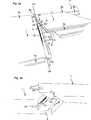
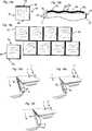
Eine erste bevorzugte Ausführung einer Bodenplatte
Eine erste bevorzugte Ausführung einer Bodenplatte
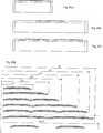
Die Vorderseiten
Um Verbindung der zwei Verbindungskanten in der Richtung D1 und der Richtung D2 zu ermöglichen, weisen die Kanten der Bodenplatte auf an sich bekannte Weise einen Verriegelungsstreifen
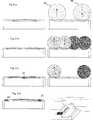
Das mechanische Verriegelungssystem gemäß der Erfindung umfasst eine separate flexible Feder
In dieser Ausführung könnte die Platte
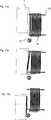
Die flexible Feder
Die Verschiebenut
Die Federnut
Die flexible Feder
Selbst mit Spiel könnte eine genaue Passung zwischen den oberen Verbindungskanten erreicht werden. Die untere Feder-Verschiebefläche
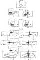
Ein erster wichtiger Vorteil besteht darin, dass die Feder aus recht starrem Material bestehen könnte, das fest und in der vertikalen Richtung stabil ist, während es gleichzeitig in der horizontalen Richtung D2 flexibel sein kann. Die Biegeabschnitte könnten erheblich größer ausgeführt werden als die horizontale Verschiebung, die zum Erreichen der Verriegelung erforderlich ist.A first important advantage is that the spring could be made of fairly rigid material that is strong and stable in the vertical direction, while at the same time being flexible in the horizontal direction D2. The bending sections could be made significantly larger than the horizontal displacement required to achieve the lock.
Ein zweiter Vorteil besteht darin, dass die Teile, die flexibel sind und die erste sowie die zweite horizontale Verschiebung ermöglichen, auch die vertikale Stabilität der Feder gewährleisten. Der Vorteil besteht darin, dass die Gesamtbreite TW der flexiblen Feder und die Tiefe der Verschiebenut recht eingeschränkt sein könnten. Dadurch werden die Festigkeit und die Verformung der Verbindungskante bei Feuchtigkeit verbessert. Als nicht einschränkendes Beispiel kann angeführt werden, dass die Gesamtbreie TW der flexiblen Feder ungefähr 5–15 mm betragen könnte.A second advantage is that the parts, which are flexible and allow the first and second horizontal displacements, also ensure the vertical stability of the spring. The advantage is that the overall width TW of the flexible spring and the depth of the sliding groove could be quite limited. This improves the strength and deformation of the joint edge in moisture. As a non-limiting example, it can be stated that the total width TW of the flexible spring could be about 5-15 mm.
Ein dritter Vorteil besteht darin, dass die flexible Feder aus einem Stück aus einem Material ohne weiche und zusammendrückbare Materialien bestehen könnte. Dadurch verringern sich die Herstellungskosten, und das Befestigen der Feder in der Verschiebenut wird erleichtert.A third advantage is that the flexible spring could be made in one piece from a material without soft and compressible materials. This reduces the manufacturing cost, and the fastening of the spring in the sliding groove is facilitated.
Die Gleitnut ist in dieser bevorzugten Ausführung eine über die gesamte Länge der Verbindungskante durchgehende Nut. Die Verschiebenut
Die Klapp-Platte könnte mit einem nadelförmigen Werkzeug getrennt werden, das von dem Eckenabschnitt
Im Allgemeinen kann jede beliebige Form verwendet werden, die es zulässt, dass sich ein Teil der Feder in Längsrichtung biegen und so zurückfedern könnte, dass der vorstehende Teil mit 0,1 mm oder mehr verschoben werden könnte. Normalerweise sollte die Verschiebung 1–3 mm betragen, jedoch könnten sehr geringe Verschiebungen von ungefähr 0,1 mm ausreichen, um eine vertikale Verriegelung auszubilden, die vertikale Bewegung verhindert, insbesondere bei HDF-Material.In general, any shape may be used that allows a portion of the spring to flex longitudinally and spring back so that the protruding portion could be displaced 0.1 mm or more. Normally, the displacement should be 1-3mm, however, very small displacements of about 0.1mm could be sufficient to form a vertical latch that prevents vertical movement, especially with HDF material.
Innerhalb der Erfindung ist eine Vielzahl von Alternativen möglich, um vertikales Klappen mit einer flexiblen Feder zu erreichen.Within the invention, a variety of alternatives are possible to achieve vertical flap with a flexible spring.
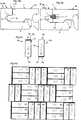
Eine flexible Feder könnte gemäß dem gleichen Prinzip wie bekannte mechanische Vorrichtungen hergestellt werden, die eine Federwirkung ähnlich wie Verriegelungsvorrichtungen erzeugen, die in Türen, Fenstern, Möbeln, Kraftfahrzeugen und Mobiltelefonen eingesetzt werden. Die flexible Feder mit diesen mechanischen Vorrichtungen könnte mit Abmessungen ausgebildet werden, die sich für 6–15 mm starke Böden, insbesondere Holzböden, eignen und in die Kante eingeführt werden.
Insbesondere an langen und breiten Bodenplatten könnten recht komplizierte Vorrichtungen eingesetzt werden, da nur 2–4 Teile pro Quadratmeter Boden erforderlich sind. Selbst bei einem recht hohen Stückpreis sind die Vorteile bei vertikalem Klappen erheblich und könnten recht hohe Kosten für das Verriegelungssystem ausgleichen. Aufgrund der Tatsache, dass die kurzen Seiten nicht sehr häufig gesägt werden, könnten auch Metallbauteile verwendet werden, und diese Komponenten könnten so ausgebildet sein, dass sie sich leicht von der Bodenplatte entfernen lassen, wenn die kurze Seitenkante gesägt werden muss.Especially on long and wide floor panels quite complicated devices could be used, since only 2-4 parts per square meter of floor are required. Even with a fairly high unit price, the benefits of vertical flaps are significant and could offset quite high costs for the latching system. Due to the fact that the short sides are not sawed very often, metal components could also be used and these components could be designed to be easily removed from the bottom plate when the short side edge has to be sawn.
Bei Bodenplatten mit einer Breite von ungefähr 20 cm reicht eine flexible Feder mit einer Länge von wenigen cm aus, wenn sie im Mittelteil der kurzen Seite ungefähr 6–9 cm von dem Eckenabschnitt entfernt positioniert ist.For floor panels approximately 20 cm wide, a flexible spring of a few cm length will suffice if positioned in the middle portion of the short side approximately 6-9 cm from the corner portion.
Die flexible Feder könnte auch, wie dies in der oben angeführten Ausführung beschrieben ist, aus einer einzelnen Komponente mit einer Dicke von lediglich 1 mm bestehen, und könnte verwendet werden, um Bodenplatten mit einer Dicke von bis zu 4 mm zu verbinden. Ein Verriegelungssystem mit der flexiblen Feder gemäß der Erfindung eignet sich auch sehr gut zum Verbinden dickerer Bodenplatten, die ungefähr 10–15 mm stark sind, insbesondere Holz- und Laminat-Bodenplatten. Die Verschiebenut
Alle oben beschriebenen Merkmale der Erfindung könnten miteinander kombiniert oder separat verwendet werden. Die flexiblen Federn könnten mit allen dargestellten Verschiebe- oder Aufnahmenuten kombiniert werden. Die Verriegelungssysteme könnten in jeder dargestellten Verbindung oder Bodenplatte eingesetzt werden. Das System gemäß
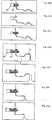
Um die Zugänglichkeit zu verbessern, kann das Werkzeug auch einen gekrümmten Teil umfassen und/oder aus einem elastischen Material hergestellt sein, beispielsweise elastischem biegbarem Kunststoff oder Metall.In order to improve accessibility, the tool may also comprise a curved part and / or be made of an elastic material, for example elastic bendable plastic or metal.
Eine Alternative, für die kein Werkzeug erforderlich ist (
Eine Bodenplatte mit einer flexiblen Feder könnte auch unter Verwendung der herkömmlichen Verfahren aufgenommen werden, die zum Aufnehmen von Bodenplatten mit einer herkömmlichen, nicht flexiblen Feder eingerichtet sind, z. B. Winkeln-Winkeln, Winkeln-Verschieben, Einrasten-Verschieben oder Einrasten-Winkeln.A bottom plate with a flexible spring could also be received using the conventional methods adapted for receiving bottom plates with a conventional, non-flexible spring, e.g. Angle angles, angle shifting, snap-in shifting or snap-in angles.
Eine separate Feder, die in eine Nut eingeführt wird, könnte natürlich hergestellt werden, um Material zu sparen und die Reibungseigenschaften zu verbessern, selbst wenn die Feder nicht flexibel oder verschiebbar ist. Die Verfahren und das Prinzip könnten auch zusammen mit einer flexiblen Feder eingesetzt werden, die sich während des Verriegelns in vertikaler Richtung nach oben und/oder nach unten biegen könnte. Extrudierte V- oder U-förmige Profile, bei denen ein äußerer oder inneren Teil flexibel ist und die wenigstens einen Teil des Profils veranlassen könnten, sich während des vertikalen Klappens im Wesentlichen horizontal zu bewegen, könnten ebenfalls eingesetzt werden, um Bodenplatten gemäß dem gleichen Grundprinzip wie bei der oben beschriebenen flexiblen Feder in einer vertikalen Richtung zu verriegeln.Of course, a separate spring inserted into a groove could be made to save material and improve the friction properties even when the spring is not flexible or slidable. The methods and principle could also be used in conjunction with a flexible spring that could flex up and / or down during locking in the vertical direction. Extruded V- or U-shaped profiles where an outer or inner part is flexible and which could cause at least part of the profile to move substantially horizontally during vertical folding could also be used to make floorboards according to the same basic principle as in the flexible spring described above in a vertical direction to lock.
Das System könnte eingesetzt werden, um fliesenförmige Paneele zu verbinden, die an einer Wand installiert werden, und die Fliesen könnten miteinander und mit einem Verriegelungselement verbunden werden, das an der Wand befestigt ist.The system could be used to connect tile-shaped panels installed on a wall, and the tiles could be joined together and with a locking element attached to the wall.
Die flexible Feder gemäß der Erfindung kann ohne den Verriegelungsstreifen verwendet werden, um nur vertikales Verriegeln zu erreichen.The flexible spring according to the invention can be used without the locking strip to achieve only vertical locking.
In anderen Aspekten kann die Erfindung folgendermaßen beschrieben werden:
- 1. Gruppe von Bodenplatten (
1 ,1' ,1'' ), die im Wesentlichen identisch sind und Verbinder (20 ,30 ,6 ,8 ,14 ) umfassen, die in die Bodenplatten (1 ,1' ,1'' ) (1' ) integriert und so eingerichtet sind, dass sie eine neue Bodenplatte mit einer ersten (1'' ) und einer zweiten (1 ) Bodenplatte so verbinden, dass obere Verbindungskanten der neuen und der zweiten Bodenplatten in verbundenem Zustand eine vertikale Ebene (VP) bilden, wobei ein erster Verbinder (6 ,8 ,14 ) dazu dient, die neue Bodenplatte (1' ) mit der zweiten Bodenplatte (1 ) in einer horizontalen Richtung (D2) senkrecht zu der vertikalen Ebene zu verbinden, und ein zweiter Verbinder (20 ,30 ) dazu dient, die neue Bodenplatte (1' ) mit der zweiten Bodenplatte (1 ) in einer vertikalen Richtung (D1) parallel zu der vertikalen Ebene (VP) zu verbinden, der zweite Verbinder eine flexible Feder (30 ) in einer Verschiebenut (40 ) in einer von der neuen oder der zweiten Bodenplatte umfasst, die Verschiebenut (40 ) in einer Kante der Platte ausgebildet und zu der vertikalen Ebene (VP) hin offen ist, die flexible Feder (30 ) eine Längsrichtung (L) entlang der Verbindungskanten, eine Breite (W) in der horizontalen Ebene senkrecht zu der Länge und eine Dicke (T) in der vertikalen Richtung hat, wobei die flexible Feder dazu dient, in einem verbundenen Zustand mit einer Federnut in der anderen von der neuen oder der zweiten Bodenplatte zusammenzuwirken, der erste Verbinder einen Verriegelungsstreifen (6 ) umfasst, der von der vertikalen Ebene in der zweiten Platte vorsteht und ein Verriegelungselement (8 ) trägt, der Verriegelungsstreifen (6 ) dazu dient, in einem verbundenen Zustand mit einer nach unten offenen Verriegelungsnut (14 ) der neuen Bodenplatte zusammenzuwirken, dadurch gekennzeichnet, dass die neue Bodenplatte so eingerichtet ist, dass sie bei vertikalem Klappen an der ersten und der zweiten Bodenplatte verriegelt wird, ein Teil der flexiblen Feder während des vertikalen Klappens zweimal in der Verschiebenut verschoben wird, wobei eine erste Verschiebung durch das vertikale Klappen der neuen Bodenplatte bewirkt wird, durch das wenigstens ein Teil der flexiblen Feder in der horizontalen Richtung gebogen wird, eine zweite Verschiebung der flexiblen Feder auf ihre Ausgangsposition zu im Wesentlichen durch eine Federwirkung erreicht wird, die durch das Biegen der flexiblen Feder verursacht wird. - 2. Gruppe von
Bodenplatten nach Abschnitt 1, wobei die flexible Feder (30 ) über ihre Länge (L) wenigstens zwei Abschnitte (MS, ES) hat, und die erste oder die zweite Verschiebung eines der Abschnitte größer ist als die erste oder die zweite Verschiebung des anderen der Abschnitte. - 3. Gruppe von
Bodenplatten nach Abschnitt 2, wobei die flexible Feder (30 ) über ihre Länge (L) einen Mittelabschnitt (MS) und zwei Kantenabschnitte (ES) an beiden Seiten des Mittelabschnitts (MS) hat und der Mittelabschnitt (MS) stärker verschoben werden könnte als einer der Kantenabschnitte (ES). - 4. Gruppe von
Bodenplatten nach Abschnitten 1–3, wobei die flexible Feder (30 ) einen vorstehenden Teil (P2), der sich in verbundenem Zustand außerhalb der Verschiebenut (40 ) befindet, sowie einen Nutteil (P1) in der Verschiebenut (40 ) hat, so dass die Größe des vorstehenden Teils (P2) und/oder des Nutteils (P1) über die Länge (L) variiert. - 5. Gruppe von Bodenplatten nach Abschnitt 4, wobei der vorstehende Teil (P2) von einem Eckenabschnitt (
9a ,9b ) der Platte beabstandet ist. - 6. Gruppe von Bodenplatten nach einem der Abschnitte 1
bis 5, wobei die flexible Feder (30 ) aus geformtem Polymermaterial besteht. - 7. Gruppe von
Bodenplatten nach Abschnitt 5, dadurch gekennzeichnet, dass sich das Verriegelungselement (8 ) teilweise in der Verriegelungsnut (14 ) befindet, wenn die erste Verschiebung beginnt. - 8. Gruppe von
Bodenplatten nach Abschnitt 7, wobei sich die flexible Feder (30 ) an der gleichen Kante befindet wie der Verriegelungsstreifen (6 ). - 9. Federrohling (
50 ), bestehend aus wenigstens zwei flexible Federn (30 ), die beide dazu ausgerichtet sind, Bodenplatten (1 ,1' ,1'' ) durch vertikales Klappen zu verbinden, dadurch gekennzeichnet, dass die flexible Feder (30 ) aus geformtem Polymermaterial besteht und dazu dient, in einer Verschiebenut (40 ) befestigt zu werden, und so konfiguriert ist, dass ein Teil der Feder während des vertikalen Klappens zu verschieben ist. - 10. Bodenplatte mit einem Kantenabschnitt, der eine seitlich offene Nut aufweist, in der eine Feder, die als ein separates Teil ausgebildet ist, aufgenommen wird, dadurch gekennzeichnet, dass die Feder so in der Nut angeordnet ist, dass sie in ihrer Längsrichtung und in einer Ebene im Wesentlichen parallel zu einer Hauptebene der Bodenplatte gebogen werden kann, so dass ein Teil der Feder elastisch in der Ebene verschoben werden kann.
- 11.
Bodenplatte nach Abschnitt 10 wobei die Feder (30 ) entlang ihrer Länge (L) wenigstens zwei Abschnitte (MS, ES) aufweist und während der Verschiebung der Feder die Abschnitte in unterschiedlichem Maß verschoben werden. - 12.
Bodenplatte nach Abschnitt 10, wobei die flexible Feder (30 ) über ihre Länge (L) einen Mittelabschnitt (MS) und zwei Kantenabschnitte (ES) auf beiden Seiten des Mittelabschnitts (MS) hat und der Mittelabschnitt (MS) in größerem Maß verschoben werden kann als die Kantenabschnitte (ES). - 13. Werkzeug (
100 ,101 ,102 ,103 ) zum Aufnehmen von Bodenplatten, dadurch gekennzeichnet, dass das Werkzeug einen Griffteil (104 ) und einen Werkzeugteil (105 ) umfasst, der so ausgebildet ist, dass er in eine Federnut oder eine Verschiebenut einer Bodenplatte einsetzbar ist. - 14.
Werkzeug nach Abschnitt 13, wobei der Werkzeugteil (105 ) länglich ist und wenn er in die Federnut eingeführt wird, eine flexible Feder einer angrenzenden Bodenplatte aus der Federnut herausschiebt. - 15.
Werkzeug nach Abschnitt 13, wobei der Werkzeugteil (105 ) einen Vorsprung oder eine Aussparung umfasst, die zum Ergreifen eines Endteils der Feder eingerichtet ist, der ein Vorsprung oder eine Vertiefung ist. - 16. Werkzeug nach einem der Abschnitte 13–15, wobei der Werkzeugteil (
105 ) aus einem elastischen Material, z. B. Kunststoff oder elastischem biegbarem Metall, besteht. - 17. Werkzeug nach einem der Abschnitte 13–15, wobei wenigstens der Werkzeugteil (
105 ) gekrümmt ist.
- 1. group of floor slabs (
1 .1' .1'' ), which are essentially identical, and connectors (20 .30 .6 .8th .14 ), which are in the bottom plates (1 .1' .1'' ) (1' ) are integrated and arranged so that they have a new bottom plate with a first (1'' ) and a second (1 ) Connect the bottom plate so that upper connecting edges of the new and the second bottom plates in the connected state form a vertical plane (VP), wherein a first connector (6 .8th .14 ) serves, the new floor plate (1' ) with the second bottom plate (1 ) in a horizontal direction (D2) perpendicular to the vertical plane, and a second connector (20 .30 ) serves, the new floor plate (1' ) with the second bottom plate (1 ) in a vertical direction (D1) parallel to the vertical plane (VP), the second connector a flexible spring (30 ) in a sliding groove (40 ) in one of the new or the second bottom plate, the sliding groove (40 ) is formed in an edge of the plate and is open to the vertical plane (VP), the flexible spring (30 ) has a longitudinal direction (L) along the joint edges, a width (W) in the horizontal plane perpendicular to the length, and a thickness (T) in the vertical direction, the flexible spring serving to engage a tongue groove in a connected state the other of the new or the second bottom plate cooperate, the first connector a locking strip (6 ) projecting from the vertical plane in the second plate and a locking element (8th ), the locking strip (6 ) serves, in a connected state, with one down open locking groove (14 ) of the new floor panel, characterized in that the new floor panel is adapted to be locked to the first and second floor panels when vertically hinged, a portion of the flexible tongue is displaced twice in the sliding groove during vertical folding, with a first floor panel causing first displacement by the vertical flaps of the new bottom plate, by which at least a part of the flexible spring is bent in the horizontal direction, a second displacement of the flexible spring to its initial position is achieved by substantially a spring action caused by the bending of the flexible spring is caused. - 2. group of floor panels according to
section 1, wherein the flexible spring (30 ) has at least two sections (MS, ES) over its length (L), and the first or second displacement of one of the sections is greater than the first or second displacement of the other of the sections. - 3. group of floor panels according to
section 2, wherein the flexible spring (30 ) over its length (L) has a central portion (MS) and two edge portions (ES) on both sides of the central portion (MS) and the central portion (MS) could be displaced more than one of the edge portions (ES). - 4. group of floor slabs according to sections 1-3, whereby the flexible spring (
30 ) a projecting part (P2), which in connected state outside the Verschiebenut (40 ), and a groove part (P1) in the sliding groove (40 ) so that the size of the protruding part (P2) and / or the groove part (P1) varies over the length (L). - 5. group of floor panels according to section 4, wherein the protruding part (P2) of a corner portion (
9a .9b ) of the plate is spaced. - 6. group of floor panels according to any one of
sections 1 to 5, wherein the flexible spring (30 ) consists of molded polymer material. - 7. group of floor panels according to
Section 5, characterized in that the locking element (8th ) partially in the locking groove (14 ) when the first shift begins. - 8. group of floor panels according to
section 7, wherein the flexible spring (30 ) is located at the same edge as the locking strip (6 ). - 9. spring blank (
50 ), consisting of at least two flexible springs (30 ), both of which are oriented to1 .1' .1'' ) by vertical flaps, characterized in that the flexible spring (30 ) consists of molded polymer material and serves in a sliding groove (40 ), and configured to shift part of the spring during vertical folding. - 10. base plate having an edge portion having a laterally open groove, in which a spring, which is formed as a separate part, is received, characterized in that the spring is arranged in the groove so that they in their longitudinal direction and in a plane substantially parallel to a main plane of the bottom plate can be bent, so that a part of the spring can be elastically displaced in the plane.
- 11. Base plate according to
section 10, with the spring (30 ) along its length (L) at least two sections (MS, ES) and during the displacement of the spring, the sections are moved to different degrees. - 12. Base plate according to
section 10, wherein the flexible spring (30 ) has along its length (L) a central portion (MS) and two edge portions (ES) on both sides of the central portion (MS) and the central portion (MS) can be displaced to a greater extent than the edge portions (ES). - 13. Tool (
100 .101 .102 .103 ) for receiving floor slabs, characterized in that the tool has a handle part (104 ) and a tool part (105 ) adapted to be inserted into a spring groove or a sliding groove of a floor panel. - 14. Tool according to
section 13, wherein the tool part (105 ) is elongate and when inserted into the spring groove, pushes out a flexible spring of an adjacent bottom plate from the spring groove. - 15. Tool according to
section 13, wherein the tool part (105 ) comprises a projection or recess adapted to engage an end portion of the spring which is a projection or a recess. - 16. Tool according to one of the sections 13-15, wherein the tool part (
105 ) made of an elastic material, for. As plastic or elastic bendable metal exists. - 17. Tool according to one of the sections 13-15, wherein at least the tool part (
105 ) is curved.
ZITATE ENTHALTEN IN DER BESCHREIBUNG QUOTES INCLUDE IN THE DESCRIPTION
Diese Liste der vom Anmelder aufgeführten Dokumente wurde automatisiert erzeugt und ist ausschließlich zur besseren Information des Lesers aufgenommen. Die Liste ist nicht Bestandteil der deutschen Patent- bzw. Gebrauchsmusteranmeldung. Das DPMA übernimmt keinerlei Haftung für etwaige Fehler oder Auslassungen.This list of the documents listed by the applicant has been generated automatically and is included solely for the better information of the reader. The list is not part of the German patent or utility model application. The DPMA assumes no liability for any errors or omissions.
Zitierte PatentliteraturCited patent literature
- WO 01/0248127[0016]WO 01/0248127[0016]
- WO 03/083234[0017, 0017, 0021]WO 03/083234[0017, 0017, 0021]
Claims (4)
Translated fromGermanApplications Claiming Priority (2)
| Application Number | Priority Date | Filing Date | Title |
|---|---|---|---|
| EP04025167 | 2004-10-22 | ||
| EP04025167AEP1650375B2 (en) | 2004-10-22 | 2004-10-22 | A set of floor panels |
Publications (1)
| Publication Number | Publication Date |
|---|---|
| DE202005022095U1true DE202005022095U1 (en) | 2013-07-11 |
Family
ID=34927082
Family Applications (8)
| Application Number | Title | Priority Date | Filing Date |
|---|---|---|---|
| DE602004010914TExpired - LifetimeDE602004010914T3 (en) | 2004-10-22 | 2004-10-22 | Set of floor panels |
| DE202005021864UExpired - LifetimeDE202005021864U1 (en) | 2004-10-22 | 2005-10-21 | Mechanical locking of floor panels with a flexible spring |
| DE202005021702UExpired - LifetimeDE202005021702U1 (en) | 2004-10-22 | 2005-10-21 | Mechanical locking of floor panels with a flexible spring |
| DE202005022097UExpired - LifetimeDE202005022097U1 (en) | 2004-10-22 | 2005-10-21 | Mechanical locking of floor panels with a flexible spring |
| DE202005022095UExpired - LifetimeDE202005022095U1 (en) | 2004-10-22 | 2005-10-21 | Mechanical locking of floor panels with a flexible spring |
| DE202005021889UExpired - LifetimeDE202005021889U1 (en) | 2004-10-22 | 2005-10-21 | Device for providing floorboards with a flexible spring |
| DE202005022094UExpired - LifetimeDE202005022094U1 (en) | 2004-10-22 | 2005-10-21 | building slab |
| DE202005021865UExpired - LifetimeDE202005021865U1 (en) | 2004-10-22 | 2005-10-21 | Mechanical locking of floor panels with a flexible spring |
Family Applications Before (4)
| Application Number | Title | Priority Date | Filing Date |
|---|---|---|---|
| DE602004010914TExpired - LifetimeDE602004010914T3 (en) | 2004-10-22 | 2004-10-22 | Set of floor panels |
| DE202005021864UExpired - LifetimeDE202005021864U1 (en) | 2004-10-22 | 2005-10-21 | Mechanical locking of floor panels with a flexible spring |
| DE202005021702UExpired - LifetimeDE202005021702U1 (en) | 2004-10-22 | 2005-10-21 | Mechanical locking of floor panels with a flexible spring |
| DE202005022097UExpired - LifetimeDE202005022097U1 (en) | 2004-10-22 | 2005-10-21 | Mechanical locking of floor panels with a flexible spring |
Family Applications After (3)
| Application Number | Title | Priority Date | Filing Date |
|---|---|---|---|
| DE202005021889UExpired - LifetimeDE202005021889U1 (en) | 2004-10-22 | 2005-10-21 | Device for providing floorboards with a flexible spring |
| DE202005022094UExpired - LifetimeDE202005022094U1 (en) | 2004-10-22 | 2005-10-21 | building slab |
| DE202005021865UExpired - LifetimeDE202005021865U1 (en) | 2004-10-22 | 2005-10-21 | Mechanical locking of floor panels with a flexible spring |
Country Status (28)
| Country | Link |
|---|---|
| US (7) | US8341915B2 (en) |
| EP (29) | EP1650375B2 (en) |
| JP (1) | JP4652411B2 (en) |
| KR (1) | KR101206400B1 (en) |
| CN (2) | CN100547206C (en) |
| AT (3) | ATE535660T1 (en) |
| AU (1) | AU2005296349B2 (en) |
| BR (1) | BRPI0516331B1 (en) |
| CA (1) | CA2581678C (en) |
| CY (1) | CY1107360T1 (en) |
| DE (8) | DE602004010914T3 (en) |
| DK (4) | DK1936068T3 (en) |
| ES (6) | ES2378330T3 (en) |
| HU (2) | HUE043159T2 (en) |
| IL (1) | IL182264A (en) |
| LT (3) | LT2388399T (en) |
| MX (1) | MX2007004786A (en) |
| MY (1) | MY139000A (en) |
| NO (1) | NO338585B1 (en) |
| NZ (1) | NZ554905A (en) |
| PL (11) | PL1936068T3 (en) |
| PT (5) | PT1650375E (en) |
| RU (1) | RU2373348C2 (en) |
| SI (3) | SI1650375T2 (en) |
| TR (4) | TR201901831T4 (en) |
| UA (1) | UA90282C2 (en) |
| WO (1) | WO2006043893A1 (en) |
| ZA (1) | ZA200704038B (en) |
Cited By (1)
| Publication number | Priority date | Publication date | Assignee | Title |
|---|---|---|---|---|
| DE102013225358A1 (en)* | 2013-12-10 | 2015-06-11 | Laminatepark Gmbh & Co. Kg | Panel with locking element |
Families Citing this family (382)
| Publication number | Priority date | Publication date | Assignee | Title |
|---|---|---|---|---|
| US7131242B2 (en) | 1995-03-07 | 2006-11-07 | Pergo (Europe) Ab | Flooring panel or wall panel and use thereof |
| SE9500810D0 (en) | 1995-03-07 | 1995-03-07 | Perstorp Flooring Ab | Floor tile |
| US7992358B2 (en) | 1998-02-04 | 2011-08-09 | Pergo AG | Guiding means at a joint |
| SE512290C2 (en) | 1998-06-03 | 2000-02-28 | Valinge Aluminium Ab | Locking system for mechanical joining of floorboards and floorboard provided with the locking system |
| SE514645C2 (en) | 1998-10-06 | 2001-03-26 | Perstorp Flooring Ab | Floor covering material comprising disc-shaped floor elements intended to be joined by separate joint profiles |
| SE517478C2 (en) | 1999-04-30 | 2002-06-11 | Valinge Aluminium Ab | Locking system for mechanical hoisting of floorboards, floorboard provided with the locking system and method for producing mechanically foldable floorboards |
| SE517183C2 (en) | 2000-01-24 | 2002-04-23 | Valinge Aluminium Ab | Locking system for mechanical joining of floorboards, floorboard provided with the locking system and method for making such floorboards |
| SE518184C2 (en) | 2000-03-31 | 2002-09-03 | Perstorp Flooring Ab | Floor covering material comprising disc-shaped floor elements which are joined together by means of interconnecting means |
| US8028486B2 (en) | 2001-07-27 | 2011-10-04 | Valinge Innovation Ab | Floor panel with sealing means |
| US8250825B2 (en) | 2001-09-20 | 2012-08-28 | Välinge Innovation AB | Flooring and method for laying and manufacturing the same |
| SE525661C2 (en) | 2002-03-20 | 2005-03-29 | Vaelinge Innovation Ab | Floor boards decorative joint portion making system, has surface layer with underlying layer such that adjoining edge with surface has underlying layer parallel to horizontal plane |
| ATE467015T1 (en)* | 2002-04-03 | 2010-05-15 | Vaelinge Innovation Ab | FLOOR PANEL WITH INTEGRATED CONNECTING MEANS AND METHOD FOR THE PRODUCTION THEREOF |
| US7739849B2 (en)* | 2002-04-22 | 2010-06-22 | Valinge Innovation Ab | Floorboards, flooring systems and methods for manufacturing and installation thereof |
| US20040206036A1 (en) | 2003-02-24 | 2004-10-21 | Valinge Aluminium Ab | Floorboard and method for manufacturing thereof |
| US7845140B2 (en) | 2003-03-06 | 2010-12-07 | Valinge Innovation Ab | Flooring and method for installation and manufacturing thereof |
| SE0300642D0 (en)* | 2003-03-11 | 2003-03-11 | Pergo Europ Ab | Process for sealing a joint |
| SE526688C2 (en) | 2003-11-20 | 2005-10-25 | Pergo Europ Ab | Method of joining panels where a locking rod is inserted into a locking groove or locking cavity |
| US7886497B2 (en) | 2003-12-02 | 2011-02-15 | Valinge Innovation Ab | Floorboard, system and method for forming a flooring, and a flooring formed thereof |
| US20050166516A1 (en) | 2004-01-13 | 2005-08-04 | Valinge Aluminium Ab | Floor covering and locking systems |
| SE527570C2 (en) | 2004-10-05 | 2006-04-11 | Vaelinge Innovation Ab | Device and method for surface treatment of sheet-shaped material and floor board |
| ES2378330T3 (en)* | 2004-10-22 | 2012-04-11 | Välinge Innovation AB | A method of providing floor panels with a mechanical locking system |
| US7454875B2 (en) | 2004-10-22 | 2008-11-25 | Valinge Aluminium Ab | Mechanical locking system for floor panels |
| US7841144B2 (en) | 2005-03-30 | 2010-11-30 | Valinge Innovation Ab | Mechanical locking system for panels and method of installing same |
| DE102004062648B4 (en)* | 2004-12-21 | 2006-09-07 | Kronotec Ag | Device for inserting springs in the front and / or long sides of technical wood products |
| US8215078B2 (en) | 2005-02-15 | 2012-07-10 | Välinge Innovation Belgium BVBA | Building panel with compressed edges and method of making same |
| BE1016938A6 (en) | 2005-03-31 | 2007-10-02 | Flooring Ind Ltd | Floor panel manufacturing method, involves providing panels at lower side with guiding groove and providing two opposite sides with profiled edge regions that comprise coupling parts |
| US20130139478A1 (en) | 2005-03-31 | 2013-06-06 | Flooring Industries Limited, Sarl | Methods for packaging floor panels, as well as packed set of floor panels |
| US8061104B2 (en) | 2005-05-20 | 2011-11-22 | Valinge Innovation Ab | Mechanical locking system for floor panels |
| SE529076C2 (en)* | 2005-07-11 | 2007-04-24 | Pergo Europ Ab | A joint for panels |
| US20070175144A1 (en) | 2006-01-11 | 2007-08-02 | Valinge Innovation Ab | V-groove |
| SE530653C2 (en) | 2006-01-12 | 2008-07-29 | Vaelinge Innovation Ab | Moisture-proof floor board and floor with an elastic surface layer including a decorative groove |
| DE102006011887A1 (en) | 2006-01-13 | 2007-07-19 | Akzenta Paneele + Profile Gmbh | Blocking element, panel with separate blocking element, method of installing a panel covering of panels with blocking elements, and method and device for pre-assembling a blocking element on a panel |
| DE102006006124A1 (en)* | 2006-02-10 | 2007-08-23 | Flooring Technologies Ltd. | Device for locking two building panels |
| BE1017157A3 (en) | 2006-06-02 | 2008-03-04 | Flooring Ind Ltd | FLOOR COVERING, FLOOR ELEMENT AND METHOD FOR MANUFACTURING FLOOR ELEMENTS. |
| SE533410C2 (en) | 2006-07-11 | 2010-09-14 | Vaelinge Innovation Ab | Floor panels with mechanical locking systems with a flexible and slidable tongue as well as heavy therefore |
| US7861482B2 (en) | 2006-07-14 | 2011-01-04 | Valinge Innovation Ab | Locking system comprising a combination lock for panels |
| SE531110C2 (en)* | 2006-07-14 | 2008-12-23 | Vaelinge Innovation Ab | Locking system comprising a combination lock for panels |
| DE102006037614B3 (en)* | 2006-08-10 | 2007-12-20 | Guido Schulte | Floor covering, has head spring pre-assembled in slot and protruding over end of slot, and wedge surface formed at slot or head spring such that head spring runs into wedge surface by shifting projecting end of head spring into slot |
| US8323016B2 (en) | 2006-09-15 | 2012-12-04 | Valinge Innovation Belgium Bvba | Device and method for compressing an edge of a building panel and a building panel with compressed edges |
| US8689512B2 (en) | 2006-11-15 | 2014-04-08 | Valinge Innovation Ab | Mechanical locking of floor panels with vertical folding |
| SE532607C2 (en)* | 2006-11-15 | 2010-03-02 | Vaelinge Innovation Ab | Mechanical locking of vertical paneling floor panels |
| PL2570565T3 (en)* | 2006-11-15 | 2019-05-31 | Vaelinge Innovation Ab | Mechanical locking of floor panels with vertical folding |
| US11725394B2 (en) | 2006-11-15 | 2023-08-15 | Välinge Innovation AB | Mechanical locking of floor panels with vertical folding |
| DE102006057491A1 (en)* | 2006-12-06 | 2008-06-12 | Akzenta Paneele + Profile Gmbh | Panel and flooring |
| SE531111C2 (en) | 2006-12-08 | 2008-12-23 | Vaelinge Innovation Ab | Mechanical locking of floor panels |
| DE202007000310U1 (en)* | 2007-01-03 | 2007-04-19 | Akzenta Paneele + Profile Gmbh | Panel for floor covering has vertical locking element with complementary hook elements that are configured so that connected panels can be unlocked from their hooked and vertically locked state |
| DE102007002590A1 (en)* | 2007-01-12 | 2008-07-31 | Akzenta Paneele + Profile Gmbh | Panel and flooring |
| DE102007020271A1 (en) | 2007-02-01 | 2008-08-07 | August Hipper | Floor panel connector, has catch lug extending over area of longitudinal edges or front sides of panel, and locking part formed by circumference wall of window, where locking lug or catch lug extends through locking part in locked condition |
| DE202007018998U1 (en) | 2007-02-21 | 2010-03-04 | Hamberger Industriewerke Gmbh | Connection for plate-shaped components |
| DE202007018662U1 (en) | 2007-03-26 | 2009-02-19 | Kronotec Ag | Panel, in particular floor panel |
| US20080236431A1 (en) | 2007-03-28 | 2008-10-02 | Pergo (Europe) Ab | Process for Color Variability in Printing to Simulate Color Variation of Natural Product |
| DE102007026342B4 (en)* | 2007-06-06 | 2013-11-28 | Laminatepark Gmbh & Co. Kg | Set of tabular panels with movable locking element |
| DE102007063837B3 (en) | 2007-06-06 | 2020-01-23 | Laminatepark Gmbh & Co. Kg | Set of panel-shaped panels with a movable locking element |
| DE102007032885B4 (en) | 2007-07-14 | 2016-01-14 | Flooring Technologies Ltd. | Panel, in particular floor panel and means for locking interconnected panels |
| DE102007049792A1 (en) | 2007-08-10 | 2009-02-19 | Hamberger Industriewerke Gmbh | connection |
| DE202008005295U1 (en) | 2007-08-10 | 2008-10-23 | Hamberger Industriewerke Gmbh | connection |
| DE102007042250B4 (en) | 2007-09-06 | 2010-04-22 | Flooring Technologies Ltd. | Device for connecting and locking two building panels, in particular floor panels |
| DE102007042840B4 (en)* | 2007-09-10 | 2010-04-22 | Flooring Technologies Ltd. | Panel, in particular floor panel |
| US8353140B2 (en) | 2007-11-07 | 2013-01-15 | Valinge Innovation Ab | Mechanical locking of floor panels with vertical snap folding |
| US8499521B2 (en) | 2007-11-07 | 2013-08-06 | Valinge Innovation Ab | Mechanical locking of floor panels with vertical snap folding and an installation method to connect such panels |
| PL2602077T3 (en) | 2007-11-19 | 2017-12-29 | Välinge Innovation AB | Recycling of laminate floorings |
| US9783996B2 (en) | 2007-11-19 | 2017-10-10 | Valinge Innovation Ab | Fibre based panels with a wear resistance surface |
| PL3072653T3 (en) | 2007-11-19 | 2022-08-22 | Välinge Innovation AB | Method of manufacturing a building panel |
| BE1018600A5 (en) | 2007-11-23 | 2011-04-05 | Flooring Ind Ltd Sarl | FLOOR PANEL. |
| DE102007062430B3 (en)* | 2007-12-20 | 2009-07-02 | Flooring Technologies Ltd. | Method for machining a side edge of a panel and apparatus for carrying out the method |
| DE102008003117B4 (en) | 2008-01-02 | 2011-01-27 | Flooring Technologies Ltd. | Device for locking two building panels |
| US20100285289A1 (en)* | 2008-01-09 | 2010-11-11 | Oke Nollet | Floor covering, formed from floor panels and method for manufacturing such floor panels |
| DE102008003550B4 (en) | 2008-01-09 | 2009-10-22 | Flooring Technologies Ltd. | Device and method for locking two floor panels |
| MY152779A (en) | 2008-01-31 | 2014-11-28 | Valinge Innovation Ab | Mechanical locking of floor panels, methods to install and uninstall panels, a method and an equipment to produce the locking system, a method to connect a displaceable tongue to a panel and a tongue blank |
| US8505257B2 (en) | 2008-01-31 | 2013-08-13 | Valinge Innovation Ab | Mechanical locking of floor panels |
| US8419877B2 (en) | 2008-04-07 | 2013-04-16 | Ceraloc Innovation Belgium Bvba | Wood fibre based panels with a thin surface layer |
| US11235565B2 (en) | 2008-04-07 | 2022-02-01 | Valinge Innovation Ab | Wood fibre based panels with a thin surface layer |
| US8112967B2 (en) | 2008-05-15 | 2012-02-14 | Valinge Innovation Ab | Mechanical locking of floor panels |
| DE102008030281B3 (en)* | 2008-06-30 | 2009-10-29 | Guido Schulte | Method for inserting spring into longitudinal or head-sided groove in element plate of floor covering, involves releasing springs from transition belt and shifting springs into groove in element plates for locking plates with one another |
| DE102008031167B4 (en)* | 2008-07-03 | 2015-07-09 | Flooring Technologies Ltd. | Method for connecting and locking glueless laying floor panels |
| DE202008011589U1 (en)* | 2008-09-01 | 2008-11-27 | Akzenta Paneele + Profile Gmbh | Plastic floor panel with mechanical locking edges |
| DE102008047098B3 (en)* | 2008-09-12 | 2010-04-08 | Guido Schulte | flooring |
| DE102008047099B4 (en)* | 2008-09-12 | 2010-05-12 | Guido Schulte | flooring |
| US20100221493A1 (en) | 2008-11-21 | 2010-09-02 | Mats Hintze | Use of silane-treated particles in laminates to improve clarity |
| EP2376722A1 (en) | 2008-12-16 | 2011-10-19 | HAMBERGER INDUSTRIEWERKE GmbH | Floor covering |
| BE1018389A3 (en) | 2008-12-17 | 2010-10-05 | Unilin Bvba | COMPOSITE ELEMENT, MULTI-LAYER PLATE AND PANEL-SHAPED ELEMENT FOR FORMING SUCH COMPOSITE ELEMENT. |
| US8316612B2 (en)* | 2008-12-18 | 2012-11-27 | Radva Corporation | Pre-insulated structural building panels |
| BE1018627A5 (en) | 2009-01-16 | 2011-05-03 | Flooring Ind Ltd Sarl | FLOOR PANEL. |
| WO2010087752A1 (en)* | 2009-01-30 | 2010-08-05 | Välinge Innovation Belgium BVBA | Mechanical lockings of floor panels and a tongue blank |
| PL2226447T3 (en)* | 2009-02-27 | 2012-10-31 | Vaelinge Innovation Ab | Panelling, in particular floor panelling |
| CH700513A2 (en)* | 2009-03-10 | 2010-09-15 | Innovaris Ag | Panels. |
| DE102009013472A1 (en) | 2009-03-19 | 2010-09-23 | Wemhöner Systems Technologies AG | Method for inserting spring into groove at side edge of floor covering, involves engaging free spring end by squeezing unit that is arranged laterally in conveying path and squeezed into groove |
| EP2236694A1 (en)* | 2009-03-25 | 2010-10-06 | Spanolux N.V.- DIV. Balterio | A fastening system and a panel |
| DE102009016520A1 (en) | 2009-04-08 | 2010-10-28 | Hamberger Industriewerke Gmbh | Panel and process for its production |
| BE1018728A3 (en) | 2009-04-22 | 2011-07-05 | Flooring Ind Ltd Sarl | FLOOR PANEL. |
| EP2270291B1 (en) | 2009-06-08 | 2011-05-18 | Flooring Technologies Ltd. | Set of building panels with device for locking two of these panels |
| NL2003019C2 (en)* | 2009-06-12 | 2010-12-15 | 4Sight Innovation Bv | FLOOR PANEL AND FLOOR COVERAGE CONSISING OF MULTIPLE OF SUCH FLOOR PANELS. |
| BE1018802A3 (en)* | 2009-06-29 | 2011-09-06 | Flooring Ind Ltd Sarl | PANEL, MORE SPECIAL FLOOR PANEL. |
| DE102009034902B4 (en)* | 2009-07-27 | 2015-10-01 | Guido Schulte | Surface made of mechanically interconnectable panels |
| DE102009034903B3 (en)* | 2009-07-27 | 2011-01-20 | Guido Schulte | Surface made of mechanically interconnectable panels |
| CN102574292B (en) | 2009-07-31 | 2016-05-18 | 瓦林格创新股份有限公司 | Process relevant method and apparatus to the edge of building panelling |
| US11717901B2 (en) | 2009-07-31 | 2023-08-08 | Valinge Innovation Ab | Methods and arrangements relating to edge machining of building panels |
| US8931174B2 (en) | 2009-07-31 | 2015-01-13 | Valinge Innovation Ab | Methods and arrangements relating to edge machining of building panels |
| US8365499B2 (en) | 2009-09-04 | 2013-02-05 | Valinge Innovation Ab | Resilient floor |
| PL2473687T3 (en) | 2009-09-04 | 2019-10-31 | Vaelinge Innovation Ab | A method of assembling resilient floorboards which are provided with a mechanical locking system |
| US11725395B2 (en) | 2009-09-04 | 2023-08-15 | Välinge Innovation AB | Resilient floor |
| DE102009041297B4 (en)* | 2009-09-15 | 2018-10-11 | Guido Schulte | Coating of mechanically interconnectable elements and a process for the production of elements |
| DE102009046689A1 (en)* | 2009-11-13 | 2011-05-19 | Peri Gmbh | An element |
| BE1019008A3 (en) | 2009-11-20 | 2011-12-06 | Flooring Ind Ltd Sarl | FLOOR PANEL. |
| BR112012013809B1 (en) | 2009-12-17 | 2019-07-30 | Välinge Innovation AB | METHOD FOR MANUFACTURING FLOOR PANELS |
| PT2339092T (en) | 2009-12-22 | 2019-07-19 | Flooring Ind Ltd Sarl | Method for producing covering panels |
| PL4092213T3 (en) | 2010-01-11 | 2024-03-25 | Välinge Innovation AB | Floor covering with interlocking design |
| BR112012016569A2 (en) | 2010-01-12 | 2016-04-05 | Vaelinge Innovation Ab | mechanical locking system for floor panels |
| BR112012017589B1 (en) | 2010-01-14 | 2019-11-12 | Spanolux N V Div Balterio | floor panel mounting |
| PL2523805T3 (en) | 2010-01-15 | 2018-06-29 | Välinge Innovation AB | Fibre based panels with a decorative wear resistance surface |
| EP2523808A4 (en) | 2010-01-15 | 2017-01-04 | Välinge Innovation AB | Fibre based panels with a decorative wear resistance surface |
| MX2012007874A (en) | 2010-01-15 | 2012-08-03 | Ceraloc Innovation Belgium | Bright colored surface layer. |
| US20110177319A1 (en) | 2010-01-15 | 2011-07-21 | Valinge Innovation Belgium Bvba | Heat and pressure generated design |
| DE102010004717A1 (en) | 2010-01-15 | 2011-07-21 | Pergo (Europe) Ab | Set of panels comprising retaining profiles with a separate clip and method for introducing the clip |
| US8234830B2 (en) | 2010-02-04 | 2012-08-07 | Välinge Innovations AB | Mechanical locking system for floor panels |
| CA2786680C (en) | 2010-02-04 | 2018-06-12 | Vaelinge Innovation Ab | Mechanical locking system for floor panels and a tongue therefore |
| CN102199944A (en)* | 2010-03-26 | 2011-09-28 | 何其佳 | Architectural decorative plate and flexible false tongue used for connection of architectural decorative plates |
| US10899166B2 (en) | 2010-04-13 | 2021-01-26 | Valinge Innovation Ab | Digitally injected designs in powder surfaces |
| US8480841B2 (en) | 2010-04-13 | 2013-07-09 | Ceralog Innovation Belgium BVBA | Powder overlay |
| CN102844506B (en) | 2010-04-15 | 2015-08-12 | 巴尔特利奥-斯巴诺吕克斯股份公司 | floor components |
| BE1019331A5 (en) | 2010-05-10 | 2012-06-05 | Flooring Ind Ltd Sarl | FLOOR PANEL AND METHODS FOR MANUFACTURING FLOOR PANELS. |
| BE1019501A5 (en) | 2010-05-10 | 2012-08-07 | Flooring Ind Ltd Sarl | FLOOR PANEL AND METHOD FOR MANUFACTURING FLOOR PANELS. |
| CN104831904B (en)* | 2010-05-10 | 2017-05-24 | 佩尔戈(欧洲)股份公司 | Set of panels |
| DE102010021436A1 (en) | 2010-05-25 | 2011-12-01 | Hamberger Industriewerke Gmbh | Connection for two panels |
| US20110293904A1 (en) | 2010-05-27 | 2011-12-01 | Pergo AG | Method for manufacturing a surface element |
| US10315219B2 (en) | 2010-05-31 | 2019-06-11 | Valinge Innovation Ab | Method of manufacturing a panel |
| EP2575542B1 (en) | 2010-06-03 | 2021-03-10 | Unilin, BV | Composed element and corner connection applied herewith |
| US20130097959A1 (en) | 2010-06-30 | 2013-04-25 | Kreafin Group Sa | Panel With Improved Coupling Means |
| DE102011000013A1 (en) | 2010-08-04 | 2012-02-09 | Hamberger Industriewerke Gmbh | Surface elastic floor and mounting module |
| DE102010047752A1 (en) | 2010-10-08 | 2012-04-12 | Pergo AG | cover assembly |
| US8591696B2 (en) | 2010-11-17 | 2013-11-26 | Pergo (Europe) Ab | Method for manufacturing a surface element |
| DE102010063976B4 (en)* | 2010-12-22 | 2013-01-17 | Akzenta Paneele + Profile Gmbh | paneling |
| CN102619323A (en)* | 2011-01-27 | 2012-08-01 | 张国平 | Plastic material barb type lock floor |
| DE102011000546B4 (en)* | 2011-02-07 | 2016-03-24 | Fabian von Ferrari | Connection system, in particular for furniture |
| US8806832B2 (en) | 2011-03-18 | 2014-08-19 | Inotec Global Limited | Vertical joint system and associated surface covering system |
| WO2012141651A1 (en) | 2011-04-12 | 2012-10-18 | Ceraloc Innovation Belgium Bvba | Method of manufacturing a layer |
| MX342546B (en) | 2011-04-12 | 2016-10-03 | Vaelinge Innovation Ab | POWDER COMPENSATOR COAT. |
| MX352832B (en) | 2011-04-12 | 2017-12-08 | Vaelinge Innovation Ab | A powder mix and a method for producing a building panel. |
| ES2805332T3 (en) | 2011-04-12 | 2021-02-11 | Vaelinge Innovation Ab | Manufacturing method of a building panel |
| US9010067B2 (en)* | 2011-04-14 | 2015-04-21 | Geoffrey Alan Baker | Fabricating the locking steps in the groove element of spring-loaded split-tongue locking connector system |
| CA2831349C (en)* | 2011-04-15 | 2017-12-19 | i-TeConsult n.v | Surface covering kit comprising panels and an extraneous locking element |
| PL2520737T3 (en)* | 2011-05-03 | 2017-08-31 | Barlinek S.A. | Construction panel with a device for connection with at least one further construction panel on a base |
| UA109938C2 (en) | 2011-05-06 | 2015-10-26 | MECHANICAL LOCKING SYSTEM FOR CONSTRUCTION PANELS | |
| BE1020044A5 (en) | 2011-06-29 | 2013-04-02 | Unilin Bvba | TRAY, TRAY CONSTRUCTION AND METHOD FOR MANUFACTURING A TRAY. |
| UA114715C2 (en)* | 2011-07-05 | 2017-07-25 | Сералок Інновейшн Аб | Mechanical locking of floor panels with a glued tongue |
| US9725912B2 (en) | 2011-07-11 | 2017-08-08 | Ceraloc Innovation Ab | Mechanical locking system for floor panels |
| RU2603987C2 (en)* | 2011-07-11 | 2016-12-10 | Сералок Инновейшн Аб | Mechanical locking system for floor panels |
| US8650826B2 (en) | 2011-07-19 | 2014-02-18 | Valinge Flooring Technology Ab | Mechanical locking system for floor panels |
| HUE030211T2 (en)* | 2011-07-19 | 2017-04-28 | Ceraloc Innovation Ab | Mechanical locking system for building elements |
| DE102012105793A1 (en) | 2011-07-29 | 2013-01-31 | Hamberger Industriewerke Gmbh | Connection for elastic or plate-shaped components and floor covering |
| DE102012102339A1 (en) | 2011-07-29 | 2013-01-31 | Hamberger Industriewerke Gmbh | Connection for elastic or plate-shaped components, profile slides and floor coverings |
| DE102011052335B4 (en)* | 2011-08-01 | 2015-09-17 | Guido Schulte | Cover made of mechanically interconnectable panels and method for producing such panels |
| US8857126B2 (en) | 2011-08-15 | 2014-10-14 | Valinge Flooring Technology Ab | Mechanical locking system for floor panels |
| US8769905B2 (en) | 2011-08-15 | 2014-07-08 | Valinge Flooring Technology Ab | Mechanical locking system for floor panels |
| US8763340B2 (en)* | 2011-08-15 | 2014-07-01 | Valinge Flooring Technology Ab | Mechanical locking system for floor panels |
| UA110987C2 (en)* | 2011-08-15 | 2016-03-10 | Велінге Флорінг Текнолоджи Аб | Mechanical interlock system for floor panels |
| CN103748298B (en)* | 2011-08-15 | 2016-08-17 | 塞拉洛克创新股份有限公司 | Mechanical locking system for floor panels |
| HRP20171787T1 (en) | 2011-08-26 | 2017-12-29 | Ceraloc Innovation Ab | PANEL COAT |
| JP6105587B2 (en) | 2011-08-29 | 2017-04-05 | セラロック、イノベーション、アクチボラグ | Mechanical locking system for floor panels |
| CN102312885A (en)* | 2011-09-28 | 2012-01-11 | 北京安德固脚手架工程有限公司 | Splicing joint structure of strip plates |
| EP2763850B1 (en) | 2011-10-03 | 2018-07-18 | Unilin, BVBA | Floor panel |
| DE202011108752U1 (en)* | 2011-12-06 | 2012-01-24 | Akzenta Paneele + Profile Gmbh | Locking system for panels and panel with locking system |
| DE102011056494A1 (en) | 2011-12-15 | 2013-06-20 | Pergo (Europe) Ab | Set of panels with clip |
| CN103182122B (en)* | 2011-12-30 | 2016-03-02 | 北京谊安医疗系统股份有限公司 | For the locking device of fixing first aid type respirator |
| BE1020433A3 (en) | 2012-01-05 | 2013-10-01 | Flooring Ind Ltd Sarl | PANEL. |
| WO2013102804A2 (en) | 2012-01-05 | 2013-07-11 | Flooring Industries Limited, Sarl | Panel |
| BE1022209B1 (en)* | 2012-01-12 | 2016-03-01 | I.V.C. N.V. | FLOOR PANEL |
| US8935899B2 (en) | 2012-02-02 | 2015-01-20 | Valinge Innovation Ab | Lamella core and a method for producing it |
| EP2812510B1 (en) | 2012-02-07 | 2018-03-07 | Flooring Industries Limited, SARL | Floor panel for forming a floor covering, floor covering formed from such floor panels and method for manufacturing such floor panels |
| US8920876B2 (en) | 2012-03-19 | 2014-12-30 | Valinge Innovation Ab | Method for producing a building panel |
| EP2644802B1 (en) | 2012-03-28 | 2019-08-28 | Tarkett GDL | Substrate-free surface covering having coupling means |
| ES2639512T3 (en) | 2012-04-04 | 2017-10-26 | Välinge Innovation AB | Construction panel with a mechanical locking system |
| US8596013B2 (en) | 2012-04-04 | 2013-12-03 | Valinge Innovation Ab | Building panel with a mechanical locking system |
| US9216541B2 (en) | 2012-04-04 | 2015-12-22 | Valinge Innovation Ab | Method for producing a mechanical locking system for building panels |
| US8875464B2 (en) | 2012-04-26 | 2014-11-04 | Valinge Innovation Ab | Building panels of solid wood |
| PL2872711T3 (en) | 2012-05-08 | 2022-02-21 | Ab Gustaf Kähr | Floor panel |
| EP2662192B1 (en) | 2012-05-08 | 2017-07-12 | Ab Gustaf Kähr | Floor panel and method of its production |
| EP2664730A1 (en) | 2012-05-15 | 2013-11-20 | Falquon GmbH | Panel for laying in an area as cladding or lining with improved moisture resistance |
| CN104582916A (en) | 2012-06-19 | 2015-04-29 | 瓦林格创新股份有限公司 | Method for dividing a panel into a first panel and a second panel, method of forming a mechanical locking system for locking the first and second panels, and building panels |
| US9140010B2 (en) | 2012-07-02 | 2015-09-22 | Valinge Flooring Technology Ab | Panel forming |
| EP3511485A1 (en) | 2012-07-02 | 2019-07-17 | Ceraloc Innovation AB | Floor panels with reduced weight and material content |
| DE202012007012U1 (en) | 2012-07-19 | 2012-09-07 | Välinge Flooring Technology AB | Mechanical locking system for building panels, in particular floor panels |
| DE102012015359A1 (en)* | 2012-08-06 | 2014-02-06 | Thomas Lewtschanyn | Laminate, which is produced by direct lamination, useful as a rotor blade for wind power generation or as heat- and noise insulation in the automotive industry |
| US8993049B2 (en) | 2012-08-09 | 2015-03-31 | Valinge Flooring Technology Ab | Single layer scattering of powder surfaces |
| CN104870726B (en) | 2012-09-19 | 2017-11-07 | 依诺泰克环球有限公司 | Facing sheet and related latching system |
| PL2923012T3 (en) | 2012-11-22 | 2020-04-30 | Ceraloc Innovation Ab | Mechanical locking system for floor panels |
| US9181698B2 (en) | 2013-01-11 | 2015-11-10 | Valinge Innovation Ab | Method of producing a building panel and a building panel |
| EA039386B1 (en)* | 2013-01-11 | 2022-01-21 | Велинге Инновейшн Аб | Set of building panels |
| WO2014108875A1 (en)* | 2013-01-11 | 2014-07-17 | Flooring Industries Limited, Sarl | Floor panel for forming a floor covering, floor covering formed of such floor panels and method for manufacturing such floor panels |
| US9422713B2 (en)* | 2013-03-06 | 2016-08-23 | Jesse B. Trebil | In-situ fabricated wall framing and insulating system |
| US9194134B2 (en) | 2013-03-08 | 2015-11-24 | Valinge Innovation Ab | Building panels provided with a mechanical locking system |
| EA201992325A1 (en) | 2013-03-25 | 2020-05-31 | Велинге Инновейшн Аб | FLOOR PANELS EQUIPPED WITH MECHANICAL FIXING SYSTEM AND METHOD FOR PRODUCING SUCH FIXING SYSTEM |
| BE1021833B1 (en) | 2013-05-30 | 2016-01-21 | Flooring Industries Limited Sarl | PANEL |
| PT3014034T (en)* | 2013-06-27 | 2019-11-29 | Vaelinge Innovation Ab | Building panel with a mechanical locking system |
| UA118967C2 (en) | 2013-07-02 | 2019-04-10 | Велінге Інновейшн Аб | A METHOD OF MANUFACTURING A BUILDING PANEL AND A BUILDING PANEL |
| CN108118859A (en) | 2013-07-09 | 2018-06-05 | 塞拉洛克创新股份有限公司 | For the mechanical locking system of floor panel |
| BR112016003022B1 (en) | 2013-08-27 | 2021-08-17 | Vãlinge Innovation Ab | METHOD FOR PRODUCING A SEMI-PRODUCT FOR A BUILDING PANEL |
| CN103485512B (en)* | 2013-09-09 | 2015-09-23 | 浙江长兴森大竹木制品有限公司 | Wooden floor |
| CN103452292A (en)* | 2013-09-16 | 2013-12-18 | 肇庆鑫盈装饰材料有限公司 | Novel wood grain aluminum floor structure |
| US9726210B2 (en) | 2013-09-16 | 2017-08-08 | Valinge Innovation Ab | Assembled product and a method of assembling the product |
| CN109854597B (en) | 2013-09-16 | 2021-03-19 | 瓦林格创新股份有限公司 | Combination product and method for assembling the same |
| US10513094B2 (en) | 2013-10-18 | 2019-12-24 | Valinge Innovation Ab | Method of manufacturing a building panel |
| KR102314032B1 (en) | 2013-10-25 | 2021-10-15 | 세라록 이노베이션 에이비 | Mechanical locking system for floor panels |
| WO2015070890A1 (en)* | 2013-11-12 | 2015-05-21 | Grigorij Wagner | Flooring component |
| DE102013113109A1 (en) | 2013-11-27 | 2015-06-11 | Guido Schulte | floorboard |
| DE102013113130B4 (en) | 2013-11-27 | 2022-01-27 | Välinge Innovation AB | Method of manufacturing a floorboard |
| DE102013113125A1 (en) | 2013-11-27 | 2015-05-28 | Guido Schulte | Floor, wall or ceiling panel and method of making the same |
| EP4390008A3 (en) | 2014-01-09 | 2024-09-04 | Unilin, BV | Floor panel for forming a floor covering |
| US9714672B2 (en) | 2014-01-10 | 2017-07-25 | Valinge Innovation Ab | Panels comprising a mechanical locking device and an assembled product comprising the panels |
| MX376334B (en) | 2014-01-10 | 2025-03-07 | Vaelinge Innovation Ab | FURNITURE BOARD. |
| MY175150A (en)* | 2014-01-10 | 2020-06-11 | Valinge Innovation Ab | Panels comprising a mechanical locking device and an assembled product comprising the panels |
| MY177553A (en) | 2014-01-10 | 2020-09-18 | Valinge Innovation Ab | Wood fibre based panel with a surface layer |
| US9260870B2 (en) | 2014-03-24 | 2016-02-16 | Ivc N.V. | Set of mutually lockable panels |
| EP3122958B1 (en) | 2014-03-24 | 2022-01-26 | Flooring Industries Limited, SARL | A set of mutually lockable panels |
| CN106103096B (en) | 2014-03-31 | 2018-08-24 | 塞拉洛克创新股份有限公司 | Composite panels and panels |
| ES2822958T3 (en)* | 2014-04-10 | 2021-05-05 | Berryalloc Nv | Floor board with universal connection system |
| DE102014106492A1 (en)* | 2014-05-08 | 2015-11-12 | Akzenta Paneele + Profile Gmbh | paneling |
| EP3851684A1 (en) | 2014-05-09 | 2021-07-21 | Välinge Innovation AB | Mechanical locking system for building panels |
| CN106457781A (en) | 2014-05-12 | 2017-02-22 | 瓦林格创新股份有限公司 | A method of producing a veneered element and such a veneered element |
| US10246883B2 (en) | 2014-05-14 | 2019-04-02 | Valinge Innovation Ab | Building panel with a mechanical locking system |
| CN106460394B (en)* | 2014-05-14 | 2019-09-17 | 瓦林格创新股份有限公司 | Building panel with mechanical locking system |
| BE1021929B1 (en) | 2014-07-04 | 2016-01-27 | Unilin Bvba | FLOOR PANEL |
| BR112016029151A2 (en) | 2014-07-11 | 2017-08-22 | Vaelinge Innovation Ab | panel with a slider |
| PT3169532T (en) | 2014-07-16 | 2023-10-27 | Vaelinge Innovation Ab | Method to produce a thermoplastic wear resistant foil |
| US11091917B2 (en) | 2014-08-27 | 2021-08-17 | James Hardie Technology Limited | Cladding element |
| US9752328B2 (en) | 2014-08-27 | 2017-09-05 | James Hardie Technology Limited | Cladding element |
| EP3186459B1 (en) | 2014-08-29 | 2019-06-26 | Välinge Innovation AB | Vertical joint system for a surface covering panel |
| DE102014112527A1 (en)* | 2014-09-01 | 2016-03-03 | Guido Schulte | Mechanical connection for panels and method for mounting a locking spring in a panel |
| DE102014112529A1 (en)* | 2014-09-01 | 2016-03-03 | Guido Schulte | Mechanical connection for panels and method for mounting a locking spring in a panel |
| CN105442831B (en)* | 2014-09-25 | 2018-05-04 | 能诚集团有限公司 | A kind of oblique angle tongue and groove building template |
| JP6377484B2 (en)* | 2014-10-07 | 2018-08-22 | 松原産業株式会社 | Flooring base material for assembly |
| JP6900313B2 (en) | 2014-11-27 | 2021-07-07 | ベーリンゲ、イノベイション、アクチボラグVaelinge Innovation Ab | Mechanical locking system for floor panels |
| ES2758673T3 (en) | 2014-12-19 | 2020-05-06 | Vaelinge Innovation Ab | Panels comprising a mechanical locking device |
| BR112017012681B1 (en) | 2014-12-22 | 2022-05-03 | Ceraloc Innovation Ab | Set of essentially identical floor panels |
| WO2016114712A1 (en) | 2015-01-16 | 2016-07-21 | Ceraloc Innovation Ab | Mechanical locking system for floor panels |
| DE202015101572U1 (en) | 2015-03-27 | 2015-04-21 | Guido Schulte | Coating of composite rectangular or square panels |
| CN104895263B (en)* | 2015-03-28 | 2017-05-10 | 渤海大学 | Decorative wall panel and decorative wall |
| EP3285620A4 (en) | 2015-04-21 | 2018-11-14 | Välinge Innovation AB | Panel with a slider |
| KR20170141223A (en)* | 2015-04-30 | 2017-12-22 | 뵈린게 이노베이션 에이비이 | A panel having a fastening device |
| DE202016009050U1 (en) | 2015-05-12 | 2021-10-07 | Aladdin Manufacturing Corporation | Floor board |
| WO2016204681A1 (en) | 2015-06-16 | 2016-12-22 | Välinge Innovation AB | A method of forming a building panel or surface element and such a building panel and surface element |
| TWM512880U (en)* | 2015-07-03 | 2015-11-21 | Fivetech Technology Inc | Lateral positioning device |
| CN104895291A (en)* | 2015-07-03 | 2015-09-09 | 大亚(江苏)地板有限公司 | Floorboard interlock |
| US10267038B2 (en) | 2015-09-03 | 2019-04-23 | Awi Licensing Llc | Ceiling system |
| BE1023446B1 (en) | 2015-09-14 | 2017-03-22 | Ivc N.V. | Method for manufacturing floor panels and floor panel for forming a floor covering |
| UA125554C2 (en) | 2015-09-22 | 2022-04-20 | Велінге Інновейшн Аб | Panels comprising a mechanical locking device and an assembled product comprising the panels |
| BE1023545B1 (en) | 2015-10-23 | 2017-04-28 | Flooring Industries Limited, Sarl | Set of floor panels for forming a floor covering |
| MX2018006522A (en) | 2015-12-03 | 2018-11-29 | Vaelinge Innovation Ab | Panels comprising a mechanical locking device and an assembled product comprising the panels. |
| US11267119B2 (en) | 2015-12-14 | 2022-03-08 | Milwaukee Electric Tool Corporation | Storage device system |
| CA3008157C (en)* | 2015-12-17 | 2023-08-22 | Valinge Innovation Ab | A method for producing a mechanical locking system for panels |
| BE1023817B1 (en) | 2016-01-15 | 2017-08-01 | Unilin Bvba | Floor panel for forming a floor covering, and substrate for a panel |
| DE102016114226A1 (en) | 2016-01-22 | 2017-07-27 | Hamberger Industriewerke Gmbh | Connection for elastic or solid components |
| DE102016114221A1 (en) | 2016-01-22 | 2017-07-27 | Hamberger Industriewerke Gmbh | Connection for components |
| EP3407765B1 (en)* | 2016-01-26 | 2021-03-03 | Välinge Innovation AB | Panels comprising a mechanical locking device to obtain a furniture product |
| KR20180109957A (en) | 2016-02-04 | 2018-10-08 | 뵈린게 이노베이션 에이비이 | Set of panels for assembled products |
| CA3011703A1 (en) | 2016-02-09 | 2017-08-17 | Valinge Innovation Ab | Element and method for providing dismantling groove |
| US10415613B2 (en) | 2016-02-09 | 2019-09-17 | Valinge Innovation Ab | Set of panel-shaped elements for a composed element |
| JP6921834B2 (en) | 2016-02-15 | 2021-08-18 | ベーリンゲ、イノベイション、アクチボラグVaelinge Innovation Ab | How to form panels for furniture products |
| US10828881B2 (en) | 2016-04-25 | 2020-11-10 | Valinge Innovation Ab | Veneered element and method of producing such a veneered element |
| WO2017187298A2 (en)* | 2016-04-25 | 2017-11-02 | Flooring Industries Limited, Sarl | Set of floor panels and method for installing this set of floor panels |
| BE1024157B1 (en) | 2016-04-25 | 2017-11-24 | Flooring Industries Limited, Sarl | Set of floor panels and method for installing this set of floor panels. |
| CA3108189C (en) | 2016-05-02 | 2022-08-23 | Keter Plastic Ltd. | Utility assembly and coupling mechanism |
| CN105966721B (en)* | 2016-06-28 | 2018-07-06 | 成都市天仁自动化科技有限公司 | Metal plate connection structure and liquid nitrogen container carry cylinder |
| BR112018076069B1 (en) | 2016-06-29 | 2023-01-17 | Vãlinge Innovation Ab | METHOD AND DEVICE FOR INSERTING A TAG |
| MY193272A (en)* | 2016-06-29 | 2022-09-29 | Valinge Innovation Ab | Method and device for inserting a tongue |
| WO2018004440A1 (en)* | 2016-06-29 | 2018-01-04 | Välinge Innovation AB | A method and device for managing and separating a tongue from a tongue blank |
| CN109311179B (en)* | 2016-06-30 | 2021-09-17 | 瓦林格创新股份有限公司 | Device for inserting a tongue |
| US10815660B2 (en) | 2016-09-16 | 2020-10-27 | Osblock Inc. | Structural panel assembly for mounting building walls and method for mounting building walls using same |
| AU2017335148B2 (en) | 2016-09-30 | 2023-04-20 | Välinge Innovation AB | Set of panels assembled by vertical displacement and locked together in the vertical and horizontal direction |
| CN117703894A (en) | 2016-10-27 | 2024-03-15 | 瓦林格创新股份有限公司 | Panel assembly with mechanical locking means |
| BE1024723B1 (en) | 2016-11-10 | 2018-06-11 | Ivc Bvba | Floor panel and method for manufacturing a floor panel. |
| DK3558609T3 (en) | 2016-12-22 | 2022-01-03 | Vaelinge Innovation Ab | DEVICE FOR INSERTING A FER IN AN INSERTING NOTICE IN A PANEL |
| CN113356508A (en)* | 2017-03-21 | 2021-09-07 | 地板工业有限公司 | Panel panel |
| NL2018781B1 (en) | 2017-04-26 | 2018-11-05 | Innovations4Flooring Holding N V | Panel and covering |
| HRP20230089T1 (en) | 2017-05-15 | 2023-03-17 | Välinge Innovation AB | Elements and a locking device for an assembled product |
| WO2018213560A1 (en) | 2017-05-17 | 2018-11-22 | Milwaukee Electric Tool Corporation | Storage device system |
| NL2018970B1 (en)* | 2017-05-23 | 2018-12-04 | Innovations 4 Flooring Holding Nv | Multi-purpose tile system |
| FR3068091B1 (en)* | 2017-06-23 | 2019-07-19 | Airbus Operations (S.A.S.) | HOLDING SYSTEM HAVING DECAL APPENDICES ANGULARLY |
| JP6635091B2 (en)* | 2017-06-30 | 2020-01-22 | 凸版印刷株式会社 | Flooring |
| UA125235C2 (en) | 2017-07-18 | 2022-02-02 | Зайло Текнолоджіз Аґ | PANELS WITH REMOVABLE EMBROIDERED EDGE FOR WALL, CEILING OR FLOOR COVERINGS |
| WO2019028041A1 (en) | 2017-07-31 | 2019-02-07 | Milwaukee Electric Tool Corporation | STORAGE DEVICE SYSTEM |
| USD896517S1 (en) | 2017-08-09 | 2020-09-22 | Keter Plastic Ltd. | Tool box |
| US11261893B2 (en) | 2017-08-15 | 2022-03-01 | National Nail Corp. | Hidden fastener unit and related method of use |
| US11898357B2 (en) | 2017-08-15 | 2024-02-13 | National Nail Corp. | Hidden fastener unit and related method of use |
| USD924044S1 (en) | 2019-11-20 | 2021-07-06 | National Nail Corp. | Fastener positioning device |
| USD945870S1 (en) | 2020-11-17 | 2022-03-15 | National Nail Corp. | Fastener positioning device |
| US11149445B2 (en) | 2017-08-15 | 2021-10-19 | National Nail Corp. | Hidden fastener unit and related method of use |
| US12234654B2 (en) | 2017-08-15 | 2025-02-25 | National Nail Corp. | Hidden fastener unit and related method of use |
| US11111679B2 (en) | 2017-08-15 | 2021-09-07 | National Nail Corp. | Hidden fastener unit and related method of use |
| USD850897S1 (en) | 2018-05-18 | 2019-06-11 | National Nail Corp. | Fastener positioning device |
| USD853829S1 (en) | 2018-06-01 | 2019-07-16 | National Nail Corp. | Fastener positioning device |
| US10378218B2 (en) | 2017-08-15 | 2019-08-13 | National Nail Corp. | Hidden fastener unit and related method of use |
| USD1019365S1 (en) | 2023-05-31 | 2024-03-26 | National Nail Corp. | Fastener positioning device |
| USD876673S1 (en)* | 2017-08-31 | 2020-02-25 | Chia-Ming Chang | Plank unit |
| CN108263709A (en)* | 2017-12-08 | 2018-07-10 | 安徽安缆模具有限公司 | A kind of Safety refrigerator interlayer pallet component |
| DK3727993T3 (en) | 2017-12-20 | 2024-05-06 | Keter Home & Garden Products Ltd | Trolley and mechanical braking system therefor |
| CN111465773B (en) | 2017-12-22 | 2021-11-02 | 瓦林格创新股份有限公司 | Panel set, method for assembling the panel set and locking device for furniture products |
| RU2740868C1 (en) | 2017-12-22 | 2021-01-21 | Велинге Инновейшн Аб | Set of panels, method of their assembling and locking device for furniture product |
| NO20172047A1 (en)* | 2017-12-24 | 2019-06-25 | Humeneq As | The invention relates to a click arrangement for countertop and other plate joints. |
| AU2018400651B2 (en) | 2018-01-09 | 2024-06-13 | Välinge Innovation AB | Set of panels |
| CN111542668A (en) | 2018-01-10 | 2020-08-14 | 瓦林格创新股份有限公司 | Sub-floor joint |
| WO2019139523A1 (en) | 2018-01-11 | 2019-07-18 | Välinge Innovation AB | A method to produce a veneered element and a veneered element |
| EP4324999A3 (en) | 2018-01-11 | 2024-05-15 | Unilin, BV | Set of floor panels and method for installing this set of floor panels |
| US11167533B2 (en) | 2018-01-11 | 2021-11-09 | Valinge Innovation Ab | Method to produce a veneered element and a veneered element |
| BE1026099B1 (en) | 2018-03-16 | 2019-10-14 | Kreafin Group Sa | PANEL OF WHICH THE COUPLING DEVICES ARE SUITABLE FOR CONNECTING THE LONG SIDE AND / OR KOPSE SIDE TOGETHER |
| WO2019142161A1 (en) | 2018-01-22 | 2019-07-25 | Inovame | Panel whose coupling means are suitable for connecting the longitudinal sides and/or end sides to each other |
| CN111867785A (en) | 2018-01-24 | 2020-10-30 | 米沃奇电动工具公司 | tool storage device |
| SE542114C2 (en)* | 2018-01-27 | 2020-02-25 | Ipendor Ab | Joining system for floor panels |
| IL257294A (en) | 2018-02-01 | 2018-03-29 | Milwaukee Electric Tool Corp | Coupleable crate |
| EP3543427A1 (en) | 2018-03-23 | 2019-09-25 | Franz Eschlbeck | Panel, second panel, panel connection and method of manufacturing the panel connection |
| MY204146A (en) | 2018-03-23 | 2024-08-09 | Vlinge Innovation Ab | Panels comprising a mechanical locking device and an assembled product comprising the panels |
| DE202018101660U1 (en) | 2018-03-23 | 2018-04-23 | Franz Eschlbeck | Panel, second panel and panel connection |
| US11448252B2 (en) | 2018-04-18 | 2022-09-20 | Valinge Innovation Ab | Set of panels with a mechanical locking device |
| PL3781824T3 (en) | 2018-04-18 | 2024-06-24 | Välinge Innovation AB | Set of panels with a mechanical locking device |
| EA202092409A1 (en) | 2018-04-18 | 2021-02-26 | Велинге Инновейшн Аб | SYMMETRIC TONGUE AND T-SHAPED KNOT |
| PL3781822T3 (en) | 2018-04-18 | 2024-11-18 | Välinge Innovation AB | Set of panels with a mechanical locking device |
| US11614114B2 (en) | 2018-04-19 | 2023-03-28 | Valinge Innovation Ab | Panels for an assembled product |
| US11208812B2 (en) | 2018-06-13 | 2021-12-28 | Ceraloc Innovation Ab | Flooring system provided with a connecting system and an associated connecting device |
| IL260225A (en) | 2018-06-24 | 2018-07-31 | Keter Plastic Ltd | Hand truck |
| CA182140S (en) | 2018-06-29 | 2019-04-15 | Osblock Inc | Wall panel |
| CN108868051A (en)* | 2018-07-10 | 2018-11-23 | 浙江永吉木业有限公司 | A kind of low noise latch floor |
| PT3844407T (en) | 2018-08-30 | 2024-06-18 | Vaelinge Innovation Ab | Set of panels with a mechanical locking device |
| CN109024354B (en)* | 2018-09-06 | 2021-05-04 | 深圳市南硕明泰科技有限公司 | Detachable road post |
| CN109235805B (en)* | 2018-09-18 | 2020-08-21 | 山东联海建筑科技股份有限公司 | Autoclaved aerated concrete heat-insulation wallboard and production process |
| EP3891350B1 (en) | 2018-12-05 | 2024-11-13 | Välinge Innovation AB | Subfloor joint |
| USD850898S1 (en) | 2019-01-07 | 2019-06-11 | National Nail Corp. | Fastener positioning device |
| CN113260506A (en) | 2019-01-09 | 2021-08-13 | 瓦林格创新股份有限公司 | Method for producing a veneer element and veneer element |
| EP3908460A4 (en) | 2019-01-10 | 2022-10-05 | Välinge Innovation AB | METHOD OF MANUFACTURING A COMPONENT AND COMPONENT |
| US11060302B2 (en)* | 2019-01-10 | 2021-07-13 | Valinge Innovation Ab | Unlocking system for panels |
| EP3918213A1 (en)* | 2019-01-29 | 2021-12-08 | Vilox AB | Joining system for furniture parts |
| BE1027032B1 (en) | 2019-02-07 | 2020-09-07 | Flooring Ind Ltd Sarl | Panel and trim formed with such panels |
| USD967693S1 (en) | 2019-02-26 | 2022-10-25 | Keter Plastic Ltd. | Mounting plate |
| USD898320S1 (en) | 2019-02-26 | 2020-10-06 | Keter Plastic Ltd. | Dolly |
| US10704267B1 (en) | 2019-03-29 | 2020-07-07 | G-Con Manufacturing, Inc. | One leg floorboard |
| EP3718437A1 (en) | 2019-04-05 | 2020-10-07 | Välinge Innovation AB | Method for assembling a piece of furniture |
| IL265964A (en) | 2019-04-11 | 2019-07-31 | Milwaukee Electric Tool Corp | Racking system and coupler |
| USD919296S1 (en) | 2019-05-31 | 2021-05-18 | Keter Plastic Ltd. | Crate |
| USD917977S1 (en) | 2019-05-31 | 2021-05-04 | Keter Plastic Ltd. | Cooler |
| USD923935S1 (en) | 2019-05-31 | 2021-07-06 | Keter Plastic Ltd. | Toolbox |
| EP3990717B1 (en) | 2019-06-28 | 2024-06-05 | James Hardie Technology Limited | Cladding element with profiled edges |
| CN110253483B (en)* | 2019-07-04 | 2024-07-05 | 丁力 | Flexible positioning device |
| IL269564B2 (en) | 2019-09-23 | 2023-11-01 | Keter Home & Garden Products Ltd | Sawhorse |
| EP3798386A1 (en) | 2019-09-24 | 2021-03-31 | Välinge Innovation AB | Set of panels with mechanically locking edges |
| EP3798384A1 (en) | 2019-09-24 | 2021-03-31 | Välinge Innovation AB | Building panel |
| EP3798385A1 (en) | 2019-09-24 | 2021-03-31 | Välinge Innovation AB | Building panel |
| CN114502806A (en) | 2019-09-24 | 2022-05-13 | 瓦林格创新股份有限公司 | Architectural Panels |
| EP4034733A4 (en) | 2019-09-25 | 2023-11-08 | Välinge Innovation AB | A set of panels comprising a flexing groove |
| CN114514356A (en) | 2019-09-25 | 2022-05-17 | 瓦林格创新股份有限公司 | Panel with locking device |
| WO2021059177A1 (en) | 2019-09-25 | 2021-04-01 | Välinge Innovation AB | A set of panels comprising a flexing groove |
| HUE062883T2 (en) | 2019-11-07 | 2023-12-28 | Lignum Tech Ag | Panels with a detachable protruding lip for wall-, ceiling- or floor coverings |
| CN110878623A (en)* | 2019-12-09 | 2020-03-13 | 安徽欧陆佳家居用品有限公司 | Ground heating floor with lock catch structure |
| SE544438C2 (en)* | 2019-12-13 | 2022-05-31 | Vilox Ab | Releasable joining system for floor panels, a floor panel, a floor system, a method for laying and a method for releasing a floor panel |
| WO2021167521A1 (en)* | 2020-02-20 | 2021-08-26 | Välinge Innovation AB | Arrangements for replacing a building panel |
| IT202000003656A1 (en)* | 2020-02-21 | 2021-08-21 | Itlas S R L | PARQUET, KIT AND METHOD OF ASSEMBLY AND DISASSEMBLY |
| FR3108133B1 (en)* | 2020-03-16 | 2022-03-25 | Inovame | “Covering panel of rectangular section and set of covering panels, rectangular of different sizes” |
| BE1026833B1 (en) | 2020-04-21 | 2021-07-02 | Flooring Ind Ltd Sarl | Panel |
| CN111502154B (en)* | 2020-04-24 | 2021-12-10 | 安徽红树林新材料科技有限公司 | A wheel-type wood-plastic board composite structure |
| US11702844B2 (en)* | 2020-06-05 | 2023-07-18 | Valinge Innovation Ab | Building panels comprising a locking device |
| KR102484928B1 (en)* | 2020-07-15 | 2023-01-04 | 박세영 | Interior and exterior panel assembly for construction |
| US20230287690A1 (en)* | 2020-07-17 | 2023-09-14 | Flooring Industries Limited, Sarl | Coated panel |
| CN111894127A (en)* | 2020-08-22 | 2020-11-06 | 吉林建筑大学 | A prefabricated wood structure energy-saving house |
| CN111997211A (en)* | 2020-08-31 | 2020-11-27 | 吉林建筑大学 | A wood structure load-bearing thermal insulation wall panel |
| EP3971365A1 (en)* | 2020-09-17 | 2022-03-23 | Surface Technologies GmbH & Co. KG | Panel |
| EP3971364A1 (en)* | 2020-09-17 | 2022-03-23 | Surface Technologies GmbH & Co. KG | Panel |
| CN112160956B (en)* | 2020-10-13 | 2022-02-18 | 安徽金福瑞家具有限公司 | Dovetail joint connecting structure and method for solid wood furniture |
| EP4232655A4 (en)* | 2020-10-23 | 2024-10-16 | Välinge Innovation AB | BUILDING PLATE WITH FIRST AND SECOND LOCKING SYSTEM |
| WO2022119846A1 (en) | 2020-12-01 | 2022-06-09 | James Hardie Technology Limited | Building cladding elements and systems |
| US11731252B2 (en) | 2021-01-29 | 2023-08-22 | National Nail Corp. | Screw guide and related method of use |
| US12071769B2 (en)* | 2021-02-03 | 2024-08-27 | Valinge Innovation Ab | Building panels comprising a locking device |
| CN113006406B (en)* | 2021-03-15 | 2025-06-24 | 湖州科博信息科技有限公司 | ABA floor with pressure release structure and preparation process |
| JP2024511969A (en) | 2021-03-19 | 2024-03-18 | ベーリンゲ、イノベイション、アクチボラグ | Building panels with mechanical locking system |
| EP4314437A4 (en)* | 2021-04-01 | 2025-03-05 | Välinge Innovation AB | BUILDING PANEL OR ASSEMBLY OF BUILDING PANELS AND LOCKING DEVICES THEREFOR |
| EP4079527B1 (en) | 2021-04-21 | 2025-10-01 | Unilin, BV | Decorative panel and method for manufacturing a decorative panel |
| WO2022224086A1 (en) | 2021-04-21 | 2022-10-27 | Flooring Industries Limited, Sarl | Decorative panel and method for manufacturing a decorative panel |
| USD970055S1 (en) | 2021-04-25 | 2022-11-15 | James Loughran | Modular floor panel locking system |
| EP4129711A1 (en) | 2021-08-05 | 2023-02-08 | Flooring Industries Limited, SARL | Method for manufacturing a product comprising a decorative surface layer |
| US20230258002A1 (en)* | 2022-01-27 | 2023-08-17 | Välinge Innovation AB | Floor panel assembly and associated connecting device |
| USD1018901S1 (en) | 2022-04-13 | 2024-03-19 | Osblock Inc. | Block for construction |
| CN115637782B (en)* | 2022-10-17 | 2025-08-22 | 南方科技大学 | Building components and integrated buildings |
| US12297649B2 (en) | 2022-10-27 | 2025-05-13 | Primesource Building Products, Inc. | Deck clip |
| USD1022684S1 (en) | 2023-02-23 | 2024-04-16 | National Nail Corp. | Fastener positioning device |
| CN117905222B (en)* | 2024-03-04 | 2024-06-21 | 山东省建筑设计研究院有限公司 | Light composite inner partition lath and manufacturing method and mounting process thereof |
Citations (2)
| Publication number | Priority date | Publication date | Assignee | Title |
|---|---|---|---|---|
| WO2002048127A2 (en) | 2000-12-13 | 2002-06-20 | Shell Internationale Research Maatschappij B.V. | Process for preparing oxirane compounds |
| WO2003083234A1 (en) | 2002-04-03 | 2003-10-09 | Välinge Innovation AB | Mechanical locking system for floorboards |
Family Cites Families (432)
| Publication number | Priority date | Publication date | Assignee | Title |
|---|---|---|---|---|
| US274354A (en) | 1883-03-20 | Carthy | ||
| US2732706A (en)* | 1956-01-31 | Friedman | ||
| US87853A (en) | 1869-03-16 | Improved mosaic floor | ||
| US316176A (en) | 1885-04-21 | Fbank h | ||
| US213740A (en) | 1879-04-01 | Improvement in wooden roofs | ||
| US1194636A (en)* | 1916-08-15 | Silent door latch | ||
| US108068A (en) | 1870-10-04 | Improvement in tiles for roofing | ||
| US124228A (en)* | 1872-03-05 | Improvement in skate-fastenings | ||
| US634581A (en) | 1898-11-21 | 1899-10-10 | Robert H Miller | Carpenter's square. |
| DE138992C (en) | 1901-07-20 | 1903-02-26 | Gebhard Dietrich | MACHINE FOR THE MANUFACTURE OF WOODEN MOSAIC PANELS FROM WOODEN BLOCKS CONNECTED BY SPRINGS |
| DE142293C (en) | 1902-07-11 | 1903-07-04 | A. Wächter-Leuzinger | METHOD OF MANUFACTURING BASE PLATES FROM PRISM PIECES THAT ARE HELD TOGETHER BY CROSSING CONNECTING BARS |
| US861911A (en) | 1905-11-04 | 1907-07-30 | William Stewart | Joint for articles of furniture or woodwork. |
| SE57493C1 (en)* | 1923-10-01 | 1924-09-16 | ||
| US1723306A (en)* | 1927-08-02 | 1929-08-06 | Harry E Sipe | Resilient attaching strip |
| US1743492A (en)* | 1927-08-02 | 1930-01-14 | Harry E Sipe | Resilient plug, dowel, and coupling pin |
| US1787027A (en) | 1929-02-20 | 1930-12-30 | Wasleff Alex | Herringbone flooring |
| US1809393A (en)* | 1929-05-09 | 1931-06-09 | Byrd C Rockwell | Inlay floor construction |
| US1925070A (en) | 1930-10-04 | 1933-08-29 | Bruce E L Co | Laying wood block flooring |
| GB376352A (en)* | 1931-04-10 | 1932-07-11 | Charles Harry Hart | Improvements in or relating to wood block floors |
| US2015813A (en) | 1931-07-13 | 1935-10-01 | Nat Wood Products Co | Wood block flooring |
| US1902716A (en)* | 1931-09-08 | 1933-03-21 | Midland Creosoting Company | Flooring |
| US1995264A (en) | 1931-11-03 | 1935-03-19 | Masonite Corp | Composite structural unit |
| US2089075A (en) | 1931-12-10 | 1937-08-03 | Western Electric Co | Flooring and method of constructing a floor |
| US2027292A (en) | 1932-03-25 | 1936-01-07 | Bradley Lumber Company Of Arka | Block flooring |
| BE398364A (en)* | 1932-09-13 | |||
| US2110728A (en) | 1933-01-03 | 1938-03-08 | Certain Teed Prod Corp | Construction material and method of making same |
| US2026511A (en) | 1934-05-14 | 1935-12-31 | Storm George Freeman | Floor and process of laying the same |
| US2088238A (en) | 1935-06-12 | 1937-07-27 | Harris Mfg Company | Wood flooring |
| US2204675A (en)* | 1937-09-29 | 1940-06-18 | Frank A Grunert | Flooring |
| US2266464A (en)* | 1939-02-14 | 1941-12-16 | Gen Tire & Rubber Co | Yieldingly joined flooring |
| US2303745A (en) | 1939-02-21 | 1942-12-01 | M B Farrin Lumber Co | Manufacture of single matted flooring panel |
| US2277758A (en)* | 1941-08-28 | 1942-03-31 | Frank J Hawkins | Shield |
| US2430200A (en) | 1944-11-18 | 1947-11-04 | Nina Mae Wilson | Lock joint |
| US2596280A (en)* | 1947-03-21 | 1952-05-13 | Standard Railway Equipment Mfg | Metal covered walls |
| US2740167A (en)* | 1952-09-05 | 1956-04-03 | John C Rowley | Interlocking parquet block |
| US2863185A (en) | 1954-02-16 | 1958-12-09 | Arnold T Riedi | Joint construction including a fastener for securing two structural members together in edge-to-edge closely abutting relation |
| US2858584A (en) | 1954-11-03 | 1958-11-04 | Eugene F Gaines | Spline for hanging tile |
| US2865058A (en) | 1955-04-12 | 1958-12-23 | Gustaf Kahr | Composite floors |
| US2889016A (en)* | 1955-04-13 | 1959-06-02 | Warren Jack | Chassis construction strip and a chassis |
| FR1138595A (en) | 1955-12-15 | 1957-06-17 | Tool for working with wooden heel blanks | |
| US3099110A (en)* | 1957-09-17 | 1963-07-30 | Dur O Wal National Inc | Control joint |
| US3023681A (en) | 1958-04-21 | 1962-03-06 | Edoco Technical Products | Combined weakened plane joint former and waterstop |
| US3077703A (en) | 1959-04-17 | 1963-02-19 | Wood Conversion Co | Roof deck structure |
| US3172237A (en)* | 1960-04-25 | 1965-03-09 | Detroit Macoid Corp | Waterstop with provision for flexing |
| US3147522A (en)* | 1960-06-01 | 1964-09-08 | Schumm Erich | Flexible tie |
| US3259417A (en)* | 1961-08-07 | 1966-07-05 | Wood Processes Oregon Ltd | Suction head for transporting veneer sheets |
| US3276797A (en) | 1961-12-06 | 1966-10-04 | Parametrics Res & Dev Co Inc | Spline fastening device |
| US3187612A (en) | 1962-12-18 | 1965-06-08 | Robert W Hervey | Method for simultaneously cutting overlapping boards from a single sheet |
| DE1400905A1 (en) | 1963-10-17 | 1969-06-26 | Schuermann & Co Heinz | Holder for the tolerance-compensating attachment of cover profiles, wall cladding and other components on frames, walls, floors or the like. |
| CH426190A (en) | 1963-12-23 | 1966-12-15 | Vilin Vertrieb Vissing & Linsm | Fixing device for wall and ceiling cladding |
| US3271787A (en)* | 1964-04-06 | 1966-09-13 | Arthur L Clary | Resilient swimming pool coping |
| SE301705B (en) | 1965-10-20 | 1968-06-17 | P Ottosson | |
| US3325585A (en) | 1966-03-15 | 1967-06-13 | John H Brenneman | Combined panel fastener and electrical conduit |
| US3396640A (en)* | 1966-04-25 | 1968-08-13 | Grace W R & Co | Joint sealing devices |
| US3378958A (en) | 1966-09-21 | 1968-04-23 | Goodrich Co B F | Extrusions having integral portions of different stiffness |
| CH469160A (en) | 1966-10-20 | 1969-02-28 | Kuhle Erich | Floor covering and method of making same |
| GB1171337A (en)* | 1967-01-28 | 1969-11-19 | Transitoria Trading Company Ab | A Latching Means for Cupboard Doors, Locker Doors, Drawers and like Openable Members |
| US3512324A (en)* | 1968-04-22 | 1970-05-19 | Lola L Reed | Portable sectional floor |
| US4037377A (en) | 1968-05-28 | 1977-07-26 | H. H. Robertson Company | Foamed-in-place double-skin building panel |
| US3517927A (en)* | 1968-07-24 | 1970-06-30 | William Kennel | Helical spring bouncing device |
| DE1800775C3 (en)* | 1968-10-03 | 1979-06-28 | Friedrich Maurer Soehne, 8000 Muenchen | Sealing insert for expansion joints in road pavements and method for manufacturing the sealing insert |
| US3572224A (en) | 1968-10-14 | 1971-03-23 | Kaiser Aluminium Chem Corp | Load supporting plank system |
| US3579941A (en)* | 1968-11-19 | 1971-05-25 | Howard C Tibbals | Wood parquet block flooring unit |
| US3526071A (en) | 1969-02-17 | 1970-09-01 | Kogyo Gomu Co Ltd | Panel for curtain walls and method of jointing corners of the same |
| SE0001325L (en) | 2000-04-10 | 2001-06-25 | Valinge Aluminium Ab | Locking systems for joining floorboards and floorboards provided with such locking systems and floors formed from such floorboards |
| SE515324C2 (en)* | 2000-06-22 | 2001-07-16 | Tarkett Sommer Ab | Floor board with connecting means |
| US3640191A (en) | 1969-07-25 | 1972-02-08 | John H Hendrich | Decking system |
| US3760547A (en) | 1969-08-13 | 1973-09-25 | J Brenneman | Spline and seat connector assemblies |
| US3535844A (en) | 1969-10-30 | 1970-10-27 | Glaros Products Inc | Structural panels |
| DE2108141A1 (en) | 1970-02-20 | 1971-09-30 | Bruun & Soerensen A/S, Aarhus (Dänemark) | Floor construction |
| DE2021503A1 (en) | 1970-05-02 | 1971-11-25 | Freudenberg Carl Fa | Floor panels and methods of joining them |
| US3694983A (en) | 1970-05-19 | 1972-10-03 | Pierre Jean Couquet | Pile or plastic tiles for flooring and like applications |
| US3722379A (en)* | 1970-09-19 | 1973-03-27 | Mauer F Soehne | Method of constructing an expansion gap device and lost casing for such expansion gap |
| DE2111324C3 (en)* | 1971-03-10 | 1979-07-05 | Migua-Mitteldeutsche Gummi Und Asbestgesellschaft Hammerschmidt & Co, 5628 Heiligenhaus | Device for sealing joints between components |
| GB1398709A (en) | 1971-07-12 | 1975-06-25 | Bpb Industries Ltd | Building panel |
| US3760548A (en)* | 1971-10-14 | 1973-09-25 | Armco Steel Corp | Building panel with adjustable telescoping interlocking joints |
| DE2238660A1 (en) | 1972-08-05 | 1974-02-07 | Heinrich Hebgen | FORMAL JOINT CONNECTION OF PANEL-SHAPED COMPONENTS WITHOUT SEPARATE CONNECTING ELEMENTS |
| DE2159042C3 (en) | 1971-11-29 | 1974-04-18 | Heinrich 6700 Ludwigshafen Hebgen | Insulating board, in particular made of rigid plastic foam |
| US3764767A (en) | 1971-12-16 | 1973-10-09 | A Randolph | Induction embossing |
| US4007767A (en) | 1972-01-07 | 1977-02-15 | Colledgewood, Ltd. | Highspeed rotary branding process having increased die life |
| US3778954A (en) | 1972-09-07 | 1973-12-18 | Johns Manville | Method of replacing a damaged bulkhead panel |
| US3919820A (en) | 1973-12-13 | 1975-11-18 | Johns Manville | Wall structure and device for sealing thereof |
| FR2256807A1 (en) | 1974-01-07 | 1975-08-01 | Merzeau Jean Alain | Woodworking tool forming slots - has multiple sets of toothed rotary cutters and spacers altered to vary spacing of slots |
| CA1012731A (en)* | 1974-08-30 | 1977-06-28 | Beaconfield Consulting Services Limited | Attaching means for members at an angle to one another |
| AT341738B (en)* | 1974-12-24 | 1978-02-27 | Hoesch Werke Ag | CONNECTING ELEMENT WITH SLOT AND SPRING CONNECTION |
| DE2505489A1 (en)* | 1975-02-10 | 1976-08-19 | Franz Buchmayer | Demountable sectioned dance floor slab - with dovetail shaped connectors and grooves and tool engaging end hooked attachments |
| AR207658A1 (en)* | 1975-07-15 | 1976-10-22 | Gen Tire & Rubber Co | REINFORCED ELASTOMERIC SEAL AND A METHOD OF MANUFACTURING IT |
| US4080086A (en)* | 1975-09-24 | 1978-03-21 | Watson-Bowman Associates, Inc. | Roadway joint-sealing apparatus |
| US3994609A (en)* | 1975-11-06 | 1976-11-30 | Acme Highway Products Corporation | Elastomeric expansion seal |
| GB1572696A (en)* | 1975-11-22 | 1980-07-30 | Vredestein Nv | Injection-sealable water-stop and method of installing same |
| US4007994A (en)* | 1975-12-18 | 1977-02-15 | The D. S. Brown Company | Expansion joint with elastomer seal |
| US4169688A (en) | 1976-03-15 | 1979-10-02 | Sato Toshio | Artificial skating-rink floor |
| US4154041A (en)* | 1976-08-25 | 1979-05-15 | Soletanche S.A. | Wall with extensible joints between panels |
| USRE30154E (en) | 1976-09-02 | 1979-11-20 | Bose Corporation | Joining |
| US4064571A (en) | 1976-09-13 | 1977-12-27 | Timerax Holdings Ltd. | Pool liner retainer |
| US4082129A (en)* | 1976-10-20 | 1978-04-04 | Morelock Donald L | Method and apparatus for shaping and planing boards |
| US4104840A (en) | 1977-01-10 | 1978-08-08 | Inryco, Inc. | Metal building panel |
| US4113399A (en) | 1977-03-02 | 1978-09-12 | Hansen Sr Wray C | Knob spring |
| US4107892A (en)* | 1977-07-27 | 1978-08-22 | Butler Manufacturing Company | Wall panel unit |
| ES230786Y (en)* | 1977-08-27 | 1978-03-16 | GASKET FOR ROOF PANELS. | |
| DE2828769A1 (en)* | 1978-06-30 | 1980-01-03 | Oltmanns Heinrich Fa | BOX-SHAPED BUILDING BOARD MADE OF EXTRUDED PLASTIC |
| SE407174B (en) | 1978-06-30 | 1979-03-19 | Bahco Verktyg Ab | TURNING HAND TOOLS WITH SHAFT HALL ROOM FOR STORAGE OF TOOL ELEMENT |
| EP0013852A1 (en) | 1979-01-25 | 1980-08-06 | Claude Delfolie | Door consisting of slightly elastically deformable plastic profile members |
| US4426820A (en)* | 1979-04-24 | 1984-01-24 | Heinz Terbrack | Panel for a composite surface and a method of assembling same |
| GB2051916A (en) | 1979-05-02 | 1981-01-21 | Ludford D | Structural Panels, Connectors Therefor and a Structure Erected Therefrom |
| US4304083A (en) | 1979-10-23 | 1981-12-08 | H. H. Robertson Company | Anchor element for panel joint |
| US4447172A (en)* | 1982-03-18 | 1984-05-08 | Structural Accessories, Inc. | Roadway expansion joint and seal |
| DK149498C (en) | 1983-04-07 | 1986-12-01 | Inter Ikea As | CLOTHING OF BREADS FOR EX. FLOORS OR PANELS |
| US4512131A (en) | 1983-10-03 | 1985-04-23 | Laramore Larry W | Plank-type building system |
| DE3343601C2 (en) | 1983-12-02 | 1987-02-12 | Bütec Gesellschaft für bühnentechnische Einrichtungen mbH, 4010 Hilden | Removable flooring |
| US4648165A (en)* | 1984-11-09 | 1987-03-10 | Whitehorne Gary R | Metal frame (spring puller) |
| US4622784A (en)* | 1984-12-18 | 1986-11-18 | Black David A | Pressurized waterstops |
| JPH0690465B2 (en)* | 1985-04-30 | 1994-11-14 | 富士写真フイルム株式会社 | Silver halide color photographic light-sensitive material |
| US4819932A (en) | 1986-02-28 | 1989-04-11 | Trotter Jr Phil | Aerobic exercise floor system |
| US4944514A (en)* | 1986-06-06 | 1990-07-31 | Suitco Surface, Inc. | Floor finishing material and method |
| US5373674A (en) | 1987-04-27 | 1994-12-20 | Winter, Iv; Amos G. | Prefabricated building panel |
| IL86461A (en) | 1988-05-20 | 1990-11-05 | Dan Pal Tech Plastic Ind | Light-transmitting wall panels |
| US5135597A (en) | 1988-06-23 | 1992-08-04 | Weyerhaeuser Company | Process for remanufacturing wood boards |
| US5007222A (en) | 1988-11-14 | 1991-04-16 | Raymond Harry W | Foamed building panel including an internally mounted stud |
| US5071282A (en)* | 1988-11-17 | 1991-12-10 | The D. S. Brown Company, Inc. | Highway expansion joint strip seal |
| US5247773A (en) | 1988-11-23 | 1993-09-28 | Weir Richard L | Building structures |
| US5148850A (en)* | 1989-06-28 | 1992-09-22 | Paneltech Ltd. | Weatherproof continuous hinge connector for articulated vehicular overhead doors |
| DE3923427A1 (en)* | 1989-07-15 | 1991-01-24 | Clouth Gummiwerke Ag | BODY SOUND INSULATING MAT |
| JPH03110258A (en) | 1989-09-25 | 1991-05-10 | Matsushita Electric Works Ltd | Structure of access floor |
| DE3932980A1 (en) | 1989-10-03 | 1991-11-28 | Hoelscher & Leuschner Gmbh | Plastic panels for emergency shelters - form walls, floors, roofs with edge grooves having recesses linked by separate barbed PVC connectors |
| US5026112A (en) | 1990-06-21 | 1991-06-25 | James S. Waldron | Truck trailer with removable side panels |
| US5348778A (en) | 1991-04-12 | 1994-09-20 | Bayer Aktiengesellschaft | Sandwich elements in the form of slabs, shells and the like |
| US5272850A (en) | 1991-05-06 | 1993-12-28 | Icon, Incorporated | Panel connector |
| JPH0518028A (en) | 1991-07-15 | 1993-01-26 | Inax Corp | Coupling method for wall panel |
| US5182892A (en)* | 1991-08-15 | 1993-02-02 | Louisiana-Pacific Corporation | Tongue and groove board product |
| US5349796A (en) | 1991-12-20 | 1994-09-27 | Structural Panels, Inc. | Building panel and method |
| US5344700A (en)* | 1992-03-27 | 1994-09-06 | Aliquot, Ltd. | Structural panels and joint connector arrangement therefor |
| DE4215273C2 (en) | 1992-05-09 | 1996-01-25 | Dietmar Groeger | Covering for covering floor, wall and / or ceiling surfaces, in particular in the manner of a belt floor |
| US5634309A (en)* | 1992-05-14 | 1997-06-03 | Polen; Rodney C. | Portable dance floor |
| US5295341A (en) | 1992-07-10 | 1994-03-22 | Nikken Seattle, Inc. | Snap-together flooring system |
| US5281055C1 (en)* | 1992-07-17 | 2001-08-14 | Marine Floats Inc | Floating dock |
| US5293728A (en) | 1992-09-17 | 1994-03-15 | Texas Aluminum Industries, Inc. | Insulated panel |
| JP2550466B2 (en) | 1992-11-02 | 1996-11-06 | 大建工業株式会社 | Floor material |
| DE4242530C2 (en) | 1992-12-16 | 1996-09-12 | Walter Friedl | Building element for walls, ceilings or roofs of buildings |
| US5274979A (en) | 1992-12-22 | 1994-01-04 | Tsai Jui Hsing | Insulating plate unit |
| JP2900115B2 (en) | 1993-02-02 | 1999-06-02 | 未来工業 株式会社 | Wiring / pipe floor structure and floor support used for it |
| JP3060082B2 (en)* | 1993-03-31 | 2000-07-04 | 西川ゴム工業株式会社 | Vibrantly colored architectural gaskets |
| JP2884993B2 (en)* | 1993-04-23 | 1999-04-19 | 豊田合成株式会社 | Sealing material for wall panels |
| US20020178674A1 (en) | 1993-05-10 | 2002-12-05 | Tony Pervan | System for joining a building board |
| SE509060C2 (en) | 1996-12-05 | 1998-11-30 | Valinge Aluminium Ab | Method for manufacturing building board such as a floorboard |
| SE501014C2 (en)* | 1993-05-10 | 1994-10-17 | Tony Pervan | Grout for thin liquid hard floors |
| US7121059B2 (en) | 1994-04-29 | 2006-10-17 | Valinge Innovation Ab | System for joining building panels |
| JPH06322848A (en)* | 1993-05-11 | 1994-11-22 | Sekisui Chem Co Ltd | Waterproof structure of vertical outer wall joint |
| JPH0748879A (en) | 1993-08-05 | 1995-02-21 | Takeshige Shimonohara | Connecting method and connecting structure for member |
| FR2712329B1 (en) | 1993-11-08 | 1996-06-07 | Pierre Geraud | Removable parquet element. |
| CN2175273Y (en)* | 1993-12-30 | 1994-08-24 | 张家宁 | Single layer decoration piece for floor |
| US5598682A (en)* | 1994-03-15 | 1997-02-04 | Haughian Sales Ltd. | Pipe retaining clip and method for installing radiant heat flooring |
| US5485702A (en)* | 1994-03-25 | 1996-01-23 | Glenn Sholton | Mortarless glass block assembly |
| JP3461569B2 (en) | 1994-05-02 | 2003-10-27 | 大建工業株式会社 | Floor material |
| US5465546A (en) | 1994-05-04 | 1995-11-14 | Buse; Dale C. | Portable dance floor |
| US6679011B2 (en)* | 1994-05-13 | 2004-01-20 | Certainteed Corporation | Building panel as a covering for building surfaces and method of applying |
| US5587218A (en) | 1994-05-18 | 1996-12-24 | Betz; Richard T. | Surface covering |
| US5502939A (en) | 1994-07-28 | 1996-04-02 | Elite Panel Products | Interlocking panels having flats for increased versatility |
| US6898911B2 (en)* | 1997-04-25 | 2005-05-31 | Pergo (Europe) Ab | Floor strip |
| SE503917C2 (en) | 1995-01-30 | 1996-09-30 | Golvabia Ab | Device for joining by means of groove and chip of adjacent pieces of flooring material and a flooring material composed of a number of smaller pieces |
| US6421970B1 (en) | 1995-03-07 | 2002-07-23 | Perstorp Flooring Ab | Flooring panel or wall panel and use thereof |
| SE9500810D0 (en) | 1995-03-07 | 1995-03-07 | Perstorp Flooring Ab | Floor tile |
| SE502994E (en) | 1995-03-07 | 1999-08-09 | Perstorp Flooring Ab | Floorboard with groove and springs and supplementary locking means |
| US6588166B2 (en)* | 1995-03-07 | 2003-07-08 | Pergo (Europe) Ab | Flooring panel or wall panel and use thereof |
| US5618602A (en)* | 1995-03-22 | 1997-04-08 | Wilsonart Int Inc | Articles with tongue and groove joint and method of making such a joint |
| US5577357A (en) | 1995-07-10 | 1996-11-26 | Civelli; Ken | Half log siding mounting system |
| US5616389A (en) | 1995-10-30 | 1997-04-01 | Blatz; Warren J. | Surface covering tile |
| JP3331424B2 (en) | 1995-10-31 | 2002-10-07 | ワイケイケイアーキテクチュラルプロダクツ株式会社 | Vertical frame reinforcement structure |
| US5755068A (en)* | 1995-11-17 | 1998-05-26 | Ormiston; Fred I. | Veneer panels and method of making |
| BR7502683U (en) | 1995-11-24 | 1996-04-09 | Jacob Abrahams | Constructive arrangements in joints of strips for laminate floors or ceilings |
| US5658086A (en) | 1995-11-24 | 1997-08-19 | Brokaw; Paul E. | Furniture connector |
| JP3954673B2 (en)* | 1996-11-01 | 2007-08-08 | 株式会社ヤマックス | Joint for water stop of concrete joints |
| JP3693752B2 (en)* | 1996-05-24 | 2005-09-07 | 株式会社ヤマックス | Method and structure for joining concrete members |
| BE1010487A6 (en) | 1996-06-11 | 1998-10-06 | Unilin Beheer Bv | FLOOR COATING CONSISTING OF HARD FLOOR PANELS AND METHOD FOR MANUFACTURING SUCH FLOOR PANELS. |
| US6210512B1 (en) | 1996-06-25 | 2001-04-03 | Intercraft Company | Embossing of laminated picture frame molding |
| US5950389A (en) | 1996-07-02 | 1999-09-14 | Porter; William H. | Splines for joining panels |
| US6203653B1 (en) | 1996-09-18 | 2001-03-20 | Marc A. Seidner | Method of making engineered mouldings |
| US5694730A (en) | 1996-10-25 | 1997-12-09 | Noranda Inc. | Spline for joining boards |
| SE507737C2 (en) | 1996-11-08 | 1998-07-06 | Golvabia Ab | Device for joining of flooring material |
| US6808777B2 (en) | 1996-11-08 | 2004-10-26 | Ab Golvabia | Flooring |
| SE508165C2 (en) | 1996-11-18 | 1998-09-07 | Golvabia Ab | Device for joining of flooring material |
| SE9700671L (en) | 1997-02-26 | 1997-11-24 | Tarkett Ab | Parquet flooring bar to form a floor with fishbone pattern |
| US5857304A (en) | 1997-04-07 | 1999-01-12 | Abex Display Systems | Slidable locking system for disengageable panels |
| EP0874105B1 (en)* | 1997-04-22 | 2004-08-04 | Mondo S.p.A. | A layered flooring, in particular for athletic facilities |
| AT405560B (en) | 1997-06-18 | 1999-09-27 | Kaindl M | ARRANGEMENT OF COMPONENTS AND COMPONENTS |
| IT237576Y1 (en) | 1997-07-11 | 2000-09-13 | Unifor Spa | PERFECTED CONNECTION SYSTEM BETWEEN MODULAR PANELS |
| US6345481B1 (en)* | 1997-11-25 | 2002-02-12 | Premark Rwp Holdings, Inc. | Article with interlocking edges and covering product prepared therefrom |
| US6324809B1 (en) | 1997-11-25 | 2001-12-04 | Premark Rwp Holdings, Inc. | Article with interlocking edges and covering product prepared therefrom |
| DE19854475B4 (en) | 1997-11-25 | 2006-06-14 | Premark RWP Holdings, Inc., Wilmington | Locking area coverage product |
| US6295779B1 (en) | 1997-11-26 | 2001-10-02 | Fred C. Canfield | Composite frame member and method of making the same |
| US5970675A (en) | 1997-12-05 | 1999-10-26 | James D. Wright | Modular panel assembly |
| SE513151C2 (en) | 1998-02-04 | 2000-07-17 | Perstorp Flooring Ab | Guide heel at the joint including groove and spring |
| CO4870729A1 (en) | 1998-02-09 | 1999-12-27 | Steven C Meyerson | CONSTRUCTION PANELS |
| US6145261A (en) | 1998-03-20 | 2000-11-14 | Weyerhaeuser Company Limited | Tongue and groove board including a water drainage system |
| US7428858B2 (en) | 1998-04-01 | 2008-09-30 | William M Owens | Feedworks device |
| US6098354A (en)* | 1998-04-07 | 2000-08-08 | Dante Design Associates, Inc. | Modular floor tile having reinforced interlocking portions |
| US6173548B1 (en) | 1998-05-20 | 2001-01-16 | Douglas J. Hamar | Portable multi-section activity floor and method of manufacture and installation |
| US7386963B2 (en) | 1998-06-03 | 2008-06-17 | Valinge Innovation Ab | Locking system and flooring board |
| SE512290C2 (en) | 1998-06-03 | 2000-02-28 | Valinge Aluminium Ab | Locking system for mechanical joining of floorboards and floorboard provided with the locking system |
| SE512313E (en) | 1998-06-03 | 2004-03-16 | Valinge Aluminium Ab | Locking system and floorboard |
| BE1012141A6 (en) | 1998-07-24 | 2000-05-02 | Unilin Beheer Bv | FLOOR COVERING, FLOOR PANEL THEREFOR AND METHOD for the realization of such floor panel. |
| AU5918499A (en) | 1998-09-11 | 2000-04-03 | Robbins Inc. | Floorboard with compression nub |
| SE514645C2 (en) | 1998-10-06 | 2001-03-26 | Perstorp Flooring Ab | Floor covering material comprising disc-shaped floor elements intended to be joined by separate joint profiles |
| SE513189C2 (en) | 1998-10-06 | 2000-07-24 | Perstorp Flooring Ab | Vertically mountable floor covering material comprising sheet-shaped floor elements which are joined together by means of separate joint profiles |
| SE515789C2 (en) | 1999-02-10 | 2001-10-08 | Perstorp Flooring Ab | Floor covering material comprising floor elements which are intended to be joined vertically |
| DE19940837A1 (en) | 1998-10-26 | 2000-11-23 | Karl Boeckl | Floor laying system comprises alignment elements and plate elements with cutouts which are dimensioned so that the alignment elements are easily slidable into their respective cutouts |
| FR2785633B1 (en)* | 1998-11-09 | 2001-02-09 | Valerie Roy | COVERING PANEL FOR PARQUET, WOODEN PANEL OR THE LIKE |
| CN2355033Y (en)* | 1998-12-09 | 1999-12-22 | 黄金枝 | Splicing connecting strip for wooden floor |
| US6134854A (en) | 1998-12-18 | 2000-10-24 | Perstorp Ab | Glider bar for flooring system |
| WO2000043281A2 (en)* | 1999-01-07 | 2000-07-27 | Aviation Tectonics, Inc. | Fastening, bundling and closure device and dispensing arrangements therefor |
| US6254301B1 (en) | 1999-01-29 | 2001-07-03 | J. Melvon Hatch | Thermoset resin-fiber composites, woodworking dowels and other articles of manufacture made therefrom, and methods |
| US6186349B1 (en)* | 1999-02-12 | 2001-02-13 | Bee Incorporated | Cylindrical case |
| DE19911379A1 (en)* | 1999-03-15 | 2000-10-12 | Hekuma Herbst Maschinenbau Gmb | Cable ties and method of making cable ties |
| SE517478C2 (en) | 1999-04-30 | 2002-06-11 | Valinge Aluminium Ab | Locking system for mechanical hoisting of floorboards, floorboard provided with the locking system and method for producing mechanically foldable floorboards |
| US6122879A (en) | 1999-04-07 | 2000-09-26 | Worldwide Refrigeration Industries, Inc. | Snap together insulated panels |
| IL129834A (en) | 1999-05-06 | 2001-09-13 | Ackerstein Ind Ltd | Ground surface cover system with flexible interlocking joint for erosion control |
| US6358352B1 (en) | 1999-06-25 | 2002-03-19 | Wyoming Sawmills, Inc. | Method for creating higher grade wood products from lower grade lumber |
| DE29911462U1 (en) | 1999-07-02 | 1999-11-18 | Akzenta Paneele & Profile Gmbh | Fastening system for panels |
| EP1243721A3 (en)* | 1999-06-30 | 2003-07-09 | Akzenta Paneele + Profile GmbH | Floor covering, panel and panel fastening system |
| SE517009C2 (en) | 1999-07-05 | 2002-04-02 | Perstorp Flooring Ab | Floor element with controls |
| AT413227B (en) | 1999-07-23 | 2005-12-15 | Kaindl M | PANEL OR LUMINOUS COMPONENTS OR ARRANGEMENT WITH SUCH COMPONENTS AND CLAMPS HIEFÜR |
| US6449918B1 (en) | 1999-11-08 | 2002-09-17 | Premark Rwp Holdings, Inc. | Multipanel floor system panel connector with seal |
| US7614197B2 (en) | 1999-11-08 | 2009-11-10 | Premark Rwp Holdings, Inc. | Laminate flooring |
| US20020194807A1 (en) | 1999-11-08 | 2002-12-26 | Nelson Thomas J. | Multipanel floor system with sealing elements |
| DE29920656U1 (en)* | 1999-11-24 | 2000-02-17 | Vincent, Irvin G., Luxemburg, Wis. | Universal component |
| DE19958225A1 (en) | 1999-12-03 | 2001-06-07 | Lindner Ag | Locking device for wall, ceiling or floor plates has lock sleeve engaging in bore on fixing part and containing magnetically displaceable element which spreads out sleeve to lock plate until released by magnetic force |
| US7169460B1 (en) | 1999-12-14 | 2007-01-30 | Mannington Mills, Inc. | Thermoplastic planks and methods for making the same |
| US6617009B1 (en) | 1999-12-14 | 2003-09-09 | Mannington Mills, Inc. | Thermoplastic planks and methods for making the same |
| US6761008B2 (en) | 1999-12-14 | 2004-07-13 | Mannington Mills, Inc. | Connecting system for surface coverings |
| US20020189190A1 (en) | 1999-12-22 | 2002-12-19 | Charmat Didier Robert Louis | Construction element and joining member |
| AU4743800A (en) | 1999-12-23 | 2001-07-09 | Hamberger Industriewerke Gmbh | Joint |
| US6332733B1 (en) | 1999-12-23 | 2001-12-25 | Hamberger Industriewerke Gmbh | Joint |
| DE19963203A1 (en) | 1999-12-27 | 2001-09-20 | Kunnemeyer Hornitex | Plate section, especially a laminate floor plate, consists of a lignocellulose containing material with a coated surface and an edge impregnation agent |
| DE20001788U1 (en) | 2000-02-02 | 2000-06-29 | Kronospan Technical Co. Ltd., Nikosai | Panel with plug profile |
| DE29922649U1 (en) | 1999-12-27 | 2000-03-23 | Kronospan Technical Co. Ltd., Nikosia | Panel with plug profile |
| EP1157176B1 (en)* | 1999-12-27 | 2003-10-22 | Kronospan Technical Company Ltd. | Panels with coupling means |
| DE10001076C1 (en) | 2000-01-13 | 2001-10-04 | Huelsta Werke Huels Kg | Panel element to construct floor covering; has groove and spring on opposite longitudinal sides and has groove and tongue on opposite end faces, to connect and secure adjacent panel elements |
| SE517183C2 (en) | 2000-01-24 | 2002-04-23 | Valinge Aluminium Ab | Locking system for mechanical joining of floorboards, floorboard provided with the locking system and method for making such floorboards |
| EP1120515A1 (en) | 2000-01-27 | 2001-08-01 | Triax N.V. | A combined set comprising a locking member and at least two building panels |
| SE522860C2 (en) | 2000-03-10 | 2004-03-09 | Pergo Europ Ab | Vertically joined floor elements comprising a combination of different floor elements |
| SE518184C2 (en) | 2000-03-31 | 2002-09-03 | Perstorp Flooring Ab | Floor covering material comprising disc-shaped floor elements which are joined together by means of interconnecting means |
| US6324796B1 (en) | 2000-04-10 | 2001-12-04 | Homeland Vinyl Products, Inc. | Modular decking planks |
| US6363677B1 (en) | 2000-04-10 | 2002-04-02 | Mannington Mills, Inc. | Surface covering system and methods of installing same |
| US6553724B1 (en)* | 2000-05-05 | 2003-04-29 | Robert A. Bigler | Panel and trade show booth made therefrom |
| DE20008708U1 (en) | 2000-05-16 | 2000-09-14 | Kronospan Technical Co. Ltd., Nikosia | Panels with coupling agents |
| AT411374B (en) | 2000-06-06 | 2003-12-29 | Kaindl M | COATING, COVERING OR THE LIKE, PANELS FOR ITS EDUCATION AND METHOD AND DEVICE FOR PRODUCING THE PANELS |
| FR2810060A1 (en) | 2000-06-08 | 2001-12-14 | Ykk France | Wooden floor paneling, for parquet floor, has elastic strip with lateral flanges forming stop faces for recessed surfaces on panels |
| PT1676720E (en) | 2000-06-13 | 2011-02-28 | Flooring Ind Ltd | Floor covering |
| BE1013569A3 (en) | 2000-06-20 | 2002-04-02 | Unilin Beheer Bv | Floor covering. |
| DE10031639C2 (en)* | 2000-06-29 | 2002-08-14 | Hw Ind Gmbh & Co Kg | Floor plate |
| DE50007685D1 (en) | 2000-06-30 | 2004-10-14 | Kronotec Ag | Procedure for laying floor panels |
| AU2001275894A1 (en)* | 2000-07-17 | 2002-01-30 | Anderson-Tully Engineered Wood, L.L.C. | Veneer face plywood flooring and methods of making the same |
| US7374808B2 (en)* | 2000-07-21 | 2008-05-20 | Milliken & Company | Patterned bonded carpet and method |
| US6339908B1 (en) | 2000-07-21 | 2002-01-22 | Fu-Ming Chuang | Wood floor board assembly |
| JP2002047782A (en) | 2000-08-04 | 2002-02-15 | Yasumoku:Kk | Floor plate fixture |
| US6576079B1 (en) | 2000-09-28 | 2003-06-10 | Richard H. Kai | Wooden tiles and method for making the same |
| US7806624B2 (en)* | 2000-09-29 | 2010-10-05 | Tripstop Technologies Pty Ltd | Pavement joint |
| US6546691B2 (en)* | 2000-12-13 | 2003-04-15 | Kronospan Technical Company Ltd. | Method of laying panels |
| DE10101202B4 (en) | 2001-01-11 | 2007-11-15 | Witex Ag | parquet board |
| US6851241B2 (en) | 2001-01-12 | 2005-02-08 | Valinge Aluminium Ab | Floorboards and methods for production and installation thereof |
| US6769218B2 (en) | 2001-01-12 | 2004-08-03 | Valinge Aluminium Ab | Floorboard and locking system therefor |
| NZ527354A (en) | 2001-01-12 | 2004-09-24 | Valinge Aluminium Ab | Floorboards and methods for production and installation thereof |
| DE10101912C1 (en) | 2001-01-16 | 2002-03-14 | Johannes Schulte | Rectangular floor panel laying method uses fitting wedge for movement of floor panel in longitudinal and transverse directions for interlocking with adjacent floor panel and previous floor panel row |
| CA2331800A1 (en) | 2001-01-22 | 2002-07-22 | Moritz F. Gruber | Portable graphic floor system |
| DE10103505B4 (en)* | 2001-01-26 | 2008-06-26 | Pergo (Europe) Ab | Floor or wall panel |
| SE520084C2 (en)* | 2001-01-31 | 2003-05-20 | Pergo Europ Ab | Procedure for making merge profiles |
| ATE307941T1 (en) | 2001-02-02 | 2005-11-15 | Fritz Egger Gmbh & Co | COMPONENT AND METHOD FOR PRODUCING SUCH A COMPONENT |
| US6854234B2 (en)* | 2001-02-02 | 2005-02-15 | Skyline Displays, Inc. | Panel connector system |
| US6450235B1 (en) | 2001-02-09 | 2002-09-17 | Han-Sen Lee | Efficient, natural slat system |
| AT410815B (en) | 2001-04-05 | 2003-08-25 | Kaindl M | CONNECTION OF PANEL-SHAPED COMPONENTS |
| FI112187B (en) | 2001-05-11 | 2003-11-14 | Paroc Group Oy Ab | A method for manufacturing a multilayer building element |
| US20020170259A1 (en) | 2001-05-15 | 2002-11-21 | Ferris Stephen M. | Interlocking sidewalk block system |
| US20020170257A1 (en) | 2001-05-16 | 2002-11-21 | Mclain Darren Andrew | Decorative wood surfaces |
| DE20109840U1 (en)* | 2001-06-17 | 2001-09-06 | Kronospan Technical Co. Ltd., Nikosia | Plates with push-in profile |
| US20040211144A1 (en) | 2001-06-27 | 2004-10-28 | Stanchfield Oliver O. | Flooring panel or wall panel and use thereof |
| EP1251219A1 (en) | 2001-07-11 | 2002-10-23 | Kronotec Ag | Method for laying and locking floor panels |
| EP1277896A1 (en)* | 2001-07-16 | 2003-01-22 | Ulf Palmberg | Floorboards |
| US8028486B2 (en)* | 2001-07-27 | 2011-10-04 | Valinge Innovation Ab | Floor panel with sealing means |
| SE519791C2 (en) | 2001-07-27 | 2003-04-08 | Valinge Aluminium Ab | System for forming a joint between two floorboards, floorboards therefore provided with sealing means at the joint edges and ways of manufacturing a core which is processed into floorboards |
| DE20112474U1 (en) | 2001-07-28 | 2002-12-19 | M. Kaindl, Wals | Panel, for example for floor, wall and / or ceiling cladding |
| DE20122778U1 (en) | 2001-08-10 | 2007-10-25 | Akzenta Paneele + Profile Gmbh | Panel and fastening system for panels |
| US6684592B2 (en) | 2001-08-13 | 2004-02-03 | Ron Martin | Interlocking floor panels |
| SE525558C2 (en) | 2001-09-20 | 2005-03-08 | Vaelinge Innovation Ab | System for forming a floor covering, set of floorboards and method for manufacturing two different types of floorboards |
| US8250825B2 (en) | 2001-09-20 | 2012-08-28 | Välinge Innovation AB | Flooring and method for laying and manufacturing the same |
| KR100807470B1 (en) | 2001-10-10 | 2008-02-25 | 사카에리켄 고교 가부시키가이샤 | Method for producing plastic products having grained surface thereon |
| US6651400B1 (en) | 2001-10-18 | 2003-11-25 | Rapid Displays, Inc. | Foam core panel connector |
| EP1308577A3 (en) | 2001-10-31 | 2003-10-15 | E.F.P. Floor Products Fussböden GmbH | Flooring system with a plurality of panels |
| FR2831908B1 (en) | 2001-11-02 | 2004-10-22 | Europ De Laquage Et De Faconna | DEVICE FOR ASSEMBLING THE EDGES OF PANELS, SLATS OR PANELS |
| FR2832470B1 (en) | 2001-11-21 | 2006-10-20 | Grosfillex Sarl | PROFILE BLADE DEVICE |
| DE10159284B4 (en)* | 2001-12-04 | 2005-04-21 | Kronotec Ag | Building plate, in particular floor panel |
| CA2369602A1 (en)* | 2002-01-29 | 2003-07-29 | Levanna Schwartz | Floor panel for finished floors |
| US7108031B1 (en) | 2002-01-31 | 2006-09-19 | David Secrest | Method of making patterns in wood and decorative articles of wood made from said method |
| DE10206877B4 (en) | 2002-02-18 | 2004-02-05 | E.F.P. Floor Products Fussböden GmbH | Panel, especially floor panel |
| AU2002254932A1 (en) | 2002-03-07 | 2003-09-16 | Fritz Egger Gmbh And Co. | Panels provided with a friction-based fixing |
| SE525661C2 (en) | 2002-03-20 | 2005-03-29 | Vaelinge Innovation Ab | Floor boards decorative joint portion making system, has surface layer with underlying layer such that adjoining edge with surface has underlying layer parallel to horizontal plane |
| DE10214972A1 (en) | 2002-04-04 | 2003-10-30 | Akzenta Paneele & Profile Gmbh | Panel and locking system for panels |
| ES2327502T5 (en) | 2002-04-05 | 2013-03-14 | Tilo Gmbh | Floor boards |
| SE525657C2 (en) | 2002-04-08 | 2005-03-29 | Vaelinge Innovation Ab | Flooring boards for floating floors made of at least two different layers of material and semi-finished products for the manufacture of floorboards |
| DE20205774U1 (en)* | 2002-04-13 | 2002-08-14 | Kronospan Technical Co. Ltd., Nikosia | Panels with rubberized edging |
| EP1520947B1 (en) | 2002-04-13 | 2010-11-17 | Kronoplus Technical AG | Panelling with edging and laying aid |
| US7051486B2 (en) | 2002-04-15 | 2006-05-30 | Valinge Aluminium Ab | Mechanical locking system for floating floor |
| DK1497510T4 (en) | 2002-04-22 | 2009-04-14 | Vaelinge Innovation Ab | Floorboards |
| US7739849B2 (en) | 2002-04-22 | 2010-06-22 | Valinge Innovation Ab | Floorboards, flooring systems and methods for manufacturing and installation thereof |
| DE20206460U1 (en) | 2002-04-24 | 2002-07-11 | HW-Industries GmbH & Co. KG, 49201 Dissen | Parquet or plank flooring |
| DE10231921A1 (en) | 2002-06-28 | 2004-01-22 | E.F.P. Floor Products Fussböden GmbH | Laminate floor panels are held together by interlocking sections, upper section having tongue which fits into a groove in lower section which is locked in place by tab with slot behind to provide flexibility |
| DE10233731A1 (en)* | 2002-07-24 | 2004-04-08 | M. Kaindl | Arrangement of components with connecting elements |
| DE10237397A1 (en) | 2002-08-09 | 2004-02-19 | Profilex Ag | Method for edge joining flat panels has profiled grooves in the adjoining edges gripped by an elastic profile with at least one grip section which cannot be released by external force |
| US20040031225A1 (en) | 2002-08-14 | 2004-02-19 | Gregory Fowler | Water resistant tongue and groove flooring |
| WO2004016873A1 (en) | 2002-08-14 | 2004-02-26 | Shaw Industries Group, Inc. | Pre-glued tongue and groove flooring |
| AT413228B (en) | 2002-08-19 | 2005-12-15 | Kaindl M | COVER PLATE |
| US8375673B2 (en)* | 2002-08-26 | 2013-02-19 | John M. Evjen | Method and apparatus for interconnecting paneling |
| US6792727B2 (en)* | 2002-09-12 | 2004-09-21 | Commercial And Architectural Products, Inc. | Curved wall panel system |
| DE10243196B4 (en)* | 2002-09-18 | 2007-03-22 | Kaindl Flooring Gmbh | Panels with connection bracket |
| US7617651B2 (en) | 2002-11-12 | 2009-11-17 | Kronotec Ag | Floor panel |
| DE50309830D1 (en)* | 2002-11-15 | 2008-06-26 | Flooring Technologies Ltd | Device consisting of two interconnected construction panels and an insert for locking these building panels |
| BE1015223A3 (en) | 2002-11-25 | 2004-11-09 | Flooring Ind Ltd | Floor panel, covering it formed, method for the installation of such floor panels and method for manufacturing same. |
| DE10255379A1 (en)* | 2002-11-27 | 2004-06-24 | GLÖCKL, Josef | floor construction |
| DE10318093A1 (en) | 2002-12-02 | 2004-06-17 | Kronospan Ag | Process for gluing an element |
| SE525622C2 (en) | 2002-12-09 | 2005-03-22 | Pergo Europ Ab | Procedure for installation of panels with joints, encapsulated agent and glue |
| AU2003296680A1 (en) | 2003-01-08 | 2004-08-10 | Flooring Industries Ltd. | Floor panel, its laying and manufacturing methods |
| DE20320022U1 (en) | 2003-01-09 | 2004-04-01 | Flooring Industries Ltd. | Set of floor panels to form a floor covering |
| US7533500B2 (en)* | 2003-01-27 | 2009-05-19 | Deceuninck North America, Llc | Deck plank and method of production |
| GB0303136D0 (en) | 2003-02-12 | 2003-03-19 | Temp A Store Ltd | Improvements in or relating to flooring systems |
| US20040206036A1 (en) | 2003-02-24 | 2004-10-21 | Valinge Aluminium Ab | Floorboard and method for manufacturing thereof |
| US6948716B2 (en)* | 2003-03-03 | 2005-09-27 | Drouin Gerard | Waterstop having improved water and moisture sealing features |
| SE525430C2 (en) | 2003-03-04 | 2005-02-22 | Sandvik Ab | Neck adapter for rock drills |
| ATE471415T1 (en) | 2003-03-06 | 2010-07-15 | Vaelinge Innovation Ab | FLOORING SYSTEMS AND INSTALLATION METHODS |
| US7845140B2 (en) | 2003-03-06 | 2010-12-07 | Valinge Innovation Ab | Flooring and method for installation and manufacturing thereof |
| US7677001B2 (en) | 2003-03-06 | 2010-03-16 | Valinge Innovation Ab | Flooring systems and methods for installation |
| EP1601845A1 (en) | 2003-03-07 | 2005-12-07 | Akzo Nobel Coatings International BV | Interlocking unit |
| AT501440A1 (en) | 2003-03-07 | 2006-09-15 | Kaindl Flooring Gmbh | COVER PLATE |
| SE0300642D0 (en) | 2003-03-11 | 2003-03-11 | Pergo Europ Ab | Process for sealing a joint |
| SE526691C2 (en) | 2003-03-18 | 2005-10-25 | Pergo Europ Ab | Panel joint with friction raising means at longitudinal side joint |
| DE20304761U1 (en) | 2003-03-24 | 2004-04-08 | Kronotec Ag | Device for connecting building boards, in particular floor panels |
| DE10313112B4 (en) | 2003-03-24 | 2007-05-03 | Fritz Egger Gmbh & Co. | Covering with a plurality of panels, in particular floor covering, and method for laying panels |
| US7152383B1 (en) | 2003-04-10 | 2006-12-26 | Eps Specialties Ltd., Inc. | Joining of foam core panels |
| DE10316695B4 (en) | 2003-04-10 | 2006-12-28 | Theodor Hymmen Holding Gmbh | Method and device for producing a laminate |
| US20040238001A1 (en) | 2003-05-28 | 2004-12-02 | Risden Roger V. | Carpet kicker head cover |
| US6998451B2 (en) | 2003-07-01 | 2006-02-14 | Equistar Chemicals, Lp | Olefin polymerization process |
| PL1639215T3 (en) | 2003-07-02 | 2011-11-30 | Interglarion Ltd | Panels comprising interlocking snap-in profiles |
| DE10329686B4 (en) | 2003-07-02 | 2008-02-28 | Akzenta Paneele + Profile Gmbh | Panel with locking system |
| US20050021081A1 (en) | 2003-07-24 | 2005-01-27 | Clozex Medical, Llc | Device for laceration or incision closure |
| US6922965B2 (en) | 2003-07-25 | 2005-08-02 | Ilinois Tool Works Inc. | Bonded interlocking flooring |
| US6966963B2 (en) | 2003-07-31 | 2005-11-22 | O'connor Investment Corporation | Method of applying a covering for boards |
| KR100566083B1 (en) | 2003-08-07 | 2006-03-30 | 주식회사 한솔홈데코 | Prefab flooring |
| DE20313661U1 (en) | 2003-09-05 | 2003-11-13 | Kronospan Technical Co. Ltd., Nikosia | Panel with protected V-groove |
| SE526688C2 (en) | 2003-11-20 | 2005-10-25 | Pergo Europ Ab | Method of joining panels where a locking rod is inserted into a locking groove or locking cavity |
| SE526179C2 (en)* | 2003-12-02 | 2005-07-19 | Vaelinge Innovation Ab | Flooring and method of laying |
| US7886497B2 (en) | 2003-12-02 | 2011-02-15 | Valinge Innovation Ab | Floorboard, system and method for forming a flooring, and a flooring formed thereof |
| USD528671S1 (en) | 2003-12-17 | 2006-09-19 | Kronotec Ag | Building board |
| DE102004001363A1 (en) | 2004-01-07 | 2005-08-04 | Hamberger Industriewerke Gmbh | Floor units interconnection, has panel with interlocking projection having spring blade, which lies in interlocked position with abutting face of active surface of vertical interlocking projection |
| US7516588B2 (en)* | 2004-01-13 | 2009-04-14 | Valinge Aluminium Ab | Floor covering and locking systems |
| DE102005002297A1 (en) | 2004-01-16 | 2005-08-04 | Hamberger Industriewerke Gmbh | Tile-shaped building parts e.g. laminated floor tiles, joint, has devices for horizontal and vertical interlocking, which is provided along part`s leading edges formed independent of elasticity of materials with which parts are made |
| DE202004001037U1 (en) | 2004-01-24 | 2004-04-29 | Kronotec Ag | Panel, in particular floor panel |
| DE102004005047B3 (en) | 2004-01-30 | 2005-10-20 | Kronotec Ag | Method and device for introducing a strip forming the spring of a plate |
| US20050183370A1 (en) | 2004-02-06 | 2005-08-25 | Cripps Milo F. | Interlocking Tile |
| DE102004011531C5 (en) | 2004-03-08 | 2014-03-06 | Kronotec Ag | Wood-based panel, in particular floor panel |
| US7849642B2 (en) | 2004-03-12 | 2010-12-14 | Connor Sport Court International, Inc. | Tile with wide coupling configuration and method for the same |
| US7520092B2 (en) | 2004-03-16 | 2009-04-21 | Ray Showers | Resin deck board with water drainage top surface |
| AT500407B8 (en) | 2004-03-23 | 2007-02-15 | Kaindl Flooring Gmbh | CONNECTION PLATE |
| US7556849B2 (en)* | 2004-03-25 | 2009-07-07 | Johns Manville | Low odor faced insulation assembly |
| US7398628B2 (en) | 2004-05-13 | 2008-07-15 | Van Horne Jr Jefferson | Method and apparatus for laying floors |
| US7219392B2 (en)* | 2004-06-28 | 2007-05-22 | Wayne-Dalton Corp. | Breakaway track system for an overhead door |
| SE527570C2 (en) | 2004-10-05 | 2006-04-11 | Vaelinge Innovation Ab | Device and method for surface treatment of sheet-shaped material and floor board |
| US7454875B2 (en) | 2004-10-22 | 2008-11-25 | Valinge Aluminium Ab | Mechanical locking system for floor panels |
| ES2378330T3 (en) | 2004-10-22 | 2012-04-11 | Välinge Innovation AB | A method of providing floor panels with a mechanical locking system |
| US7841144B2 (en) | 2005-03-30 | 2010-11-30 | Valinge Innovation Ab | Mechanical locking system for panels and method of installing same |
| US20060174577A1 (en) | 2005-01-27 | 2006-08-10 | O'neil John P | Hidden stiffening panel connector and connecting method |
| US20060179754A1 (en) | 2005-02-02 | 2006-08-17 | Feng-Ling Yang | Combinable floor plate |
| US8215078B2 (en) | 2005-02-15 | 2012-07-10 | Välinge Innovation Belgium BVBA | Building panel with compressed edges and method of making same |
| US20060185287A1 (en) | 2005-02-24 | 2006-08-24 | Glazer Kenneth B | Portable floor and method of manufacture and installation |
| US8061104B2 (en) | 2005-05-20 | 2011-11-22 | Valinge Innovation Ab | Mechanical locking system for floor panels |
| US20070022689A1 (en) | 2005-07-07 | 2007-02-01 | The Parallax Group International, Llc | Plastic flooring with improved seal |
| SE529076C2 (en) | 2005-07-11 | 2007-04-24 | Pergo Europ Ab | A joint for panels |
| US7543417B2 (en) | 2005-10-04 | 2009-06-09 | Comc, Llc | Modular flooring assemblies |
| US20070151189A1 (en)* | 2006-01-03 | 2007-07-05 | Feng-Ling Yang | Securing device for combining floor plates |
| US20070175144A1 (en) | 2006-01-11 | 2007-08-02 | Valinge Innovation Ab | V-groove |
| US8464489B2 (en) | 2006-01-12 | 2013-06-18 | Valinge Innovation Ab | Laminate floor panels |
| US7854100B2 (en) | 2006-01-12 | 2010-12-21 | Valinge Innovation Ab | Laminate floor panels |
| SE530653C2 (en) | 2006-01-12 | 2008-07-29 | Vaelinge Innovation Ab | Moisture-proof floor board and floor with an elastic surface layer including a decorative groove |
| DE102006011887A1 (en)* | 2006-01-13 | 2007-07-19 | Akzenta Paneele + Profile Gmbh | Blocking element, panel with separate blocking element, method of installing a panel covering of panels with blocking elements, and method and device for pre-assembling a blocking element on a panel |
| DE102006006124A1 (en)* | 2006-02-10 | 2007-08-23 | Flooring Technologies Ltd. | Device for locking two building panels |
| SE533410C2 (en) | 2006-07-11 | 2010-09-14 | Vaelinge Innovation Ab | Floor panels with mechanical locking systems with a flexible and slidable tongue as well as heavy therefore |
| US7861482B2 (en)* | 2006-07-14 | 2011-01-04 | Valinge Innovation Ab | Locking system comprising a combination lock for panels |
| US8689512B2 (en) | 2006-11-15 | 2014-04-08 | Valinge Innovation Ab | Mechanical locking of floor panels with vertical folding |
| US11725394B2 (en) | 2006-11-15 | 2023-08-15 | Välinge Innovation AB | Mechanical locking of floor panels with vertical folding |
| SE531111C2 (en) | 2006-12-08 | 2008-12-23 | Vaelinge Innovation Ab | Mechanical locking of floor panels |
| SE532207C2 (en) | 2007-03-14 | 2009-11-17 | Kaehr Ab G | Floor-laying system, profile rail and floor-board for such floor-laying system Procedure for laying conduit elements in the floor-laying system as well as uses of the floor-laying system for various purposes |
| US7726088B2 (en) | 2007-07-20 | 2010-06-01 | Moritz Andre Muehlebach | Flooring system |
| US8353140B2 (en) | 2007-11-07 | 2013-01-15 | Valinge Innovation Ab | Mechanical locking of floor panels with vertical snap folding |
| US8499521B2 (en) | 2007-11-07 | 2013-08-06 | Valinge Innovation Ab | Mechanical locking of floor panels with vertical snap folding and an installation method to connect such panels |
| DE102008003550B4 (en)* | 2008-01-09 | 2009-10-22 | Flooring Technologies Ltd. | Device and method for locking two floor panels |
| MY152779A (en) | 2008-01-31 | 2014-11-28 | Valinge Innovation Ab | Mechanical locking of floor panels, methods to install and uninstall panels, a method and an equipment to produce the locking system, a method to connect a displaceable tongue to a panel and a tongue blank |
| US8505257B2 (en)* | 2008-01-31 | 2013-08-13 | Valinge Innovation Ab | Mechanical locking of floor panels |
| US8112967B2 (en) | 2008-05-15 | 2012-02-14 | Valinge Innovation Ab | Mechanical locking of floor panels |
| WO2010087752A1 (en) | 2009-01-30 | 2010-08-05 | Välinge Innovation Belgium BVBA | Mechanical lockings of floor panels and a tongue blank |
| US8534294B2 (en) | 2009-10-09 | 2013-09-17 | Philip Morris Usa Inc. | Method for manufacture of smoking article filter assembly including electrostatically charged fiber |
| BR112012016569A2 (en) | 2010-01-12 | 2016-04-05 | Vaelinge Innovation Ab | mechanical locking system for floor panels |
| US8234830B2 (en) | 2010-02-04 | 2012-08-07 | Välinge Innovations AB | Mechanical locking system for floor panels |
| CA2786680C (en) | 2010-02-04 | 2018-06-12 | Vaelinge Innovation Ab | Mechanical locking system for floor panels and a tongue therefore |
| US20110197535A1 (en) | 2010-02-13 | 2011-08-18 | Geoffrey Alan Baker | Laying and mechanically joining building panels or construction elements |
| US8997423B2 (en) | 2010-07-09 | 2015-04-07 | Matthew Mann | Panel veneer system with cage-type embedded rail |
| US8806832B2 (en) | 2011-03-18 | 2014-08-19 | Inotec Global Limited | Vertical joint system and associated surface covering system |
| UA109938C2 (en) | 2011-05-06 | 2015-10-26 | MECHANICAL LOCKING SYSTEM FOR CONSTRUCTION PANELS | |
| UA114715C2 (en) | 2011-07-05 | 2017-07-25 | Сералок Інновейшн Аб | Mechanical locking of floor panels with a glued tongue |
| US9725912B2 (en) | 2011-07-11 | 2017-08-08 | Ceraloc Innovation Ab | Mechanical locking system for floor panels |
| US8650826B2 (en) | 2011-07-19 | 2014-02-18 | Valinge Flooring Technology Ab | Mechanical locking system for floor panels |
| US8763340B2 (en) | 2011-08-15 | 2014-07-01 | Valinge Flooring Technology Ab | Mechanical locking system for floor panels |
| US8769905B2 (en) | 2011-08-15 | 2014-07-08 | Valinge Flooring Technology Ab | Mechanical locking system for floor panels |
| US8857126B2 (en) | 2011-08-15 | 2014-10-14 | Valinge Flooring Technology Ab | Mechanical locking system for floor panels |
| JP6105587B2 (en) | 2011-08-29 | 2017-04-05 | セラロック、イノベーション、アクチボラグ | Mechanical locking system for floor panels |
| US8596013B2 (en) | 2012-04-04 | 2013-12-03 | Valinge Innovation Ab | Building panel with a mechanical locking system |
| US9216541B2 (en) | 2012-04-04 | 2015-12-22 | Valinge Innovation Ab | Method for producing a mechanical locking system for building panels |
| PL2923012T3 (en) | 2012-11-22 | 2020-04-30 | Ceraloc Innovation Ab | Mechanical locking system for floor panels |
| US9194134B2 (en) | 2013-03-08 | 2015-11-24 | Valinge Innovation Ab | Building panels provided with a mechanical locking system |
| PT3014034T (en) | 2013-06-27 | 2019-11-29 | Vaelinge Innovation Ab | Building panel with a mechanical locking system |
| CN106460394B (en) | 2014-05-14 | 2019-09-17 | 瓦林格创新股份有限公司 | Building panel with mechanical locking system |
| US10246883B2 (en) | 2014-05-14 | 2019-04-02 | Valinge Innovation Ab | Building panel with a mechanical locking system |
| JP6900313B2 (en) | 2014-11-27 | 2021-07-07 | ベーリンゲ、イノベイション、アクチボラグVaelinge Innovation Ab | Mechanical locking system for floor panels |
| BR112017012681B1 (en) | 2014-12-22 | 2022-05-03 | Ceraloc Innovation Ab | Set of essentially identical floor panels |
| WO2016114712A1 (en) | 2015-01-16 | 2016-07-21 | Ceraloc Innovation Ab | Mechanical locking system for floor panels |
| BR112018076069B1 (en) | 2016-06-29 | 2023-01-17 | Vãlinge Innovation Ab | METHOD AND DEVICE FOR INSERTING A TAG |
| WO2018004440A1 (en) | 2016-06-29 | 2018-01-04 | Välinge Innovation AB | A method and device for managing and separating a tongue from a tongue blank |
| MY193272A (en) | 2016-06-29 | 2022-09-29 | Valinge Innovation Ab | Method and device for inserting a tongue |
| CN109311179B (en) | 2016-06-30 | 2021-09-17 | 瓦林格创新股份有限公司 | Device for inserting a tongue |
| DK3558609T3 (en) | 2016-12-22 | 2022-01-03 | Vaelinge Innovation Ab | DEVICE FOR INSERTING A FER IN AN INSERTING NOTICE IN A PANEL |
| US11060302B2 (en) | 2019-01-10 | 2021-07-13 | Valinge Innovation Ab | Unlocking system for panels |
| EP3718437A1 (en) | 2019-04-05 | 2020-10-07 | Välinge Innovation AB | Method for assembling a piece of furniture |
| EP3798386A1 (en) | 2019-09-24 | 2021-03-31 | Välinge Innovation AB | Set of panels with mechanically locking edges |
| WO2021059177A1 (en) | 2019-09-25 | 2021-04-01 | Välinge Innovation AB | A set of panels comprising a flexing groove |
| EP4034733A4 (en) | 2019-09-25 | 2023-11-08 | Välinge Innovation AB | A set of panels comprising a flexing groove |
| CN114514356A (en) | 2019-09-25 | 2022-05-17 | 瓦林格创新股份有限公司 | Panel with locking device |
- 2004
- 2004-10-22ESES07150233Tpatent/ES2378330T3/ennot_activeExpired - Lifetime
- 2004-10-22PTPT04025167Tpatent/PT1650375E/enunknown
- 2004-10-22PLPL07150233Tpatent/PL1936068T3/enunknown
- 2004-10-22DEDE602004010914Tpatent/DE602004010914T3/ennot_activeExpired - Lifetime
- 2004-10-22DKDK07150233.0Tpatent/DK1936068T3/enactive
- 2004-10-22PLPL04025167Tpatent/PL1650375T5/enunknown
- 2004-10-22ESES04025167Tpatent/ES2298664T5/ennot_activeExpired - Lifetime
- 2004-10-22EPEP04025167Apatent/EP1650375B2/ennot_activeExpired - Lifetime
- 2004-10-22ATAT07150233Tpatent/ATE535660T1/enactive
- 2004-10-22ATAT04025167Tpatent/ATE382113T1/enactive
- 2004-10-22SISI200430648Tpatent/SI1650375T2/enunknown
- 2004-10-22DKDK04025167.0Tpatent/DK1650375T4/enactive
- 2004-10-22PTPT07150233Tpatent/PT1936068E/enunknown
- 2004-10-22EPEP07150233Apatent/EP1936068B1/ennot_activeExpired - Lifetime
- 2005
- 2005-04-22MYMYPI20051781Apatent/MY139000A/enunknown
- 2005-10-21PLPL11173139Tpatent/PL2388392T3/enunknown
- 2005-10-21ESES05796804Tpatent/ES2381381T3/enactiveActive
- 2005-10-21EPEP11173143.6Apatent/EP2388395B1/enactiveActive
- 2005-10-21EPEP11173153.5Apatent/EP2388400A3/ennot_activeWithdrawn
- 2005-10-21EPEP11173157.6Apatent/EP2388404A3/ennot_activeWithdrawn
- 2005-10-21ATAT05796804Tpatent/ATE542967T1/enactive
- 2005-10-21NZNZ554905Apatent/NZ554905A/enunknown
- 2005-10-21EPEP11173137.8Apatent/EP2385187A3/ennot_activeWithdrawn
- 2005-10-21PLPL11173154Tpatent/PL2388401T3/enunknown
- 2005-10-21CACA2581678Apatent/CA2581678C/enactiveActive
- 2005-10-21PTPT11173139Tpatent/PT2388392T/enunknown
- 2005-10-21DKDK05796804.2Tpatent/DK1802827T3/enactive
- 2005-10-21EPEP10181002.6Apatent/EP2278091B1/enactiveActive
- 2005-10-21EPEP11173154.3Apatent/EP2388401B1/enactiveActive
- 2005-10-21USUS11/575,600patent/US8341915B2/enactiveActive
- 2005-10-21DEDE202005021864Upatent/DE202005021864U1/ennot_activeExpired - Lifetime
- 2005-10-21TRTR2019/01831Tpatent/TR201901831T4/enunknown
- 2005-10-21ESES11173143Tpatent/ES2751352T3/enactiveActive
- 2005-10-21PLPL11173146Tpatent/PL2388116T3/enunknown
- 2005-10-21PLPL11173158Tpatent/PL2388405T3/enunknown
- 2005-10-21UAUAA200705561Apatent/UA90282C2/enunknown
- 2005-10-21EPEP11173158.4Apatent/EP2388405B1/enactiveActive
- 2005-10-21KRKR1020077011609Apatent/KR101206400B1/enactiveActive
- 2005-10-21LTLTEP11173151.9Tpatent/LT2388399T/enunknown
- 2005-10-21DKDK11173139.4Tpatent/DK2388392T3/enactive
- 2005-10-21PTPT11173151Tpatent/PT2388399T/enunknown
- 2005-10-21EPEP11173155.0Apatent/EP2388402A3/ennot_activeWithdrawn
- 2005-10-21TRTR2019/03137Tpatent/TR201903137T4/enunknown
- 2005-10-21JPJP2007537848Apatent/JP4652411B2/enactiveActive
- 2005-10-21HUHUE11173139Apatent/HUE043159T2/enunknown
- 2005-10-21DEDE202005021702Upatent/DE202005021702U1/ennot_activeExpired - Lifetime
- 2005-10-21EPEP19183640.2Apatent/EP3608486B1/enactiveActive
- 2005-10-21WOPCT/SE2005/001586patent/WO2006043893A1/enactiveApplication Filing
- 2005-10-21EPEP11173156.8Apatent/EP2388403B1/enactiveActive
- 2005-10-21EPEP11173146.9Apatent/EP2388116B1/enactiveActive
- 2005-10-21EPEP05796804Apatent/EP1802827B1/enactiveActive
- 2005-10-21SISI200531510Tpatent/SI1802827T1/enunknown
- 2005-10-21LTLTEP11173139.4Tpatent/LT2388392T/enunknown
- 2005-10-21EPEP11173139.4Apatent/EP2388392B1/enactiveActive
- 2005-10-21DEDE202005022097Upatent/DE202005022097U1/ennot_activeExpired - Lifetime
- 2005-10-21SISI200532248Tpatent/SI2388392T1/enunknown
- 2005-10-21DEDE202005022095Upatent/DE202005022095U1/ennot_activeExpired - Lifetime
- 2005-10-21CNCNB2005800359668Apatent/CN100547206C/enactiveActive
- 2005-10-21TRTR2019/01149Tpatent/TR201901149T4/enunknown
- 2005-10-21EPEP11173142.8Apatent/EP2388394A3/ennot_activeWithdrawn
- 2005-10-21EPEP11173136.0Apatent/EP2385186A3/ennot_activeWithdrawn
- 2005-10-21ESES11173151Tpatent/ES2708663T3/enactiveActive
- 2005-10-21PLPL11173151Tpatent/PL2388399T3/enunknown
- 2005-10-21EPEP11173141.0Apatent/EP2388393A3/ennot_activeWithdrawn
- 2005-10-21HUHUE11173151Apatent/HUE042198T2/enunknown
- 2005-10-21EPEP11173133.7Apatent/EP2378027A3/ennot_activeWithdrawn
- 2005-10-21ESES11173139Tpatent/ES2715200T3/enactiveActive
- 2005-10-21EPEP11173135.2Apatent/EP2378028A3/ennot_activeWithdrawn
- 2005-10-21EPEP10181186.7Apatent/EP2281972B1/enactiveActive
- 2005-10-21BRBRPI0516331Apatent/BRPI0516331B1/enactiveIP Right Grant
- 2005-10-21DEDE202005021889Upatent/DE202005021889U1/ennot_activeExpired - Lifetime
- 2005-10-21EPEP11173147.7Apatent/EP2388397A3/ennot_activeWithdrawn
- 2005-10-21LTLTEP11173143.6Tpatent/LT2388395T/enunknown
- 2005-10-21PLPL19183640Tpatent/PL3608486T3/enunknown
- 2005-10-21EPEP11173149.3Apatent/EP2390512B1/enactiveActive
- 2005-10-21MXMX2007004786Apatent/MX2007004786A/enactiveIP Right Grant
- 2005-10-21EPEP11173140.2Apatent/EP2388409A3/ennot_activeWithdrawn
- 2005-10-21EPEP11173127.9Apatent/EP2378026B1/enactiveActive
- 2005-10-21PLPL10181186Tpatent/PL2281972T3/enunknown
- 2005-10-21EPEP11173150.1Apatent/EP2388398A3/ennot_activeWithdrawn
- 2005-10-21PLPL11173143Tpatent/PL2388395T3/enunknown
- 2005-10-21DEDE202005022094Upatent/DE202005022094U1/ennot_activeExpired - Lifetime
- 2005-10-21CNCN2009101652694Apatent/CN101684685B/enactiveActive
- 2005-10-21PLPL05796804Tpatent/PL1802827T3/enunknown
- 2005-10-21AUAU2005296349Apatent/AU2005296349B2/enactiveActive
- 2005-10-21EPEP11173138.6Apatent/EP2388391A3/ennot_activeWithdrawn
- 2005-10-21RURU2007118939/03Apatent/RU2373348C2/enactive
- 2005-10-21PTPT05796804Tpatent/PT1802827E/enunknown
- 2005-10-21DEDE202005021865Upatent/DE202005021865U1/ennot_activeExpired - Lifetime
- 2005-10-21ZAZA200704038Apatent/ZA200704038B/enunknown
- 2005-10-21EPEP11173144.4Apatent/EP2388396A3/ennot_activeWithdrawn
- 2005-10-21EPEP11173151.9Apatent/EP2388399B1/enactiveActive
- 2005-10-21TRTR2019/03132Tpatent/TR201903132T4/enunknown
- 2007
- 2007-03-28ILIL182264Apatent/IL182264A/enactiveIP Right Grant
- 2007-04-16NONO20071908Apatent/NO338585B1/enunknown
- 2007-08-10USUS11/889,351patent/US7841145B2/ennot_activeExpired - Lifetime
- 2008
- 2008-03-24CYCY20081100339Tpatent/CY1107360T1/enunknown
- 2008-07-11USUS12/216,892patent/US8381477B2/enactiveActive
- 2012
- 2012-11-06USUS13/670,039patent/US20130081349A1/ennot_activeAbandoned
- 2013
- 2013-10-04USUS14/046,235patent/US10240348B2/enactiveActive
- 2018
- 2018-02-14USUS15/896,571patent/US10975577B2/enactiveActive
- 2021
- 2021-03-19USUS17/206,702patent/US11674319B2/enactiveActive
Patent Citations (2)
| Publication number | Priority date | Publication date | Assignee | Title |
|---|---|---|---|---|
| WO2002048127A2 (en) | 2000-12-13 | 2002-06-20 | Shell Internationale Research Maatschappij B.V. | Process for preparing oxirane compounds |
| WO2003083234A1 (en) | 2002-04-03 | 2003-10-09 | Välinge Innovation AB | Mechanical locking system for floorboards |
Cited By (1)
| Publication number | Priority date | Publication date | Assignee | Title |
|---|---|---|---|---|
| DE102013225358A1 (en)* | 2013-12-10 | 2015-06-11 | Laminatepark Gmbh & Co. Kg | Panel with locking element |
Also Published As
Similar Documents
| Publication | Publication Date | Title |
|---|---|---|
| DE202005022095U1 (en) | Mechanical locking of floor panels with a flexible spring | |
| US11408181B2 (en) | Mechanical locking system for panels and method of installing same | |
| DE69432807T2 (en) | Building board with locking tape mechanically connected to the back of the board | |
| DE69703230T3 (en) | Foßbodenbelag, consisting of hard floor panels, and methods of manufacturing such floor panels | |
| EP2078801B1 (en) | Device for locking two building slabs | |
| US9238917B2 (en) | Mechanical locking system for floor panels | |
| DE10243196B4 (en) | Panels with connection bracket | |
| DE60224499T2 (en) | Floor system comprising a plurality of mechanically connectable floor panels | |
| DE202007018804U1 (en) | Mechanical locking of floor panels | |
| DE202007019541U1 (en) | Mechanical locking of floor panels by vertical folding | |
| DE202004021867U1 (en) | Mechanical lock for floor panels | |
| DE202012007012U1 (en) | Mechanical locking system for building panels, in particular floor panels | |
| DE102015106794A1 (en) | Mechanical connection for panels and method of making fasteners | |
| DE10154767A1 (en) | Floor tile has additional groove formed between underside of tile and tongue and extends over length of side edge to form lower lip which when tiles are interconnected fits at least partially beneath lower lip of main groove | |
| DE102005037811A1 (en) | Floor covering made from interlocking rectangular panels, includes edge grooves forming channel into which plastic tongue strip is inserted | |
| DE202017106600U1 (en) | Panels with a detachable protruding lip for wall, ceiling or floor coverings | |
| EP1241303A2 (en) | Floor panel | |
| DE20122682U1 (en) | Rectangular floorboard assembly for joint system, has locking surfaces, which are located at upper portion of respective locking element close to top of locking element and at distance from upper side of respective strip |
Legal Events
| Date | Code | Title | Description |
|---|---|---|---|
| R207 | Utility model specification | Effective date:20130905 | |
| R151 | Utility model maintained after payment of second maintenance fee after six years | Effective date:20130821 | |
| R152 | Utility model maintained after payment of third maintenance fee after eight years | Effective date:20130821 | |
| R071 | Expiry of right |