DE202005021930U1 - Fiber optic decoupling cables and pre-connected assemblies with toning parts - Google Patents
Fiber optic decoupling cables and pre-connected assemblies with toning partsDownload PDFInfo
- Publication number
- DE202005021930U1 DE202005021930U1DE200520021930DE202005021930UDE202005021930U1DE 202005021930 U1DE202005021930 U1DE 202005021930U1DE 200520021930DE200520021930DE 200520021930DE 202005021930 UDE202005021930 UDE 202005021930UDE 202005021930 U1DE202005021930 U1DE 202005021930U1
- Authority
- DE
- Germany
- Prior art keywords
- cable
- housing
- connector
- optical waveguide
- cable assembly
- Prior art date
- Legal status (The legal status is an assumption and is not a legal conclusion. Google has not performed a legal analysis and makes no representation as to the accuracy of the status listed.)
- Expired - Lifetime
Links
- 239000000835fiberSubstances0.000titledescription22
- 230000000712assemblyEffects0.000titledescription3
- 238000000429assemblyMethods0.000titledescription3
- 230000003287optical effectEffects0.000claimsabstractdescription82
- 230000008878couplingEffects0.000claimsdescription15
- 238000010168coupling processMethods0.000claimsdescription15
- 238000005859coupling reactionMethods0.000claimsdescription15
- 230000001681protective effectEffects0.000claimsdescription14
- 238000002788crimpingMethods0.000claimsdescription8
- 239000000463materialSubstances0.000claimsdescription7
- 239000004593EpoxySubstances0.000claimsdescription4
- 239000000853adhesiveSubstances0.000claimsdescription4
- 230000001070adhesive effectEffects0.000claimsdescription4
- RYGMFSIKBFXOCR-UHFFFAOYSA-NCopperChemical compound[Cu]RYGMFSIKBFXOCR-UHFFFAOYSA-N0.000description12
- 238000004891communicationMethods0.000description11
- 238000010276constructionMethods0.000description11
- 229910052802copperInorganic materials0.000description11
- 239000010949copperSubstances0.000description11
- 230000000295complement effectEffects0.000description10
- 238000000034methodMethods0.000description8
- 239000013307optical fiberSubstances0.000description5
- 239000004020conductorSubstances0.000description4
- 238000004806packaging method and processMethods0.000description4
- 238000009826distributionMethods0.000description3
- 238000007526fusion splicingMethods0.000description3
- 229920000642polymerPolymers0.000description3
- 230000008569processEffects0.000description3
- 230000005540biological transmissionEffects0.000description2
- 238000013461designMethods0.000description2
- 238000003780insertionMethods0.000description2
- 230000037431insertionEffects0.000description2
- 230000013011matingEffects0.000description2
- 238000012986modificationMethods0.000description2
- 230000004048modificationEffects0.000description2
- 238000005498polishingMethods0.000description2
- 238000012360testing methodMethods0.000description2
- BUHVIAUBTBOHAG-FOYDDCNASA-N(2r,3r,4s,5r)-2-[6-[[2-(3,5-dimethoxyphenyl)-2-(2-methylphenyl)ethyl]amino]purin-9-yl]-5-(hydroxymethyl)oxolane-3,4-diolChemical compoundCOC1=CC(OC)=CC(C(CNC=2C=3N=CN(C=3N=CN=2)[C@H]2[C@@H]([C@H](O)[C@@H](CO)O2)O)C=2C(=CC=CC=2)C)=C1BUHVIAUBTBOHAG-FOYDDCNASA-N0.000description1
- 229910001369BrassInorganic materials0.000description1
- 208000034656ContusionsDiseases0.000description1
- 229910000831SteelInorganic materials0.000description1
- 229920004773ULTEM® 2210Polymers0.000description1
- 239000004760aramidSubstances0.000description1
- 229920006231aramid fiberPolymers0.000description1
- 230000008901benefitEffects0.000description1
- 239000010951brassSubstances0.000description1
- 239000002131composite materialSubstances0.000description1
- KAATUXNTWXVJKI-UHFFFAOYSA-NcypermethrinChemical compoundCC1(C)C(C=C(Cl)Cl)C1C(=O)OC(C#N)C1=CC=CC(OC=2C=CC=CC=2)=C1KAATUXNTWXVJKI-UHFFFAOYSA-N0.000description1
- 239000003989dielectric materialSubstances0.000description1
- 230000029142excretionEffects0.000description1
- 238000001125extrusionMethods0.000description1
- 239000011152fibreglassSubstances0.000description1
- 238000007689inspectionMethods0.000description1
- 238000009434installationMethods0.000description1
- 238000004519manufacturing processMethods0.000description1
- 239000002184metalSubstances0.000description1
- 229910052751metalInorganic materials0.000description1
- 239000004033plasticSubstances0.000description1
- 229920003023plasticPolymers0.000description1
- 239000000843powderSubstances0.000description1
- 238000004094preconcentrationMethods0.000description1
- 238000009417prefabricationMethods0.000description1
- 229910001220stainless steelInorganic materials0.000description1
- 239000010935stainless steelSubstances0.000description1
- 239000010959steelSubstances0.000description1
- XLYOFNOQVPJJNP-UHFFFAOYSA-NwaterSubstancesOXLYOFNOQVPJJNP-UHFFFAOYSA-N0.000description1
Images


Classifications
- H—ELECTRICITY
- H04—ELECTRIC COMMUNICATION TECHNIQUE
- H04W—WIRELESS COMMUNICATION NETWORKS
- H04W88/00—Devices specially adapted for wireless communication networks, e.g. terminals, base stations or access point devices
- H04W88/08—Access point devices
- H—ELECTRICITY
- H04—ELECTRIC COMMUNICATION TECHNIQUE
- H04L—TRANSMISSION OF DIGITAL INFORMATION, e.g. TELEGRAPHIC COMMUNICATION
- H04L12/00—Data switching networks
- H04L12/28—Data switching networks characterised by path configuration, e.g. LAN [Local Area Networks] or WAN [Wide Area Networks]
- H04L12/46—Interconnection of networks
- H04L12/4604—LAN interconnection over a backbone network, e.g. Internet, Frame Relay
- H—ELECTRICITY
- H04—ELECTRIC COMMUNICATION TECHNIQUE
- H04L—TRANSMISSION OF DIGITAL INFORMATION, e.g. TELEGRAPHIC COMMUNICATION
- H04L12/00—Data switching networks
- H04L12/54—Store-and-forward switching systems
- H04L12/56—Packet switching systems
- H04L12/5691—Access to open networks; Ingress point selection, e.g. ISP selection
- H04L12/5692—Selection among different networks
- H—ELECTRICITY
- H04—ELECTRIC COMMUNICATION TECHNIQUE
- H04L—TRANSMISSION OF DIGITAL INFORMATION, e.g. TELEGRAPHIC COMMUNICATION
- H04L63/00—Network architectures or network communication protocols for network security
- H04L63/04—Network architectures or network communication protocols for network security for providing a confidential data exchange among entities communicating through data packet networks
- H04L63/0428—Network architectures or network communication protocols for network security for providing a confidential data exchange among entities communicating through data packet networks wherein the data content is protected, e.g. by encrypting or encapsulating the payload
- H04L63/0471—Network architectures or network communication protocols for network security for providing a confidential data exchange among entities communicating through data packet networks wherein the data content is protected, e.g. by encrypting or encapsulating the payload applying encryption by an intermediary, e.g. receiving clear information at the intermediary and encrypting the received information at the intermediary before forwarding
- H—ELECTRICITY
- H04—ELECTRIC COMMUNICATION TECHNIQUE
- H04L—TRANSMISSION OF DIGITAL INFORMATION, e.g. TELEGRAPHIC COMMUNICATION
- H04L65/00—Network arrangements, protocols or services for supporting real-time applications in data packet communication
- H04L65/10—Architectures or entities
- H04L65/1045—Proxies, e.g. for session initiation protocol [SIP]
- H—ELECTRICITY
- H04—ELECTRIC COMMUNICATION TECHNIQUE
- H04W—WIRELESS COMMUNICATION NETWORKS
- H04W24/00—Supervisory, monitoring or testing arrangements
- H04W24/02—Arrangements for optimising operational condition
- H—ELECTRICITY
- H04—ELECTRIC COMMUNICATION TECHNIQUE
- H04W—WIRELESS COMMUNICATION NETWORKS
- H04W52/00—Power management, e.g. Transmission Power Control [TPC] or power classes
- H04W52/04—Transmission power control [TPC]
- H—ELECTRICITY
- H04—ELECTRIC COMMUNICATION TECHNIQUE
- H04W—WIRELESS COMMUNICATION NETWORKS
- H04W88/00—Devices specially adapted for wireless communication networks, e.g. terminals, base stations or access point devices
- H04W88/18—Service support devices; Network management devices
- H04W88/182—Network node acting on behalf of an other network entity, e.g. proxy
- H—ELECTRICITY
- H04—ELECTRIC COMMUNICATION TECHNIQUE
- H04L—TRANSMISSION OF DIGITAL INFORMATION, e.g. TELEGRAPHIC COMMUNICATION
- H04L65/00—Network arrangements, protocols or services for supporting real-time applications in data packet communication
- H04L65/10—Architectures or entities
- H04L65/1016—IP multimedia subsystem [IMS]
- H—ELECTRICITY
- H04—ELECTRIC COMMUNICATION TECHNIQUE
- H04W—WIRELESS COMMUNICATION NETWORKS
- H04W36/00—Hand-off or reselection arrangements
- H04W36/12—Reselecting a serving backbone network switching or routing node
- H—ELECTRICITY
- H04—ELECTRIC COMMUNICATION TECHNIQUE
- H04W—WIRELESS COMMUNICATION NETWORKS
- H04W48/00—Access restriction; Network selection; Access point selection
- H04W48/08—Access restriction or access information delivery, e.g. discovery data delivery
- H—ELECTRICITY
- H04—ELECTRIC COMMUNICATION TECHNIQUE
- H04W—WIRELESS COMMUNICATION NETWORKS
- H04W60/00—Affiliation to network, e.g. registration; Terminating affiliation with the network, e.g. de-registration
- H—ELECTRICITY
- H04—ELECTRIC COMMUNICATION TECHNIQUE
- H04W—WIRELESS COMMUNICATION NETWORKS
- H04W84/00—Network topologies
- H04W84/02—Hierarchically pre-organised networks, e.g. paging networks, cellular networks, WLAN [Wireless Local Area Network] or WLL [Wireless Local Loop]
- H04W84/04—Large scale networks; Deep hierarchical networks
- H04W84/042—Public Land Mobile systems, e.g. cellular systems
- H04W84/045—Public Land Mobile systems, e.g. cellular systems using private Base Stations, e.g. femto Base Stations, home Node B
- H—ELECTRICITY
- H04—ELECTRIC COMMUNICATION TECHNIQUE
- H04W—WIRELESS COMMUNICATION NETWORKS
- H04W84/00—Network topologies
- H04W84/18—Self-organising networks, e.g. ad-hoc networks or sensor networks
- H04W84/22—Self-organising networks, e.g. ad-hoc networks or sensor networks with access to wired networks
- H—ELECTRICITY
- H04—ELECTRIC COMMUNICATION TECHNIQUE
- H04W—WIRELESS COMMUNICATION NETWORKS
- H04W88/00—Devices specially adapted for wireless communication networks, e.g. terminals, base stations or access point devices
- H04W88/08—Access point devices
- H04W88/10—Access point devices adapted for operation in multiple networks, e.g. multi-mode access points
- H—ELECTRICITY
- H04—ELECTRIC COMMUNICATION TECHNIQUE
- H04W—WIRELESS COMMUNICATION NETWORKS
- H04W88/00—Devices specially adapted for wireless communication networks, e.g. terminals, base stations or access point devices
- H04W88/16—Gateway arrangements
- H—ELECTRICITY
- H04—ELECTRIC COMMUNICATION TECHNIQUE
- H04W—WIRELESS COMMUNICATION NETWORKS
- H04W92/00—Interfaces specially adapted for wireless communication networks
- H04W92/02—Inter-networking arrangements
- H—ELECTRICITY
- H04—ELECTRIC COMMUNICATION TECHNIQUE
- H04W—WIRELESS COMMUNICATION NETWORKS
- H04W92/00—Interfaces specially adapted for wireless communication networks
- H04W92/04—Interfaces between hierarchically different network devices
- H04W92/045—Interfaces between hierarchically different network devices between access point and backbone network device
- H—ELECTRICITY
- H04—ELECTRIC COMMUNICATION TECHNIQUE
- H04W—WIRELESS COMMUNICATION NETWORKS
- H04W92/00—Interfaces specially adapted for wireless communication networks
- H04W92/04—Interfaces between hierarchically different network devices
- H04W92/12—Interfaces between hierarchically different network devices between access points and access point controllers
Landscapes
- Engineering & Computer Science (AREA)
- Computer Networks & Wireless Communication (AREA)
- Signal Processing (AREA)
- Computer Security & Cryptography (AREA)
- Computer Hardware Design (AREA)
- Computing Systems (AREA)
- General Engineering & Computer Science (AREA)
- Multimedia (AREA)
- Mobile Radio Communication Systems (AREA)
- Radio Relay Systems (AREA)
- Mechanical Coupling Of Light Guides (AREA)
Abstract
Translated fromGermanDescription
Translated fromGermanVERWANDTE ANMELDUNGENRELATED APPLICATIONS
Die vorliegende Anmeldung ist eine Teilfortführung der gleichzeitig anhängigen US-Pat.-Anm. lfd. Nrn. 10/765 434, 10/765 262 und 10/765 428, die alle am 27. Januar 2004 eingereicht wurden, deren Offenbarungen durch den Hinweis hierin aufgenommen werden, die Teilfortführungen der
GEBIET DER ERFINDUNGFIELD OF THE INVENTION
Die vorliegende Erfindung bezieht sich im Allgemeinen auf optische Kabel und Netze. Insbesondere bezieht sich die Erfindung auf vorkonfektionierte faseroptische Abzweigkabel und Anordnungen, die für optische Netze nützlich sind, die die Faser zum ”x”-Ort (FTTx) bringen, und dergleichen.The present invention relates generally to optical cables and networks. In particular, the invention relates to prefabricated fiber optic drop cables and arrangements useful for optical networks that bring the fiber to the "x" location (FTTx), and the like.
HINTERGRUND DER ERFINDUNGBACKGROUND OF THE INVENTION
Kommunikationsnetze werden verwendet, um eine Vielfalt von Signalen zu transportieren, wie z. B. Sprache, Video, Datenübertragung und dergleichen. Herkömmliche Kommunikationsnetze verwenden Kupferdrähte in Kabeln zum Transportieren von Informationen und Daten. Kupferkabel weisen jedoch Nachteile auf, da sie groß, schwer sind und nur eine relativ begrenzte Menge an Daten übertragen können. Andererseits ist ein optischer Wellenleiter in der Lage, eine äußerst große Menge an Bandbreite im Vergleich zu einem Kupferleiter zu übertragen. Überdies ist ein optisches Wellenleiterkabel im Vergleich zu einem Kupferkabel mit derselben Bandbreitenkapazität viel leichter und kleiner. Folglich ersetzten optische Wellenleiterkabel die meisten der Kupferkabel in Langstrecken-Kommunikationsnetzverbindungen, wodurch eine größere Bandbreitenkapazität für Langstreckenverbindungen geschaffen wird. Viele von diesen Langstreckenverbindungen weisen jedoch eine Bandbreitenkapazität auf, die nicht genutzt wird. Dies liegt teilweise an Kommunikationsnetzen, die Kupferkabel für die Verteilung und/oder Abzweigverbindungen auf der Teilnehmerseite des Vermittlungsamts verwenden. Mit anderen Worten, Teilnehmer haben eine begrenzte Menge an verfügbarer Bandbreite aufgrund der Einschränkungen von Kupferkabeln im Kommunikationsnetz. Anders ausgedrückt, die Kupferkabel sind ein Engpass, der verhindert, dass der Teilnehmer die Kapazität mit relativ hoher Bandbreite der Langstreckenverbindungen nutzt.Communication networks are used to transport a variety of signals, such as: Voice, video, data transmission and the like. Traditional communication networks use copper wires in cables to carry information and data. Copper cables, however, have disadvantages in that they are large, heavy and can transmit only a relatively limited amount of data. On the other hand, an optical waveguide is capable of transmitting an extremely large amount of bandwidth compared to a copper conductor. Moreover, an optical waveguide cable is much lighter and smaller in comparison to a copper cable with the same bandwidth capacity. As a result, optical waveguide cables have replaced most of the copper cables in long distance communications network connections, providing greater bandwidth capacity for long haul links. However, many of these long haul links have bandwidth capacity that is not used. This is partly due to communications networks using copper cables for distribution and / or drop-off connections on the central office's subscriber side. In other words, subscribers have a limited amount of available bandwidth due to the limitations of copper cables in the communications network. In other words, the copper cables are a bottleneck that prevents the subscriber from using the relatively high bandwidth capacity of the long haul links.
Wenn optische Wellenleiter tiefer in Kommunikationsnetze verlegt werden, haben Teilnehmer Zugriff auf erhöhte Bandbreite. Es bestehen jedoch gewisse Hindernisse, die es anspruchsvoll und/oder teuer machen, optische Wellenleiter/optische Kabel tiefer in das Kommunikationsnetz zu leiten, d. h. näher zum Teilnehmer. Die Herstellung einer geeigneten optischen Verbindung zwischen optischen Wellenleitern ist beispielsweise viel schwieriger als die Herstellung einer elektrischen Verbindung zwischen Kupferdrähten. Dies liegt daran, dass optische Verbindungen Spezialwerkzeuge und eine Spezialausrüstung, einen sehr geübten Handwerker zusammen mit Präzisionskomponenten erfordern. Wenn das Kommunikationsnetz in Richtung der Teilnehmer drängt, erfordert das Kommunikationsnetz außerdem mehr Verbindungen, was die Schwierigkeiten der Zuführung von optischen Wellenleitern zum Anwesen des Teilnehmers verschlimmert. Daher muss das Leiten von optischen Wellenleitern zur sprichwörtlich letzten Meile des Netzes noch kommerziellen Erfolg erfahren.As optical waveguides are routed deeper into communications networks, subscribers have access to increased bandwidth. However, there are certain obstacles that make it challenging and / or expensive to route optical waveguides / optical cables deeper into the communication network, i. H. closer to the participant. For example, making a suitable optical connection between optical waveguides is much more difficult than making an electrical connection between copper wires. This is because optical connections require specialized tools and equipment, a skilled craftsman along with precision components. In addition, as the communication network pushes toward the subscribers, the communication network requires more connections, which aggravates the difficulties of routing optical waveguides to the subscriber's premises. Therefore, the routing of optical waveguides to the proverbial last mile of the network still has to be commercially successful.
Eine übliche Weise zum Verbinden von optischen Wellenleitern geschieht unter Verwendung von optischen Verbindungselementen. Optische Verbindungselemente halten im Allgemeinen die optischen Kontaktwellenleiter in jeweiligen Klemmhülsen der Kontaktverbindungselemente. Die Klemmhülsen und optischen Wellenleiter darin erfordern ein Polieren der Stirnfläche für eine korrekte Funktion. Das Polieren einer Klemmhülse ist ein relativ komplexer Prozess, der im Allgemeinen mehrere Schritte zusammen mit einer Untersuchung und Prüfung unter Verwendung einer Präzisionsausrüstung erfordert, um eine annehmbare Einfügungsdämpfung zu überprüfen. Mit anderen Worten, das Installieren von Verbindungselementen wird am besten in einer Werkseinstellung unter idealen Arbeitsbedingungen durchgeführt.A common way of connecting optical waveguides is by using optical connectors. Optical connectors generally hold the optical contact waveguides in respective ferrules of the contact connectors. The collets and optical waveguides therein require polishing of the face for proper function. Polishing a ferrule is a relatively complex process that generally requires several steps along with inspection and testing using precision equipment to verify acceptable insertion loss. In other words, installing fasteners is best done in a factory setting under ideal working conditions.
Eine weitere übliche Weise zur Herstellung einer optischen Verbindung geschieht durch Schmelzspleißen. Das Schmelzspleißen erfordert, dass die Enden der optischen Fasern genau ausgerichtet werden, so dass die Übertragung des optischen Signals zwischen den Enden der optischen Wellenleiter einen relativ niedrigen Verlust aufweist. Wie Verbindungselemente erfordert jedoch das Schmelzspleißen einen sehr geübten Handwerker und eine Spezialausrüstung, um die optische Verbindung herzustellen und zu testen, wodurch es zu einem relativ teuren und ineffizienten Vorschlag zur Konfektionierung vor Ort gemacht wird. Folglich besteht ein Bedarf an einem effizienten und relativ kostengünstigen Verfahren zur zuverlässigen Herstellung von optischen Verbindungen vor Ort ohne Verwendung einer spezialisierten Ausrüstung und hochqualifizierten Arbeit.Another common way to make an optical connection is by fusion splicing. The fusion splicing requires that the ends of the optical fibers be accurately aligned so that the transmission of the optical signal between the ends of the optical waveguides has a relatively low loss. However, like fasteners, fusion splicing requires a very skilled craftsman and specialized equipment to make and test the optical connection, thereby increasing performance a relatively expensive and inefficient proposal for on-site assembly. Thus, there is a need for an efficient and relatively inexpensive method of reliably producing optical connections in the field without the use of specialized equipment and workmanship.
KURZBESCHREIBUNG DER FIGURENBRIEF DESCRIPTION OF THE FIGURES
AUSFÜHRLICHE BESCHREIBUNG DER ERFINDUNGDETAILED DESCRIPTION OF THE INVENTION
Die vorliegende Erfindung wird nun nachstehend mit Bezug auf die begleitenden Zeichnungen vollständiger beschrieben, die bevorzugte Ausführungsformen der Erfindung zeigen. Die Erfindung kann jedoch in vielen verschiedenen Formen verkörpert werden und sollte nicht als auf die hierin dargelegten Ausführungsformen begrenzt aufgefasst werden; vielmehr sind diese Ausführungsformen vorgesehen, so dass die Offenbarung den Schutzbereich der Erfindung dem Fachmann auf dem Gebiet vollständig vermittelt. Die Zeichnungen sind nicht notwendigerweise maßstäblich gezeichnet, sondern sind dazu konfiguriert, die Erfindung deutlich zu erläutern.The present invention will now be described more fully hereinafter with reference to the accompanying drawings, which show preferred embodiments of the invention. However, the invention may be embodied in many different forms and should not be construed as limited to the embodiments set forth herein; rather, these embodiments are provided so that the disclosure will fully convey the scope of the invention to those skilled in the art. The drawings are not necessarily drawn to scale, but are configured to clearly illustrate the invention.
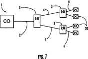
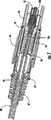
Für Erläuterungszwecke stellt
Wie am besten in
Das Kabel
Im Allgemeinen sind die meisten der Komponenten des Verbindungssteckers
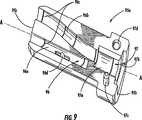
Wie in
Wie in
Der Kabelklemmabschnitt
Ebenso weist die Halbschale
Wie in
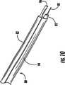
Die Ummantelung
Wie in
Ein Mittelabschnitt der Ummantelung
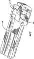
Nachdem der Wärmeschrumpfschlauch
Ein zweites Ende der Drahtanordnung
Das vorkonfektionierte Kabel
Die beschriebene erläuternde Ausführungsform schafft eine optische Verbindung, die vor Ort ohne irgendwelche Spezialwerkzeuge, eine Spezialausrüstung oder eine spezielle Übung hergestellt werden kann. Außerdem wird die optische Verbindung leicht verbunden oder getrennt, indem lediglich die Enden des vorkonfektionierten Kabels
Ein vorkonfektioniertes Kabel, das das Kabel
Insbesondere weist die Halbschale
Ebenso weist die Halbschale
Die vorkonfektionierten Kabel der vorliegenden Erfindung können auch mehr als einen optischen Wellenleiter abschließen. Mehrere optische Wellenleiter können locker angeordnet werden, in einem Band angeordnet werden oder gebündelt werden.
Ebenso kann eine Vielfalt von verschiedenen Kabeln bei der vorliegenden Erfindung verwendet werden.
Außerdem können die vorkonfektionierten Kabel gemäß der vorliegenden Erfindung auch elektrische Leistungskomponenten aufweisen, die durch den Verbindungsstecker verbunden und getrennt werden.
Viele Modifikationen und andere Ausführungsformen der vorliegenden Erfindung innerhalb des Schutzbereichs der beigefügten Ansprüche werden für den Fachmann ersichtlich. Außerdem kann die vorliegende Erfindung andere geeignete Konfigurationen, Hybridkonstruktionen, -strukturen und/oder eine Hybridausrüstung aufweisen. Daher ist die Erfindung selbstverständlich nicht auf die hierin offenbarten spezifischen Ausführungsformen begrenzt und Modifikationen und andere Ausführungsformen können innerhalb des Schutzbereichs der beigefügten Ansprüche durchgeführt werden. Obwohl spezifische Begriffe hierin verwendet werden, werden sie nur in einer allgemeinen und beschreibenden Hinsicht und nicht für Begrenzungszwecke verwendet. Die Erfindung wurde mit Bezug auf Abzweigkabel mit FTTx-Anwendungen beschrieben, aber die erfindungsgemäßen Konzepte der vorliegenden Erfindung sind auf andere geeignete Anwendungen anwendbar.Many modifications and other embodiments of the present invention within the scope of the appended claims will become apparent to those skilled in the art. In addition, the present invention may have other suitable configurations, hybrid constructions, structures, and / or hybrid equipment. Therefore, it should be understood that the invention is not limited to the specific embodiments disclosed herein, and modifications and other embodiments may be made within the scope of the appended claims. Although specific terms are used herein, they are used only in a general and descriptive sense and not for limitation. The invention has been described with reference to branch cables with FTTx Applications are described, but the inventive concepts of the present invention are applicable to other suitable applications.
ZITATE ENTHALTEN IN DER BESCHREIBUNG QUOTES INCLUDE IN THE DESCRIPTION
Diese Liste der vom Anmelder aufgeführten Dokumente wurde automatisiert erzeugt und ist ausschließlich zur besseren Information des Lesers aufgenommen. Die Liste ist nicht Bestandteil der deutschen Patent- bzw. Gebrauchsmusteranmeldung. Das DPMA übernimmt keinerlei Haftung für etwaige Fehler oder Auslassungen.This list of the documents listed by the applicant has been generated automatically and is included solely for the better information of the reader. The list is not part of the German patent or utility model application. The DPMA assumes no liability for any errors or omissions.
Zitierte PatentliteraturCited patent literature
- US 10/294136[0001]
US 10/294136[0001] - US 6714710[0001]US 6714710[0001]
- US 09/645916[0001]US 09/645916[0001]
- US 6542674[0001, 0034]US 6542674[0001, 0034]
- US 10/659666[0001]
US 10/659666[0001] - US 09/967259[0001]US 09/967259[0001]
- US 6648520[0001]US 6648520[0001]
- US 10/383468[0001]
US 10/383468[0001] - US 6785450[0001]US 6785450[0001]
- US 09/579555[0001]US 09/579555[0001]
- US 6546175[0001]US 6546175[0001]
- US 6256438[0058]US 6256438[0058]
- US 6356690[0058]US 6356690[0058]
- US 6621964[0059]US 6621964[0059]
- US 6618526[0059]US 6618526[0059]
Claims (15)
Translated fromGermanApplications Claiming Priority (4)
| Application Number | Priority Date | Filing Date | Title |
|---|---|---|---|
| GB0515888AGB2428937B (en) | 2005-08-01 | 2005-08-01 | Self-configuring cellular basestation |
| GB0515888.6 | 2005-08-01 | ||
| GB0610650.4 | 2006-05-30 | ||
| GB0610650AGB2428942B (en) | 2005-08-01 | 2006-05-30 | Local area cellular basestation |
Publications (1)
| Publication Number | Publication Date |
|---|---|
| DE202005021930U1true DE202005021930U1 (en) | 2011-08-08 |
Family
ID=34983951
Family Applications (5)
| Application Number | Title | Priority Date | Filing Date |
|---|---|---|---|
| DE200520021930Expired - LifetimeDE202005021930U1 (en) | 2005-08-01 | 2005-03-30 | Fiber optic decoupling cables and pre-connected assemblies with toning parts |
| DE200620020958Expired - LifetimeDE202006020958U1 (en) | 2005-08-01 | 2006-07-28 | Self-configuring cellular base station |
| DE200620020961Expired - LifetimeDE202006020961U1 (en) | 2005-08-01 | 2006-07-28 | Access point for mobile communication network |
| DE200620020960Expired - LifetimeDE202006020960U1 (en) | 2005-08-01 | 2006-07-28 | Handover within a mobile network |
| DE200620020957Expired - LifetimeDE202006020957U1 (en) | 2005-08-01 | 2006-07-28 | Self-configuring cellular base station |
Family Applications After (4)
| Application Number | Title | Priority Date | Filing Date |
|---|---|---|---|
| DE200620020958Expired - LifetimeDE202006020958U1 (en) | 2005-08-01 | 2006-07-28 | Self-configuring cellular base station |
| DE200620020961Expired - LifetimeDE202006020961U1 (en) | 2005-08-01 | 2006-07-28 | Access point for mobile communication network |
| DE200620020960Expired - LifetimeDE202006020960U1 (en) | 2005-08-01 | 2006-07-28 | Handover within a mobile network |
| DE200620020957Expired - LifetimeDE202006020957U1 (en) | 2005-08-01 | 2006-07-28 | Self-configuring cellular base station |
Country Status (9)
| Country | Link |
|---|---|
| US (13) | US8204543B2 (en) |
| EP (9) | EP2375798B1 (en) |
| JP (9) | JP5021644B2 (en) |
| CN (8) | CN101278590B (en) |
| DE (5) | DE202005021930U1 (en) |
| ES (2) | ES2411133T3 (en) |
| GB (10) | GB2432082B (en) |
| PL (2) | PL2337393T3 (en) |
| WO (1) | WO2007015066A2 (en) |
Cited By (5)
| Publication number | Priority date | Publication date | Assignee | Title |
|---|---|---|---|---|
| DE102014011082A1 (en)* | 2014-07-30 | 2016-02-04 | Airbus Ds Gmbh | Protective device for an elongate hollow body |
| USD771569S1 (en) | 2016-02-12 | 2016-11-15 | Bridgeport Fittings, Inc. | Electrical connector with cable armor stop |
| USD815604S1 (en) | 2016-02-12 | 2018-04-17 | Bridgeport Fittings, Inc. | Cable armor stop |
| US10367344B2 (en) | 2016-03-02 | 2019-07-30 | Bridgeport Fittings, Incorporated | Cable armor stop |
| DE102019118733B3 (en) | 2019-07-10 | 2020-06-18 | Md Elektronik Gmbh | Connection connection with a hybrid cable arrangement and a circuit board arrangement |
Families Citing this family (401)
| Publication number | Priority date | Publication date | Assignee | Title |
|---|---|---|---|---|
| AU2000258144A1 (en)* | 2000-06-14 | 2001-12-24 | Nokia Corporation | Method and system for performing a location registration |
| US7308263B2 (en) | 2001-02-26 | 2007-12-11 | Kineto Wireless, Inc. | Apparatus for supporting the handover of a telecommunication session between a licensed wireless system and an unlicensed wireless system |
| US7349698B2 (en) | 2002-10-18 | 2008-03-25 | Kineto Wireless, Inc. | Registration messaging in an unlicensed mobile access telecommunications system |
| US7369859B2 (en) | 2003-10-17 | 2008-05-06 | Kineto Wireless, Inc. | Method and system for determining the location of an unlicensed mobile access subscriber |
| KR20070044072A (en)* | 2002-10-18 | 2007-04-26 | 키네토 와이어리즈 인코포레이션 | Apparatus and method for extending coverage area of licensed wireless communication system using unlicensed wireless communication system |
| US7885644B2 (en) | 2002-10-18 | 2011-02-08 | Kineto Wireless, Inc. | Method and system of providing landline equivalent location information over an integrated communication system |
| US7640008B2 (en) | 2002-10-18 | 2009-12-29 | Kineto Wireless, Inc. | Apparatus and method for extending the coverage area of a licensed wireless communication system using an unlicensed wireless communication system |
| US7606190B2 (en) | 2002-10-18 | 2009-10-20 | Kineto Wireless, Inc. | Apparatus and messages for interworking between unlicensed access network and GPRS network for data services |
| WO2004075582A1 (en)* | 2003-02-21 | 2004-09-02 | Nortel Networks Limited | Data communication apparatus and method for establishing a codec-bypass connection |
| US8027265B2 (en) | 2004-03-19 | 2011-09-27 | Genband Us Llc | Providing a capability list of a predefined format in a communications network |
| WO2005089055A2 (en)* | 2004-03-19 | 2005-09-29 | Nortel Networks Limited | Communicating processing capabilites along a communications path |
| US8437307B2 (en)* | 2007-09-03 | 2013-05-07 | Damaka, Inc. | Device and method for maintaining a communication session during a network transition |
| US7940746B2 (en) | 2004-08-24 | 2011-05-10 | Comcast Cable Holdings, Llc | Method and system for locating a voice over internet protocol (VoIP) device connected to a network |
| EP1827034B1 (en)* | 2004-12-17 | 2009-03-11 | Huawei Technologies Co., Ltd. | A method and system of holding session continuity |
| ATE520276T1 (en)* | 2005-04-26 | 2011-08-15 | Vodafone Plc | FAST USER LEVEL BUILDING IN A TELECOMMUNICATIONS NETWORK |
| US8483173B2 (en) | 2005-05-31 | 2013-07-09 | Genband Us Llc | Methods and systems for unlicensed mobile access realization in a media gateway |
| DE202005021930U1 (en)* | 2005-08-01 | 2011-08-08 | Corning Cable Systems Llc | Fiber optic decoupling cables and pre-connected assemblies with toning parts |
| US7792150B2 (en) | 2005-08-19 | 2010-09-07 | Genband Us Llc | Methods, systems, and computer program products for supporting transcoder-free operation in media gateway |
| EP1932385B1 (en) | 2005-10-04 | 2013-05-01 | Telefonaktiebolaget L M Ericsson (publ) | Access control in radio access network having pico base stations |
| EP1798998B1 (en) | 2005-12-14 | 2011-06-15 | Research In Motion Limited | Method and apparatus for user equipment directed radio resource control in a UMTS network |
| US7835346B2 (en)* | 2006-01-17 | 2010-11-16 | Genband Us Llc | Methods, systems, and computer program products for providing transcoder free operation (TrFO) and interworking between unlicensed mobile access (UMA) and universal mobile telecommunications system (UMTS) call legs using a media gateway |
| WO2007085175A1 (en)* | 2006-01-24 | 2007-08-02 | Huawei Technologies Co., Ltd. | Authentication method, system and authentication center based on end to end communication in the mobile network |
| EP1835686B1 (en)* | 2006-03-13 | 2015-12-23 | Vodafone Group PLC | Method of providing access to an IP multimedia subsystem based on provided access network data. |
| US8832449B2 (en)* | 2006-03-22 | 2014-09-09 | Lg Electronics Inc. | Security considerations for the LTE of UMTS |
| US8165086B2 (en) | 2006-04-18 | 2012-04-24 | Kineto Wireless, Inc. | Method of providing improved integrated communication system data service |
| US7613444B2 (en) | 2006-04-28 | 2009-11-03 | Telefonaktiebolaget Lm Ericsson (Publ) | Dynamic building of monitored set |
| DE602006017517D1 (en) | 2006-05-17 | 2010-11-25 | Research In Motion Ltd | Method and system for indicating a cause for a degradation of a signaling connection in a UMTS network |
| US8817696B2 (en)* | 2006-05-22 | 2014-08-26 | Cisco Technology, Inc. | Enhanced unlicensed mobile access network architecture |
| DK2667660T3 (en)* | 2006-06-20 | 2017-08-07 | Interdigital Tech Corp | Recovery from a failed handover in an LTE system |
| US20080039086A1 (en) | 2006-07-14 | 2008-02-14 | Gallagher Michael D | Generic Access to the Iu Interface |
| US7852817B2 (en) | 2006-07-14 | 2010-12-14 | Kineto Wireless, Inc. | Generic access to the Iu interface |
| US20080076425A1 (en) | 2006-09-22 | 2008-03-27 | Amit Khetawat | Method and apparatus for resource management |
| US7912004B2 (en) | 2006-07-14 | 2011-03-22 | Kineto Wireless, Inc. | Generic access to the Iu interface |
| US7606202B2 (en)* | 2006-07-28 | 2009-10-20 | Tekelec | Methods, systems, and computer program products for offloading call control services from a first network of a first type to a second network of a second type |
| US20080031214A1 (en)* | 2006-08-07 | 2008-02-07 | Mark Grayson | GSM access point realization using a UMA proxy |
| US20080039141A1 (en)* | 2006-08-10 | 2008-02-14 | Holger Claussen | Changing the scrambling code of a base station for wireless telecommunications |
| GB2441375B (en)* | 2006-08-29 | 2011-03-02 | Ubiquisys Ltd | Basestation for cellular communication system |
| US8204502B2 (en) | 2006-09-22 | 2012-06-19 | Kineto Wireless, Inc. | Method and apparatus for user equipment registration |
| US20080076419A1 (en)* | 2006-09-22 | 2008-03-27 | Amit Khetawat | Method and apparatus for discovery |
| US7995994B2 (en) | 2006-09-22 | 2011-08-09 | Kineto Wireless, Inc. | Method and apparatus for preventing theft of service in a communication system |
| US20080076412A1 (en)* | 2006-09-22 | 2008-03-27 | Amit Khetawat | Method and apparatus for registering an access point |
| US8073428B2 (en) | 2006-09-22 | 2011-12-06 | Kineto Wireless, Inc. | Method and apparatus for securing communication between an access point and a network controller |
| US8036664B2 (en) | 2006-09-22 | 2011-10-11 | Kineto Wireless, Inc. | Method and apparatus for determining rove-out |
| US8301780B2 (en)* | 2006-09-26 | 2012-10-30 | Nextel Communications, Inc. | Client-based solution for seamless access to applications across networks |
| US8301734B1 (en)* | 2006-09-26 | 2012-10-30 | Nextel Communications, Inc. | Client-based solution for seamless access to applications across networks |
| JP4819638B2 (en)* | 2006-10-03 | 2011-11-24 | 株式会社エヌ・ティ・ティ・ドコモ | Communication control system |
| WO2008042414A2 (en)* | 2006-10-03 | 2008-04-10 | Interdigital Technology Corporation | Enhanced node b configuration with a universal integrated circuit card |
| US7813730B2 (en)* | 2006-10-17 | 2010-10-12 | Mavenir Systems, Inc. | Providing mobile core services independent of a mobile device |
| US8887235B2 (en)* | 2006-10-17 | 2014-11-11 | Mavenir Systems, Inc. | Authentication interworking |
| ATE551853T1 (en)* | 2006-10-19 | 2012-04-15 | Vodafone Plc | CONTROLLING THE USE OF ACCESS POINTS IN A TELECOMMUNICATIONS NETWORK |
| TWI533738B (en)* | 2006-10-20 | 2016-05-11 | 內數位科技公司 | Method and apparatus for self configuration of lte e-node bs |
| US9301155B2 (en) | 2006-10-23 | 2016-03-29 | T-Mobile Usa, Inc. | System and method for managing access point functionality and configuration |
| CN100591043C (en) | 2006-10-25 | 2010-02-17 | 华为技术有限公司 | System, access point, gateway and method for accessing network in different devices |
| PL2087634T3 (en)* | 2006-11-01 | 2017-01-31 | ERICSSON TELEFON AB L M (publ) | Telecommunication systems and encryption of control messages in such systems |
| FR2909822B1 (en)* | 2006-12-06 | 2010-04-30 | Radiotelephone Sfr | METHOD AND SYSTEM FOR CONTROLLING THE ESTABLISHMENT OF COMMUNICATION CHANNELS TO ENABLE THE TRANSMISSION OF MULTIMEDIA INFORMATION. |
| KR101315304B1 (en)* | 2006-12-08 | 2013-10-04 | 삼성전자주식회사 | Automatic installation system of Ubicell base station and its method |
| US7769009B1 (en)* | 2006-12-11 | 2010-08-03 | Sprint Communications Company L.P. | Automatic peer to peer mobile device data replication |
| US9008081B2 (en)* | 2006-12-14 | 2015-04-14 | Rpx Clearinghouse Llc | Serving gateway proxies for non-SIP speakers in a next generation network |
| US9131526B2 (en)* | 2012-05-31 | 2015-09-08 | Telefonaktiebolaget L M Ericsson (Publ) | Pooled transport and control functions in a 3GPP LTE network |
| TWI493952B (en) | 2006-12-27 | 2015-07-21 | Signal Trust For Wireless Innovation | Method and apparatus for base station self-configuration |
| US8688986B2 (en)* | 2006-12-27 | 2014-04-01 | Intel Corporation | Method for exchanging strong encryption keys between devices using alternate input methods in wireless personal area networks (WPAN) |
| CN101647232A (en)* | 2006-12-28 | 2010-02-10 | 艾利森电话股份有限公司 | Method in a network node for separating circuit switched and packet switched traffic |
| US8346239B2 (en) | 2006-12-28 | 2013-01-01 | Genband Us Llc | Methods, systems, and computer program products for silence insertion descriptor (SID) conversion |
| GB2446738C (en)* | 2007-02-02 | 2014-10-01 | Ubiquisys Ltd | Basestation measurement modes |
| GB2447439B (en)* | 2007-02-02 | 2012-01-25 | Ubiquisys Ltd | Access point power control |
| AU2008216739B2 (en)* | 2007-02-12 | 2011-09-15 | Interdigital Technology Corporation | Method and apparatus for supporting handoff from GPRS/GERAN to LTE EUTRAN |
| JP4364248B2 (en) | 2007-02-14 | 2009-11-11 | 株式会社東芝 | Communication system, gateway device and adapter device |
| US8073127B2 (en)* | 2007-02-21 | 2011-12-06 | Tekelec | Methods, systems, and computer program products for using a location routing number based query and response mechanism to effect subscriber cutover |
| US20080198996A1 (en)* | 2007-02-21 | 2008-08-21 | Tekelec | Methods, systems, and computer program products for using a location routing number based query and response mechanism to effect advanced routing |
| US8213440B2 (en) | 2007-02-21 | 2012-07-03 | Tekelec Global, Inc. | Methods, systems, and computer program products for using a location routing number based query and response mechanism to route calls to IP multimedia subsystem (IMS) subscribers |
| GB2449532B (en) | 2007-02-23 | 2009-05-27 | Ubiquisys Ltd | Basestation for cellular communications system |
| US8019331B2 (en) | 2007-02-26 | 2011-09-13 | Kineto Wireless, Inc. | Femtocell integration into the macro network |
| US7899024B2 (en)* | 2007-02-28 | 2011-03-01 | Intel Corporation | Method and apparatus to support VoIP calls in an IEEE 802.16 interface |
| US9350716B2 (en) | 2007-03-20 | 2016-05-24 | At&T Intellectual Property I, Lp | System and method for authentication of a communication device |
| US20080235778A1 (en)* | 2007-03-21 | 2008-09-25 | Motorola, Inc. | Communication network, an access network element and a method of operation therefor |
| US8498654B2 (en) | 2007-03-23 | 2013-07-30 | At&T Intellectual Property I, L.P. | Method and system for location-based communication |
| US8400989B2 (en)* | 2007-04-13 | 2013-03-19 | Airvana Llc | Activating private access points for wireless networking |
| DE602007013701D1 (en)* | 2007-04-17 | 2011-05-19 | Alcatel Lucent | Method for coupling a femto cell device to a mobile core network |
| WO2008130708A1 (en)* | 2007-04-20 | 2008-10-30 | Tekelec | Methods, systems, and computer program products for providing fault-tolerant service interaction and mediation function in a communications network |
| CN101309500B (en)* | 2007-05-15 | 2011-07-20 | 华为技术有限公司 | Method and device for security negotiation when switching between different wireless access technologies |
| US8483719B2 (en) | 2007-06-01 | 2013-07-09 | Qualcomm Incorporated | Methods and apparatus for determining FEMTO base station location |
| CN101321383B (en)* | 2007-06-05 | 2012-07-11 | 华为技术有限公司 | Communication system and method, home base station gateway and home user server |
| US20090019212A1 (en)* | 2007-07-12 | 2009-01-15 | Color City Enterprise Co., Ltd. | Flash disk of phone book |
| US20090016246A1 (en)* | 2007-07-12 | 2009-01-15 | Motorola, Inc. | Method and apparatus for data transmission in an unlicensed mobile access network |
| WO2009012187A2 (en)* | 2007-07-14 | 2009-01-22 | Tatara Systems, Inc. | Method and apparatus for supporting sip/ims-based femtocells |
| US8335299B1 (en)* | 2007-08-03 | 2012-12-18 | Computer Telephony Solutions, Inc. | System and method for capturing, sharing, annotating, archiving, and reviewing phone calls with related computer video in a computer document format |
| CN101836474B (en)* | 2007-08-17 | 2015-04-29 | 美国博通公司 | Self-configuring small scale base station |
| US9838911B1 (en)* | 2007-08-20 | 2017-12-05 | Fortinet, Inc. | Multitier wireless data distribution |
| EP2191669A4 (en)* | 2007-08-21 | 2016-11-16 | Unwired Planet Internat Ltd | A multi carrier frequency assignment method |
| DE202008018538U1 (en) | 2007-09-17 | 2015-06-30 | Telefonaktiebolaget L M Ericsson (Publ) | Arrangement in a telecommunication system |
| CN101394662B (en)* | 2007-09-21 | 2012-06-06 | 中兴通讯股份有限公司 | user authentication and access control method and system |
| DE102007045408A1 (en)* | 2007-09-21 | 2009-05-20 | T-Mobile International Ag | A method for the terminal-based detection of home base stations in a cellular mobile radio system by means of support by the mobile radio network |
| JP5068126B2 (en)* | 2007-09-25 | 2012-11-07 | 株式会社日立国際電気 | Wireless communication device |
| CN101400091B (en)* | 2007-09-30 | 2012-02-15 | 华为技术有限公司 | Method, system and device for conversion of session control signaling |
| CN101816202B (en) | 2007-10-01 | 2015-01-07 | 日本电气株式会社 | Wireless communication system, wireless communication method, base station, mobile station, base station control method, mobile station control method, and control program |
| CN101816206B (en)* | 2007-10-04 | 2014-10-08 | Lm爱立信电话有限公司 | Inter-system handoff using circuit switched bearers for serving general packet radio service support nodes |
| US8230035B2 (en)* | 2007-10-04 | 2012-07-24 | Alcatel Lucent | Method for authenticating mobile units attached to a femtocell that operates according to code division multiple access |
| US8428554B2 (en)* | 2007-10-04 | 2013-04-23 | Alcatel Lucent | Method for authenticating a mobile unit attached to a femtocell that operates according to code division multiple access |
| US8725191B2 (en) | 2007-10-09 | 2014-05-13 | Nec Corporation | Wireless communication system, wireless communication method, base station, control method of base station, and control program of base station |
| US7902691B2 (en)* | 2007-10-10 | 2011-03-08 | Tomtom International B.V. | Enhanced cigarette lighter adapter |
| WO2009054205A1 (en) | 2007-10-22 | 2009-04-30 | Nec Corporation | Wireless communication system, base station, wireless resource management method and base station control program |
| CN103607793B (en)* | 2007-10-25 | 2017-08-25 | 思达伦特网络有限责任公司 | Interworking gateway for mobile node |
| GB2454649B (en)* | 2007-10-26 | 2012-05-30 | Ubiquisys Ltd | Cellular basestation |
| ATE553628T1 (en) | 2007-11-13 | 2012-04-15 | Research In Motion Ltd | METHOD AND APPARATUS FOR STATUS/MODE TRANSITIONS |
| US8103274B2 (en)* | 2007-11-15 | 2012-01-24 | Airwalk Communications, Inc. | System, method, and computer-readable medium for IP-femtocell provisioned radio access network |
| US8902867B2 (en) | 2007-11-16 | 2014-12-02 | Qualcomm Incorporated | Favoring access points in wireless communications |
| US9648493B2 (en)* | 2007-11-16 | 2017-05-09 | Qualcomm Incorporated | Using identifiers to establish communication |
| US9603062B2 (en) | 2007-11-16 | 2017-03-21 | Qualcomm Incorporated | Classifying access points using pilot identifiers |
| US8848656B2 (en) | 2007-11-16 | 2014-09-30 | Qualcomm Incorporated | Utilizing broadcast signals to convey restricted association information |
| US8737295B2 (en) | 2007-11-16 | 2014-05-27 | Qualcomm Incorporated | Sector identification using sector parameters signatures |
| US8855007B2 (en) | 2007-11-19 | 2014-10-07 | Qualcomm Incorporated | Configuring an identifier for an access point |
| JP4920564B2 (en)* | 2007-11-29 | 2012-04-18 | 株式会社日立製作所 | Packet communication network and user related information distribution control device |
| KR100909105B1 (en)* | 2007-11-30 | 2009-07-30 | 한국전자통신연구원 | Session Control Method in Wireless Communication System |
| JP2009159352A (en)* | 2007-12-27 | 2009-07-16 | Hitachi Communication Technologies Ltd | Mobile communication network |
| US20090207812A1 (en)* | 2008-01-07 | 2009-08-20 | Vivek Gupta | Dual radio handovers beween wimax and 3gpp |
| EP2079273A1 (en)* | 2008-01-11 | 2009-07-15 | British Telecommunications public limited company | Mobile communication access point |
| US9462020B2 (en)* | 2008-01-16 | 2016-10-04 | Qualcomm Incorporated | Intelligent client: multiple channel switching over a digital broadcast network |
| JP4717898B2 (en)* | 2008-01-24 | 2011-07-06 | 株式会社エヌ・ティ・ティ・ドコモ | Radio base station apparatus and radio base station apparatus network incorporation method |
| GB2457029A (en)* | 2008-01-30 | 2009-08-05 | Ip Access Ltd | Network element and method for routing data in a data communication system |
| FR2928236B1 (en)* | 2008-02-28 | 2010-02-19 | Neuf Cegetel | METHOD FOR MANAGING THE OPERATION OF A LOCAL EQUIPMENT CONNECTED TO A FIXED NETWORK AND ASSOCIATED WITH A CELLULAR NETWORK |
| US8249553B2 (en)* | 2008-03-04 | 2012-08-21 | Alcatel Lucent | System and method for securing a base station using SIM cards |
| US8971888B2 (en)* | 2008-03-21 | 2015-03-03 | Qualcomm Incorporated | Cell selection and reselection in deployments with home nodeBs |
| KR101607167B1 (en) | 2008-03-25 | 2016-03-29 | 노텔 네트웍스 리미티드 | Method for controlling interference in femto cell deployments |
| US8688158B2 (en) | 2008-03-26 | 2014-04-01 | Nec Corporation | Radio resource control method, radio station apparatus, recording medium storing radio station control program, and radio communication system |
| CN101965744B (en)* | 2008-03-26 | 2013-08-28 | 日本电气株式会社 | Wireless station device, method of controlling wireless resource, recording medium containing wireless station control program, and wireless communication system |
| WO2009122778A1 (en) | 2008-03-31 | 2009-10-08 | 日本電気株式会社 | Radio station device, radio resource control method, recording medium containing radio station control program, and radio communication system |
| GB2459434A (en) | 2008-03-31 | 2009-10-28 | Vodafone Plc | Configuration of access points in a telecommunications network |
| JP2009253431A (en)* | 2008-04-02 | 2009-10-29 | Alcatel-Lucent Usa Inc | METHOD FOR OFF-LOADING PS TRAFFIC IN UMTS FEMTO CELL SOLUTION HAVING Iu INTERFACE |
| JP5047038B2 (en)* | 2008-04-09 | 2012-10-10 | 株式会社エヌ・ティ・ティ・ドコモ | Location registration method, radio control station and exchange |
| GB2459107B (en)* | 2008-04-09 | 2012-11-14 | Ubiquisys Ltd | Access point |
| CN101562834B (en)* | 2008-04-16 | 2014-04-09 | 三星电子株式会社 | Method and system supporting macro base station to be switched over to household base station |
| US20090262702A1 (en)* | 2008-04-18 | 2009-10-22 | Amit Khetawat | Method and Apparatus for Direct Transfer of RANAP Messages in a Home Node B System |
| WO2009132246A2 (en)* | 2008-04-25 | 2009-10-29 | Interdigital Patent Holdings, Inc. | Multi-cell wtrus configured to perform mobility procedures and methods |
| EP2272274B1 (en) | 2008-04-29 | 2017-08-02 | Apple Inc. | Ubiquitous access to femto-connected network |
| CN102227150B (en) | 2008-04-30 | 2014-11-05 | 华为技术有限公司 | Resource processing method, communication system and mobility management network element |
| US8719420B2 (en) | 2008-05-13 | 2014-05-06 | At&T Mobility Ii Llc | Administration of access lists for femtocell service |
| US8863235B2 (en)* | 2008-05-13 | 2014-10-14 | At&T Mobility Ii Llc | Time-dependent white list generation |
| WO2009149133A2 (en) | 2008-06-02 | 2009-12-10 | Tekelec | Methods, systems, and computer readable media for providing next generation network (ngn)-based end user services to legacy subscribers in a communications network |
| US8488582B2 (en)* | 2008-06-12 | 2013-07-16 | Alcatel Lucent | Minimal GAN RTP packet length via multi-level header compression |
| GB2461845B (en)* | 2008-06-27 | 2012-05-16 | Ubiquisys Ltd | Scrambling code selection |
| WO2010009177A2 (en)* | 2008-07-14 | 2010-01-21 | Zte (Usa) Inc. | Idle and paging support for wireless communication systems with private cells |
| US8885635B2 (en)* | 2008-07-17 | 2014-11-11 | T-Mobile Usa, Inc. | System and method for selectively provisioning telecommunications services between an access point and a telecommunications network using a subscriber identifier |
| US8825876B2 (en)* | 2008-07-17 | 2014-09-02 | Qualcomm Incorporated | Apparatus and method for mobile virtual network operator (MVNO) hosting and pricing |
| US8619545B2 (en)* | 2008-07-17 | 2013-12-31 | T-Mobile Usa, Inc. | System and method for selectively provisioning telecommunications services between an access point and a telecommunications network based on landline telephone detection |
| US8953620B2 (en)* | 2008-07-17 | 2015-02-10 | T-Mobile Usa, Inc. | System and method for selectively provisioning telecommunications services between an access point and a telecommunications network using a subscriber identifier |
| US8989172B2 (en)* | 2008-07-22 | 2015-03-24 | Kyocera Corporation | Data routing through local network connected to a base station |
| KR101596828B1 (en)* | 2008-07-23 | 2016-02-23 | 엘지전자 주식회사 | How to configure random network autoconfiguration |
| US9237598B2 (en)* | 2008-07-23 | 2016-01-12 | Lg Electronics Inc. | Method for self-configuring a cellular infrastructure as desired, and a device therefor |
| GB2462803B (en)* | 2008-07-31 | 2012-10-24 | Ubiquisys Ltd | Establishing colocated second cell |
| US8462770B2 (en)* | 2008-08-04 | 2013-06-11 | Stoke, Inc. | Method and system for bypassing 3GPP packet switched core network when accessing internet from 3GPP UES using 3GPP radio access network |
| US20100027510A1 (en)* | 2008-08-04 | 2010-02-04 | Qualcomm Incorporated | Enhanced idle handoff to support femto cells |
| US8588773B2 (en) | 2008-08-04 | 2013-11-19 | Qualcomm Incorporated | System and method for cell search and selection in a wireless communication system |
| US8363665B2 (en)* | 2008-08-04 | 2013-01-29 | Stoke, Inc. | Method and system for bypassing 3GPP packet switched core network when accessing internet from 3GPP UEs using IP-BTS, femto cell, or LTE access network |
| CN101646205B (en)* | 2008-08-05 | 2014-07-09 | 华为技术有限公司 | Node, method and system for accessing mobile network to public network at high speed |
| JP5077133B2 (en) | 2008-08-07 | 2012-11-21 | 富士通株式会社 | Base station and data transfer method |
| CN101645824B (en)* | 2008-08-08 | 2012-04-18 | 华为技术有限公司 | Data transmission method, user terminal and network equipment |
| CA2734041A1 (en)* | 2008-08-12 | 2010-02-18 | Ntt Docomo, Inc. | Communication control system, communication system and communication control method |
| US8924960B2 (en)* | 2008-08-28 | 2014-12-30 | Intel Corporation | Assignment, at least in part, of at least one virtual machine to at least one packet |
| GB2463708B (en) | 2008-09-23 | 2012-11-14 | Ubiquisys Ltd | Basestation able to make measurements in additional networks |
| JP5245692B2 (en)* | 2008-09-29 | 2013-07-24 | 富士通株式会社 | Communication apparatus and connection method |
| WO2010039084A1 (en) | 2008-10-01 | 2010-04-08 | Telefonaktiebolaget L M Ericsson (Publ) | Method for enabling a home base station to choose between local and remote transportation of uplink data packets |
| WO2010039085A1 (en)* | 2008-10-01 | 2010-04-08 | Telefonaktiebolaget L M Ericsson (Publ) | Handling of local breakout traffic in a home base station |
| EP2332377B1 (en)* | 2008-10-02 | 2016-07-06 | Telefonaktiebolaget LM Ericsson (publ) | Area identifier replacement in a wireless communication network |
| WO2010048345A1 (en)* | 2008-10-21 | 2010-04-29 | Spidercloud Wireless | Packet routing methods and apparatus in a communication system |
| CN101374111B (en)* | 2008-10-22 | 2011-02-09 | 华为技术有限公司 | Method, device and system for sending PS services |
| US8188955B2 (en)* | 2008-10-27 | 2012-05-29 | Himax Technologies Limited | Source driving circuit with output buffer |
| WO2010050222A1 (en)* | 2008-10-30 | 2010-05-06 | パナソニック株式会社 | Base station device, gateway device, call connecting method, and wireless communication system |
| US9401855B2 (en)* | 2008-10-31 | 2016-07-26 | At&T Intellectual Property I, L.P. | Methods and apparatus to deliver media content across foreign networks |
| JP2012508533A (en) | 2008-11-10 | 2012-04-05 | リサーチ イン モーション リミテッド | Method and apparatus for transitioning to a battery efficient state or configuration by instructing termination of data transmission in long term evolution |
| GB2465402B8 (en)* | 2008-11-18 | 2014-07-23 | Ip Access Ltd | Method and apparatus for providing access to a packet data network |
| US8886164B2 (en) | 2008-11-26 | 2014-11-11 | Qualcomm Incorporated | Method and apparatus to perform secure registration of femto access points |
| CN102217388A (en)* | 2008-11-28 | 2011-10-12 | 松下电器产业株式会社 | Wireless communication base station device and total transmission power regulating method |
| WO2010061503A1 (en) | 2008-11-28 | 2010-06-03 | 日本電気株式会社 | Base station device, method for controlling base station device, communication system, and storage medium having program stored therein |
| WO2010064365A1 (en) | 2008-12-03 | 2010-06-10 | 日本電気株式会社 | Base station apparatus, method for controlling base station apparatus, processor unit, storage medium, and wireless communication system |
| US8848594B2 (en)* | 2008-12-10 | 2014-09-30 | Blackberry Limited | Method and apparatus for discovery of relay nodes |
| JP5212071B2 (en)* | 2008-12-15 | 2013-06-19 | 富士通株式会社 | Communication device and mobile terminal |
| US20100150022A1 (en)* | 2008-12-17 | 2010-06-17 | Research In Motion Corporation | System and Method for a Relay Protocol Stack |
| US8311061B2 (en) | 2008-12-17 | 2012-11-13 | Research In Motion Limited | System and method for multi-user multiplexing |
| JP2010147682A (en)* | 2008-12-17 | 2010-07-01 | Sharp Corp | Radio communication system and indoor base station |
| US8040904B2 (en)* | 2008-12-17 | 2011-10-18 | Research In Motion Limited | System and method for autonomous combining |
| JP2010147681A (en)* | 2008-12-17 | 2010-07-01 | Sharp Corp | Radio communication system and indoor base station |
| US8402334B2 (en) | 2008-12-17 | 2013-03-19 | Research In Motion Limited | System and method for hybrid automatic repeat request (HARQ) functionality in a relay node |
| US8446856B2 (en) | 2008-12-19 | 2013-05-21 | Research In Motion Limited | System and method for relay node selection |
| US8335466B2 (en) | 2008-12-19 | 2012-12-18 | Research In Motion Limited | System and method for resource allocation |
| US8265128B2 (en) | 2008-12-19 | 2012-09-11 | Research In Motion Limited | Multiple-input multiple-output (MIMO) with relay nodes |
| CN101772036B (en)* | 2008-12-31 | 2012-07-18 | 中兴通讯股份有限公司 | Physical area automatic identifier configuration method and device |
| JP5375836B2 (en) | 2009-01-09 | 2013-12-25 | 日本電気株式会社 | BASE STATION DEVICE, MOBILE STATION DEVICE, NOTIFICATION SYSTEM, BASE STATION DEVICE CONTROL METHOD, MOBILE STATION DEVICE CONTROL METHOD, AND PROGRAM |
| US8213401B2 (en)* | 2009-01-13 | 2012-07-03 | Adc Telecommunications, Inc. | Systems and methods for IP communication over a distributed antenna system transport |
| USRE47466E1 (en)* | 2009-01-13 | 2019-06-25 | Commscope Technologies Llc | Systems and methods for IP communication over a distributed antenna system transport |
| CN101478753B (en)* | 2009-01-16 | 2010-12-08 | 中兴通讯股份有限公司 | Security management method and system for IMS network access by WAPI terminal |
| US8548455B2 (en)* | 2009-01-16 | 2013-10-01 | Broadcom Corporation | Method and system for installation and configuration of a femtocell |
| CN101784055B (en)* | 2009-01-16 | 2015-06-10 | 中兴通讯股份有限公司 | Peripheral component interconnect (PCI) automatic distribution method and device |
| US8615258B2 (en) | 2009-01-22 | 2013-12-24 | Intel Mobile Communications GmbH | Home base station communication with a mobile radio communication device using a home base station group member identifier |
| FR2941585B1 (en)* | 2009-01-28 | 2013-04-12 | Plugnsurf | PORTABLE MULTI-NETWORK COMMUNICATION DEVICE |
| JP5291204B2 (en)* | 2009-02-12 | 2013-09-18 | エルジー エレクトロニクス インコーポレイティド | Communication method using femto base station type change |
| JP2010187275A (en)* | 2009-02-13 | 2010-08-26 | Nec Corp | Data transfer radio base station system, terminal device, terminal device with video photographing function, femto base station, video data processing method, and program |
| JP5422223B2 (en)* | 2009-02-23 | 2014-02-19 | 株式会社Nttドコモ | Mobile communication system and terminal user management method |
| US8320344B2 (en) | 2009-02-27 | 2012-11-27 | T-Mobile Usa, Inc. | System and method for provisioning telecommunications services between an access point and a telecommunications network and providing a missing information notification |
| US8484457B2 (en)* | 2009-03-10 | 2013-07-09 | T-Mobile Usa, Inc. | Method of securely pairing devices with an access point for an IP-based wireless network |
| TWI415424B (en)* | 2009-03-27 | 2013-11-11 | Mstar Semiconductor Inc | Wireless WAN to Ethernet conversion device and transmission system thereof |
| JP5517187B2 (en)* | 2009-04-10 | 2014-06-11 | 日本電気株式会社 | Femtocell base station, authentication device, communication system, control method, and program |
| JP5780574B2 (en) | 2009-04-17 | 2015-09-16 | 日本電気株式会社 | COMMUNICATION CONTROL DEVICE, COMMUNICATION SYSTEM, CONTROL METHOD, AND PROGRAM |
| US20100267386A1 (en)* | 2009-04-17 | 2010-10-21 | Qualcomm Incorporated | Methods and apparatus for facilitating handoff between a femtocell base station and a cellular base station |
| EP2425584B1 (en)* | 2009-04-30 | 2013-02-13 | Telefonaktiebolaget LM Ericsson (publ) | Core network node selection in a mobile communication network |
| KR101652442B1 (en)* | 2009-05-05 | 2016-08-30 | 엘지전자 주식회사 | server for control plane at mobile communication network and method for controlling establishment of connection thereof |
| JP5383307B2 (en)* | 2009-05-08 | 2014-01-08 | ソフトバンクBb株式会社 | Small base station, setting method |
| US8249604B2 (en)* | 2009-06-04 | 2012-08-21 | United States Cellular Corporation | System and method for landline replacement |
| JP5059228B2 (en)* | 2009-06-23 | 2012-10-24 | シャープ株式会社 | Mobile communication system, mobile station, location management device, subscriber information management device, first access control device, and communication method |
| JP4648469B2 (en)* | 2009-06-26 | 2011-03-09 | 株式会社エヌ・ティ・ティ・ドコモ | Mobile communication method, mobile station and radio base station |
| JP5392830B2 (en) | 2009-07-02 | 2014-01-22 | 日本電気株式会社 | Femtocell base station, communication system, method and apparatus program |
| JP5535536B2 (en) | 2009-07-02 | 2014-07-02 | 日本電気株式会社 | Femtocell base station, gateway system, MAP-GW apparatus, communication system, control method and program |
| GB2471681B (en) | 2009-07-07 | 2011-11-02 | Ubiquisys Ltd | Interference mitigation in a femtocell access point |
| JP5424314B2 (en) | 2009-07-21 | 2014-02-26 | 日本電気株式会社 | Femtocell base station, gateway system, MAPGW apparatus, communication system, method and apparatus program |
| CN101964975B (en)* | 2009-07-23 | 2015-07-22 | 中兴通讯股份有限公司 | Method and system for optimizing home NodeB (HNB) position area configuration |
| CN101990210B (en)* | 2009-07-31 | 2013-06-05 | 中兴通讯股份有限公司 | Distribution method of PCIs (Physical Cell Identities) in long-term evolution network |
| US8908541B2 (en) | 2009-08-04 | 2014-12-09 | Genband Us Llc | Methods, systems, and computer readable media for intelligent optimization of digital signal processor (DSP) resource utilization in a media gateway |
| US8743696B2 (en) | 2009-08-07 | 2014-06-03 | Cisco Technology, Inc. | Mobile transport solution for offloading to an alternate network |
| GB2472597B (en) | 2009-08-11 | 2012-05-16 | Ubiquisys Ltd | Power setting |
| US20110038304A1 (en)* | 2009-08-11 | 2011-02-17 | Yi-Neng Lin | Telecommunication network broadband off-loading system and method |
| US8638711B2 (en)* | 2009-08-11 | 2014-01-28 | Qualcomm Incorporated | Systems and methods of maintaining core network status during serving radio network subsystem relocation |
| US9125133B2 (en) | 2009-08-12 | 2015-09-01 | Qualcomm Incorporated | Method and apparatus for relay backhaul design in a wireless communication system |
| US9210622B2 (en)* | 2009-08-12 | 2015-12-08 | Qualcomm Incorporated | Method and apparatus for relay backhaul design in a wireless communication system |
| CN101998353A (en)* | 2009-08-20 | 2011-03-30 | 中兴通讯股份有限公司 | Bearer type indicating method, base station and system |
| GB2472866B (en)* | 2009-08-21 | 2013-05-08 | Samsung Electronics Co Ltd | Network elements, integrated circuits and methods for routing control |
| JP5580014B2 (en)* | 2009-09-18 | 2014-08-27 | ソフトバンクモバイル株式会社 | Communication service provision system |
| JP5343796B2 (en)* | 2009-09-30 | 2013-11-13 | 日本電気株式会社 | Authentication apparatus, femtocell system, and accounting method used therefor |
| US8224233B2 (en)* | 2009-10-09 | 2012-07-17 | At&T Mobility Ii Llc | Regulation of service in restricted telecommunication service area |
| US8510801B2 (en) | 2009-10-15 | 2013-08-13 | At&T Intellectual Property I, L.P. | Management of access to service in an access point |
| GB2474504B (en)* | 2009-10-19 | 2015-12-02 | Ubiquisys Ltd | Wireless access point |
| CN102045732B (en)* | 2009-10-19 | 2015-03-25 | 中兴通讯股份有限公司 | Physical cell identity planning method and device |
| GB2487176B (en)* | 2009-10-21 | 2014-04-23 | Toshiba Res Europ Ltd | Apparatus and method for use in a femto cell |
| US8498651B2 (en)* | 2009-11-06 | 2013-07-30 | Alcatel Lucent | Method of call admission control for home femtocells |
| CN102056272B (en)* | 2009-11-11 | 2013-09-11 | 中兴通讯股份有限公司 | Frequency search method and device |
| JP4927154B2 (en)* | 2009-11-11 | 2012-05-09 | 株式会社エヌ・ティ・ティ・ドコモ | Mobile communication system, home radio base station, and operating frequency determination method |
| US9015318B1 (en) | 2009-11-18 | 2015-04-21 | Cisco Technology, Inc. | System and method for inspecting domain name system flows in a network environment |
| US9009293B2 (en) | 2009-11-18 | 2015-04-14 | Cisco Technology, Inc. | System and method for reporting packet characteristics in a network environment |
| US9148380B2 (en)* | 2009-11-23 | 2015-09-29 | Cisco Technology, Inc. | System and method for providing a sequence numbering mechanism in a network environment |
| ES2805149T3 (en) | 2009-11-23 | 2021-02-10 | Blackberry Ltd | State or mode transition trigger based on the transmission of a connection release signaling indication message |
| WO2011061352A1 (en) | 2009-11-23 | 2011-05-26 | Research In Motion Limited | Method and apparatus for state/mode transitioning |
| BR112012012362B1 (en) | 2009-11-23 | 2021-05-18 | Blackberry Limited | method and apparatus for state/mode transition |
| CN102763485A (en)* | 2009-11-24 | 2012-10-31 | 捷讯研究有限公司 | Method and apparatus for state/mode transitioning |
| JP5441158B2 (en)* | 2009-11-25 | 2014-03-12 | 日本電気株式会社 | Management device, control device, communication system, control method, and program |
| CN102088749B (en)* | 2009-12-04 | 2013-05-15 | 中国移动通信集团公司 | A method and system for updating and switching terminal locations |
| US8792495B1 (en) | 2009-12-19 | 2014-07-29 | Cisco Technology, Inc. | System and method for managing out of order packets in a network environment |
| US8983532B2 (en) | 2009-12-30 | 2015-03-17 | Blackberry Limited | Method and system for a wireless communication device to adopt varied functionalities based on different communication systems by specific protocol messages |
| EP2523409A4 (en)* | 2010-01-04 | 2017-08-30 | Alcatel Lucent | Method and device for providing inter-domain service |
| JP5517199B2 (en) | 2010-01-19 | 2014-06-11 | 日本電気株式会社 | Broadcast distribution control apparatus, call state control apparatus, femtocell base station, communication system, method and apparatus program |
| CN102149190B (en)* | 2010-02-09 | 2014-01-22 | 华为技术有限公司 | Registration method and system of machine type communications (MTC) equipment |
| US8958838B2 (en)* | 2010-02-12 | 2015-02-17 | Qualcomm Incorporated | Multi-stage transmit power control scheme for access point |
| JP5288561B2 (en)* | 2010-02-26 | 2013-09-11 | Kddi株式会社 | Femtocell handoff method and system |
| CN102196438A (en) | 2010-03-16 | 2011-09-21 | 高通股份有限公司 | Communication terminal identifier management methods and device |
| US8885536B2 (en)* | 2010-04-13 | 2014-11-11 | Qualcomm Incorporated | Method and apparatus for managing local internet protocol offload |
| JP5440696B2 (en) | 2010-05-13 | 2014-03-12 | 日本電気株式会社 | Gateway device, base station, mobility management server, communication method |
| US9265073B2 (en)* | 2010-05-21 | 2016-02-16 | Kineto Wireless, Llc | System and method for dual mode communication |
| CN102291820B (en)* | 2010-06-17 | 2015-04-01 | 电信科学技术研究院 | Paging method, system and device |
| US8824433B2 (en)* | 2010-07-23 | 2014-09-02 | Verizon Patent And Licensing Inc. | Data offloading with distributed IP management and routing |
| US20130223369A1 (en)* | 2010-08-04 | 2013-08-29 | Deutsche Telekom Ag | Method, public land mobile network and user equipment |
| JP5697134B2 (en) | 2010-08-16 | 2015-04-08 | 日本電気株式会社 | COMMUNICATION SYSTEM, GATEWAY DEVICE, FEMTO CELL BASE STATION, COMMUNICATION METHOD AND DEVICE PROGRAM |
| US9426696B2 (en)* | 2010-08-24 | 2016-08-23 | Nokia Solutions And Networks Oy | Methods, apparatuses, system, related computer program product for handover procedures |
| US8737325B2 (en)* | 2010-09-01 | 2014-05-27 | ARGELA Yazilim be Bilişim Teknolojlleri San. ve Tic. A.Ş | Method and system for automatically managing operations of an IPTV located in a femtocell network |
| US20120108226A1 (en) | 2010-09-21 | 2012-05-03 | Htc Corporation | Method and apparatus for controlling timing of network performance logging in a wireless communication system |
| US8971814B2 (en) | 2010-09-28 | 2015-03-03 | Nec Corporation | Radio communication system, radio resource determination method therefor, communication management device, and control method and control program for communication management device |
| KR20120032644A (en)* | 2010-09-29 | 2012-04-06 | 주식회사 팬택 | Mobile terminal and control method using the same |
| US8787303B2 (en) | 2010-10-05 | 2014-07-22 | Cisco Technology, Inc. | Methods and apparatus for data traffic offloading at a router |
| US9344483B2 (en)* | 2010-10-13 | 2016-05-17 | Fujitsu Limited | System and method for facilitating remote downloading |
| US9112905B2 (en)* | 2010-10-22 | 2015-08-18 | Qualcomm Incorporated | Authentication of access terminal identities in roaming networks |
| JP5896177B2 (en) | 2010-10-22 | 2016-03-30 | 日本電気株式会社 | Wireless communication system, base station, management server, and wireless communication method |
| EP2636271A1 (en)* | 2010-11-03 | 2013-09-11 | Nokia Siemens Networks Oy | Apparatus and method for communication |
| EP2451214B1 (en)* | 2010-11-05 | 2012-11-28 | Alcatel Lucent | Method for deciding on a potential load balancing operation in a wireless network and corresponding network element |
| US8687727B2 (en)* | 2010-11-05 | 2014-04-01 | Intel Corporation | Coordinated multi-point transmission using interference feedback |
| US8831676B2 (en) | 2010-11-05 | 2014-09-09 | Blackberry Limited | Mobile communication device with subscriber identity module |
| EP2638636B1 (en)* | 2010-11-12 | 2019-10-16 | Alcatel Lucent | Reduction of interference in mobile telecommunications systems |
| US9179303B2 (en) | 2010-11-17 | 2015-11-03 | Qualcomm Incorporated | Methods and apparatus for transmitting and receiving secure and non-secure data |
| US8649359B2 (en) | 2010-11-19 | 2014-02-11 | Nokia Corporation | Apparatus and method for selection of a gateway of a local area network |
| JP2012118884A (en)* | 2010-12-02 | 2012-06-21 | Toshiba Corp | Processor and semiconductor device |
| US20120314692A1 (en)* | 2010-12-10 | 2012-12-13 | Qualcomm Incorporated | Method and apparatus for prioritizing femto node communications |
| GB2486716A (en)* | 2010-12-23 | 2012-06-27 | Ubiquisys Ltd | Short range wireless access device |
| US9003057B2 (en) | 2011-01-04 | 2015-04-07 | Cisco Technology, Inc. | System and method for exchanging information in a mobile wireless network environment |
| US8819757B2 (en)* | 2011-01-11 | 2014-08-26 | Manolo Fabio Rivera | Advanced wireless IPTV set top box |
| US9413395B2 (en) | 2011-01-13 | 2016-08-09 | Google Technology Holdings LLC | Inter-modulation distortion reduction in multi-mode wireless communication terminal |
| JP2012186701A (en)* | 2011-03-07 | 2012-09-27 | Ricoh Co Ltd | Radio communication terminal |
| US9668128B2 (en) | 2011-03-09 | 2017-05-30 | Qualcomm Incorporated | Method for authentication of a remote station using a secure element |
| CN102111794A (en)* | 2011-03-15 | 2011-06-29 | 西安新邮通信设备有限公司 | Concurrent processing method for on-hook process and changing-over across AN |
| CN103477668A (en)* | 2011-04-15 | 2013-12-25 | 诺基亚西门子网络公司 | Apparatus and method for communication |
| JP2012244477A (en)* | 2011-05-20 | 2012-12-10 | Sony Corp | Communication controller, communication control method, program, and communication system |
| US8948013B1 (en) | 2011-06-14 | 2015-02-03 | Cisco Technology, Inc. | Selective packet sequence acceleration in a network environment |
| US8737221B1 (en) | 2011-06-14 | 2014-05-27 | Cisco Technology, Inc. | Accelerated processing of aggregate data flows in a network environment |
| US8792353B1 (en) | 2011-06-14 | 2014-07-29 | Cisco Technology, Inc. | Preserving sequencing during selective packet acceleration in a network environment |
| US8743690B1 (en) | 2011-06-14 | 2014-06-03 | Cisco Technology, Inc. | Selective packet sequence acceleration in a network environment |
| US9130743B2 (en)* | 2011-06-21 | 2015-09-08 | Pyxim Wireless, Inc. | Method and apparatus for communicating between low message rate wireless devices and users via monitoring, control and information systems |
| JP5743206B2 (en) | 2011-06-23 | 2015-07-01 | 日本電気株式会社 | Service control apparatus, relay apparatus, femtocell base station, communication system, control method, and program |
| JP5589983B2 (en)* | 2011-07-21 | 2014-09-17 | 三菱電機株式会社 | access point |
| US8953803B2 (en)* | 2011-07-27 | 2015-02-10 | Telefonaktiebolaget Lm Ericsson (Publ) | Circuit switched mobile telephony in fixed wireless access |
| CN102917356B (en)* | 2011-08-03 | 2015-08-19 | 华为技术有限公司 | Subscriber equipment is accessed the method, apparatus and system of the packet core network of evolution |
| PL2557855T3 (en) | 2011-08-10 | 2018-06-29 | Alcatel Lucent | A sensor, a mobile user terminal and a method of a sensor sensing a mobile user terminal |
| EP2557870B1 (en)* | 2011-08-10 | 2020-07-08 | Alcatel Lucent | Configuring transmissions |
| JP5948762B2 (en)* | 2011-08-26 | 2016-07-06 | ソニー株式会社 | Information processing apparatus, communication system, and information processing apparatus control method |
| US9510256B2 (en)* | 2011-09-20 | 2016-11-29 | Wildfire.Exchange, Inc. | Seamless handoff, offload, and load balancing in integrated Wi-Fi/small cell systems |
| CN103096288B (en)* | 2011-11-02 | 2016-03-02 | 中磊电子(苏州)有限公司 | Use femto cell as the method for exchange |
| CN103096521A (en)* | 2011-11-07 | 2013-05-08 | 中怡(苏州)科技有限公司 | Method of integration of user equipment functions by using miniature base station |
| JP5345195B2 (en)* | 2011-11-07 | 2013-11-20 | 株式会社エヌ・ティ・ティ・ドコモ | Mobile station |
| WO2013068787A1 (en)* | 2011-11-10 | 2013-05-16 | Nokia Corporation | Method and apparatus to route packet flows over two transport radios |
| CA2823789C (en) | 2011-11-11 | 2016-08-16 | Research In Motion Limited | Method and apparatus for user equipment state transition |
| GB2497125A (en) | 2011-12-01 | 2013-06-05 | Nec Corp | Partial Network Monitor Mode Scanning for Multimode Home Node Bs |
| US9763080B2 (en) | 2011-12-23 | 2017-09-12 | Nokia Technologies Oy | Method and apparatus for selectively activating multiple subscriber identity modules |
| GB2498192A (en) | 2012-01-04 | 2013-07-10 | Ibm | Moving OSI layer 4 connections for UMTS network with data offload at celltower |
| US9220065B2 (en)* | 2012-01-16 | 2015-12-22 | Smith Micro Software, Inc. | Enabling a mobile broadband hotspot by an auxiliary radio |
| US10433161B2 (en)* | 2012-01-30 | 2019-10-01 | Telefonaktiebolaget Lm Ericsson (Publ) | Call handover between cellular communication system nodes that support different security contexts |
| WO2013123643A1 (en)* | 2012-02-21 | 2013-08-29 | Nokia Siemens Networks Oy | Signalling interfaces in communications |
| US20150030019A1 (en)* | 2012-03-26 | 2015-01-29 | Nokia Solutions And Networks Oy | Mobile switching center acting as a short message service gateway |
| KR101405678B1 (en) | 2012-04-16 | 2014-06-10 | 에스케이텔레시스 주식회사 | Handover system between heterogeneous networks |
| US20130310000A1 (en)* | 2012-05-15 | 2013-11-21 | Sunil Prasad | Communication systems and methods |
| US20130326131A1 (en)* | 2012-05-29 | 2013-12-05 | Texas Instruments Incorporated | Method for Security Context Switching and Management in a High Performance Security Accelerator System |
| JP6007604B2 (en)* | 2012-06-13 | 2016-10-12 | 日本電気株式会社 | Small wireless base station, charging system and charging method |
| US9265071B2 (en)* | 2012-07-10 | 2016-02-16 | Electronics And Telecommunications Research Institute | Signalling method for direct communication between terminals |
| CN103596254B (en)* | 2012-08-16 | 2017-02-22 | 京信通信系统(广州)有限公司 | Method for base-station self-configuration and base station |
| EP2713574B1 (en)* | 2012-09-26 | 2021-06-09 | Alcatel Lucent | Resilient packet data connectivity in a cellular network |
| CN103812723B (en)* | 2012-11-01 | 2017-03-01 | 财团法人工业技术研究院 | System, server and method for metering network access |
| TWI504291B (en)* | 2012-11-01 | 2015-10-11 | Ind Tech Res Inst | System, server and method for calculating data volume of network access |
| WO2014070198A1 (en)* | 2012-11-02 | 2014-05-08 | Nokia Corporation | Transferring an calls to an active device within a home cloud |
| WO2014092503A1 (en)* | 2012-12-13 | 2014-06-19 | Samsung Electronics Co., Ltd. | Method and apparatus for controlling devices in home network system |
| US9313730B2 (en)* | 2013-02-15 | 2016-04-12 | Blackberry Limited | Public land mobile network (“PLMN”) discovery communications in a wireless network |
| US9992021B1 (en) | 2013-03-14 | 2018-06-05 | GoTenna, Inc. | System and method for private and point-to-point communication between computing devices |
| CN110381477B (en)* | 2013-04-22 | 2022-08-26 | 瑞典爱立信有限公司 | Control of channel allocation for vehicle-to-vehicle communication by cellular network |
| MX354833B (en)* | 2013-04-29 | 2018-03-21 | Hughes Network Systems Llc | Data encryption protocols for mobile satellite communications. |
| JP2013158059A (en)* | 2013-05-20 | 2013-08-15 | Nec Corp | Communication system, femto cell base station, authentication device, communication method, and communication program |
| US9143292B2 (en)* | 2013-05-22 | 2015-09-22 | Telefonaktiebolaget L M Ericsson (Publ) | Method and apparatus for controlling a signal path of a radio communication |
| WO2015009915A2 (en)* | 2013-07-19 | 2015-01-22 | AppCard, Inc. | Methods and apparatus for cellular-based identification of individuals within a vicinity |
| CN103476144B (en)* | 2013-08-23 | 2016-08-10 | 北京创毅讯联科技股份有限公司 | Intranet and user equipment registration method based on Intranet |
| EP2846586B1 (en)* | 2013-09-06 | 2018-11-28 | Fujitsu Limited | A method of accessing a network securely from a personal device, a corporate server and an access point |
| US9532398B2 (en)* | 2013-09-11 | 2016-12-27 | Star Solutions International Inc. | Portable cellular network system |
| WO2015047234A1 (en)* | 2013-09-25 | 2015-04-02 | Intel Corporation | Authenticated time-of-flight indoor positioning systems and methods |
| JP5892991B2 (en)* | 2013-11-05 | 2016-03-23 | 株式会社東芝 | Apparatus and method used in femtocells |
| WO2015088264A1 (en)* | 2013-12-11 | 2015-06-18 | 엘지전자 주식회사 | Method for performing, by terminal, random access procedure over network in which multiple communication systems interwork, and apparatus therefor |
| ES2689805T3 (en)* | 2013-12-17 | 2018-11-15 | Telefonica, S.A. | Method, system and software product for interworking between different wireless technologies |
| US9680737B2 (en)* | 2013-12-20 | 2017-06-13 | Vodafone Ip Licensing Limited | Telecommunications networks |
| US9693373B1 (en) | 2014-03-20 | 2017-06-27 | Sprint Communications Company L.P. | Media session transfer between communication networks |
| WO2015168920A1 (en)* | 2014-05-09 | 2015-11-12 | 华为技术有限公司 | Method for managing base station and base station |
| US9805201B2 (en) | 2014-06-23 | 2017-10-31 | Google Inc. | Trust agents |
| WO2015197121A1 (en)* | 2014-06-26 | 2015-12-30 | Nokia Solutions And Networks Oy | Offloading of a wireless node authentication with core network |
| JP2016012881A (en) | 2014-06-30 | 2016-01-21 | ソニー株式会社 | Apparatus, method and program |
| US9578567B1 (en) | 2014-08-26 | 2017-02-21 | Luminate Wireless, Inc. | Data center relocation methods and apparatus |
| US11324022B1 (en)* | 2014-10-06 | 2022-05-03 | Sprint Spectrum L.P. | Method and system for selecting a carrier on which to schedule communications of a type of bearer traffic |
| WO2016058161A1 (en) | 2014-10-16 | 2016-04-21 | Intel Corporation | Method, apparatus and system for using user equipment as small evolved nodeb for small cell |
| US9338133B1 (en)* | 2014-11-10 | 2016-05-10 | Sprint Communications Company L.P. | Locating optimum security gateway |
| WO2016074741A1 (en)* | 2014-11-14 | 2016-05-19 | Huawei Technologies Co., Ltd. | Network node, user device and methods thereof |
| WO2016082079A1 (en)* | 2014-11-24 | 2016-06-02 | 华为技术有限公司 | Communication system, base station and communication method |
| WO2016089267A1 (en)* | 2014-12-04 | 2016-06-09 | Telefonaktiebolaget Lm Ericsson (Publ) | Secure connections establishment |
| US9820289B1 (en) | 2014-12-18 | 2017-11-14 | Sprint Spectrum L.P. | Method and system for managing quantity of carriers in air interface connection based on type of content |
| US9967881B1 (en) | 2014-12-18 | 2018-05-08 | Sprint Spectrum L.P. | Management of data transmission over radio-link encompassing multiple component carriers |
| US9807766B1 (en) | 2015-01-30 | 2017-10-31 | Sprint Spectrum L.P. | Method and system for component carrier selection based on content type |
| US10069738B2 (en) | 2015-04-01 | 2018-09-04 | At&T Intellectual Property I, L.P. | One cellular radio to support multiple phone lines and data at a location |
| US9930641B2 (en)* | 2015-07-09 | 2018-03-27 | Honeywell International Inc. | Automated and adaptive channel selection algorithm based on least noise and least density of wireless sensors network in neighborhood |
| US10129057B2 (en) | 2015-07-14 | 2018-11-13 | At&T Intellectual Property I, L.P. | Apparatus and methods for inducing electromagnetic waves on a cable |
| US10320586B2 (en) | 2015-07-14 | 2019-06-11 | At&T Intellectual Property I, L.P. | Apparatus and methods for generating non-interfering electromagnetic waves on an insulated transmission medium |
| US9722318B2 (en) | 2015-07-14 | 2017-08-01 | At&T Intellectual Property I, L.P. | Method and apparatus for coupling an antenna to a device |
| US10341142B2 (en) | 2015-07-14 | 2019-07-02 | At&T Intellectual Property I, L.P. | Apparatus and methods for generating non-interfering electromagnetic waves on an uninsulated conductor |
| US10742243B2 (en) | 2015-07-14 | 2020-08-11 | At&T Intellectual Property I, L.P. | Method and apparatus for coupling an antenna to a device |
| US10033107B2 (en) | 2015-07-14 | 2018-07-24 | At&T Intellectual Property I, L.P. | Method and apparatus for coupling an antenna to a device |
| US10009430B2 (en) | 2015-08-27 | 2018-06-26 | Intel IP Corporation | Apparatus, system and method of fine timing measurement (FTM) |
| US9763046B2 (en) | 2015-08-27 | 2017-09-12 | Intel IP Corporation | Apparatus, system and method of Fine Timing Measurement (FTM) |
| CN105208599A (en)* | 2015-08-27 | 2015-12-30 | 北京邮电大学 | Method of load balancing between cellular network and wireless local area network |
| US11178287B1 (en) | 2015-09-30 | 2021-11-16 | Sprint Spectrum L.P. | Use of a single channel for voice communications and multiple channels for non-voice communications |
| EP3360386B1 (en)* | 2015-10-08 | 2024-03-06 | Telefonaktiebolaget LM Ericsson (PUBL) | Transparent per-bearer switching between wwan and wlan |
| EP3412054B1 (en) | 2016-02-03 | 2024-04-03 | Commscope Technologies LLC | Priority based reconfiguration scheme for remote units |
| WO2017141268A1 (en)* | 2016-02-16 | 2017-08-24 | Rajah Vijay Kumar | Private system for mobile communication (psm) and apparatus therefor |
| ES2862450T3 (en)* | 2016-02-29 | 2021-10-07 | Commscope Technologies Llc | Automatic power configuration for a point-to-multipoint distributed radio access network |
| US10045359B1 (en) | 2016-03-08 | 2018-08-07 | Sprint Spectrum L.P. | Method and system for managing carriers based on simultaneous voice and data communication |
| US10623951B2 (en) | 2016-03-09 | 2020-04-14 | Qualcomm Incorporated | WWAN-WLAN aggregation security |
| US9998970B2 (en)* | 2016-04-28 | 2018-06-12 | Samsung Electronics Co., Ltd. | Fast VoWiFi handoff using IKE v2 optimization |
| US10051525B1 (en) | 2016-06-28 | 2018-08-14 | Sprint Spectrum L.P. | Controlling relay-UE operation based on bearer content type |
| US10517021B2 (en) | 2016-06-30 | 2019-12-24 | Evolve Cellular Inc. | Long term evolution-primary WiFi (LTE-PW) |
| US11553561B2 (en)* | 2016-10-28 | 2023-01-10 | Apple Inc. | Protection of the UE identity during 802.1x carrier hotspot and wi-fi calling authentication |
| US10833876B2 (en)* | 2016-10-28 | 2020-11-10 | Apple Inc. | Protection of the UE identity during 802.1x carrier hotspot and Wi-Fi calling authentication |
| CA3045198C (en)* | 2016-11-28 | 2023-06-13 | Huawei Technologies Co., Ltd. | Auto-configuration method and apparatus, and base station |
| CN108235317B (en)* | 2016-12-21 | 2019-06-21 | 电信科学技术研究院有限公司 | Method and device for access control |
| WO2018163206A2 (en)* | 2017-03-07 | 2018-09-13 | Quantum Creo Technology Llp | An integrated smart energy monitoring and control device |
| CN107888403B (en)* | 2017-06-07 | 2020-05-29 | 大唐移动通信设备有限公司 | Data transmission method and device |
| US11297502B2 (en)* | 2017-09-08 | 2022-04-05 | Futurewei Technologies, Inc. | Method and device for negotiating security and integrity algorithms |
| US20190097968A1 (en)* | 2017-09-28 | 2019-03-28 | Unisys Corporation | Scip and ipsec over nat/pat routers |
| US11134418B2 (en)* | 2017-10-12 | 2021-09-28 | Telefonaktiebolaget Lm Ericsson (Publ) | Communication device, network node, radio network node and methods performed therein for handling communication in a communication network |
| CN111316233A (en) | 2017-10-30 | 2020-06-19 | 华为技术有限公司 | Method and device for acquiring UE security capabilities |
| US10355745B2 (en)* | 2017-11-09 | 2019-07-16 | At&T Intellectual Property I, L.P. | Guided wave communication system with interference mitigation and methods for use therewith |
| US10736114B2 (en)* | 2018-01-10 | 2020-08-04 | Charter Communications Operating, Llc | RF channel analysis and improved usage of wireless channels in a wireless network |
| FR3091132B1 (en)* | 2018-12-21 | 2020-12-25 | Air Lynx | Transportable device implementing a private mobile radiocommunication network infrastructure |
| FR3091133B1 (en)* | 2018-12-21 | 2020-12-25 | Air Lynx | Installation of a private mobile radio communication network, method of forming such an installation and associated computer program |
| FR3091130B1 (en)* | 2018-12-21 | 2020-12-25 | Air Lynx | Method of federating two systems each comprising a private mobile radiocommunication network infrastructure, associated computer program and federating two systems each comprising a private mobile radiocommunication network infrastructure |
| US11716694B2 (en) | 2019-01-31 | 2023-08-01 | Commscope Technologies Llc | Estimating and controlling transmit power of user equipment by a base station |
| US11223666B2 (en)* | 2019-04-08 | 2022-01-11 | Hughes Network Systems, Llc | Method and system of providing second generation (2G) voice services over Internet protocol |
| CN110475242B (en)* | 2019-07-03 | 2021-11-23 | 深圳市广和通无线通信软件有限公司 | LTE network registration method, device, storage medium and computer equipment |
| FR3102332B1 (en)* | 2019-10-18 | 2024-03-08 | Sagemcom Broadband Sas | Method of connecting a communication node and communication node. |
| US12185090B2 (en)* | 2020-06-24 | 2024-12-31 | Cable Television Laboratories, Inc. | Dynamic triggering of minimum periodic search timer |
| US11956628B2 (en)* | 2020-11-23 | 2024-04-09 | Cisco Technology, Inc. | Openroaming for private communication systems |
| CN113252293B (en)* | 2021-06-08 | 2021-10-01 | 中国空气动力研究与发展中心低速空气动力研究所 | Gas rectification structure inside box body |
| US11991533B2 (en)* | 2022-03-31 | 2024-05-21 | Rakuten Symphony Singapore Pte. Ltd. | Method of changing antenna configuration, apparatus, and computer readable medium |
| CN114585086B (en)* | 2022-05-05 | 2022-08-05 | 深圳小米通讯技术有限公司 | Call response method, device, terminal device and storage medium |
| US12302417B2 (en) | 2022-06-30 | 2025-05-13 | T-Mobile Usa, Inc. | Identification of fraudulent network data sessions |
| US20240049055A1 (en)* | 2022-08-05 | 2024-02-08 | Aviat U.S., Inc. | Distributed adaptive radio configuration |
| US12418850B2 (en) | 2022-08-26 | 2025-09-16 | T-Mobile Usa. Inc. | Disabling roaming in overlapping coverage areas of wireless telecommunications networks |
| US12225623B2 (en) | 2022-08-26 | 2025-02-11 | T-Mobile Usa, Inc. | Selective roaming in wireless telecommunications networks |
| WO2025004345A1 (en)* | 2023-06-30 | 2025-01-02 | 株式会社Nttドコモ | Network node, base station, and communication method |
Citations (8)
| Publication number | Priority date | Publication date | Assignee | Title |
|---|---|---|---|---|
| US6256438B1 (en) | 1999-10-29 | 2001-07-03 | Siecor Operations, Llc | Fiber optic drop cable |
| US6356690B1 (en) | 1999-10-20 | 2002-03-12 | Corning Cable Systems Llc | Self-supporting fiber optic cable |
| US6542674B1 (en) | 2000-08-25 | 2003-04-01 | Corning Cable Systems Llc | Fiber optic cables with strength members |
| US6546175B1 (en) | 2000-05-26 | 2003-04-08 | Corning Cable Systems Llc | Self-supporting fiber optic cable |
| US6618526B2 (en) | 2001-09-27 | 2003-09-09 | Corning Cable Systems Llc | Fiber optic cables |
| US6621964B2 (en) | 2001-05-21 | 2003-09-16 | Corning Cable Systems Llc | Non-stranded high strength fiber optic cable |
| US6648520B2 (en) | 2001-09-28 | 2003-11-18 | Corning Cable Systems Llc | Fiber optic plug |
| US20100294136A1 (en) | 2009-05-24 | 2010-11-25 | G.E.W. Corporation Limited | Toaster with mechanism for raising carriage above an ejection position |
Family Cites Families (218)
| Publication number | Priority date | Publication date | Assignee | Title |
|---|---|---|---|---|
| SE8702208D0 (en) | 1987-05-26 | 1987-05-26 | Nira Automotive Ab | THE NIRA TURBO CONTROL SYSTEM |
| GB2254971B (en)* | 1991-03-07 | 1994-12-21 | Ericsson Telefon Ab L M | Mobile radio communications stations |
| JP2653000B2 (en)* | 1991-04-24 | 1997-09-10 | 日本電気株式会社 | Mobile wireless communication system |
| US5343512A (en)* | 1992-03-27 | 1994-08-30 | Motorola, Inc. | Call setup method for use with a network having mobile end users |
| US5915219A (en)* | 1992-09-10 | 1999-06-22 | Nokia Telecommunications Oy | Cellular radio network divided into a primary network covering a selected operating area and at least one subsystem covering possibly overlapping area, with possibility of handoff and registration between primary network and subsystem |
| KR100304238B1 (en)* | 1993-07-16 | 2001-11-22 | 맨스 에케로프 | Method and apparatus for controlling transceiver operation in wireless communication system |
| US5410754A (en)* | 1993-07-22 | 1995-04-25 | Minute Makers, Inc. | Bi-directional wire-line to local area network interface and method |
| SE514018C2 (en) | 1993-09-23 | 2000-12-11 | Ericsson Telefon Ab L M | Method of registration in a cellular cellular radio system |
| WO1995031075A1 (en)* | 1994-05-06 | 1995-11-16 | Motorola, Inc. | System for selecting a communication channel |
| AUPM593694A0 (en)* | 1994-05-27 | 1994-06-23 | Curtin University Of Technology | Underground microcellular communications network |
| JP3014275B2 (en) | 1994-07-05 | 2000-02-28 | エヌ・ティ・ティ移動通信網株式会社 | Mobile communication system |
| US5551064A (en)* | 1994-07-27 | 1996-08-27 | Motorola, Inc. | Method and apparatus for communication unit frequency assignment |
| DE4442410A1 (en)* | 1994-11-29 | 1996-05-30 | Alcatel Mobile Comm Deutsch | Radio system for a closed user group |
| JP3063822B2 (en) | 1994-12-28 | 2000-07-12 | エヌ・ティ・ティ移動通信網株式会社 | Adjacent zone information automatic generation method |
| US5675629A (en)* | 1995-09-08 | 1997-10-07 | At&T | Cordless cellular system base station |
| US5911120A (en)* | 1995-09-08 | 1999-06-08 | At&T Wireless Services | Wireless communication system having mobile stations establish a communication link through the base station without using a landline or regional cellular network and without a call in progress |
| FI105740B (en) | 1995-09-29 | 2000-09-29 | Nokia Mobile Phones Ltd | office communication |
| US6473623B1 (en)* | 1996-04-18 | 2002-10-29 | At&T Wireless Services, Inc. | Method for self-calibration of a wireless communication system |
| GB2313260A (en)* | 1996-05-17 | 1997-11-19 | Motorola Ltd | Accessing a plurality of communication systems |
| FI103556B1 (en)* | 1996-06-26 | 1999-07-15 | Nokia Telecommunications Oy | Procedure for position management and search in a cellular radio system |
| DE19633925C2 (en)* | 1996-08-22 | 2000-11-23 | Siemens Ag | Mobile radio system and base transceiver station with integrated telephone device |
| US5884145A (en)* | 1996-08-28 | 1999-03-16 | Telefon Akmebolget Lm Ericsson | Method and system for autonomously allocating a cellular communications channel for communication between a cellular terminal and a telephone base station |
| US5794157A (en)* | 1996-08-28 | 1998-08-11 | Telefonaktiebolaget Lm Ericsson | Method and system for autonomously allocating transmit power levels for communication between a cellular terminal and a telephone base station |
| EP0934672B1 (en)* | 1996-10-23 | 2004-07-21 | Siemens Aktiengesellschaft | Location dependent mobile communication terminal log on method |
| JP3585333B2 (en)* | 1996-12-26 | 2004-11-04 | 松下電器産業株式会社 | CDMA base station device |
| US5910946A (en)* | 1997-01-13 | 1999-06-08 | Samsung Electronics Co., Ltd. | Wireless internet network architecture for voice and data communications |
| DE19708189C2 (en)* | 1997-02-28 | 2000-02-17 | Deutsche Telekom Mobil | Cordless non-public communication system compatible with a public mobile communication system |
| US6384940B1 (en)* | 1997-04-21 | 2002-05-07 | Murata Kikai Kabushiki Kaisha | Facsimile device utilizing process unit for electrophotographic device |
| US6101388A (en)* | 1997-07-24 | 2000-08-08 | Intel Corporation | Method for reducing registration traffic in a GSM system |
| US6414952B2 (en)* | 1997-08-28 | 2002-07-02 | Broadcom Homenetworking, Inc. | Virtual gateway system and method |
| US6421328B1 (en)* | 1997-09-04 | 2002-07-16 | Northern Telecom Limited | Neighborhood list assimilation for cell-based microsystem |
| FR2768893B1 (en)* | 1997-09-23 | 1999-12-17 | Alsthom Cge Alcatel | LINK INITIALIZATION PROCESS BETWEEN A MOBILE TERMINAL AND A DOMESTIC BASE STATION |
| US6141565A (en)* | 1997-11-13 | 2000-10-31 | Metawave Communications Corporation | Dynamic mobile parameter optimization |
| FR2771585B1 (en) | 1997-11-24 | 2000-01-28 | Nortel Matra Cellular | PRIVATE BASE STATION FOR MOBILE RADIOTELEPHONE |
| JP3634610B2 (en)* | 1998-01-27 | 2005-03-30 | 富士通株式会社 | Automatic call system |
| US6125280A (en)* | 1998-03-19 | 2000-09-26 | Lucent Technologies Inc. | Automatic neighbor identification in a cellular system |
| JP3116893B2 (en)* | 1998-03-26 | 2000-12-11 | 日本電気株式会社 | Cellular system |
| FI111204B (en)* | 1998-06-29 | 2003-06-13 | Nokia Corp | Procedure and mobile phone for configuring a base station |
| JP3241672B2 (en)* | 1998-07-31 | 2001-12-25 | 三菱電機株式会社 | Interference wave detection device and interference wave detection method |
| KR100268679B1 (en)* | 1998-07-31 | 2000-10-16 | 윤종용 | Method for prioritizing handoff requests in mobile communication system |
| FI107861B (en)* | 1998-08-28 | 2001-10-15 | Nokia Mobile Phones Ltd | Neighbor cell measurements for cell reselection |
| US7596378B1 (en)* | 1999-09-30 | 2009-09-29 | Qualcomm Incorporated | Idle mode handling in a hybrid GSM/CDMA network |
| US6539237B1 (en) | 1998-11-09 | 2003-03-25 | Cisco Technology, Inc. | Method and apparatus for integrated wireless communications in private and public network environments |
| US6842462B1 (en)* | 1998-12-18 | 2005-01-11 | Lucent Technologies Inc. | Wireless access of packet based networks |
| US6311059B1 (en)* | 1999-02-05 | 2001-10-30 | Nec Corporation | Mobile radio station |
| SE519347C2 (en)* | 1999-02-18 | 2003-02-18 | Ericsson Telefon Ab L M | Procedure and node for updating information of a subscriber belonging to a localized service area |
| EP1032236A1 (en)* | 1999-02-24 | 2000-08-30 | ICO Services Ltd. | Improved congestion control using access classes |
| WO2000051330A1 (en) | 1999-02-24 | 2000-08-31 | Telefonaktiebolaget Lm Ericsson (Publ) | Methods and systems for call routing and codec negotiation in hybrid voice/data/internet/wireless systems |
| US6856612B1 (en) | 1999-02-24 | 2005-02-15 | Telefonaktiebolaget Lm Ericsson (Publ) | Methods and systems for call routing and codec negotiation in hybrid voice/data/internet/wireless systems |
| US6729929B1 (en) | 1999-03-17 | 2004-05-04 | Cisco Systems, Inc. | Method and apparatus for controlling wireless networks |
| US7003297B2 (en)* | 1999-04-06 | 2006-02-21 | Telefonaktiebolaget Lm Ericsson (Publ) | Partial support of mobility between radio access networks |
| GB2350521B (en) | 1999-04-30 | 2001-07-11 | Nokia Corp | A gateway arrangement |
| US6466793B1 (en)* | 1999-05-28 | 2002-10-15 | Ericsson Inc. | Automatic frequency allocation (AFA) for wireless office systems sharing the spectrum with public systems |
| KR100398784B1 (en) | 1999-06-15 | 2003-09-19 | 가부시키가이샤 엔.티.티.도코모 | Information management method for cell search in mobile communications system, cell search method of mobile station, mobile communications system, mobile station, base station and control station |
| US6473413B1 (en)* | 1999-06-22 | 2002-10-29 | Institute For Information Industry | Method for inter-IP-domain roaming across wireless networks |
| US6542741B2 (en)* | 1999-07-01 | 2003-04-01 | Ericsson, Inc. | Method of establishing an adaptive public neighbor cell list for mobile stations of a private cellular system |
| US6751207B1 (en)* | 1999-07-27 | 2004-06-15 | Cellco Partnership | Tunnelling voice over the internet protocol in a cellular network |
| GB2355885A (en)* | 1999-07-30 | 2001-05-02 | Nokia Telecommunications Oy | Network access control |
| WO2001041487A1 (en)* | 1999-12-01 | 2001-06-07 | Robert Bosch Gmbh | Method for allocating transmission channels in a telecommunications network and subscriber station |
| JP2001197557A (en)* | 2000-01-07 | 2001-07-19 | Sharp Corp | Wireless communication system |
| GB0000528D0 (en) | 2000-01-11 | 2000-03-01 | Nokia Networks Oy | Location of a station in a telecommunications system |
| US6668167B2 (en)* | 2000-01-26 | 2003-12-23 | Mcdowell Mark | Method and apparatus for sharing mobile user event information between wireless networks and fixed IP networks |
| US6310294B1 (en)* | 2000-04-03 | 2001-10-30 | At&T Corp. | Vertical separation rack for cable management |
| AU2001244951A1 (en)* | 2000-04-05 | 2001-10-15 | Telefonaktiebolaget Lm Ericsson (Publ) | Telecommunications network integrating cellular, packet-switched, and voice-over-ip infrastructures |
| FI108769B (en)* | 2000-04-07 | 2002-03-15 | Nokia Corp | Connection of a connection point in wireless telecommunication system |
| AU2000244000A1 (en) | 2000-04-11 | 2001-10-23 | Nokia Corporation | Application of rtp and rtcp in the amr transport in voice over ip networks |
| US6993359B1 (en)* | 2000-04-28 | 2006-01-31 | Cisco Technology, Inc. | Method and apparatus for inter-cell handover in wireless networks using multiple protocols |
| US6907017B2 (en)* | 2000-05-22 | 2005-06-14 | The Regents Of The University Of California | Mobility management in wireless internet protocol networks |
| KR100342512B1 (en)* | 2000-05-24 | 2002-06-28 | 윤종용 | A method for public call service when call manager has down state in a private wireless network |
| KR100334558B1 (en)* | 2000-05-24 | 2002-05-03 | 윤종용 | Wire·wireless unified in-building communication method and system |
| ITTS20000003A1 (en)* | 2000-05-31 | 2001-12-01 | Telit Networks Spa | SELF PLANNER: AUTOMATIC FREQUENTIAL PLANNING FOR RADIO MOBILE SYSTEMS |
| FI111208B (en)* | 2000-06-30 | 2003-06-13 | Nokia Corp | Arrangement of data encryption in a wireless telecommunication system |
| US6711417B1 (en)* | 2000-08-16 | 2004-03-23 | Sprint Spectrum, L.P. | Interface using an ISH and a service manager |
| US7085260B2 (en)* | 2000-08-22 | 2006-08-01 | Lucent Technologies Inc. | Internet protocol based wireless call processing |
| US6901061B1 (en)* | 2000-09-05 | 2005-05-31 | Cisco Technology, Inc. | Handoff control in an enterprise division multiple access wireless system |
| US8996698B1 (en) | 2000-11-03 | 2015-03-31 | Truphone Limited | Cooperative network for mobile internet access |
| ATE294487T1 (en)* | 2000-11-17 | 2005-05-15 | Ericsson Telefon Ab L M | MOBILE COMMUNICATION NETWORK |
| US6850763B1 (en)* | 2000-11-22 | 2005-02-01 | Winphoria Networks, Inc. | System and method of servicing mobile communications with a proxy switch |
| US20050239453A1 (en)* | 2000-11-22 | 2005-10-27 | Vikberg Jari T | Mobile communication network |
| US6954790B2 (en)* | 2000-12-05 | 2005-10-11 | Interactive People Unplugged Ab | Network-based mobile workgroup system |
| US7039027B2 (en) | 2000-12-28 | 2006-05-02 | Symbol Technologies, Inc. | Automatic and seamless vertical roaming between wireless local area network (WLAN) and wireless wide area network (WWAN) while maintaining an active voice or streaming data connection: systems, methods and program products |
| US7046652B2 (en)* | 2001-01-09 | 2006-05-16 | Cisco Technology, Inc. | System and method of a stackable wireless internet protocol base station |
| JP2002218528A (en)* | 2001-01-15 | 2002-08-02 | Matsushita Electric Ind Co Ltd | Base station apparatus and base station apparatus synchronization method |
| DE60131572T2 (en) | 2001-02-06 | 2008-10-23 | Nokia Corp. | ACCESS SYSTEM FOR A CELLULAR NETWORK |
| US20030119490A1 (en)* | 2001-02-26 | 2003-06-26 | Jahangir Mohammed | Wireless communications handset for facilitating licensed and unlicensed wireless communications, and method of operation |
| US6965584B2 (en)* | 2001-02-27 | 2005-11-15 | Telcordia Technologies, Inc. | Dynamic forward assignment of internet protocol addresses in wireless networks |
| US6473030B1 (en) | 2001-02-28 | 2002-10-29 | Seiko Epson Corporation | Infrastructure-aiding for satellite navigation receiver and method |
| US7483989B2 (en)* | 2001-03-13 | 2009-01-27 | Telefonaktiebolaget Lm Ericsson (Publ) | Method and apparatus for establishing a protocol proxy for a mobile host terminal in a multimedia session |
| US6947405B2 (en)* | 2001-03-19 | 2005-09-20 | Telefonaktiebolaget Lm Ericsson (Publ) | Cellular system with cybercells |
| FR2823053B1 (en)* | 2001-03-30 | 2003-08-29 | Evolium Sas | METHOD FOR ESTABLISHING A LIST OF NEIGHBORING CELLS IN A MOBILE RADIO COMMUNICATION SYSTEM |
| US7039028B2 (en)* | 2001-04-04 | 2006-05-02 | Telcordia Technologies, Inc. | Packet distribution and selection in soft handoff for IP-based base stations among multiple subnets |
| US8315651B2 (en)* | 2001-05-03 | 2012-11-20 | Kyocera Corporation | Instant messaging to a mobile device |
| US8086855B2 (en)* | 2001-05-16 | 2011-12-27 | Flash Networks Ltd. | Access to PLMN networks for non-PLMN devices, and to issues arising in interfaces in general between PLMN and non-PLMN networks |
| JP3699013B2 (en) | 2001-05-31 | 2005-09-28 | Necアクセステクニカ株式会社 | Mobile radio base station system |
| US7483411B2 (en)* | 2001-06-04 | 2009-01-27 | Nec Corporation | Apparatus for public access mobility LAN and method of operation thereof |
| US7193985B1 (en)* | 2001-06-14 | 2007-03-20 | Utstarcom, Inc. | System and method for managing foreign agent selections in a mobile internet protocol network |
| CA2389047C (en)* | 2001-06-14 | 2009-02-03 | At&T Corp. | Broadband network with enterprise wireless communication system and method for residential and business environment |
| US7002995B2 (en)* | 2001-06-14 | 2006-02-21 | At&T Corp. | Broadband network with enterprise wireless communication system for residential and business environment |
| US7272121B2 (en)* | 2001-06-19 | 2007-09-18 | Telcordia Technologies, Inc. | Methods and apparatus for a modular wireless system |
| US6771934B2 (en)* | 2001-06-19 | 2004-08-03 | Telcordia Technologies, Inc. | Methods and systems for reducing interference across coverage cells |
| US20040148279A1 (en)* | 2001-06-20 | 2004-07-29 | Nir Peleg | Scalable distributed hierarchical cache |
| US6670234B2 (en)* | 2001-06-22 | 2003-12-30 | International Business Machines Corporation | Method of integrating volatile and non-volatile memory cells on the same substrate and a semiconductor memory device thereof |
| US20030021260A1 (en) | 2001-07-25 | 2003-01-30 | Daley Robert S. | System and method for frame selection in IP-based CDMA network |
| US20030032451A1 (en)* | 2001-08-10 | 2003-02-13 | Jianhong Hu | Architecture for converged broadband wireless communications |
| US7181212B2 (en) | 2001-08-21 | 2007-02-20 | Telefonaktiebolaget Lm Ericsson (Publ) | Method and apparatus for location area updating in cellular communications |
| US20030040306A1 (en)* | 2001-08-23 | 2003-02-27 | Hanma Kentaro | Wireless communication system |
| US20030147383A1 (en)* | 2001-09-26 | 2003-08-07 | Karen Capers | Object communication services software development system and methods |
| US7117015B2 (en)* | 2002-10-25 | 2006-10-03 | Intel Corporation, Inc | Internet base station |
| US7103040B2 (en)* | 2001-11-19 | 2006-09-05 | Telefonaktieboaget Lm Ericsson (Publ) | Method and apparatus for identifying a node for data communications using its geographical location |
| JP3870081B2 (en)* | 2001-12-19 | 2007-01-17 | キヤノン株式会社 | COMMUNICATION SYSTEM AND SERVER DEVICE, CONTROL METHOD, COMPUTER PROGRAM FOR IMPLEMENTING THE SAME, AND STORAGE MEDIUM CONTAINING THE COMPUTER PROGRAM |
| WO2003055167A1 (en)* | 2001-12-21 | 2003-07-03 | Nokia Corporation | Traffic control in an ip based network |
| US20030134650A1 (en) | 2002-01-17 | 2003-07-17 | Rangamani Sundar | Method, system and apparatus for internetworking a mobile station to operate in a WWAN environment and in a WLAN environment with PBX services |
| EP1470729A2 (en)* | 2002-01-02 | 2004-10-27 | Winphoria Networks, Inc. | Method, system and apparatus for providing wwan services to a mobile station serviced by a wlan |
| WO2003063404A2 (en) | 2002-01-24 | 2003-07-31 | Interwave Communications, Inc. | Communication system having a community wireless local area network for voice and high speed data communication |
| AU2002229810A1 (en)* | 2002-01-29 | 2003-09-04 | Nokia Corporation | Data transfer method in radio system |
| US8184603B2 (en)* | 2002-01-31 | 2012-05-22 | Lgc Wireless, Llc | Communication system having a community wireless local area network for voice and high speed data communication |
| JP3957539B2 (en)* | 2002-03-19 | 2007-08-15 | 日本電信電話株式会社 | Wireless communication base station equipment |
| US8432893B2 (en)* | 2002-03-26 | 2013-04-30 | Interdigital Technology Corporation | RLAN wireless telecommunication system with RAN IP gateway and methods |
| WO2003085992A1 (en)* | 2002-04-02 | 2003-10-16 | Kineto Wireless, Inc. | Method for extending the coverage area of a wireless communication |
| FR2838279B1 (en)* | 2002-04-05 | 2004-09-24 | Nortel Networks Ltd | METHOD OF CONTROL OF RADIO RESOURCES ASSIGNED TO A COMMUNICATION BETWEEN A MOBILE TERMINAL AND A CELLULAR INFRASTRUCTURE, AND EQUIPMENT FOR IMPLEMENTING THIS PROCESS |
| CN1298179C (en)* | 2002-04-17 | 2007-01-31 | 汤姆森特许公司 | Wireless local area networks as land public mobile networks for interworking of wireless local area network/telecommunication systems |
| JP4194046B2 (en)* | 2002-05-01 | 2008-12-10 | テレフオンアクチーボラゲット エル エム エリクソン(パブル) | SIM-based authentication and encryption system, apparatus and method for wireless local area network access |
| US6625169B1 (en)* | 2002-06-14 | 2003-09-23 | Telesys Technologies, Inc. | Integrated communication systems for exchanging data and information between networks |
| US20040017786A1 (en)* | 2002-07-24 | 2004-01-29 | Shively David Grant | System and method for providing dual mode communication to a wireless device |
| JP2004064655A (en)* | 2002-07-31 | 2004-02-26 | Vodafone Kk | Mobile communication network and microcell apparatus |
| FR2843666B1 (en)* | 2002-08-14 | 2005-03-18 | Cit Alcatel | METHOD FOR OPTIMIZING ESTABLISHED COMMUNICATIONS IN A PRIVATE TELECOMMUNICATION NETWORK COMPRISING TWO SUB-NETWORKS USING RESPECTIVELY THE QSIG AND SIP PROTOCOLS |
| CN100553239C (en) | 2002-08-14 | 2009-10-21 | 高通股份有限公司 | Core network interoperability apparatus and method in a pico-cell system |
| US7190321B2 (en)* | 2003-07-31 | 2007-03-13 | Microsoft Corporation | Directional enhancement/range extending devices |
| US7953423B2 (en)* | 2002-10-18 | 2011-05-31 | Kineto Wireless, Inc. | Messaging in an unlicensed mobile access telecommunications system |
| US7606190B2 (en)* | 2002-10-18 | 2009-10-20 | Kineto Wireless, Inc. | Apparatus and messages for interworking between unlicensed access network and GPRS network for data services |
| US7640008B2 (en) | 2002-10-18 | 2009-12-29 | Kineto Wireless, Inc. | Apparatus and method for extending the coverage area of a licensed wireless communication system using an unlicensed wireless communication system |
| KR20070044072A (en) | 2002-10-18 | 2007-04-26 | 키네토 와이어리즈 인코포레이션 | Apparatus and method for extending coverage area of licensed wireless communication system using unlicensed wireless communication system |
| US7471655B2 (en)* | 2003-10-17 | 2008-12-30 | Kineto Wireless, Inc. | Channel activation messaging in an unlicensed mobile access telecommunications system |
| US7477920B2 (en)* | 2002-10-25 | 2009-01-13 | Intel Corporation | System and method for automatically configuring and integrating a radio base station into an existing wireless cellular communication network with full bi-directional roaming and handover capability |
| US7729697B2 (en)* | 2002-10-25 | 2010-06-01 | Intel Corporation | Private base station with exclusivity |
| US6862277B2 (en)* | 2002-10-28 | 2005-03-01 | Motorola, Inc. | Method and apparatus for multi-media communication over multiple networks |
| KR100810332B1 (en)* | 2002-12-05 | 2008-03-04 | 삼성전자주식회사 | Handover device and method between different mobile communication systems |
| KR100550525B1 (en)* | 2002-12-10 | 2006-02-10 | 엘지전자 주식회사 | Telephone-controlled home appliance system and its control method |
| US7308255B2 (en)* | 2003-02-10 | 2007-12-11 | Microsoft Corporation | Extending mobile phone networks |
| US7167707B1 (en)* | 2003-02-12 | 2007-01-23 | Cingular Wireless Ii, L.L.C. | Systems and methods for GSM selection |
| US7167708B2 (en)* | 2003-02-24 | 2007-01-23 | Autocell Laboratories Inc. | Wireless channel selection apparatus including scanning logic |
| EP1602201A2 (en) | 2003-03-12 | 2005-12-07 | Persona Software, Inc. | Extension of a local area phone system to a wide area network with handoff |
| DE10314144B4 (en) | 2003-03-25 | 2005-06-09 | Teles Ag Informationstechnologien | Method and telecommunication device for providing plug-in cards provided with an identification |
| US7269174B2 (en)* | 2003-03-28 | 2007-09-11 | Modular Mining Systems, Inc. | Dynamic wireless network |
| WO2004098143A1 (en)* | 2003-04-28 | 2004-11-11 | Chantry Networks Inc. | System and method for mobile unit session management across a wireless communication network |
| US20040224684A1 (en)* | 2003-05-07 | 2004-11-11 | Dorsey Donald A. | Method for a radiotelephone to search for higher priority networks |
| KR100512373B1 (en)* | 2003-05-10 | 2005-09-05 | 삼성전자주식회사 | Extended Neighbor Cell Management Method for Reducing Battery Consumption and Time Saving during Camping on VPLMN |
| US7058415B2 (en)* | 2003-05-12 | 2006-06-06 | Lucent Technologies Inc. | System for providing unified cellular and wire-line service to a dual mode handset |
| US20040240430A1 (en)* | 2003-05-27 | 2004-12-02 | Innomedia Pte Ltd. | IP gateway for hybrid circuit switched and IP based mobile wireless telephone system |
| US20050005174A1 (en)* | 2003-06-18 | 2005-01-06 | Xerox Corporation | Configurable password authentication policies |
| CA2528658A1 (en) | 2003-06-18 | 2004-12-29 | Qualcomm Incorporated | System and method for gsm hard handoff |
| EP1489867A1 (en)* | 2003-06-20 | 2004-12-22 | Nortel Networks Limited | Method and device for selecting parameters for a cellular radio communication network based on occurrence frequencies |
| KR101195304B1 (en)* | 2003-07-17 | 2012-10-26 | 인터디지탈 테크날러지 코포레이션 | Method and system for delivery of assistance data |
| US8666034B2 (en) | 2003-07-28 | 2014-03-04 | Apple Inc. | Audio call screening for hosted voicemail systems |
| US7330732B2 (en)* | 2003-08-07 | 2008-02-12 | Qualcomm Incorporated | Scheduling neighbor cell measurements for multiple wireless communication systems |
| US7885208B2 (en) | 2003-09-11 | 2011-02-08 | Nokia Corporation | IP-based services for circuit-switched networks |
| ATE377916T1 (en) | 2003-09-23 | 2007-11-15 | Ibm | WIRELESS TELEPHONE SYSTEM WITH VOICE-OVER-IP AND POTS |
| JP4318520B2 (en) | 2003-09-26 | 2009-08-26 | 富士通株式会社 | Terminal status control system |
| US7974268B2 (en)* | 2003-09-29 | 2011-07-05 | Genband Us Llc | Internet trunking protocol |
| US8687607B2 (en)* | 2003-10-08 | 2014-04-01 | Qualcomm Incorporated | Method and apparatus for feedback reporting in a wireless communications system |
| US20050090259A1 (en)* | 2003-10-24 | 2005-04-28 | Qualcomm Incorporated | Handoff between a wireless local area network and a cellular communication system |
| US7577427B2 (en) | 2003-11-05 | 2009-08-18 | At&T Intellectual Property I, L.P. | System and method of transitioning between cellular and voice over internet protocol communication |
| US7920869B2 (en)* | 2003-11-19 | 2011-04-05 | Motorola Mobility, Inc. | Home network searching when roaming in wireless communications networks |
| US20050114853A1 (en)* | 2003-11-26 | 2005-05-26 | Glider Joseph S. | Software upgrade and downgrade in systems with persistent data |
| ATE350871T1 (en) | 2003-11-28 | 2007-01-15 | Siemens Spa Italiana | METHOD FOR OPTIMIZING THE USE OF RADIO RESOURCES DURING ACCESS PROCEDURES IN CELLULAR COMMUNICATION SYSTEMS, AND CORRESPONDING SYSTEM |
| WO2005057968A1 (en)* | 2003-12-05 | 2005-06-23 | Kineto Wireless, Inc. | Apparatus and method for extending the coverage area of a wireless communication system using another wireless communication system |
| US7215959B2 (en)* | 2003-12-15 | 2007-05-08 | International Business Machines Corporation | Cellular to 802.11 voice roaming utilizing SIP signaling |
| US7200400B2 (en)* | 2003-12-15 | 2007-04-03 | International Business Machines Corporation | Mobile to 802.11 voice multi-network roaming utilizing SIP signaling with SIP proxy or redirect server |
| KR100735242B1 (en) | 2003-12-16 | 2007-07-03 | 삼성전자주식회사 | Method for providing/notifying interworking information of mobile telecommunication network and wireless local area network and therefor system |
| KR100824486B1 (en)* | 2003-12-22 | 2008-04-22 | 인텔 코오퍼레이션 | Exclusive Personal Base Station |
| US7346353B2 (en)* | 2004-01-09 | 2008-03-18 | M-Stack Limited | Apparatus and method for implementing detection of system information changes in universal mobile telecommunications systems |
| US8014776B2 (en) | 2004-02-18 | 2011-09-06 | Telefonaktiebolaget Lm Ericsson (Publ) | Unlicensed-radio access networks in a mobile communications system |
| US20050193015A1 (en)* | 2004-02-19 | 2005-09-01 | Sandraic Logic, Llc A California Limited Liability Company | Method and apparatus for organizing, sorting and navigating multimedia content |
| US7940796B2 (en)* | 2004-02-27 | 2011-05-10 | Research In Motion Limited | System and method for delivery of packets |
| DE602004017276D1 (en) | 2004-04-14 | 2008-12-04 | Motorola Inc | Neighbor cell measurements during packet switching operation in wireless communication networks |
| US20050249152A1 (en)* | 2004-05-04 | 2005-11-10 | Krisztian Kiss | Method for processing messages |
| WO2005112410A2 (en)* | 2004-05-07 | 2005-11-24 | Alcatel Wireless, Inc. | Providing voice and data service for wireless cellular subscribers operating in a wireless local area network |
| US8041385B2 (en)* | 2004-05-14 | 2011-10-18 | Kineto Wireless, Inc. | Power management mechanism for unlicensed wireless communication systems |
| CN1954630A (en)* | 2004-05-21 | 2007-04-25 | 三菱电机株式会社 | Mobile packet communication system |
| JP2005341432A (en)* | 2004-05-28 | 2005-12-08 | Ntt Docomo Inc | Frequency selection apparatus, mobile communication system, and multiband control method |
| JP4447963B2 (en) | 2004-05-31 | 2010-04-07 | キヤノン株式会社 | Optical deflector control device |
| US7349695B2 (en)* | 2004-06-02 | 2008-03-25 | Nokia Corporation | Multimode roaming mobile devices |
| BRPI0511994A (en) | 2004-06-09 | 2008-01-22 | Vanu Inc | reducing mobile backhaul cost |
| US20060019635A1 (en)* | 2004-06-29 | 2006-01-26 | Nokia Corporation | Enhanced use of a network access identifier in wlan |
| US7286848B2 (en)* | 2004-06-30 | 2007-10-23 | Richard P Vireday | Method and apparatus to provide tiered wireless network access |
| JP2008507217A (en)* | 2004-07-16 | 2008-03-06 | ブリッジポート ネットワークス, インコーポレイテッド | Presence detection and handoff for cellular and Internet protocol telephony |
| WO2006010953A2 (en)* | 2004-07-30 | 2006-02-02 | Andrew Richardson | A local network node |
| AU2005267955C1 (en)* | 2004-08-05 | 2009-02-19 | Lg Electronics Inc. | Interrupting use of frequency layer convergence scheme |
| US7463887B2 (en)* | 2004-08-18 | 2008-12-09 | M-Stack Limited | Apparatus and method for making measurements in mobile telecommunications system user equipment |
| ATE435543T1 (en) | 2004-09-27 | 2009-07-15 | Panasonic Corp | ANONYMOUS UPWARD DIRECTION MEASUREMENT REPORT IN A WIRELESS COMMUNICATION SYSTEM |
| JP4499526B2 (en)* | 2004-10-19 | 2010-07-07 | 富士通株式会社 | Data transmission path establishment system between mobile phone terminals |
| US7483702B2 (en)* | 2004-10-20 | 2009-01-27 | Nokia Corporation | Cell reselection for improving network interconnection |
| GB2419774A (en)* | 2004-10-27 | 2006-05-03 | Ericsson Telefon Ab L M | Accessing IP multimedia subsystem (IMS) services |
| US7565144B2 (en)* | 2004-11-01 | 2009-07-21 | Nokia Corporation | Method, system and mobile station for handing off communications from a cellular radio access network to an unlicensed mobile access network |
| US8843995B2 (en)* | 2004-11-02 | 2014-09-23 | Blackberry Limited | Generic access network (GAN) controller selection in PLMN environment |
| US20060114883A1 (en)* | 2004-12-01 | 2006-06-01 | Mehta Pratik M | System and method for wireless cellular enabled information handling system router |
| US7430420B2 (en)* | 2004-12-23 | 2008-09-30 | Lucent Technologies Inc. | Cell selection and inter-frequency handover |
| ES2303993T3 (en) | 2005-01-14 | 2008-09-01 | Research In Motion Limited | NETWORK SELECTION IN AN ENVIRONMENT OF MULTIPLE SYSTEMS IN A PUBLIC GROUND PUBLIC NETWORK (PLMN) VISITED. |
| US20060211448A1 (en)* | 2005-01-26 | 2006-09-21 | Onecell Ltd. | Method and apparatus of conveying information over a mobile and fixed networks |
| US7506156B2 (en)* | 2005-02-01 | 2009-03-17 | Telefonaktiebolaget L M Ericsson (Publ) | Method and apparatus for prioritizing encrypted traffic at an intermediate node in a communications network |
| US20060172752A1 (en)* | 2005-02-03 | 2006-08-03 | Harris John M | Method and apparatus for providing talk permit notification for a PTT call |
| MX2007009270A (en)* | 2005-02-07 | 2007-09-19 | Ericsson Telefon Ab L M | Plain old telephony equivalent services supported via unlicensed mobile access. |
| US20060251051A1 (en)* | 2005-03-22 | 2006-11-09 | Bhatt Yogesh B | Adapter for accessing cellular services from a non-cellular device |
| JP4886997B2 (en)* | 2005-04-06 | 2012-02-29 | 株式会社エンプラス | Socket for electrical parts |
| ATE520276T1 (en)* | 2005-04-26 | 2011-08-15 | Vodafone Plc | FAST USER LEVEL BUILDING IN A TELECOMMUNICATIONS NETWORK |
| US7864673B2 (en)* | 2005-05-24 | 2011-01-04 | At&T Mobility Ii Llc | Dynamic dual-mode service access control, location-based billing, and E911 mechanisms |
| US7466991B2 (en) | 2005-05-26 | 2008-12-16 | Sprint Spectrum L.P. | Method and system using a conference bridge for handoff of a multi-mode mobile station |
| US8694008B2 (en) | 2005-06-16 | 2014-04-08 | At&T Mobility Ii Llc | Multi-mode handset services |
| US20060293038A1 (en) | 2005-06-23 | 2006-12-28 | Sbc Knowledge Ventures L.P. | Home cellular system |
| US7596124B2 (en)* | 2005-07-29 | 2009-09-29 | Cisco Technology, Inc. | Integration of an analog phone with unlicensed mobile access/global system for mobile communications functionality |
| DE202005021930U1 (en)* | 2005-08-01 | 2011-08-08 | Corning Cable Systems Llc | Fiber optic decoupling cables and pre-connected assemblies with toning parts |
| US7603124B2 (en)* | 2006-03-09 | 2009-10-13 | Alcatel-Lucent Usa Inc. | Automatically configuring a neighbor set for a base station |
| JP5148618B2 (en)* | 2006-10-17 | 2013-02-20 | フランス・テレコム | System for controlling access to services, and corresponding method, control device and computer program |
| US8433316B2 (en)* | 2006-11-03 | 2013-04-30 | Qualcomm Incorporated | Efficient search for wireless networks in connected mode |
| JP4410236B2 (en)* | 2006-11-28 | 2010-02-03 | 株式会社東芝 | Telephone system and call control method thereof |
| GB2446738C (en) | 2007-02-02 | 2014-10-01 | Ubiquisys Ltd | Basestation measurement modes |
| GB2449532B (en)* | 2007-02-23 | 2009-05-27 | Ubiquisys Ltd | Basestation for cellular communications system |
| DE102008041893A1 (en) | 2008-09-09 | 2010-03-11 | Robert Bosch Gmbh | Device and method for controlling an electric motor |
- 2005
- 2005-03-30DEDE200520021930patent/DE202005021930U1/ennot_activeExpired - Lifetime
- 2005-08-01GBGB0625663Apatent/GB2432082B/ennot_activeExpired - Lifetime
- 2005-08-01GBGB0625662Apatent/GB2430839B/ennot_activeExpired - Lifetime
- 2005-08-01GBGB0807815Apatent/GB2449531B/ennot_activeExpired - Lifetime
- 2005-08-01GBGB0625660Apatent/GB2430120B/ennot_activeExpired - Lifetime
- 2005-08-01GBGB0515888Apatent/GB2428937B/ennot_activeExpired - Lifetime
- 2005-08-01GBGB0625661Apatent/GB2430121A/ennot_activeWithdrawn
- 2006
- 2006-05-30GBGB0807818Apatent/GB2447365B/enactiveActive
- 2006-05-30GBGB0610650Apatent/GB2428942B/enactiveActive
- 2006-05-30GBGB0909125Apatent/GB2458041B/enactiveActive
- 2006-05-30GBGB0807816Apatent/GB2447159B/enactiveActive
- 2006-07-28CNCN2006800363210Apatent/CN101278590B/ennot_activeExpired - Fee Related
- 2006-07-28USUS11/664,425patent/US8204543B2/enactiveActive
- 2006-07-28EPEP10185751.4Apatent/EP2375798B1/enactiveActive
- 2006-07-28EPEP20100184610patent/EP2337394A3/ennot_activeWithdrawn
- 2006-07-28DEDE200620020958patent/DE202006020958U1/ennot_activeExpired - Lifetime
- 2006-07-28JPJP2008524576Apatent/JP5021644B2/ennot_activeExpired - Fee Related
- 2006-07-28CNCN201310015406.2Apatent/CN103152842B/ennot_activeExpired - Fee Related
- 2006-07-28EPEP12173412.3Apatent/EP2506658B1/enactiveActive
- 2006-07-28WOPCT/GB2006/002816patent/WO2007015066A2/enactiveApplication Filing
- 2006-07-28ESES10184563Tpatent/ES2411133T3/enactiveActive
- 2006-07-28CNCNA2006800363507Apatent/CN101278576A/enactivePending
- 2006-07-28ESES10184587Tpatent/ES2405682T3/enactiveActive
- 2006-07-28EPEP06765134Apatent/EP1911310B1/enactiveActive
- 2006-07-28DEDE200620020961patent/DE202006020961U1/ennot_activeExpired - Lifetime
- 2006-07-28USUS11/664,361patent/US8655408B2/ennot_activeExpired - Fee Related
- 2006-07-28EPEP12173410.7Apatent/EP2506657B1/enactiveActive
- 2006-07-28EPEP20100184587patent/EP2288198B1/enactiveActive
- 2006-07-28JPJP2008524581Apatent/JP5209475B2/ennot_activeExpired - Fee Related
- 2006-07-28DEDE200620020960patent/DE202006020960U1/ennot_activeExpired - Lifetime
- 2006-07-28CNCN2013101795088Apatent/CN103281807A/enactivePending
- 2006-07-28EPEP20100184563patent/EP2337393B1/enactiveActive
- 2006-07-28CNCN201310179506.9Apatent/CN103260271B/ennot_activeExpired - Fee Related
- 2006-07-28EPEP12173407.3Apatent/EP2506656B1/enactiveActive
- 2006-07-28PLPL10184563Tpatent/PL2337393T3/enunknown
- 2006-07-28PLPL10184587Tpatent/PL2288198T3/enunknown
- 2006-07-28JPJP2008524579Apatent/JP5140590B2/ennot_activeExpired - Fee Related
- 2006-07-28JPJP2008524577Apatent/JP4965568B2/enactiveActive
- 2006-07-28USUS11/664,362patent/US8639248B2/enactiveActive
- 2006-07-28USUS11/664,360patent/US20080304439A1/ennot_activeAbandoned
- 2006-07-28USUS11/664,426patent/US20080254833A1/ennot_activeAbandoned
- 2006-07-28CNCNA2006800363314Apatent/CN101278575A/enactivePending
- 2006-07-28JPJP2008524575Apatent/JP5259401B2/ennot_activeExpired - Fee Related
- 2006-07-28CNCN2006800364317Apatent/CN101278586B/ennot_activeExpired - Fee Related
- 2006-07-28DEDE200620020957patent/DE202006020957U1/ennot_activeExpired - Lifetime
- 2006-07-28EPEP12173404.0Apatent/EP2506655A3/ennot_activeWithdrawn
- 2006-07-28CNCN200680036511.2Apatent/CN101278577B/ennot_activeExpired - Fee Related
- 2010
- 2010-04-01USUS12/752,900patent/US20100190495A1/ennot_activeAbandoned
- 2010-04-01USUS12/752,908patent/US20100227645A1/ennot_activeAbandoned
- 2010-08-05JPJP2010176687Apatent/JP5043998B2/ennot_activeExpired - Fee Related
- 2010-08-24USUS12/862,523patent/US8676262B2/enactiveActive
- 2010-08-31USUS12/872,970patent/US8660610B2/enactiveActive
- 2012
- 2012-03-16JPJP2012061034Apatent/JP5457488B2/ennot_activeExpired - Fee Related
- 2012-05-02JPJP2012105452Apatent/JP5576900B2/ennot_activeExpired - Fee Related
- 2012-05-25USUS13/481,643patent/US8676265B2/enactiveActive
- 2012-11-30USUS13/691,653patent/US9144111B2/enactiveActive
- 2012-12-18USUS13/719,117patent/US8738084B2/enactiveActive
- 2013
- 2013-01-11JPJP2013004018Apatent/JP5530537B2/ennot_activeExpired - Fee Related
- 2014
- 2014-04-11USUS14/251,302patent/US8909294B2/enactiveActive
Patent Citations (10)
| Publication number | Priority date | Publication date | Assignee | Title |
|---|---|---|---|---|
| US6356690B1 (en) | 1999-10-20 | 2002-03-12 | Corning Cable Systems Llc | Self-supporting fiber optic cable |
| US6256438B1 (en) | 1999-10-29 | 2001-07-03 | Siecor Operations, Llc | Fiber optic drop cable |
| US6546175B1 (en) | 2000-05-26 | 2003-04-08 | Corning Cable Systems Llc | Self-supporting fiber optic cable |
| US6785450B2 (en) | 2000-05-26 | 2004-08-31 | Corning Cable Systems Llc | Self-supporting fiber optic cable |
| US6542674B1 (en) | 2000-08-25 | 2003-04-01 | Corning Cable Systems Llc | Fiber optic cables with strength members |
| US6714710B2 (en) | 2000-08-25 | 2004-03-30 | Corning Cable Systems, Llc | Fiber optic cables with strength members |
| US6621964B2 (en) | 2001-05-21 | 2003-09-16 | Corning Cable Systems Llc | Non-stranded high strength fiber optic cable |
| US6618526B2 (en) | 2001-09-27 | 2003-09-09 | Corning Cable Systems Llc | Fiber optic cables |
| US6648520B2 (en) | 2001-09-28 | 2003-11-18 | Corning Cable Systems Llc | Fiber optic plug |
| US20100294136A1 (en) | 2009-05-24 | 2010-11-25 | G.E.W. Corporation Limited | Toaster with mechanism for raising carriage above an ejection position |
Cited By (8)
| Publication number | Priority date | Publication date | Assignee | Title |
|---|---|---|---|---|
| DE102014011082A1 (en)* | 2014-07-30 | 2016-02-04 | Airbus Ds Gmbh | Protective device for an elongate hollow body |
| DE102014011082B4 (en) | 2014-07-30 | 2025-02-27 | Arianegroup Gmbh | Protective device for an elongated hollow body |
| USD771569S1 (en) | 2016-02-12 | 2016-11-15 | Bridgeport Fittings, Inc. | Electrical connector with cable armor stop |
| USD815604S1 (en) | 2016-02-12 | 2018-04-17 | Bridgeport Fittings, Inc. | Cable armor stop |
| USD828308S1 (en) | 2016-02-12 | 2018-09-11 | Bridgeport Fittings, Inc. | Cable armor stop |
| US10367344B2 (en) | 2016-03-02 | 2019-07-30 | Bridgeport Fittings, Incorporated | Cable armor stop |
| DE102019118733B3 (en) | 2019-07-10 | 2020-06-18 | Md Elektronik Gmbh | Connection connection with a hybrid cable arrangement and a circuit board arrangement |
| US11482766B2 (en) | 2019-07-10 | 2022-10-25 | Md Elektronik Gmbh | Interconnection including a hybrid cable assembly and a circuit board assembly |
Also Published As
Similar Documents
| Publication | Publication Date | Title |
|---|---|---|
| DE202005021930U1 (en) | Fiber optic decoupling cables and pre-connected assemblies with toning parts | |
| AU2007231875B2 (en) | Fiber optic drop cables and preconnectorized assemblies | |
| US10114176B2 (en) | Fiber optic drop cables and preconnectorized assemblies | |
| DE60218711T2 (en) | PLUG FOR OPTICAL FIBERS | |
| US7467896B2 (en) | Fiber optic drop cables and preconnectorized assemblies | |
| DE69604847T2 (en) | Duplex connector | |
| WO2005073768A1 (en) | Figure-eight preconnectorized fiber optic drop cables and assemblies | |
| WO2005073769A1 (en) | Preconnectorized fiber optic drop cables and assemblies | |
| WO2005072395A2 (en) | Preconnectorized fiber optic drop cables and assemblies for efficient deployment | |
| DE19507669C2 (en) | Optical multiple connector, especially for round or zip cord cables | |
| DE19933740A1 (en) | Optical fiber connector and method for connection to the end of an optical fiber | |
| EP1012651B1 (en) | Branching device for a multicore optical waveguide cable | |
| DE4314520C1 (en) | Cuff set for optical fibre communications cable |
Legal Events
| Date | Code | Title | Description |
|---|---|---|---|
| R207 | Utility model specification | Effective date:20110929 | |
| R151 | Utility model maintained after payment of second maintenance fee after six years | ||
| R151 | Utility model maintained after payment of second maintenance fee after six years | Effective date:20111130 | |
| R152 | Utility model maintained after payment of third maintenance fee after eight years | Effective date:20130411 | |
| R071 | Expiry of right | ||
| R071 | Expiry of right |