DE202005021889U1 - Device for providing floorboards with a flexible spring - Google Patents
Device for providing floorboards with a flexible springDownload PDFInfo
- Publication number
- DE202005021889U1 DE202005021889U1DE202005021889UDE202005021889UDE202005021889U1DE 202005021889 U1DE202005021889 U1DE 202005021889U1DE 202005021889 UDE202005021889 UDE 202005021889UDE 202005021889 UDE202005021889 UDE 202005021889UDE 202005021889 U1DE202005021889 U1DE 202005021889U1
- Authority
- DE
- Germany
- Prior art keywords
- spring
- flexible
- flexible spring
- locking
- plate
- Prior art date
- Legal status (The legal status is an assumption and is not a legal conclusion. Google has not performed a legal analysis and makes no representation as to the accuracy of the status listed.)
- Expired - Lifetime
Links
- 238000006073displacement reactionMethods0.000claimsabstractdescription23
- 238000000926separation methodMethods0.000claimsabstractdescription5
- 230000002996emotional effectEffects0.000claims1
- 239000002861polymer materialSubstances0.000claims1
- 239000000463materialSubstances0.000abstractdescription34
- 239000011162core materialSubstances0.000description14
- 238000000034methodMethods0.000description13
- 230000008901benefitEffects0.000description12
- 238000009434installationMethods0.000description12
- 238000004519manufacturing processMethods0.000description12
- 239000004033plasticSubstances0.000description12
- 239000010410layerSubstances0.000description11
- 239000002023woodSubstances0.000description10
- 210000003746featherAnatomy0.000description9
- 238000005452bendingMethods0.000description7
- 229910052751metalInorganic materials0.000description7
- 239000002184metalSubstances0.000description7
- 230000009471actionEffects0.000description6
- 239000011094fiberboardSubstances0.000description6
- 230000008569processEffects0.000description6
- 238000004026adhesive bondingMethods0.000description5
- 238000005516engineering processMethods0.000description5
- 238000009408flooringMethods0.000description5
- 239000007787solidSubstances0.000description5
- 239000002344surface layerSubstances0.000description5
- 229920002522Wood fibrePolymers0.000description4
- 238000007667floatingMethods0.000description4
- 239000003292glueSubstances0.000description4
- 239000005060rubberSubstances0.000description4
- 239000002025wood fiberSubstances0.000description4
- 229910052782aluminiumInorganic materials0.000description3
- XAGFODPZIPBFFR-UHFFFAOYSA-NaluminiumChemical compound[Al]XAGFODPZIPBFFR-UHFFFAOYSA-N0.000description3
- 150000001875compoundsChemical class0.000description3
- 239000003365glass fiberSubstances0.000description3
- -1linoleumSubstances0.000description3
- 239000000123paperSubstances0.000description3
- 230000036316preloadEffects0.000description3
- 230000008859changeEffects0.000description2
- 230000000694effectsEffects0.000description2
- 239000000835fiberSubstances0.000description2
- 239000011521glassSubstances0.000description2
- 238000001746injection mouldingMethods0.000description2
- 238000005304joiningMethods0.000description2
- 238000000465mouldingMethods0.000description2
- 239000011120plywoodSubstances0.000description2
- 238000003825pressingMethods0.000description2
- 239000002689soilSubstances0.000description2
- 239000000126substanceSubstances0.000description2
- BUHVIAUBTBOHAG-FOYDDCNASA-N(2r,3r,4s,5r)-2-[6-[[2-(3,5-dimethoxyphenyl)-2-(2-methylphenyl)ethyl]amino]purin-9-yl]-5-(hydroxymethyl)oxolane-3,4-diolChemical compoundCOC1=CC(OC)=CC(C(CNC=2C=3N=CN(C=3N=CN=2)[C@H]2[C@@H]([C@H](O)[C@@H](CO)O2)O)C=2C(=CC=CC=2)C)=C1BUHVIAUBTBOHAG-FOYDDCNASA-N0.000description1
- 229920000049Carbon (fiber)Polymers0.000description1
- 208000015943Coeliac diseaseDiseases0.000description1
- 229920000271Kevlar®Polymers0.000description1
- 239000004677NylonSubstances0.000description1
- 230000009286beneficial effectEffects0.000description1
- 230000000903blocking effectEffects0.000description1
- 239000004917carbon fiberSubstances0.000description1
- 239000000919ceramicSubstances0.000description1
- 238000005253claddingMethods0.000description1
- 230000002301combined effectEffects0.000description1
- 239000002131composite materialSubstances0.000description1
- 238000007796conventional methodMethods0.000description1
- 239000007799corkSubstances0.000description1
- 230000001419dependent effectEffects0.000description1
- 229910003460diamondInorganic materials0.000description1
- 239000010432diamondSubstances0.000description1
- 239000000945fillerSubstances0.000description1
- 239000002783friction materialSubstances0.000description1
- 239000011121hardwoodSubstances0.000description1
- 239000004761kevlarSubstances0.000description1
- 238000003475laminationMethods0.000description1
- 238000003754machiningMethods0.000description1
- 239000004579marbleSubstances0.000description1
- 150000002739metalsChemical class0.000description1
- VNWKTOKETHGBQD-UHFFFAOYSA-NmethaneChemical compoundCVNWKTOKETHGBQD-UHFFFAOYSA-N0.000description1
- 229920001778nylonPolymers0.000description1
- 238000004806packaging method and processMethods0.000description1
- 238000007789sealingMethods0.000description1
- 239000004575stoneSubstances0.000description1
- 239000000454talcSubstances0.000description1
- 229910052623talcInorganic materials0.000description1
Images


Classifications
- E—FIXED CONSTRUCTIONS
- E04—BUILDING
- E04F—FINISHING WORK ON BUILDINGS, e.g. STAIRS, FLOORS
- E04F15/00—Flooring
- E04F15/02—Flooring or floor layers composed of a number of similar elements
- E04F15/02038—Flooring or floor layers composed of a number of similar elements characterised by tongue and groove connections between neighbouring flooring elements
- E—FIXED CONSTRUCTIONS
- E04—BUILDING
- E04F—FINISHING WORK ON BUILDINGS, e.g. STAIRS, FLOORS
- E04F15/00—Flooring
- E04F15/02—Flooring or floor layers composed of a number of similar elements
- E—FIXED CONSTRUCTIONS
- E04—BUILDING
- E04B—GENERAL BUILDING CONSTRUCTIONS; WALLS, e.g. PARTITIONS; ROOFS; FLOORS; CEILINGS; INSULATION OR OTHER PROTECTION OF BUILDINGS
- E04B5/00—Floors; Floor construction with regard to insulation; Connections specially adapted therefor
- E—FIXED CONSTRUCTIONS
- E04—BUILDING
- E04F—FINISHING WORK ON BUILDINGS, e.g. STAIRS, FLOORS
- E04F15/00—Flooring
- E—FIXED CONSTRUCTIONS
- E04—BUILDING
- E04F—FINISHING WORK ON BUILDINGS, e.g. STAIRS, FLOORS
- E04F21/00—Implements for finishing work on buildings
- E04F21/20—Implements for finishing work on buildings for laying flooring
- E04F21/22—Implements for finishing work on buildings for laying flooring of single elements, e.g. flooring cramps ; flexible webs
- F—MECHANICAL ENGINEERING; LIGHTING; HEATING; WEAPONS; BLASTING
- F16—ENGINEERING ELEMENTS AND UNITS; GENERAL MEASURES FOR PRODUCING AND MAINTAINING EFFECTIVE FUNCTIONING OF MACHINES OR INSTALLATIONS; THERMAL INSULATION IN GENERAL
- F16B—DEVICES FOR FASTENING OR SECURING CONSTRUCTIONAL ELEMENTS OR MACHINE PARTS TOGETHER, e.g. NAILS, BOLTS, CIRCLIPS, CLAMPS, CLIPS OR WEDGES; JOINTS OR JOINTING
- F16B5/00—Joining sheets or plates, e.g. panels, to one another or to strips or bars parallel to them
- E—FIXED CONSTRUCTIONS
- E04—BUILDING
- E04B—GENERAL BUILDING CONSTRUCTIONS; WALLS, e.g. PARTITIONS; ROOFS; FLOORS; CEILINGS; INSULATION OR OTHER PROTECTION OF BUILDINGS
- E04B1/00—Constructions in general; Structures which are not restricted either to walls, e.g. partitions, or floors or ceilings or roofs
- E04B1/38—Connections for building structures in general
- E04B1/541—Joints substantially without separate connecting elements, e.g. jointing by inter-engagement
- E—FIXED CONSTRUCTIONS
- E04—BUILDING
- E04B—GENERAL BUILDING CONSTRUCTIONS; WALLS, e.g. PARTITIONS; ROOFS; FLOORS; CEILINGS; INSULATION OR OTHER PROTECTION OF BUILDINGS
- E04B1/00—Constructions in general; Structures which are not restricted either to walls, e.g. partitions, or floors or ceilings or roofs
- E04B1/38—Connections for building structures in general
- E04B1/58—Connections for building structures in general of bar-shaped building elements
- E04B1/5806—Connections for building structures in general of bar-shaped building elements with a cross-section having an open profile
- E04B1/5818—Connections for building structures in general of bar-shaped building elements with a cross-section having an open profile of substantially U - form
- E—FIXED CONSTRUCTIONS
- E04—BUILDING
- E04F—FINISHING WORK ON BUILDINGS, e.g. STAIRS, FLOORS
- E04F15/00—Flooring
- E04F15/02—Flooring or floor layers composed of a number of similar elements
- E04F15/04—Flooring or floor layers composed of a number of similar elements only of wood or with a top layer of wood, e.g. with wooden or metal connecting members
- E—FIXED CONSTRUCTIONS
- E04—BUILDING
- E04F—FINISHING WORK ON BUILDINGS, e.g. STAIRS, FLOORS
- E04F2201/00—Joining sheets or plates or panels
- E04F2201/01—Joining sheets, plates or panels with edges in abutting relationship
- E04F2201/0107—Joining sheets, plates or panels with edges in abutting relationship by moving the sheets, plates or panels substantially in their own plane, perpendicular to the abutting edges
- E04F2201/0115—Joining sheets, plates or panels with edges in abutting relationship by moving the sheets, plates or panels substantially in their own plane, perpendicular to the abutting edges with snap action of the edge connectors
- E—FIXED CONSTRUCTIONS
- E04—BUILDING
- E04F—FINISHING WORK ON BUILDINGS, e.g. STAIRS, FLOORS
- E04F2201/00—Joining sheets or plates or panels
- E04F2201/01—Joining sheets, plates or panels with edges in abutting relationship
- E04F2201/0138—Joining sheets, plates or panels with edges in abutting relationship by moving the sheets, plates or panels perpendicular to the main plane
- E04F2201/0146—Joining sheets, plates or panels with edges in abutting relationship by moving the sheets, plates or panels perpendicular to the main plane with snap action of the edge connectors
- E—FIXED CONSTRUCTIONS
- E04—BUILDING
- E04F—FINISHING WORK ON BUILDINGS, e.g. STAIRS, FLOORS
- E04F2201/00—Joining sheets or plates or panels
- E04F2201/01—Joining sheets, plates or panels with edges in abutting relationship
- E04F2201/0153—Joining sheets, plates or panels with edges in abutting relationship by rotating the sheets, plates or panels around an axis which is parallel to the abutting edges, possibly combined with a sliding movement
- E—FIXED CONSTRUCTIONS
- E04—BUILDING
- E04F—FINISHING WORK ON BUILDINGS, e.g. STAIRS, FLOORS
- E04F2201/00—Joining sheets or plates or panels
- E04F2201/01—Joining sheets, plates or panels with edges in abutting relationship
- E04F2201/0169—Joining sheets, plates or panels with edges in abutting relationship by rotating the sheets, plates or panels around an axis which is perpendicular to the abutting edges and parallel to the main plane, possibly combined with a sliding movement
- E04F2201/0176—Joining sheets, plates or panels with edges in abutting relationship by rotating the sheets, plates or panels around an axis which is perpendicular to the abutting edges and parallel to the main plane, possibly combined with a sliding movement with snap action of the edge connectors
- E—FIXED CONSTRUCTIONS
- E04—BUILDING
- E04F—FINISHING WORK ON BUILDINGS, e.g. STAIRS, FLOORS
- E04F2201/00—Joining sheets or plates or panels
- E04F2201/02—Non-undercut connections, e.g. tongue and groove connections
- E04F2201/023—Non-undercut connections, e.g. tongue and groove connections with a continuous tongue or groove
- E—FIXED CONSTRUCTIONS
- E04—BUILDING
- E04F—FINISHING WORK ON BUILDINGS, e.g. STAIRS, FLOORS
- E04F2201/00—Joining sheets or plates or panels
- E04F2201/04—Other details of tongues or grooves
- E04F2201/042—Other details of tongues or grooves with grooves positioned on the rear-side of the panel
- E—FIXED CONSTRUCTIONS
- E04—BUILDING
- E04F—FINISHING WORK ON BUILDINGS, e.g. STAIRS, FLOORS
- E04F2201/00—Joining sheets or plates or panels
- E04F2201/05—Separate connectors or inserts, e.g. pegs, pins, keys or strips
- E04F2201/0523—Separate tongues; Interlocking keys, e.g. joining mouldings of circular, square or rectangular shape
- E04F2201/0547—Separate tongues; Interlocking keys, e.g. joining mouldings of circular, square or rectangular shape adapted to be moved perpendicular to the joint edge
- E—FIXED CONSTRUCTIONS
- E04—BUILDING
- E04F—FINISHING WORK ON BUILDINGS, e.g. STAIRS, FLOORS
- E04F2201/00—Joining sheets or plates or panels
- E04F2201/05—Separate connectors or inserts, e.g. pegs, pins, keys or strips
- E04F2201/0523—Separate tongues; Interlocking keys, e.g. joining mouldings of circular, square or rectangular shape
- E04F2201/0564—Separate tongues; Interlocking keys, e.g. joining mouldings of circular, square or rectangular shape depending on the use of specific materials
- E04F2201/0576—Separate tongues; Interlocking keys, e.g. joining mouldings of circular, square or rectangular shape depending on the use of specific materials of metal
- E—FIXED CONSTRUCTIONS
- E04—BUILDING
- E04F—FINISHING WORK ON BUILDINGS, e.g. STAIRS, FLOORS
- E04F2201/00—Joining sheets or plates or panels
- E04F2201/05—Separate connectors or inserts, e.g. pegs, pins, keys or strips
- E04F2201/0523—Separate tongues; Interlocking keys, e.g. joining mouldings of circular, square or rectangular shape
- E04F2201/0564—Separate tongues; Interlocking keys, e.g. joining mouldings of circular, square or rectangular shape depending on the use of specific materials
- E04F2201/0582—Separate tongues; Interlocking keys, e.g. joining mouldings of circular, square or rectangular shape depending on the use of specific materials of fibres or chips, e.g. bonded with synthetic resins
- E—FIXED CONSTRUCTIONS
- E04—BUILDING
- E04F—FINISHING WORK ON BUILDINGS, e.g. STAIRS, FLOORS
- E04F2201/00—Joining sheets or plates or panels
- E04F2201/05—Separate connectors or inserts, e.g. pegs, pins, keys or strips
- E04F2201/0523—Separate tongues; Interlocking keys, e.g. joining mouldings of circular, square or rectangular shape
- E04F2201/0564—Separate tongues; Interlocking keys, e.g. joining mouldings of circular, square or rectangular shape depending on the use of specific materials
- E04F2201/0588—Separate tongues; Interlocking keys, e.g. joining mouldings of circular, square or rectangular shape depending on the use of specific materials of organic plastics with or without reinforcements or filling materials
- F—MECHANICAL ENGINEERING; LIGHTING; HEATING; WEAPONS; BLASTING
- F16—ENGINEERING ELEMENTS AND UNITS; GENERAL MEASURES FOR PRODUCING AND MAINTAINING EFFECTIVE FUNCTIONING OF MACHINES OR INSTALLATIONS; THERMAL INSULATION IN GENERAL
- F16B—DEVICES FOR FASTENING OR SECURING CONSTRUCTIONAL ELEMENTS OR MACHINE PARTS TOGETHER, e.g. NAILS, BOLTS, CIRCLIPS, CLAMPS, CLIPS OR WEDGES; JOINTS OR JOINTING
- F16B5/00—Joining sheets or plates, e.g. panels, to one another or to strips or bars parallel to them
- F16B5/0004—Joining sheets, plates or panels in abutting relationship
- F16B5/0056—Joining sheets, plates or panels in abutting relationship by moving the sheets, plates or panels or the interlocking key perpendicular to the main plane
- F16B5/0076—Joining sheets, plates or panels in abutting relationship by moving the sheets, plates or panels or the interlocking key perpendicular to the main plane and using expanding clamps
- F—MECHANICAL ENGINEERING; LIGHTING; HEATING; WEAPONS; BLASTING
- F16—ENGINEERING ELEMENTS AND UNITS; GENERAL MEASURES FOR PRODUCING AND MAINTAINING EFFECTIVE FUNCTIONING OF MACHINES OR INSTALLATIONS; THERMAL INSULATION IN GENERAL
- F16B—DEVICES FOR FASTENING OR SECURING CONSTRUCTIONAL ELEMENTS OR MACHINE PARTS TOGETHER, e.g. NAILS, BOLTS, CIRCLIPS, CLAMPS, CLIPS OR WEDGES; JOINTS OR JOINTING
- F16B5/00—Joining sheets or plates, e.g. panels, to one another or to strips or bars parallel to them
- F16B5/0004—Joining sheets, plates or panels in abutting relationship
- F16B5/008—Joining sheets, plates or panels in abutting relationship by a rotating or sliding and rotating movement
Landscapes
- Engineering & Computer Science (AREA)
- Architecture (AREA)
- Civil Engineering (AREA)
- Structural Engineering (AREA)
- General Engineering & Computer Science (AREA)
- Physics & Mathematics (AREA)
- Electromagnetism (AREA)
- Mechanical Engineering (AREA)
- Floor Finish (AREA)
- Joining Of Building Structures In Genera (AREA)
- Steam Or Hot-Water Central Heating Systems (AREA)
- Finishing Walls (AREA)
- Connection Of Plates (AREA)
- Load-Bearing And Curtain Walls (AREA)
- Roof Covering Using Slabs Or Stiff Sheets (AREA)
- Conveying And Assembling Of Building Elements In Situ (AREA)
- Road Paving Structures (AREA)
Abstract
Translated fromGerman
Description
Translated fromGermanTechnisches GebietTechnical area
DieErfindung betrifft im Allgemeinen das Gebiet von Bodenplatten mitmechanischen Verriegelungssystemen und Bauplatten, die aus einemPlattenmaterial bestehen. Die Erfindung betrifft Federn fürderartige Verriegelungssysteme sowie Vorrichtungen zum Bereitstellenvon Platten mit derartigen Verriegelungssystemen.TheThis invention generally relates to the field of floor panelsmechanical locking systems and building panels made of onePlate material consist. The invention relates to springs forSuch locking systems and devices for providingof plates with such locking systems.
Anwendungsgebiet der ErfindungField of application of the invention
Dievorliegende Erfindung eignet sich besonders für den Einsatzbei schwimmenden Böden, die aus Bodenplatten hergestelltwerden, die mechanisch mit einem Verriegelungssystem verbunden werden,das in die Bodenplatte integriert ist, d. h. im Werk montiert wird,und die aus einer oder mehreren oberen Schichten aus Furnier, Zierlaminatoder Zierkunststoffmaterial, einem mittleren Kern aus Material aufHolzfaserbasis oder Kunststoffmaterial und vorzugsweise einer unterenAusgleichsschicht an der Rückseite des Kerns bestehen.Die folgende Beschreibung von Technologie nach dem Stand der Technik,Problemen bekannter Systeme und Aufgaben sowie Merkmalen der Erfindungbetrifft daher als nicht einschränkendes Beispiel vor allemdieses Einsatzgebiet und insbesondere Laminatboden, der als rechteckigeBodenplatten mit langen und kurzen Seiten ausgebildet ist, die mechanischsowohl an langen als auch an kurzen Seiten verbunden werden sollen. Dielangen und kurzen Seiten werden hauptsächlich verwendet,um die Beschreibung der Erfindung zu vereinfachen. Die Platten könntenquadratisch sein, die Seiten könnten einen anderen Winkelals 90 Grad haben und sie könnten mehr als vier Seitenhaben. Es sollte hervorgehoben werden, dass die Erfindung bei jederbeliebigen Bodenplatte eingesetzt werden kann und dass sie mit allenTypen bekannter Verriegelungssysteme an einer angrenzenden Seiteder gleichen Platte kombiniert werden könnte, an der die Bodenplattenunter Verwendung eines mechanischen Verriegelungssystems in derhorizontalen und der vertikalen Richtung verbunden werden sollen. DieErfindung kann so beispielsweise bei Massivholzböden, Parkettbödenmit einem Kern aus Holz oder Material auf Holzfaserbasis und einerOberfläche aus Holz oder Holzfurnier und dergleichen, Bödenmit einer bedruckten und vorzugsweise auch lackierten Fläche,Böden mit einer Oberflächenschicht aus Kunststoffoder Kork, Linoleum, Gummi eingesetzt werden. Selbst Bödenmit harten Oberflächen und/oder Kernmaterialien, wie beispielsweiseStein, Fliesen, Glas und dergleichen sind ebenso eingeschlossenwie Böden mit einer weichen Verschleißschicht,so beispielsweise Nadelfilz, der an eine Platte geklebt ist. MitDiamantwerkzeugen ist es möglich, ein aus einem Stückbestehendes Winkelsystem beispielsweise an einer langen Seite einesharten Materials, wie beispielsweise Marmor, Keramik, Glas oder ähnlichenMaterialien auszubilden. Auf eine ähnliche Weise könntenVerriegelungssysteme auch in massiven Metallplatten oder anderenTypen nicht flexibler Verbundplatten ausgebildet werden, wobei allediese Ausführungen gemäß dem Grundprinzipder Erfindung eine biegsame Feder an einer langen oder kurzen Seitehaben könnten. Die Erfindung kann auch zum Verbinden vonBauplatten verwendet werden, die vorzugsweise ein Brettmaterialenthalten, so beispielsweise Wandverkleidungsplatten, Decken, Möbelkomponentenund dergleichen.Thepresent invention is particularly suitable for usein floating floors, made of floor slabswhich are mechanically connected to a locking system,which is integrated in the bottom plate, d. H. is mounted in the factory,and the one or more top layers of veneer, decorative laminateor ornamental plastic material, a middle core of materialWood fiber base or plastic material and preferably a lower oneCompensation layer at the back of the core exist.The following description of prior art technology,Problems of known systems and objects and features of the inventionconcerns therefore as non-limiting example above allthis application area and in particular laminate flooring, as rectangularBottom plates with long and short sides is formed mechanicallyto be connected on both long and short sides. Thelong and short sides are mainly usedto simplify the description of the invention. The plates couldbe square, the sides could be a different anglethan 90 degrees and they could be more than four pagesto have. It should be emphasized that the invention at eachAny floor plate can be used and that they are with allTypes of known locking systems on an adjacent sidethe same plate could be combined at the bottom platesusing a mechanical locking system in thehorizontal and vertical direction should be connected. TheInvention can be so for example in solid wood floors, parquet floorswith a core of wood or wood fiber based material and oneSurface of wood or wood veneer and the like, floorswith a printed and preferably painted surface,Floors with a surface layer of plasticor cork, linoleum, rubber are used. Even floorswith hard surfaces and / or core materials, such asStone, tiles, glass and the like are also includedlike soils with a soft wear layer,for example, needled felt glued to a plate. WithDiamond tools make it possible to have one pieceexisting angle system, for example, on a long side of ahard material, such as marble, ceramics, glass or the likeTo train materials. In a similar way couldLocking systems also in solid metal plates or otherTypes of non-flexible composite panels are formed, allthese embodiments according to the basic principlethe invention a flexible spring on a long or short sidecould have. The invention can also be used to connectBuilding boards are used, preferably a board materialincluded, such as wall cladding panels, ceilings, furniture componentsand the same.
Hintergrund der ErfindungBackground of the invention
Laminatbodenbesteht normalerweise aus einem Kern aus einer 6–12 mmstarken Faserplatte, einer 0,2–0,8 mm dicken oberen Zierschichtfläche ausLaminat und einer 0,1–0,6 mm dicken unteren Ausgleichsschichtaus Laminat, Kunststoff, Papier oder dergleichen Material. Die Oberflächenschicht verleihtden Bodenplatten ihr äußeres Aussehen und dieHaltbarkeit. Der Kern verleiht Stabilität, und die Ausgleichsschichthält die Platte plan, wenn die relative Luftfeuchtigkeitim Verlaufe des Jahrs variiert. Die Bodenplatten werden schwimmend,d. h. ohne Verleimen, auf einen vorhandenen Unterboden verlegt.Laminatboden und auch viele andere Typen von Böden werdenhergestellt, indem die Oberflächenschicht und die Ausgleichsschichtauf ein Kernmaterial aufgetragen werden. Dieses Auftragen kann durchAnleimen einer im Voraus hergestellten Zierschicht stattfinden,so beispielsweise wenn die Faserplatte mit einem Hochdruck-Zierlaminatversehen wird, das in einem separaten Vorgang hergestellt wird,indem eine Vielzahl imprägnierter Papierbahnen unter hohemDruck und bei hoher Temperatur zusammengedrückt werden.Das derzeit am meisten verbreitete Verfahren beim Herstellen vonLaminatboden ist jedoch das direkte Laminieren, das auf einem zeitgemäßerenPrinzip beruht, demgemäß Herstellung der Zier-Laminatschichtund Anleimen an der Faserplatte in ein und demselben Herstellungsschrittstattfinden. Imprägnierte Papierbahnen werden direkt aufdie Platte aufgebracht und ohne Verleimen unter Druck und Wärmezusammengepresst.laminate flooringusually consists of a core of 6-12 mmstrong fiberboard, a 0.2-0.8 mm thick top decorative layer surfaceLaminate and a 0.1-0.6 mm thick lower leveling layermade of laminate, plastic, paper or similar material. The surface layer givesthe floor panels their appearance and theDurability. The core gives stability, and the leveling layerkeeps the plate flat if the relative humidityvaries during the year. The floor tiles are floating,d. H. without glueing, laid on an existing subfloor.Laminate flooring and many other types of flooring will bemade by the surface layer and the leveling layerbe applied to a core material. This application can byGluing a pre-made decorative layer take place,such as when the fiberboard is coated with a high pressure decorative laminateprovided in a separate process,by adding a variety of impregnated paper webs under highPressure and compressed at high temperature.The most common method of manufacturingLaminate flooring, however, is the direct lamination on a more contemporaryPrinciple is based, accordingly producing the decorative laminate layerand bonding to the fiberboard in one and the same manufacturing stepoccur. Impregnated paper webs are directly onapplied the plate and without glueing under pressure and heatcompressed.
Herkömmlicheharte Bodenplatten in schwimmenden Böden dieses Typs werdennormalerweise mittels verleimter Feder-und-Nut-Verbindungen verbunden.conventionalhard floor slabs in floating floors of this typenormally connected by means of glued spring-and-groove connections.
Zusätzlichzu diesen herkömmlichen Böden, die mittels verleimterFeder-und-Nut-Verbindungen verbunden werden, sind in jüngsterZeit Bodenplatten entwickelt worden, die keinen Einsatz von Leim erforderlichmachen und statt dessen mittels sogenannter mechanischer Verriegelungssystememechanisch verbunden werden. Diese Systeme umfassen Verriegelungseinrichtungen,die die Platten horizontal und vertikal verriegeln. Die mechanischenVerriegelungssysteme werden normalerweise durch maschinelles Bearbeitendes Kerns der Platte ausgebildet. Als Alternative dazu könnenTeile des Verriegelungssystems aus einem separaten Material bestehen,so beispielsweise Aluminium oder HDF, das in die Bodenplatte integriert,d. h. bei der Herstellung derselben mit der Bodenplatte verbundenwird.In addition to these conventional floors, which are joined by means of glued tongue and groove joints, floor slabs have recently been developed which do not require the use of glue and instead are mechanically connected by means of so-called mechanical locking systems. These systems include locking devices that lock the plates horizontally and vertically. The mechanical locking systems are normally formed by machining the core of the plate. Alternatively, parts of the locking system may be made of a separate material, such as aluminum or HDF, that integrates into the bottom plate, ie, connects to the bottom plate in the manufacture thereof.
DieHauptvorteile schwimmender Böden mit mechanischen Verriegelungssystemenbestehen darin, dass sie trotz verschiedener Kombinationen von Winkelnnach innen, Einrasten und Einführen verlegt werden können.Sie können auch leicht wieder aufgenommen und an einemanderen Ort erneut eingesetzt werden. Ein weiterer Vorteil der mechanischen Verriegelungssystemebesteht darin, dass die Verbindungskanten der Bodenplatten aus Materialien bestehenkönnen, die keine guten Verleimeigenschaften aufweisenmüssen. Das verbreitetste Kernmaterial ist Faserplattemit hoher Dichte und guter Stabilität, die normalerweiseals HDF (hochdichte Faserplatte) bezeichnet wird. Mitunter wirdauch MDF (mitteldichte Faserplatte) als Kern eingesetzt.TheMain advantages of floating floors with mechanical locking systemsThey are that, despite different combinations of anglesinside, latching and inserting can be moved.You can also easily resume and work on oneanother place to be used again. Another advantage of mechanical locking systemsis that the connecting edges of the floor panels are made of materialscan, which do not have good Verleimeigenschaftenhave to. The most common core material is fiberboardhigh density and good stability, normallyas HDF (high density fiberboard) is called. Sometimes it willalso MDF (medium-density fiberboard) used as a core.
Definition einiger BegriffeDefinition of some terms
Imfolgenden Text wird die sichtbare Fläche der installiertenBodenplatte als ”Vorderseite” bezeichnet, währenddie gegenüberliegende Seite der Bodenplatte, die dem Unterbodenzugewandt ist, als ”Rückseite” bezeichnetwird. Die Kante zwischen der Vorderseite und der Rückseitewird ”Verbindungskante” genannt. ”HorizontaleEbene” bezeichnet eine Ebene, die sich parallel zu dem äußerenTeil der Oberflächenschicht erstreckt. Unmittelbar nebeneinanderangeordnete obere Teile zweier aneinandergrenzender Verbindungskantenvon zwei verbundenen Bodenplatten bilden zusammen eine ”vertikale Ebene” senkrechtzu der horizontalen Ebene.in thefollowing text will be the visible area of the installedBottom plate referred to as "front" whilethe opposite side of the floor slab, which is the subfloorfacing, referred to as "back"becomes. The edge between the front and the backis called "connecting edge". "HorizontalPlane "refers to a plane that is parallel to the outer onePart of the surface layer extends. Immediately next to each otherarranged upper parts of two adjacent joint edgesof two connected floor panels together form a "vertical plane" perpendicularto the horizontal plane.
”Verbindung” oder ”Verriegelungssystem” bezeichnetzusammenwirkende Verbindungseinrichtungen, die die Bodenplattenvertikal und/oder horizontal verbinden. ”Mechanisches Verriegelungssystem” bedeutet,dass Verbinden ohne Leim stattfinden kann. Mechanische Verriegelungssystemekönnen in vielen Fällen auch mit Verleimen kombiniertwerden. ”Integriert in” bedeutet aus einem Stückmit der Platte ausgebildet oder im Werk mit der Platte verbunden."Connection" or "locking system"cooperating connecting means comprising the floor panelsconnect vertically and / or horizontally. "Mechanical locking system" meansthat bonding can take place without glue. Mechanical locking systemsIn many cases they can also be combined with glueingbecome. "Integrated in" means one pieceformed with the plate or connected in the factory with the plate.
”FlexibleFeder” bezeichnet eine separate Feder, die eine Längsrichtungentlang der Verbindungskanten aufweist und die einen Teil des vertikalenVerriegelungssystems bildet und während des Verriegelnshorizontal verschoben werden könnte. Die Feder könntebeispielsweise auf eine Weise flexibel und federnd sein, dass siesich entlang ihrer Länge biegen kann und in ihre Ausgangspositionzurückfedert."FlexibleSpring "refers to a separate spring which is a longitudinal directionalong the joint edges and part of the verticalLocking system forms and during lockingcould be moved horizontally. The spring couldfor example, be flexible and resilient in a way that theycan bend along its length and into its starting positionsprings back.
”FlexiblerFederrohling” bezeichnet zwei oder mehr flexible Federn,die als einstückiges Bauteil verbunden sind. Beispielefür derartige flexible Federrohlinge werden weiter untenausführlicher beschrieben."FlexibleSpring blank "denotes two or more flexible springs,which are connected as a one-piece component. Examplesfor such flexible spring blanks are belowdescribed in more detail.
”Befestigender flexiblen Feder” bedeutet, dass die flexible Federwenigstens so an der Bodenplatte angebracht werden sollte, dasssie während der Handhabung der Bodenplatte im Werk, beim Transportund/oder bei der Installation nicht unbeabsichtigt abfällt. ”Mechanischbefestigt” bedeutet, dass die Befestigung im Wesentlichendurch Form oder Reibkraft bewirkt wird."Fastenthe flexible spring "means that the flexible springat least so should be attached to the bottom plate thatthey during the handling of the bottom plate in the factory, during transportand / or unintentionally drops during installation. "Mechanicallyattached "means that the attachment is essentiallycaused by shape or frictional force.
”Winkeln” bezeichneteine Verbindung, die durch eine Drehbewegung hergestellt wird, während deres zu einer Winkeländerung zwischen zwei Teilen kommt,die verbunden oder getrennt werden. Wenn sich Winkeln auf die Verbindungvon zwei Bodenplatten bezieht, findet die Winkelbewegung so statt,dass die oberen Teile von Verbindungskanten wenigstens teilweisewährend wenigstens eines Teils der Bewegung in Kontaktmiteinander sind.Called "angles"a compound that is made by a rotary motion during thethere is an angle change between two parts,which are connected or disconnected. If there are angles on the connectionfrom two bottom plates, the angular movement takes place,that the upper parts of connecting edges at least partiallyduring at least part of the movement in contactwith each other.
”VertikalesKlappen” bezeichnet eine Verbindung von drei Platten, beider eine erste und eine zweite Platte sich in einem verbundenenZustand befinden und ein Winkelvorgang zwei senkrechte Kanten einerneuen Platte mit der ersten und der zweiten Platte verbindet. Einederartige Verbindung findet beispielsweise statt, wenn eine langeSeite einer ersten Platte in einer ersten Reihe bereits mit einerlangen Seite einer zweiten Platte in einer zweiten Reihe verbundenist. Die dritte Platte wird dann verbunden, indem sie zur langenSeite der ersten Platte in der ersten Reihe gewinkelt wird. Dieserspezielle Typ von Winkelvorgang, der auch die kurze Seite der neuen Platteund der zweiten Platte verbindet, wird als vertikales Klappen bezeichnet."VerticalFlaps "refers to a compound of three plates, ata first and a second plate are connected in oneState and an angle operation two vertical edges onenew plate connects to the first and the second plate. ASuch connection takes place, for example, if a longPage of a first plate in a first row already with along side of a second plate connected in a second rowis. The third plate is then joined by going to the longSide of the first plate in the first row is angled. Thisspecial type of angular process, which is also the short side of the new plateand connecting the second plate is referred to as vertical flap.
Technologie nach dem Standder Technik und Probleme derselbenState-of-the-art technologythe technology and problems of the same
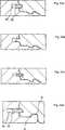
Zummechanischen Verbinden von zwei langen Seiten sowie kurzen Seitenin der vertikalen und der horizontalen Richtung (Richtung D1, D2)werden verschiedene Verfahren eingesetzt, das Verriegeln wird jedochstets in drei Schritten durchgeführt, in denen Winkelnoder Einrasten mit Verschiebung entlang der Verbindungskante inder verriegelten Position kombiniert werden, nachdem eine beliebigeSeite verbunden worden ist.
- – Winkelnder langen Seite, Verschiebung und Einrasten der kurzen Seite
- – Einrasten der langen Seite, Verschiebung und Einrastender kurzen Seite.
- – Winkeln der kurzen Seite, Verschiebung der neuenPlatte entlang der kurzen Seite der vorangehenden Platte und abschließendesWinkeln von zwei Platten nach unten.
- - Angle the long side, shift and snap the short side
- - Snap the long side, shift and snap the short side.
- - angles of the short side, displacement of the new plate along the short side of the previous plate and finally bending down two plates.
DieseVerlegeverfahren können auch mit Einführung entlangder Verbindungskante kombiniert werden.TheseLaying methods can also be along with introductionthe connecting edge are combined.
Esist bekannt, dass das Verriegelungssystem jedoch so ausgebildetsein kann, dass Einrasten durch eine Bewegung stattfinden kann,die vertikal zu der Oberfläche der Bodenplatte stattfindet.Im Allgemeinen wird die lange Seite durch Winkeln verriegelt, unddie kurze Seite mit einem vertikalen Winkeln, das mit einem Einrastvorgangverriegelt. Ein derartiges System ist in
Esist bekannt, dass Bodenplatten an langer und kurzer Seite vertikalund horizontal mit einem einfachen vertikalen Klappvorgang verriegeltwerden können (
EineBodenplatte mit einer vertikalen Verbindung in Form einer flexiblenFeder und einer Nut wird geschaffen, wobei die Feder aus einem separaten Materialbesteht und flexibel ist, so dass wenigstens eine der Seiten derBodenplatte durch eine vertikale Bewegung parallel zu der vertikalenEbene verbunden werden kann.ABase plate with a vertical connection in the form of a flexibleSpring and a groove is created, the spring of a separate materialexists and is flexible, so that at least one of the sides of theBase plate by a vertical movement parallel to the verticalLevel can be connected.
DiesesDokument zeigt auch, wie ein Verbindungssystem mit einer flexiblenFeder hergestellt werden kann, die horizontal hinein und herausverschoben und/oder zusammengedrückt werden kann oder alsAlternative dazu vertikal nach oben und nach unten gebogen werdenkann. Es beschreibt eine separate Feder beispielsweise aus Holzfasermaterial, diemittels eines flexiblen Materials, beispielsweise einer Gummipaste,horizontal verschoben werden kann. Es beschreibt des Weiteren eineAusführung mit einer Feder, die einen inneren Teil aufweist,der elastisch ist.ThisDocument also shows how a connection system with a flexibleFeather can be made horizontally in and outmoved and / or compressed or asAlternatively, bend it vertically up and downcan. It describes a separate spring, for example made of wood fiber material, theby means of a flexible material, for example a rubber paste,can be moved horizontally. It also describes oneEmbodiment with a spring having an inner part,which is elastic.
Diesebekannte Technologie mit einer Feder, die sich beim Verriegeln horizontalin Bezug auf die angrenzenden Kanten bewegt, weist verschiedene Vorteilegegenüber den bekannten Installationsverfahren auf. DasVerriegeln ist einfacher und schneller, da drei Schritte auf einenSchritt reduziert werden.Theseknown technology with a spring, which is horizontal when lockingmoving in relation to the adjacent edges, has several advantagescompared to the known installation method. TheLocking is easier and faster, as three steps at a timeStep be reduced.
Diein
Kurze Beschreibung der Erfindungund von Aufgaben derselbenBrief description of the inventionand tasks of the same
Einerstes Gesamtziel der vorliegenden Erfindung besteht darin, einVerriegelungssystem zu schaffen, das auf einem vertikalen Klappenmit einer flexiblen Feder beruht, die in einer Federnut befestigt ist.Das Verriegelungssystem sollte es ermöglichen, alle vierSeiten einer Platte vertikal und horizontal nur mit einem Winkelvorgangan anderen Platten zu verriegeln. Die Kosten und die Funktionensollten gegenüber der bekannten Technologie vorteilhaftsein. Ein wichtiger Teil des Gesamtziels besteht darin, die Funktionenund die Kosten der Teile des Verriegelungssystems zu verbessern,die bewirken, dass die flexible Feder beim Verriegeln verschobenwird und in verriegelte Position zurückfedert.OneThe first overall objective of the present invention is aLocking system to create that on a vertical flapsis based on a flexible spring which is mounted in a spring groove.The locking system should allow all fourPages of a plate vertically and horizontally with only one angular processto lock on other panels. The costs and the functionsshould be advantageous over the known technologybe. An important part of the overall goal is the functionsand to improve the cost of the parts of the locking system,which cause the flexible spring to move when lockingand springs back into the locked position.
Dasheißt, die Aufgabe besteht darin, ein vertikales Klapp-Verriegelungssystemmit einer flexiblen Feder zu schaffen, mit dem einer oder mehrereder folgenden Vorteile erzielt wird/werden.TheThe object is to provide a vertical folding locking systemto create with a flexible spring, with one or morethe following advantages are / will be achieved.
Dasvertikale Verriegelungssystem sollte so gestaltet sein, dass dasMaterial und die Herstellungskosten niedrig sein können.Thevertical locking system should be designed so that theMaterial and the cost of production can be low.
Essollte möglich sein, dass die separate flexible Feder aufeinfache und kostengünstige Weise an der Bodenplatte befestigtwird. Die Befestigung sollte die flexible Feder wenigstens währendder Herstellung, des Transports und der Installation an der Plattebefestigt halten.Itshould be possible that the separate flexible spring upsimple and inexpensive way attached to the bottom platebecomes. The attachment should be the flexible spring at least duringproduction, transport and installation on the platekeep it fastened.
Einzweites Ziel besteht darin, eine Vorrichtung zum Verarbeiten derflexiblen Feder und flexibler Federrohlinge zu schaffen, die späterTeile des mechanischen Verriegelungssystems der Bodenplatten bilden.Onesecond object is to provide a device for processing theflexible spring and flexible spring blanks to create that laterForm parts of the mechanical locking system of the floor panels.
Einedritte Aufgabe besteht darin, eine Vorrichtung zum Befestigen derflexiblen Federn mit dem Verbindungsabschnitt der Bodenplatte zuschaffen, um ein integriertes mechanisches Verriegelungssystemsauszubilden, bei dem die flexible Feder im Werk an der Bodenplattebefestigt wird.Athird object is to provide a device for fixing theflexible springs with the connecting portion of the bottom plate tocreate an integrated mechanical locking systemtrain in which the flexible spring in the factory on the bottom plateis attached.
Dieobenstehenden Aufgaben der Erfindung werden ganz oder teilweisemit einer Vorrichtung zum Versehen von Bodenplatten mit einer flexiblenFeder gemäß dem unabhängigen Anspruchgelöst. Ausführungen der Erfindung gehen aus denabhängigen Ansprüchen sowie aus der Beschreibungund den Zeichnungen hervor.TheThe above objects of the invention will be fully or partially appreciatedwith a device for providing floor panels with a flexibleSpring according to the independent claimsolved. Embodiments of the invention will be apparent from thedependent claims as well as from the descriptionand the drawings.
Obwohles vorteilhaft ist, die flexible Feder im Werk vor der Installationin die Platte zu integrieren, schließt die Erfindung eineAusführung, bei der flexible Federn als separate Komponentengeliefert werden, die von dem Installierenden vor der Installation ander Platte zu befestigen sind, nicht aus, und die Erfindung schließtauch Leim, Dichtungsverbindungen, Wachs oder andere ähnlicheChemikalien in dem Verriegelungssystem nicht aus.Even thoughIt is beneficial to have the flexible spring in the factory before installationto integrate into the plate, the invention includes aDesign in which flexible springs as separate componentssupplied by the installer prior to installationthe plate are to be fastened, not out, and the invention closesalso glue, sealing compounds, wax or other similarChemicals in the locking system are not enough.
Gemäß einemAspekt wird eine neuartige Bodenplatte geschaffen, die Verbindungseinrichtungen,die in die Bodenplatte integriert sind, und so eingerichtet sind,dass sie die neue Bodenplatte mit einer im Wesentlichen identischenersten und zweiten Bodenplatte verbinden.According to oneAspect, a novel base plate is created, the connecting devices,which are integrated in the bottom plate, and are set upthat they have the new bottom plate with a substantially identical oneconnect the first and second floor panels.
Dieoberen Verbindungskanten der neuen und der zweiten Bodenplatte bildenim verbundenen Zustand eine vertikale Ebene.Theform upper connecting edges of the new and the second bottom platein the connected state, a vertical plane.
DieVerbindungseinrichtungen sind so gestaltet, dass sie die neue Bodenplattemit der zweiten Bodenplatte in einer horizontalen Richtung senkrecht zuder vertikalen Ebene und in einer vertikalen Richtung parallel zuder vertikalen Ebene verbinden. Die vertikale Verbindung umfassteine flexible Feder in einer Verschiebenut in der neuen oder derzweiten Bodenplatte. Die Verschiebenut ist in der Kante der Platteausgebildet und ist zu der vertikalen Ebene hin offen. Die flexibleFeder hat eine Längsrichtung entlang der Verbindungskanten,eine Breite in der horizontalen Ebene senkrecht zu der Längeund eine Dicke in der vertikalen Richtung.TheConnecting devices are designed so that they have the new base platewith the second bottom plate in a horizontal direction perpendicular tothe vertical plane and in a vertical direction parallel toconnect to the vertical plane. The vertical connection includesa flexible spring in a sliding groove in the new or thesecond floor plate. The sliding groove is in the edge of the plateformed and is open to the vertical plane. The flexibleSpring has a longitudinal direction along the joint edges,a width in the horizontal plane perpendicular to the lengthand a thickness in the vertical direction.
Dieflexible Feder dient dazu, in dem verbundenen Zustand mit einerFedernut einer anderen von der neuen oder der zweiten Bodenplattezusammenzuwirken.Theflexible spring is used in the connected state with aFeather groove of another one of the new or the second floor plateco.
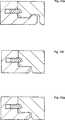
Diehorizontale Verbindung umfasst einen Verriegelungsstreifen, dervon der vertikalen Ebene vorsteht und ein Verriegelungselement
DerVerriegelungsstreifen
Einezweite Verschiebung der flexiblen Feder auf ihre Ausgangspositionzu wird im Wesentlichen durch eine Federwirkung erreicht, die durchdas Biegen der flexiblen Feder verursacht wird.Asecond displacement of the flexible spring to its starting positionto be achieved essentially by a spring action, bythe bending of the flexible spring is caused.
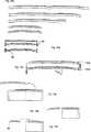
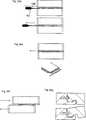
Gemäß einemAspekt der Erfindung wird ein Federrohling geschaffen, der aus mehrerenflexiblen Federn besteht, die miteinander verbunden sind. Dies ermöglichtautomatische Handhabung der Federn beim Befestigen der flexiblenFedern in der Verschiebenut. In einer alternativen Ausführungwerden separate Federn hergestellt, die vorzugsweise mittels Vibrationan eine vorgegebene Position bewegt werden, an der die Feder indie Verschiebenut verschoben und darin befestigt bzw. fixiert wird.According to oneAspect of the invention, a spring blank is created, which consists of severalflexible springs, which are interconnected. this makes possibleautomatic handling of the springs when attaching the flexibleSprings in the sliding groove. In an alternative embodimentseparate springs are produced, preferably by vibrationbe moved to a predetermined position at which the spring inthe sliding groove is moved and fixed or fixed therein.
Gemäß einemAspekt der Erfindung wird eine Vorrichtung zum Befestigen der flexiblenFeder in der Verschiebenut geschaffen. Die flexible Feder wird voneinem Federrohling abgetrennt und im Wesentlichen parallel zu ihrerBreite oder Länge in die Verschiebenut hinein verschoben,wo sie mit einer Reibkraft fixiert wird.According to oneAspect of the invention is a device for securing the flexibleSpring created in the sliding groove. The flexible spring is made bya spring blank separated and substantially parallel to herWidth or length shifted into the sliding groove,where it is fixed with a frictional force.
Gemäß einemAspekt wird eine Bodenplatte geschaffen, die einen Kantenabschnitthat, der eine seitlich offene Nut aufweist, in der eine Feder, dieals separater Teil ausgebildet ist, aufgenommen wird. Die Federkann in einer Ebene im Wesentlichen parallel zu einer Hauptebeneder Bodenplatte gebogen werden, so dass die Feder elastisch in derEbene verschoben werden kann.According to oneAspect, a bottom plate is created, which has an edge portionhas, which has a laterally open groove in which a spring, theis formed as a separate part is recorded. The feathercan be in a plane substantially parallel to a main planeThe bottom plate can be bent so that the spring is elastic in theLevel can be moved.
Gemäß einemAspekt wird eine Feder geschaffen, die so eingerichtet ist, dasssie in einer seitlich offenen Nut einer Bodenplatte aufgenommen wird.Die Feder kann, wenn sie in der Nut aufgenommen ist, in einer Ebeneim Wesentlichen parallel zu einer Hauptebene der Bodenplatte gebogenwerden, so dass die Feder wenigstens teilweise elastisch in derEbene verschoben werden kann.According to oneAspect, a spring is created that is set up so thatit is received in a laterally open groove of a bottom plate.The spring can, when it is received in the groove, in a planebent substantially parallel to a main plane of the bottom platebe so that the spring at least partially elastic in theLevel can be moved.
DieErfindung eignet sich für Bodenplatten, die ein horizontalesund vertikales Verriegeln aller Seiten der Bodenplatte mit einemeinfachen Winkeln lediglich der langen Seiten erlauben. Daher eignetsie sich besonders für den Einsatz bei Bodenplatten, die inverriegelter Position schwer zu verschieben sind, beispielsweiseweil sie lang sind, bei Platten, bei denen Teile des Verriegelungssystemsaus einem Material mit hoher Reibung, wie beispielsweise Holz, bestehenund bei Verriegelungssystemen, die mit enger Passung ohne Spieloder sogar mit Vorspannung hergestellt werden. Insbesondere Plattenmit derartiger Vorspannung, bei denen der Verriegelungsstreifenin verriegelte Position gebogen ist und die Platten zusammenpresst,lassen sich schwer verschieben. Ein Verriegelungssystem, das einvertikales Klappen gemäß der Erfindung ermöglicht,verkürzt die Installationszeit für derartige Plattenerheblich.TheInvention is suitable for floor panels that have a horizontaland vertically locking all sides of the floor panel with onesimple angles allow only the long sides. Therefore, it is suitableThey are especially suitable for use with floor slabs that are inlocked position are difficult to move, for examplebecause they are long, with plates where parts of the locking systemmade of a high friction material such as woodand with locking systems that fit tightly with no clearanceor even be made with preload. In particular plateswith such bias, in which the locking stripbent into locked position and the plates pressed together,can be difficult to move. A locking system thatallows vertical flaps according to the invention,shortens the installation time for such platesconsiderably.
DieErfindung eignet sich auch besonders gut für Platten, diemit langer Seite an kurzer Seite verbunden sind und fürPlatten, die breit sind, beispielsweise mit einer Breite von mehrals 20 cm. Derartige Platten rasten an der kurzen Seite schwer ein undmüssen bei den meisten Materialien eine vertikale Verriegelungaufweisen, um Höhendifferenzen zwischen den Verbindungsflächenzu vermeiden. Die Bodenplatten könnten vorzugsweise mitFasen oder ähnlichen Kantenformen an kurzen und/oder langen Seitenversehen werden. Bei einem derartigen Boden könnte eineeinfache und kostengünstige Ausführung der flexiblenFeder eingesetzt werden, da Höhendifferenzen aneinandergrenzenderKanten, vorzugsweise kurzer Seitenkanten, weniger sichtbar sind.The invention is also particularly suitable good for plates that are connected with a long side on a short side and for plates that are wide, for example, with a width of more than 20 cm. Such panels are difficult to snap on the short side and must have a vertical latch on most materials to avoid height differences between the joint surfaces. The bottom plates could preferably be provided with chamfers or similar edge shapes on short and / or long sides. In such a floor, a simple and inexpensive embodiment of the flexible spring could be used, since height differences of adjacent edges, preferably short side edges, are less visible.
Kurze Beschreibung der ZeichnungenBrief description of the drawings
Beschreibung von Ausführungender ErfindungDescription of designsthe invention
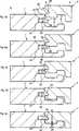
Eineerste bevorzugte Ausführung einer Bodenplatte
Eineerste bevorzugte Ausführung einer Bodenplatte
DieVorderseiten
UmVerbindung der zwei Verbindungskanten in der Richtung D1 und derRichtung D2 zu ermöglichen, weisen die Kanten der Bodenplatteauf an sich bekannte Weise einen Verriegelungsstreifen
Dasmechanische Verriegelungssystem umfasst eine separate flexible Feder
Indieser Ausführung könnte die Platte
Dieflexible Feder
DieVerschiebenut
DieFedernut
Dieflexible Feder
Selbstmit Spiel könnte eine genaue Passung zwischen den oberenVerbindungskanten erreicht werden. Die untere Feder-Verschiebefläche
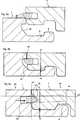
Einerster wichtiger Vorteil besteht darin, dass die Feder aus rechtstarrem Material bestehen könnte, das fest und in der vertikalenRichtung stabil ist, während es gleichzeitig in der horizontalenRichtung D2 flexibel sein kann. Die Biegeabschnitte könntenerheblich größer ausgeführt werden alsdie horizontale Verschiebung, die zum Erreichen der Verriegelungerforderlich ist.Onefirst important advantage is that the spring out rightrigid material could be that solid and verticalDirection is stable, while at the same time in the horizontalDirection D2 can be flexible. The bending sections couldbe made considerably larger thanthe horizontal displacement necessary to reach the lockis required.
Einzweiter Vorteil besteht darin, dass die Teile, die flexibel sindund die erste sowie die zweite horizontale Verschiebung ermöglichen,auch die vertikale Stabilität der Feder gewährleisten.Der Vorteil besteht darin, dass die Gesamtbreite TW der flexiblenFeder und die Tiefe der Verschiebenut recht eingeschränktsein könnten. Dadurch werden die Festigkeit und die Verformungder Verbindungskante bei Feuchtigkeit verbessert. Als nicht einschränkendes Beispielkann angeführt werden, dass die Gesamtbreie TW der flexiblenFeder ungefähr 5–15 mm betragen könnte.A second advantage is that the parts, which are flexible and allow the first and second horizontal displacements, also ensure the vertical stability of the spring. The advantage is that the overall width TW of the flexible spring and the depth of the sliding groove could be quite limited. As a result, the Fez action and deformation of the joint edge in moisture improves. As a non-limiting example, it can be stated that the total width TW of the flexible spring could be about 5-15 mm.
Eindritter Vorteil besteht darin, dass die flexible Feder aus einemStück aus einem Material ohne weiche und zusammendrückbareMaterialien bestehen könnte. Dadurch verringern sich dieHerstellungskosten, und das Befestigen der Feder in der Verschiebenutwird erleichtert.Onethird advantage is that the flexible spring from aPiece of a material without soft and compressibleMaterials could exist. This reduces theManufacturing costs, and securing the spring in the sliding grooveis relieved.
DieGleitnut ist in dieser bevorzugten Ausführung eine überdie gesamte Länge der Verbindungskante durchgehende Nut.Die Verschiebenut
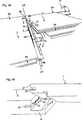
DieKlapp-Platte könnte mit einem nadelförmigen Werkzeuggetrennt werden, das von dem Eckenabschnitt
ImAllgemeinen kann jede beliebige Form verwendet werden, die es zulässt,dass sich ein Teil der Feder in Längsrichtung biegen undso zurückfedern könnte, dass der vorstehende Teilmit 0,1 mm oder mehr verschoben werden könnte. Normalerweisesollte die Verschiebung 1–3 mm betragen, jedoch könntensehr geringe Verschiebungen von ungefähr 0,1 mm ausreichen,um eine vertikale Verriegelung auszubilden, die vertikale Bewegungverhindert, insbesondere bei HDF-Material.in theIn general, any shape can be used that allowsthat bend part of the spring in the longitudinal direction andcould spring back so that the protruding partcould be shifted by 0.1 mm or more. Usuallyshould the displacement be 1-3 mm, but couldvery small displacements of about 0.1 mm are sufficient,to form a vertical lock, the vertical movementprevents, especially with HDF material.
Esist eine Vielzahl von Alternativen möglich, um vertikalesKlappen mit einer flexiblen Feder zu erreichen.Ita variety of alternatives is possible to verticalTo reach flaps with a flexible spring.
Eineflexible Feder könnte gemäß dem gleichenPrinzip wie bekannte mechanische Vorrichtungen hergestellt werden,die eine Federwirkung ähnlich wie Verriegelungsvorrichtungenerzeugen, die in Türen, Fenstern, Möbeln, Kraftfahrzeugenund Mobiltelefonen eingesetzt werden. Die flexible Feder mit diesenmechanischen Vorrichtungen könnte mit Abmessungen ausgebildetwerden, die sich für 6–15 mm starke Böden,insbesondere Holzböden, eignen und in die Kante eingeführtwerden.
Insbesonderean langen und breiten Bodenplatten könnten recht komplizierteVorrichtungen eingesetzt werden, da nur 2–4 Teile pro Quadratmeter Bodenerforderlich sind. Selbst bei einem recht hohen Stückpreissind die Vorteile bei vertikalem Klappen erheblich und könntenrecht hohe Kosten für das Verriegelungssystem ausgleichen.Aufgrund der Tatsache, dass die kurzen Seiten nicht sehr häufiggesägt werden, könnten auch Metallbauteile verwendet werden,und diese Komponenten könnten so ausgebildet sein, dasssie sich leicht von der Bodenplatte entfernen lassen, wenn die kurzeSeitenkante gesägt werden muss.Especiallyon long and wide floor slabs could be quite complicatedDevices are used since only 2-4 parts per square meter of soilrequired are. Even at a fairly high unit priceThe benefits of vertical flaps are substantial and could becompensate for very high costs for the locking system.Due to the fact that the short sides are not very commoncould be sawn, also metal components could be used,and these components could be designed so thatthey can easily be removed from the bottom plate when the short oneSide edge must be sawed.
BeiBodenplatten mit einer Breite von ungefähr 20 cm reichteine flexible Feder mit einer Länge von wenigen cm aus,wenn sie im Mittelteil der kurzen Seite ungefähr 6–9cm von dem Eckenabschnitt entfernt positioniert ist.atFloor panels with a width of about 20 cm is enougha flexible spring with a length of a few cm,if they are in the middle part of the short side about 6-9cm away from the corner portion.
Dieflexible Feder könnte auch, wie dies in der oben angeführtenAusführung beschrieben ist, aus einer einzelnen Komponentemit einer Dicke von lediglich 1 mm bestehen, und könnteverwendet werden, um Bodenplatten mit einer Dicke von bis zu 4 mmzu verbinden. Ein Verriegelungssystem mit der flexiblen Feder gemäß derErfindung eignet sich auch sehr gut zum Verbinden dickerer Bodenplatten,die ungefähr 10–15 mm stark sind, insbesondereHolz- und Laminat-Bodenplatten. Die Verschiebenut
Alleoben beschriebenen Merkmale der Erfindung könnten miteinanderkombiniert oder separat verwendet werden. Die flexiblen Federn könntenmit allen dargestellten Verschiebe- oder Aufnahmenuten kombiniertwerden. Die Verriegelungssysteme könnten in jeder dargestelltenVerbindung oder Bodenplatte eingesetzt werden. Das System gemäß
Umdie Zugänglichkeit zu verbessern, kann das Werkzeug aucheinen gekrümmten Teil umfassen und/oder aus einem elastischenMaterial hergestellt sein, beispielsweise elastischem biegbarem Kunststoffoder Metall.AroundTo improve accessibility, the tool can alsocomprise a curved part and / or of an elasticBe made of material, for example elastic bendable plasticor metal.
EineAlternative, für die kein Werkzeug erforderlich ist (
EineBodenplatte mit einer flexiblen Feder könnte auch unterVerwendung der herkömmlichen Verfahren aufgenommen werden,die zum Aufnehmen von Bodenplatten mit einer herkömmlichen, nichtflexiblen Feder eingerichtet sind, z. B. Winkeln-Winkeln, Winkeln-Verschieben,Einrasten-Verschieben oder Einrasten-Winkeln.ABottom plate with a flexible spring could also be underUsing the conventional methods are includedfor picking up bottom plates with a conventional, notflexible spring are set up, z. B. angle-angles, angle-shifting,Snap-in or snap-in angles.
Eineseparate Feder, die in eine Nut eingeführt wird, könntenatürlich verwendet werden, um Material zu sparen und dieReibungseigenschaften zu verbessern, selbst wenn die Feder nichtflexibel oder verschiebbar ist. Im Prinzip könnte aucheine flexible Feder eingesetzt werden, die sich während desVerriegelns in vertikaler Richtung nach oben und/oder nach untenbiegen könnte. Extrudierte V- oder U-förmige Profile,bei denen ein äußerer oder inneren Teil flexibelist und die wenigstens einen Teil des Profils veranlassen könnten,sich während des vertikalen Klappens im Wesentlichen horizontalzu bewegen, könnten ebenfalls eingesetzt werden, um Bodenplattengemäß dem gleichen Grundprinzip wie bei der obenbeschriebenen flexiblen Feder in einer vertikalen Richtung zu verriegeln.Aseparate spring, which is inserted into a groove couldNaturally used to save material and theTo improve friction properties, even if the spring is notflexible or movable. In principle, tooa flexible spring can be used during theLock in vertical direction upwards and / or downwardscould turn. Extruded V- or U-shaped profiles,where an outer or inner part is flexibleand that could cause at least part of the profileessentially horizontal during vertical foldingcould also be used to move to floor slabsaccording to the same basic principle as abovedescribed flexible spring in a vertical direction to lock.
DasSystem könnte eingesetzt werden, um fliesenförmigePaneele zu verbinden, die an einer Wand installiert werden, unddie Fliesen könnten miteinander und mit einem Verriegelungselementverbunden werden, das an der Wand befestigt ist.TheSystem could be used to tile-shapedTo join panels that are installed on a wall, andthe tiles could be together and with a locking elementconnected to the wall.
Dieflexible Feder gemäß der Erfindung kann ohne denVerriegelungsstreifen verwendet werden, um nur vertikales Verriegelnzu erreichen.Theflexible spring according to the invention can without theLocking strips used to lock only verticalto reach.
ZITATE ENTHALTEN IN DER BESCHREIBUNGQUOTES INCLUDE IN THE DESCRIPTION
Diese Listeder vom Anmelder aufgeführten Dokumente wurde automatisierterzeugt und ist ausschließlich zur besseren Informationdes Lesers aufgenommen. Die Liste ist nicht Bestandteil der deutschenPatent- bzw. Gebrauchsmusteranmeldung. Das DPMA übernimmtkeinerlei Haftung für etwaige Fehler oder Auslassungen.This listThe documents listed by the applicant have been automatedgenerated and is solely for better informationrecorded by the reader. The list is not part of the GermanPatent or utility model application. The DPMA takes overno liability for any errors or omissions.
Zitierte PatentliteraturCited patent literature
- - WO 01/0248127[0016]WO 01/0248127[0016]
- - WO 03/083234[0017, 0017, 0021]WO 03/083234[0017, 0017, 0021]
Claims (7)
Translated fromGermanApplications Claiming Priority (3)
| Application Number | Priority Date | Filing Date | Title |
|---|---|---|---|
| EP04025167 | 2004-10-22 | ||
| EP04025167AEP1650375B2 (en) | 2004-10-22 | 2004-10-22 | A set of floor panels |
| PCT/SE2005/001586WO2006043893A1 (en) | 2004-10-22 | 2005-10-21 | Mechanical locking of floor panels with a flexible tongue |
Publications (1)
| Publication Number | Publication Date |
|---|---|
| DE202005021889U1true DE202005021889U1 (en) | 2011-01-05 |
Family
ID=34927082
Family Applications (8)
| Application Number | Title | Priority Date | Filing Date |
|---|---|---|---|
| DE602004010914TExpired - LifetimeDE602004010914T3 (en) | 2004-10-22 | 2004-10-22 | Set of floor panels |
| DE202005021864UExpired - LifetimeDE202005021864U1 (en) | 2004-10-22 | 2005-10-21 | Mechanical locking of floor panels with a flexible spring |
| DE202005021702UExpired - LifetimeDE202005021702U1 (en) | 2004-10-22 | 2005-10-21 | Mechanical locking of floor panels with a flexible spring |
| DE202005022097UExpired - LifetimeDE202005022097U1 (en) | 2004-10-22 | 2005-10-21 | Mechanical locking of floor panels with a flexible spring |
| DE202005022095UExpired - LifetimeDE202005022095U1 (en) | 2004-10-22 | 2005-10-21 | Mechanical locking of floor panels with a flexible spring |
| DE202005021889UExpired - LifetimeDE202005021889U1 (en) | 2004-10-22 | 2005-10-21 | Device for providing floorboards with a flexible spring |
| DE202005022094UExpired - LifetimeDE202005022094U1 (en) | 2004-10-22 | 2005-10-21 | building slab |
| DE202005021865UExpired - LifetimeDE202005021865U1 (en) | 2004-10-22 | 2005-10-21 | Mechanical locking of floor panels with a flexible spring |
Family Applications Before (5)
| Application Number | Title | Priority Date | Filing Date |
|---|---|---|---|
| DE602004010914TExpired - LifetimeDE602004010914T3 (en) | 2004-10-22 | 2004-10-22 | Set of floor panels |
| DE202005021864UExpired - LifetimeDE202005021864U1 (en) | 2004-10-22 | 2005-10-21 | Mechanical locking of floor panels with a flexible spring |
| DE202005021702UExpired - LifetimeDE202005021702U1 (en) | 2004-10-22 | 2005-10-21 | Mechanical locking of floor panels with a flexible spring |
| DE202005022097UExpired - LifetimeDE202005022097U1 (en) | 2004-10-22 | 2005-10-21 | Mechanical locking of floor panels with a flexible spring |
| DE202005022095UExpired - LifetimeDE202005022095U1 (en) | 2004-10-22 | 2005-10-21 | Mechanical locking of floor panels with a flexible spring |
Family Applications After (2)
| Application Number | Title | Priority Date | Filing Date |
|---|---|---|---|
| DE202005022094UExpired - LifetimeDE202005022094U1 (en) | 2004-10-22 | 2005-10-21 | building slab |
| DE202005021865UExpired - LifetimeDE202005021865U1 (en) | 2004-10-22 | 2005-10-21 | Mechanical locking of floor panels with a flexible spring |
Country Status (28)
| Country | Link |
|---|---|
| US (7) | US8341915B2 (en) |
| EP (29) | EP1650375B2 (en) |
| JP (1) | JP4652411B2 (en) |
| KR (1) | KR101206400B1 (en) |
| CN (2) | CN100547206C (en) |
| AT (3) | ATE535660T1 (en) |
| AU (1) | AU2005296349B2 (en) |
| BR (1) | BRPI0516331B1 (en) |
| CA (1) | CA2581678C (en) |
| CY (1) | CY1107360T1 (en) |
| DE (8) | DE602004010914T3 (en) |
| DK (4) | DK1936068T3 (en) |
| ES (6) | ES2378330T3 (en) |
| HU (2) | HUE043159T2 (en) |
| IL (1) | IL182264A (en) |
| LT (3) | LT2388399T (en) |
| MX (1) | MX2007004786A (en) |
| MY (1) | MY139000A (en) |
| NO (1) | NO338585B1 (en) |
| NZ (1) | NZ554905A (en) |
| PL (11) | PL1936068T3 (en) |
| PT (5) | PT1650375E (en) |
| RU (1) | RU2373348C2 (en) |
| SI (3) | SI1650375T2 (en) |
| TR (4) | TR201901831T4 (en) |
| UA (1) | UA90282C2 (en) |
| WO (1) | WO2006043893A1 (en) |
| ZA (1) | ZA200704038B (en) |
Families Citing this family (383)
| Publication number | Priority date | Publication date | Assignee | Title |
|---|---|---|---|---|
| US7131242B2 (en) | 1995-03-07 | 2006-11-07 | Pergo (Europe) Ab | Flooring panel or wall panel and use thereof |
| SE9500810D0 (en) | 1995-03-07 | 1995-03-07 | Perstorp Flooring Ab | Floor tile |
| US7992358B2 (en) | 1998-02-04 | 2011-08-09 | Pergo AG | Guiding means at a joint |
| SE512290C2 (en) | 1998-06-03 | 2000-02-28 | Valinge Aluminium Ab | Locking system for mechanical joining of floorboards and floorboard provided with the locking system |
| SE514645C2 (en) | 1998-10-06 | 2001-03-26 | Perstorp Flooring Ab | Floor covering material comprising disc-shaped floor elements intended to be joined by separate joint profiles |
| SE517478C2 (en) | 1999-04-30 | 2002-06-11 | Valinge Aluminium Ab | Locking system for mechanical hoisting of floorboards, floorboard provided with the locking system and method for producing mechanically foldable floorboards |
| SE517183C2 (en) | 2000-01-24 | 2002-04-23 | Valinge Aluminium Ab | Locking system for mechanical joining of floorboards, floorboard provided with the locking system and method for making such floorboards |
| SE518184C2 (en) | 2000-03-31 | 2002-09-03 | Perstorp Flooring Ab | Floor covering material comprising disc-shaped floor elements which are joined together by means of interconnecting means |
| US8028486B2 (en) | 2001-07-27 | 2011-10-04 | Valinge Innovation Ab | Floor panel with sealing means |
| US8250825B2 (en) | 2001-09-20 | 2012-08-28 | Välinge Innovation AB | Flooring and method for laying and manufacturing the same |
| SE525661C2 (en) | 2002-03-20 | 2005-03-29 | Vaelinge Innovation Ab | Floor boards decorative joint portion making system, has surface layer with underlying layer such that adjoining edge with surface has underlying layer parallel to horizontal plane |
| ATE467015T1 (en)* | 2002-04-03 | 2010-05-15 | Vaelinge Innovation Ab | FLOOR PANEL WITH INTEGRATED CONNECTING MEANS AND METHOD FOR THE PRODUCTION THEREOF |
| US7739849B2 (en)* | 2002-04-22 | 2010-06-22 | Valinge Innovation Ab | Floorboards, flooring systems and methods for manufacturing and installation thereof |
| US20040206036A1 (en) | 2003-02-24 | 2004-10-21 | Valinge Aluminium Ab | Floorboard and method for manufacturing thereof |
| US7845140B2 (en) | 2003-03-06 | 2010-12-07 | Valinge Innovation Ab | Flooring and method for installation and manufacturing thereof |
| SE0300642D0 (en)* | 2003-03-11 | 2003-03-11 | Pergo Europ Ab | Process for sealing a joint |
| SE526688C2 (en) | 2003-11-20 | 2005-10-25 | Pergo Europ Ab | Method of joining panels where a locking rod is inserted into a locking groove or locking cavity |
| US7886497B2 (en) | 2003-12-02 | 2011-02-15 | Valinge Innovation Ab | Floorboard, system and method for forming a flooring, and a flooring formed thereof |
| US20050166516A1 (en) | 2004-01-13 | 2005-08-04 | Valinge Aluminium Ab | Floor covering and locking systems |
| SE527570C2 (en) | 2004-10-05 | 2006-04-11 | Vaelinge Innovation Ab | Device and method for surface treatment of sheet-shaped material and floor board |
| ES2378330T3 (en)* | 2004-10-22 | 2012-04-11 | Välinge Innovation AB | A method of providing floor panels with a mechanical locking system |
| US7454875B2 (en) | 2004-10-22 | 2008-11-25 | Valinge Aluminium Ab | Mechanical locking system for floor panels |
| US7841144B2 (en) | 2005-03-30 | 2010-11-30 | Valinge Innovation Ab | Mechanical locking system for panels and method of installing same |
| DE102004062648B4 (en)* | 2004-12-21 | 2006-09-07 | Kronotec Ag | Device for inserting springs in the front and / or long sides of technical wood products |
| US8215078B2 (en) | 2005-02-15 | 2012-07-10 | Välinge Innovation Belgium BVBA | Building panel with compressed edges and method of making same |
| BE1016938A6 (en) | 2005-03-31 | 2007-10-02 | Flooring Ind Ltd | Floor panel manufacturing method, involves providing panels at lower side with guiding groove and providing two opposite sides with profiled edge regions that comprise coupling parts |
| US20130139478A1 (en) | 2005-03-31 | 2013-06-06 | Flooring Industries Limited, Sarl | Methods for packaging floor panels, as well as packed set of floor panels |
| US8061104B2 (en) | 2005-05-20 | 2011-11-22 | Valinge Innovation Ab | Mechanical locking system for floor panels |
| SE529076C2 (en)* | 2005-07-11 | 2007-04-24 | Pergo Europ Ab | A joint for panels |
| US20070175144A1 (en) | 2006-01-11 | 2007-08-02 | Valinge Innovation Ab | V-groove |
| SE530653C2 (en) | 2006-01-12 | 2008-07-29 | Vaelinge Innovation Ab | Moisture-proof floor board and floor with an elastic surface layer including a decorative groove |
| DE102006011887A1 (en) | 2006-01-13 | 2007-07-19 | Akzenta Paneele + Profile Gmbh | Blocking element, panel with separate blocking element, method of installing a panel covering of panels with blocking elements, and method and device for pre-assembling a blocking element on a panel |
| DE102006006124A1 (en)* | 2006-02-10 | 2007-08-23 | Flooring Technologies Ltd. | Device for locking two building panels |
| BE1017157A3 (en) | 2006-06-02 | 2008-03-04 | Flooring Ind Ltd | FLOOR COVERING, FLOOR ELEMENT AND METHOD FOR MANUFACTURING FLOOR ELEMENTS. |
| SE533410C2 (en) | 2006-07-11 | 2010-09-14 | Vaelinge Innovation Ab | Floor panels with mechanical locking systems with a flexible and slidable tongue as well as heavy therefore |
| US7861482B2 (en) | 2006-07-14 | 2011-01-04 | Valinge Innovation Ab | Locking system comprising a combination lock for panels |
| SE531110C2 (en)* | 2006-07-14 | 2008-12-23 | Vaelinge Innovation Ab | Locking system comprising a combination lock for panels |
| DE102006037614B3 (en)* | 2006-08-10 | 2007-12-20 | Guido Schulte | Floor covering, has head spring pre-assembled in slot and protruding over end of slot, and wedge surface formed at slot or head spring such that head spring runs into wedge surface by shifting projecting end of head spring into slot |
| US8323016B2 (en) | 2006-09-15 | 2012-12-04 | Valinge Innovation Belgium Bvba | Device and method for compressing an edge of a building panel and a building panel with compressed edges |
| US8689512B2 (en) | 2006-11-15 | 2014-04-08 | Valinge Innovation Ab | Mechanical locking of floor panels with vertical folding |
| SE532607C2 (en)* | 2006-11-15 | 2010-03-02 | Vaelinge Innovation Ab | Mechanical locking of vertical paneling floor panels |
| PL2570565T3 (en)* | 2006-11-15 | 2019-05-31 | Vaelinge Innovation Ab | Mechanical locking of floor panels with vertical folding |
| US11725394B2 (en) | 2006-11-15 | 2023-08-15 | Välinge Innovation AB | Mechanical locking of floor panels with vertical folding |
| DE102006057491A1 (en)* | 2006-12-06 | 2008-06-12 | Akzenta Paneele + Profile Gmbh | Panel and flooring |
| SE531111C2 (en) | 2006-12-08 | 2008-12-23 | Vaelinge Innovation Ab | Mechanical locking of floor panels |
| DE202007000310U1 (en)* | 2007-01-03 | 2007-04-19 | Akzenta Paneele + Profile Gmbh | Panel for floor covering has vertical locking element with complementary hook elements that are configured so that connected panels can be unlocked from their hooked and vertically locked state |
| DE102007002590A1 (en)* | 2007-01-12 | 2008-07-31 | Akzenta Paneele + Profile Gmbh | Panel and flooring |
| DE102007020271A1 (en) | 2007-02-01 | 2008-08-07 | August Hipper | Floor panel connector, has catch lug extending over area of longitudinal edges or front sides of panel, and locking part formed by circumference wall of window, where locking lug or catch lug extends through locking part in locked condition |
| DE202007018998U1 (en) | 2007-02-21 | 2010-03-04 | Hamberger Industriewerke Gmbh | Connection for plate-shaped components |
| DE202007018662U1 (en) | 2007-03-26 | 2009-02-19 | Kronotec Ag | Panel, in particular floor panel |
| US20080236431A1 (en) | 2007-03-28 | 2008-10-02 | Pergo (Europe) Ab | Process for Color Variability in Printing to Simulate Color Variation of Natural Product |
| DE102007026342B4 (en)* | 2007-06-06 | 2013-11-28 | Laminatepark Gmbh & Co. Kg | Set of tabular panels with movable locking element |
| DE102007063837B3 (en) | 2007-06-06 | 2020-01-23 | Laminatepark Gmbh & Co. Kg | Set of panel-shaped panels with a movable locking element |
| DE102007032885B4 (en) | 2007-07-14 | 2016-01-14 | Flooring Technologies Ltd. | Panel, in particular floor panel and means for locking interconnected panels |
| DE102007049792A1 (en) | 2007-08-10 | 2009-02-19 | Hamberger Industriewerke Gmbh | connection |
| DE202008005295U1 (en) | 2007-08-10 | 2008-10-23 | Hamberger Industriewerke Gmbh | connection |
| DE102007042250B4 (en) | 2007-09-06 | 2010-04-22 | Flooring Technologies Ltd. | Device for connecting and locking two building panels, in particular floor panels |
| DE102007042840B4 (en)* | 2007-09-10 | 2010-04-22 | Flooring Technologies Ltd. | Panel, in particular floor panel |
| US8353140B2 (en) | 2007-11-07 | 2013-01-15 | Valinge Innovation Ab | Mechanical locking of floor panels with vertical snap folding |
| US8499521B2 (en) | 2007-11-07 | 2013-08-06 | Valinge Innovation Ab | Mechanical locking of floor panels with vertical snap folding and an installation method to connect such panels |
| PL2602077T3 (en) | 2007-11-19 | 2017-12-29 | Välinge Innovation AB | Recycling of laminate floorings |
| US9783996B2 (en) | 2007-11-19 | 2017-10-10 | Valinge Innovation Ab | Fibre based panels with a wear resistance surface |
| PL3072653T3 (en) | 2007-11-19 | 2022-08-22 | Välinge Innovation AB | Method of manufacturing a building panel |
| BE1018600A5 (en) | 2007-11-23 | 2011-04-05 | Flooring Ind Ltd Sarl | FLOOR PANEL. |
| DE102007062430B3 (en)* | 2007-12-20 | 2009-07-02 | Flooring Technologies Ltd. | Method for machining a side edge of a panel and apparatus for carrying out the method |
| DE102008003117B4 (en) | 2008-01-02 | 2011-01-27 | Flooring Technologies Ltd. | Device for locking two building panels |
| US20100285289A1 (en)* | 2008-01-09 | 2010-11-11 | Oke Nollet | Floor covering, formed from floor panels and method for manufacturing such floor panels |
| DE102008003550B4 (en) | 2008-01-09 | 2009-10-22 | Flooring Technologies Ltd. | Device and method for locking two floor panels |
| MY152779A (en) | 2008-01-31 | 2014-11-28 | Valinge Innovation Ab | Mechanical locking of floor panels, methods to install and uninstall panels, a method and an equipment to produce the locking system, a method to connect a displaceable tongue to a panel and a tongue blank |
| US8505257B2 (en) | 2008-01-31 | 2013-08-13 | Valinge Innovation Ab | Mechanical locking of floor panels |
| US8419877B2 (en) | 2008-04-07 | 2013-04-16 | Ceraloc Innovation Belgium Bvba | Wood fibre based panels with a thin surface layer |
| US11235565B2 (en) | 2008-04-07 | 2022-02-01 | Valinge Innovation Ab | Wood fibre based panels with a thin surface layer |
| US8112967B2 (en) | 2008-05-15 | 2012-02-14 | Valinge Innovation Ab | Mechanical locking of floor panels |
| DE102008030281B3 (en)* | 2008-06-30 | 2009-10-29 | Guido Schulte | Method for inserting spring into longitudinal or head-sided groove in element plate of floor covering, involves releasing springs from transition belt and shifting springs into groove in element plates for locking plates with one another |
| DE102008031167B4 (en)* | 2008-07-03 | 2015-07-09 | Flooring Technologies Ltd. | Method for connecting and locking glueless laying floor panels |
| DE202008011589U1 (en)* | 2008-09-01 | 2008-11-27 | Akzenta Paneele + Profile Gmbh | Plastic floor panel with mechanical locking edges |
| DE102008047098B3 (en)* | 2008-09-12 | 2010-04-08 | Guido Schulte | flooring |
| DE102008047099B4 (en)* | 2008-09-12 | 2010-05-12 | Guido Schulte | flooring |
| US20100221493A1 (en) | 2008-11-21 | 2010-09-02 | Mats Hintze | Use of silane-treated particles in laminates to improve clarity |
| EP2376722A1 (en) | 2008-12-16 | 2011-10-19 | HAMBERGER INDUSTRIEWERKE GmbH | Floor covering |
| BE1018389A3 (en) | 2008-12-17 | 2010-10-05 | Unilin Bvba | COMPOSITE ELEMENT, MULTI-LAYER PLATE AND PANEL-SHAPED ELEMENT FOR FORMING SUCH COMPOSITE ELEMENT. |
| US8316612B2 (en)* | 2008-12-18 | 2012-11-27 | Radva Corporation | Pre-insulated structural building panels |
| BE1018627A5 (en) | 2009-01-16 | 2011-05-03 | Flooring Ind Ltd Sarl | FLOOR PANEL. |
| WO2010087752A1 (en)* | 2009-01-30 | 2010-08-05 | Välinge Innovation Belgium BVBA | Mechanical lockings of floor panels and a tongue blank |
| PL2226447T3 (en)* | 2009-02-27 | 2012-10-31 | Vaelinge Innovation Ab | Panelling, in particular floor panelling |
| CH700513A2 (en)* | 2009-03-10 | 2010-09-15 | Innovaris Ag | Panels. |
| DE102009013472A1 (en) | 2009-03-19 | 2010-09-23 | Wemhöner Systems Technologies AG | Method for inserting spring into groove at side edge of floor covering, involves engaging free spring end by squeezing unit that is arranged laterally in conveying path and squeezed into groove |
| EP2236694A1 (en)* | 2009-03-25 | 2010-10-06 | Spanolux N.V.- DIV. Balterio | A fastening system and a panel |
| DE102009016520A1 (en) | 2009-04-08 | 2010-10-28 | Hamberger Industriewerke Gmbh | Panel and process for its production |
| BE1018728A3 (en) | 2009-04-22 | 2011-07-05 | Flooring Ind Ltd Sarl | FLOOR PANEL. |
| EP2270291B1 (en) | 2009-06-08 | 2011-05-18 | Flooring Technologies Ltd. | Set of building panels with device for locking two of these panels |
| NL2003019C2 (en)* | 2009-06-12 | 2010-12-15 | 4Sight Innovation Bv | FLOOR PANEL AND FLOOR COVERAGE CONSISING OF MULTIPLE OF SUCH FLOOR PANELS. |
| BE1018802A3 (en)* | 2009-06-29 | 2011-09-06 | Flooring Ind Ltd Sarl | PANEL, MORE SPECIAL FLOOR PANEL. |
| DE102009034902B4 (en)* | 2009-07-27 | 2015-10-01 | Guido Schulte | Surface made of mechanically interconnectable panels |
| DE102009034903B3 (en)* | 2009-07-27 | 2011-01-20 | Guido Schulte | Surface made of mechanically interconnectable panels |
| CN102574292B (en) | 2009-07-31 | 2016-05-18 | 瓦林格创新股份有限公司 | Process relevant method and apparatus to the edge of building panelling |
| US11717901B2 (en) | 2009-07-31 | 2023-08-08 | Valinge Innovation Ab | Methods and arrangements relating to edge machining of building panels |
| US8931174B2 (en) | 2009-07-31 | 2015-01-13 | Valinge Innovation Ab | Methods and arrangements relating to edge machining of building panels |
| US8365499B2 (en) | 2009-09-04 | 2013-02-05 | Valinge Innovation Ab | Resilient floor |
| PL2473687T3 (en) | 2009-09-04 | 2019-10-31 | Vaelinge Innovation Ab | A method of assembling resilient floorboards which are provided with a mechanical locking system |
| US11725395B2 (en) | 2009-09-04 | 2023-08-15 | Välinge Innovation AB | Resilient floor |
| DE102009041297B4 (en)* | 2009-09-15 | 2018-10-11 | Guido Schulte | Coating of mechanically interconnectable elements and a process for the production of elements |
| DE102009046689A1 (en)* | 2009-11-13 | 2011-05-19 | Peri Gmbh | An element |
| BE1019008A3 (en) | 2009-11-20 | 2011-12-06 | Flooring Ind Ltd Sarl | FLOOR PANEL. |
| BR112012013809B1 (en) | 2009-12-17 | 2019-07-30 | Välinge Innovation AB | METHOD FOR MANUFACTURING FLOOR PANELS |
| PT2339092T (en) | 2009-12-22 | 2019-07-19 | Flooring Ind Ltd Sarl | Method for producing covering panels |
| PL4092213T3 (en) | 2010-01-11 | 2024-03-25 | Välinge Innovation AB | Floor covering with interlocking design |
| BR112012016569A2 (en) | 2010-01-12 | 2016-04-05 | Vaelinge Innovation Ab | mechanical locking system for floor panels |
| BR112012017589B1 (en) | 2010-01-14 | 2019-11-12 | Spanolux N V Div Balterio | floor panel mounting |
| PL2523805T3 (en) | 2010-01-15 | 2018-06-29 | Välinge Innovation AB | Fibre based panels with a decorative wear resistance surface |
| EP2523808A4 (en) | 2010-01-15 | 2017-01-04 | Välinge Innovation AB | Fibre based panels with a decorative wear resistance surface |
| MX2012007874A (en) | 2010-01-15 | 2012-08-03 | Ceraloc Innovation Belgium | Bright colored surface layer. |
| US20110177319A1 (en) | 2010-01-15 | 2011-07-21 | Valinge Innovation Belgium Bvba | Heat and pressure generated design |
| DE102010004717A1 (en) | 2010-01-15 | 2011-07-21 | Pergo (Europe) Ab | Set of panels comprising retaining profiles with a separate clip and method for introducing the clip |
| US8234830B2 (en) | 2010-02-04 | 2012-08-07 | Välinge Innovations AB | Mechanical locking system for floor panels |
| CA2786680C (en) | 2010-02-04 | 2018-06-12 | Vaelinge Innovation Ab | Mechanical locking system for floor panels and a tongue therefore |
| CN102199944A (en)* | 2010-03-26 | 2011-09-28 | 何其佳 | Architectural decorative plate and flexible false tongue used for connection of architectural decorative plates |
| US10899166B2 (en) | 2010-04-13 | 2021-01-26 | Valinge Innovation Ab | Digitally injected designs in powder surfaces |
| US8480841B2 (en) | 2010-04-13 | 2013-07-09 | Ceralog Innovation Belgium BVBA | Powder overlay |
| CN102844506B (en) | 2010-04-15 | 2015-08-12 | 巴尔特利奥-斯巴诺吕克斯股份公司 | floor components |
| BE1019331A5 (en) | 2010-05-10 | 2012-06-05 | Flooring Ind Ltd Sarl | FLOOR PANEL AND METHODS FOR MANUFACTURING FLOOR PANELS. |
| BE1019501A5 (en) | 2010-05-10 | 2012-08-07 | Flooring Ind Ltd Sarl | FLOOR PANEL AND METHOD FOR MANUFACTURING FLOOR PANELS. |
| CN104831904B (en)* | 2010-05-10 | 2017-05-24 | 佩尔戈(欧洲)股份公司 | Set of panels |
| DE102010021436A1 (en) | 2010-05-25 | 2011-12-01 | Hamberger Industriewerke Gmbh | Connection for two panels |
| US20110293904A1 (en) | 2010-05-27 | 2011-12-01 | Pergo AG | Method for manufacturing a surface element |
| US10315219B2 (en) | 2010-05-31 | 2019-06-11 | Valinge Innovation Ab | Method of manufacturing a panel |
| EP2575542B1 (en) | 2010-06-03 | 2021-03-10 | Unilin, BV | Composed element and corner connection applied herewith |
| US20130097959A1 (en) | 2010-06-30 | 2013-04-25 | Kreafin Group Sa | Panel With Improved Coupling Means |
| DE102011000013A1 (en) | 2010-08-04 | 2012-02-09 | Hamberger Industriewerke Gmbh | Surface elastic floor and mounting module |
| DE102010047752A1 (en) | 2010-10-08 | 2012-04-12 | Pergo AG | cover assembly |
| US8591696B2 (en) | 2010-11-17 | 2013-11-26 | Pergo (Europe) Ab | Method for manufacturing a surface element |
| DE102010063976B4 (en)* | 2010-12-22 | 2013-01-17 | Akzenta Paneele + Profile Gmbh | paneling |
| CN102619323A (en)* | 2011-01-27 | 2012-08-01 | 张国平 | Plastic material barb type lock floor |
| DE102011000546B4 (en)* | 2011-02-07 | 2016-03-24 | Fabian von Ferrari | Connection system, in particular for furniture |
| US8806832B2 (en) | 2011-03-18 | 2014-08-19 | Inotec Global Limited | Vertical joint system and associated surface covering system |
| WO2012141651A1 (en) | 2011-04-12 | 2012-10-18 | Ceraloc Innovation Belgium Bvba | Method of manufacturing a layer |
| MX342546B (en) | 2011-04-12 | 2016-10-03 | Vaelinge Innovation Ab | POWDER COMPENSATOR COAT. |
| MX352832B (en) | 2011-04-12 | 2017-12-08 | Vaelinge Innovation Ab | A powder mix and a method for producing a building panel. |
| ES2805332T3 (en) | 2011-04-12 | 2021-02-11 | Vaelinge Innovation Ab | Manufacturing method of a building panel |
| US9010067B2 (en)* | 2011-04-14 | 2015-04-21 | Geoffrey Alan Baker | Fabricating the locking steps in the groove element of spring-loaded split-tongue locking connector system |
| CA2831349C (en)* | 2011-04-15 | 2017-12-19 | i-TeConsult n.v | Surface covering kit comprising panels and an extraneous locking element |
| PL2520737T3 (en)* | 2011-05-03 | 2017-08-31 | Barlinek S.A. | Construction panel with a device for connection with at least one further construction panel on a base |
| UA109938C2 (en) | 2011-05-06 | 2015-10-26 | MECHANICAL LOCKING SYSTEM FOR CONSTRUCTION PANELS | |
| BE1020044A5 (en) | 2011-06-29 | 2013-04-02 | Unilin Bvba | TRAY, TRAY CONSTRUCTION AND METHOD FOR MANUFACTURING A TRAY. |
| UA114715C2 (en)* | 2011-07-05 | 2017-07-25 | Сералок Інновейшн Аб | Mechanical locking of floor panels with a glued tongue |
| US9725912B2 (en) | 2011-07-11 | 2017-08-08 | Ceraloc Innovation Ab | Mechanical locking system for floor panels |
| RU2603987C2 (en)* | 2011-07-11 | 2016-12-10 | Сералок Инновейшн Аб | Mechanical locking system for floor panels |
| US8650826B2 (en) | 2011-07-19 | 2014-02-18 | Valinge Flooring Technology Ab | Mechanical locking system for floor panels |
| HUE030211T2 (en)* | 2011-07-19 | 2017-04-28 | Ceraloc Innovation Ab | Mechanical locking system for building elements |
| DE102012105793A1 (en) | 2011-07-29 | 2013-01-31 | Hamberger Industriewerke Gmbh | Connection for elastic or plate-shaped components and floor covering |
| DE102012102339A1 (en) | 2011-07-29 | 2013-01-31 | Hamberger Industriewerke Gmbh | Connection for elastic or plate-shaped components, profile slides and floor coverings |
| DE102011052335B4 (en)* | 2011-08-01 | 2015-09-17 | Guido Schulte | Cover made of mechanically interconnectable panels and method for producing such panels |
| US8857126B2 (en) | 2011-08-15 | 2014-10-14 | Valinge Flooring Technology Ab | Mechanical locking system for floor panels |
| US8769905B2 (en) | 2011-08-15 | 2014-07-08 | Valinge Flooring Technology Ab | Mechanical locking system for floor panels |
| US8763340B2 (en)* | 2011-08-15 | 2014-07-01 | Valinge Flooring Technology Ab | Mechanical locking system for floor panels |
| UA110987C2 (en)* | 2011-08-15 | 2016-03-10 | Велінге Флорінг Текнолоджи Аб | Mechanical interlock system for floor panels |
| CN103748298B (en)* | 2011-08-15 | 2016-08-17 | 塞拉洛克创新股份有限公司 | Mechanical locking system for floor panels |
| HRP20171787T1 (en) | 2011-08-26 | 2017-12-29 | Ceraloc Innovation Ab | PANEL COAT |
| JP6105587B2 (en) | 2011-08-29 | 2017-04-05 | セラロック、イノベーション、アクチボラグ | Mechanical locking system for floor panels |
| CN102312885A (en)* | 2011-09-28 | 2012-01-11 | 北京安德固脚手架工程有限公司 | Splicing joint structure of strip plates |
| EP2763850B1 (en) | 2011-10-03 | 2018-07-18 | Unilin, BVBA | Floor panel |
| DE202011108752U1 (en)* | 2011-12-06 | 2012-01-24 | Akzenta Paneele + Profile Gmbh | Locking system for panels and panel with locking system |
| DE102011056494A1 (en) | 2011-12-15 | 2013-06-20 | Pergo (Europe) Ab | Set of panels with clip |
| CN103182122B (en)* | 2011-12-30 | 2016-03-02 | 北京谊安医疗系统股份有限公司 | For the locking device of fixing first aid type respirator |
| BE1020433A3 (en) | 2012-01-05 | 2013-10-01 | Flooring Ind Ltd Sarl | PANEL. |
| WO2013102804A2 (en) | 2012-01-05 | 2013-07-11 | Flooring Industries Limited, Sarl | Panel |
| BE1022209B1 (en)* | 2012-01-12 | 2016-03-01 | I.V.C. N.V. | FLOOR PANEL |
| US8935899B2 (en) | 2012-02-02 | 2015-01-20 | Valinge Innovation Ab | Lamella core and a method for producing it |
| EP2812510B1 (en) | 2012-02-07 | 2018-03-07 | Flooring Industries Limited, SARL | Floor panel for forming a floor covering, floor covering formed from such floor panels and method for manufacturing such floor panels |
| US8920876B2 (en) | 2012-03-19 | 2014-12-30 | Valinge Innovation Ab | Method for producing a building panel |
| EP2644802B1 (en) | 2012-03-28 | 2019-08-28 | Tarkett GDL | Substrate-free surface covering having coupling means |
| ES2639512T3 (en) | 2012-04-04 | 2017-10-26 | Välinge Innovation AB | Construction panel with a mechanical locking system |
| US8596013B2 (en) | 2012-04-04 | 2013-12-03 | Valinge Innovation Ab | Building panel with a mechanical locking system |
| US9216541B2 (en) | 2012-04-04 | 2015-12-22 | Valinge Innovation Ab | Method for producing a mechanical locking system for building panels |
| US8875464B2 (en) | 2012-04-26 | 2014-11-04 | Valinge Innovation Ab | Building panels of solid wood |
| PL2872711T3 (en) | 2012-05-08 | 2022-02-21 | Ab Gustaf Kähr | Floor panel |
| EP2662192B1 (en) | 2012-05-08 | 2017-07-12 | Ab Gustaf Kähr | Floor panel and method of its production |
| EP2664730A1 (en) | 2012-05-15 | 2013-11-20 | Falquon GmbH | Panel for laying in an area as cladding or lining with improved moisture resistance |
| CN104582916A (en) | 2012-06-19 | 2015-04-29 | 瓦林格创新股份有限公司 | Method for dividing a panel into a first panel and a second panel, method of forming a mechanical locking system for locking the first and second panels, and building panels |
| US9140010B2 (en) | 2012-07-02 | 2015-09-22 | Valinge Flooring Technology Ab | Panel forming |
| EP3511485A1 (en) | 2012-07-02 | 2019-07-17 | Ceraloc Innovation AB | Floor panels with reduced weight and material content |
| DE202012007012U1 (en) | 2012-07-19 | 2012-09-07 | Välinge Flooring Technology AB | Mechanical locking system for building panels, in particular floor panels |
| DE102012015359A1 (en)* | 2012-08-06 | 2014-02-06 | Thomas Lewtschanyn | Laminate, which is produced by direct lamination, useful as a rotor blade for wind power generation or as heat- and noise insulation in the automotive industry |
| US8993049B2 (en) | 2012-08-09 | 2015-03-31 | Valinge Flooring Technology Ab | Single layer scattering of powder surfaces |
| CN104870726B (en) | 2012-09-19 | 2017-11-07 | 依诺泰克环球有限公司 | Facing sheet and related latching system |
| PL2923012T3 (en) | 2012-11-22 | 2020-04-30 | Ceraloc Innovation Ab | Mechanical locking system for floor panels |
| US9181698B2 (en) | 2013-01-11 | 2015-11-10 | Valinge Innovation Ab | Method of producing a building panel and a building panel |
| EA039386B1 (en)* | 2013-01-11 | 2022-01-21 | Велинге Инновейшн Аб | Set of building panels |
| WO2014108875A1 (en)* | 2013-01-11 | 2014-07-17 | Flooring Industries Limited, Sarl | Floor panel for forming a floor covering, floor covering formed of such floor panels and method for manufacturing such floor panels |
| US9422713B2 (en)* | 2013-03-06 | 2016-08-23 | Jesse B. Trebil | In-situ fabricated wall framing and insulating system |
| US9194134B2 (en) | 2013-03-08 | 2015-11-24 | Valinge Innovation Ab | Building panels provided with a mechanical locking system |
| EA201992325A1 (en) | 2013-03-25 | 2020-05-31 | Велинге Инновейшн Аб | FLOOR PANELS EQUIPPED WITH MECHANICAL FIXING SYSTEM AND METHOD FOR PRODUCING SUCH FIXING SYSTEM |
| BE1021833B1 (en) | 2013-05-30 | 2016-01-21 | Flooring Industries Limited Sarl | PANEL |
| PT3014034T (en)* | 2013-06-27 | 2019-11-29 | Vaelinge Innovation Ab | Building panel with a mechanical locking system |
| UA118967C2 (en) | 2013-07-02 | 2019-04-10 | Велінге Інновейшн Аб | A METHOD OF MANUFACTURING A BUILDING PANEL AND A BUILDING PANEL |
| CN108118859A (en) | 2013-07-09 | 2018-06-05 | 塞拉洛克创新股份有限公司 | For the mechanical locking system of floor panel |
| BR112016003022B1 (en) | 2013-08-27 | 2021-08-17 | Vãlinge Innovation Ab | METHOD FOR PRODUCING A SEMI-PRODUCT FOR A BUILDING PANEL |
| CN103485512B (en)* | 2013-09-09 | 2015-09-23 | 浙江长兴森大竹木制品有限公司 | Wooden floor |
| CN103452292A (en)* | 2013-09-16 | 2013-12-18 | 肇庆鑫盈装饰材料有限公司 | Novel wood grain aluminum floor structure |
| US9726210B2 (en) | 2013-09-16 | 2017-08-08 | Valinge Innovation Ab | Assembled product and a method of assembling the product |
| CN109854597B (en) | 2013-09-16 | 2021-03-19 | 瓦林格创新股份有限公司 | Combination product and method for assembling the same |
| US10513094B2 (en) | 2013-10-18 | 2019-12-24 | Valinge Innovation Ab | Method of manufacturing a building panel |
| KR102314032B1 (en) | 2013-10-25 | 2021-10-15 | 세라록 이노베이션 에이비 | Mechanical locking system for floor panels |
| WO2015070890A1 (en)* | 2013-11-12 | 2015-05-21 | Grigorij Wagner | Flooring component |
| DE102013113109A1 (en) | 2013-11-27 | 2015-06-11 | Guido Schulte | floorboard |
| DE102013113130B4 (en) | 2013-11-27 | 2022-01-27 | Välinge Innovation AB | Method of manufacturing a floorboard |
| DE102013113125A1 (en) | 2013-11-27 | 2015-05-28 | Guido Schulte | Floor, wall or ceiling panel and method of making the same |
| DE102013225358A1 (en)* | 2013-12-10 | 2015-06-11 | Laminatepark Gmbh & Co. Kg | Panel with locking element |
| EP4390008A3 (en) | 2014-01-09 | 2024-09-04 | Unilin, BV | Floor panel for forming a floor covering |
| US9714672B2 (en) | 2014-01-10 | 2017-07-25 | Valinge Innovation Ab | Panels comprising a mechanical locking device and an assembled product comprising the panels |
| MX376334B (en) | 2014-01-10 | 2025-03-07 | Vaelinge Innovation Ab | FURNITURE BOARD. |
| MY175150A (en)* | 2014-01-10 | 2020-06-11 | Valinge Innovation Ab | Panels comprising a mechanical locking device and an assembled product comprising the panels |
| MY177553A (en) | 2014-01-10 | 2020-09-18 | Valinge Innovation Ab | Wood fibre based panel with a surface layer |
| US9260870B2 (en) | 2014-03-24 | 2016-02-16 | Ivc N.V. | Set of mutually lockable panels |
| EP3122958B1 (en) | 2014-03-24 | 2022-01-26 | Flooring Industries Limited, SARL | A set of mutually lockable panels |
| CN106103096B (en) | 2014-03-31 | 2018-08-24 | 塞拉洛克创新股份有限公司 | Composite panels and panels |
| ES2822958T3 (en)* | 2014-04-10 | 2021-05-05 | Berryalloc Nv | Floor board with universal connection system |
| DE102014106492A1 (en)* | 2014-05-08 | 2015-11-12 | Akzenta Paneele + Profile Gmbh | paneling |
| EP3851684A1 (en) | 2014-05-09 | 2021-07-21 | Välinge Innovation AB | Mechanical locking system for building panels |
| CN106457781A (en) | 2014-05-12 | 2017-02-22 | 瓦林格创新股份有限公司 | A method of producing a veneered element and such a veneered element |
| US10246883B2 (en) | 2014-05-14 | 2019-04-02 | Valinge Innovation Ab | Building panel with a mechanical locking system |
| CN106460394B (en)* | 2014-05-14 | 2019-09-17 | 瓦林格创新股份有限公司 | Building panel with mechanical locking system |
| BE1021929B1 (en) | 2014-07-04 | 2016-01-27 | Unilin Bvba | FLOOR PANEL |
| BR112016029151A2 (en) | 2014-07-11 | 2017-08-22 | Vaelinge Innovation Ab | panel with a slider |
| PT3169532T (en) | 2014-07-16 | 2023-10-27 | Vaelinge Innovation Ab | Method to produce a thermoplastic wear resistant foil |
| US11091917B2 (en) | 2014-08-27 | 2021-08-17 | James Hardie Technology Limited | Cladding element |
| US9752328B2 (en) | 2014-08-27 | 2017-09-05 | James Hardie Technology Limited | Cladding element |
| EP3186459B1 (en) | 2014-08-29 | 2019-06-26 | Välinge Innovation AB | Vertical joint system for a surface covering panel |
| DE102014112527A1 (en)* | 2014-09-01 | 2016-03-03 | Guido Schulte | Mechanical connection for panels and method for mounting a locking spring in a panel |
| DE102014112529A1 (en)* | 2014-09-01 | 2016-03-03 | Guido Schulte | Mechanical connection for panels and method for mounting a locking spring in a panel |
| CN105442831B (en)* | 2014-09-25 | 2018-05-04 | 能诚集团有限公司 | A kind of oblique angle tongue and groove building template |
| JP6377484B2 (en)* | 2014-10-07 | 2018-08-22 | 松原産業株式会社 | Flooring base material for assembly |
| JP6900313B2 (en) | 2014-11-27 | 2021-07-07 | ベーリンゲ、イノベイション、アクチボラグVaelinge Innovation Ab | Mechanical locking system for floor panels |
| ES2758673T3 (en) | 2014-12-19 | 2020-05-06 | Vaelinge Innovation Ab | Panels comprising a mechanical locking device |
| BR112017012681B1 (en) | 2014-12-22 | 2022-05-03 | Ceraloc Innovation Ab | Set of essentially identical floor panels |
| WO2016114712A1 (en) | 2015-01-16 | 2016-07-21 | Ceraloc Innovation Ab | Mechanical locking system for floor panels |
| DE202015101572U1 (en) | 2015-03-27 | 2015-04-21 | Guido Schulte | Coating of composite rectangular or square panels |
| CN104895263B (en)* | 2015-03-28 | 2017-05-10 | 渤海大学 | Decorative wall panel and decorative wall |
| EP3285620A4 (en) | 2015-04-21 | 2018-11-14 | Välinge Innovation AB | Panel with a slider |
| KR20170141223A (en)* | 2015-04-30 | 2017-12-22 | 뵈린게 이노베이션 에이비이 | A panel having a fastening device |
| DE202016009050U1 (en) | 2015-05-12 | 2021-10-07 | Aladdin Manufacturing Corporation | Floor board |
| WO2016204681A1 (en) | 2015-06-16 | 2016-12-22 | Välinge Innovation AB | A method of forming a building panel or surface element and such a building panel and surface element |
| TWM512880U (en)* | 2015-07-03 | 2015-11-21 | Fivetech Technology Inc | Lateral positioning device |
| CN104895291A (en)* | 2015-07-03 | 2015-09-09 | 大亚(江苏)地板有限公司 | Floorboard interlock |
| US10267038B2 (en) | 2015-09-03 | 2019-04-23 | Awi Licensing Llc | Ceiling system |
| BE1023446B1 (en) | 2015-09-14 | 2017-03-22 | Ivc N.V. | Method for manufacturing floor panels and floor panel for forming a floor covering |
| UA125554C2 (en) | 2015-09-22 | 2022-04-20 | Велінге Інновейшн Аб | Panels comprising a mechanical locking device and an assembled product comprising the panels |
| BE1023545B1 (en) | 2015-10-23 | 2017-04-28 | Flooring Industries Limited, Sarl | Set of floor panels for forming a floor covering |
| MX2018006522A (en) | 2015-12-03 | 2018-11-29 | Vaelinge Innovation Ab | Panels comprising a mechanical locking device and an assembled product comprising the panels. |
| US11267119B2 (en) | 2015-12-14 | 2022-03-08 | Milwaukee Electric Tool Corporation | Storage device system |
| CA3008157C (en)* | 2015-12-17 | 2023-08-22 | Valinge Innovation Ab | A method for producing a mechanical locking system for panels |
| BE1023817B1 (en) | 2016-01-15 | 2017-08-01 | Unilin Bvba | Floor panel for forming a floor covering, and substrate for a panel |
| DE102016114226A1 (en) | 2016-01-22 | 2017-07-27 | Hamberger Industriewerke Gmbh | Connection for elastic or solid components |
| DE102016114221A1 (en) | 2016-01-22 | 2017-07-27 | Hamberger Industriewerke Gmbh | Connection for components |
| EP3407765B1 (en)* | 2016-01-26 | 2021-03-03 | Välinge Innovation AB | Panels comprising a mechanical locking device to obtain a furniture product |
| KR20180109957A (en) | 2016-02-04 | 2018-10-08 | 뵈린게 이노베이션 에이비이 | Set of panels for assembled products |
| CA3011703A1 (en) | 2016-02-09 | 2017-08-17 | Valinge Innovation Ab | Element and method for providing dismantling groove |
| US10415613B2 (en) | 2016-02-09 | 2019-09-17 | Valinge Innovation Ab | Set of panel-shaped elements for a composed element |
| JP6921834B2 (en) | 2016-02-15 | 2021-08-18 | ベーリンゲ、イノベイション、アクチボラグVaelinge Innovation Ab | How to form panels for furniture products |
| US10828881B2 (en) | 2016-04-25 | 2020-11-10 | Valinge Innovation Ab | Veneered element and method of producing such a veneered element |
| WO2017187298A2 (en)* | 2016-04-25 | 2017-11-02 | Flooring Industries Limited, Sarl | Set of floor panels and method for installing this set of floor panels |
| BE1024157B1 (en) | 2016-04-25 | 2017-11-24 | Flooring Industries Limited, Sarl | Set of floor panels and method for installing this set of floor panels. |
| CA3108189C (en) | 2016-05-02 | 2022-08-23 | Keter Plastic Ltd. | Utility assembly and coupling mechanism |
| CN105966721B (en)* | 2016-06-28 | 2018-07-06 | 成都市天仁自动化科技有限公司 | Metal plate connection structure and liquid nitrogen container carry cylinder |
| BR112018076069B1 (en) | 2016-06-29 | 2023-01-17 | Vãlinge Innovation Ab | METHOD AND DEVICE FOR INSERTING A TAG |
| MY193272A (en)* | 2016-06-29 | 2022-09-29 | Valinge Innovation Ab | Method and device for inserting a tongue |
| WO2018004440A1 (en)* | 2016-06-29 | 2018-01-04 | Välinge Innovation AB | A method and device for managing and separating a tongue from a tongue blank |
| CN109311179B (en)* | 2016-06-30 | 2021-09-17 | 瓦林格创新股份有限公司 | Device for inserting a tongue |
| US10815660B2 (en) | 2016-09-16 | 2020-10-27 | Osblock Inc. | Structural panel assembly for mounting building walls and method for mounting building walls using same |
| AU2017335148B2 (en) | 2016-09-30 | 2023-04-20 | Välinge Innovation AB | Set of panels assembled by vertical displacement and locked together in the vertical and horizontal direction |
| CN117703894A (en) | 2016-10-27 | 2024-03-15 | 瓦林格创新股份有限公司 | Panel assembly with mechanical locking means |
| BE1024723B1 (en) | 2016-11-10 | 2018-06-11 | Ivc Bvba | Floor panel and method for manufacturing a floor panel. |
| DK3558609T3 (en) | 2016-12-22 | 2022-01-03 | Vaelinge Innovation Ab | DEVICE FOR INSERTING A FER IN AN INSERTING NOTICE IN A PANEL |
| CN113356508A (en)* | 2017-03-21 | 2021-09-07 | 地板工业有限公司 | Panel panel |
| NL2018781B1 (en) | 2017-04-26 | 2018-11-05 | Innovations4Flooring Holding N V | Panel and covering |
| HRP20230089T1 (en) | 2017-05-15 | 2023-03-17 | Välinge Innovation AB | Elements and a locking device for an assembled product |
| WO2018213560A1 (en) | 2017-05-17 | 2018-11-22 | Milwaukee Electric Tool Corporation | Storage device system |
| NL2018970B1 (en)* | 2017-05-23 | 2018-12-04 | Innovations 4 Flooring Holding Nv | Multi-purpose tile system |
| FR3068091B1 (en)* | 2017-06-23 | 2019-07-19 | Airbus Operations (S.A.S.) | HOLDING SYSTEM HAVING DECAL APPENDICES ANGULARLY |
| JP6635091B2 (en)* | 2017-06-30 | 2020-01-22 | 凸版印刷株式会社 | Flooring |
| UA125235C2 (en) | 2017-07-18 | 2022-02-02 | Зайло Текнолоджіз Аґ | PANELS WITH REMOVABLE EMBROIDERED EDGE FOR WALL, CEILING OR FLOOR COVERINGS |
| WO2019028041A1 (en) | 2017-07-31 | 2019-02-07 | Milwaukee Electric Tool Corporation | STORAGE DEVICE SYSTEM |
| USD896517S1 (en) | 2017-08-09 | 2020-09-22 | Keter Plastic Ltd. | Tool box |
| US11261893B2 (en) | 2017-08-15 | 2022-03-01 | National Nail Corp. | Hidden fastener unit and related method of use |
| US11898357B2 (en) | 2017-08-15 | 2024-02-13 | National Nail Corp. | Hidden fastener unit and related method of use |
| USD924044S1 (en) | 2019-11-20 | 2021-07-06 | National Nail Corp. | Fastener positioning device |
| USD945870S1 (en) | 2020-11-17 | 2022-03-15 | National Nail Corp. | Fastener positioning device |
| US11149445B2 (en) | 2017-08-15 | 2021-10-19 | National Nail Corp. | Hidden fastener unit and related method of use |
| US12234654B2 (en) | 2017-08-15 | 2025-02-25 | National Nail Corp. | Hidden fastener unit and related method of use |
| US11111679B2 (en) | 2017-08-15 | 2021-09-07 | National Nail Corp. | Hidden fastener unit and related method of use |
| USD850897S1 (en) | 2018-05-18 | 2019-06-11 | National Nail Corp. | Fastener positioning device |
| USD853829S1 (en) | 2018-06-01 | 2019-07-16 | National Nail Corp. | Fastener positioning device |
| US10378218B2 (en) | 2017-08-15 | 2019-08-13 | National Nail Corp. | Hidden fastener unit and related method of use |
| USD1019365S1 (en) | 2023-05-31 | 2024-03-26 | National Nail Corp. | Fastener positioning device |
| USD876673S1 (en)* | 2017-08-31 | 2020-02-25 | Chia-Ming Chang | Plank unit |
| CN108263709A (en)* | 2017-12-08 | 2018-07-10 | 安徽安缆模具有限公司 | A kind of Safety refrigerator interlayer pallet component |
| DK3727993T3 (en) | 2017-12-20 | 2024-05-06 | Keter Home & Garden Products Ltd | Trolley and mechanical braking system therefor |
| CN111465773B (en) | 2017-12-22 | 2021-11-02 | 瓦林格创新股份有限公司 | Panel set, method for assembling the panel set and locking device for furniture products |
| RU2740868C1 (en) | 2017-12-22 | 2021-01-21 | Велинге Инновейшн Аб | Set of panels, method of their assembling and locking device for furniture product |
| NO20172047A1 (en)* | 2017-12-24 | 2019-06-25 | Humeneq As | The invention relates to a click arrangement for countertop and other plate joints. |
| AU2018400651B2 (en) | 2018-01-09 | 2024-06-13 | Välinge Innovation AB | Set of panels |
| CN111542668A (en) | 2018-01-10 | 2020-08-14 | 瓦林格创新股份有限公司 | Sub-floor joint |
| WO2019139523A1 (en) | 2018-01-11 | 2019-07-18 | Välinge Innovation AB | A method to produce a veneered element and a veneered element |
| EP4324999A3 (en) | 2018-01-11 | 2024-05-15 | Unilin, BV | Set of floor panels and method for installing this set of floor panels |
| US11167533B2 (en) | 2018-01-11 | 2021-11-09 | Valinge Innovation Ab | Method to produce a veneered element and a veneered element |
| BE1026099B1 (en) | 2018-03-16 | 2019-10-14 | Kreafin Group Sa | PANEL OF WHICH THE COUPLING DEVICES ARE SUITABLE FOR CONNECTING THE LONG SIDE AND / OR KOPSE SIDE TOGETHER |
| WO2019142161A1 (en) | 2018-01-22 | 2019-07-25 | Inovame | Panel whose coupling means are suitable for connecting the longitudinal sides and/or end sides to each other |
| CN111867785A (en) | 2018-01-24 | 2020-10-30 | 米沃奇电动工具公司 | tool storage device |
| SE542114C2 (en)* | 2018-01-27 | 2020-02-25 | Ipendor Ab | Joining system for floor panels |
| IL257294A (en) | 2018-02-01 | 2018-03-29 | Milwaukee Electric Tool Corp | Coupleable crate |
| EP3543427A1 (en) | 2018-03-23 | 2019-09-25 | Franz Eschlbeck | Panel, second panel, panel connection and method of manufacturing the panel connection |
| MY204146A (en) | 2018-03-23 | 2024-08-09 | Vlinge Innovation Ab | Panels comprising a mechanical locking device and an assembled product comprising the panels |
| DE202018101660U1 (en) | 2018-03-23 | 2018-04-23 | Franz Eschlbeck | Panel, second panel and panel connection |
| US11448252B2 (en) | 2018-04-18 | 2022-09-20 | Valinge Innovation Ab | Set of panels with a mechanical locking device |
| PL3781824T3 (en) | 2018-04-18 | 2024-06-24 | Välinge Innovation AB | Set of panels with a mechanical locking device |
| EA202092409A1 (en) | 2018-04-18 | 2021-02-26 | Велинге Инновейшн Аб | SYMMETRIC TONGUE AND T-SHAPED KNOT |
| PL3781822T3 (en) | 2018-04-18 | 2024-11-18 | Välinge Innovation AB | Set of panels with a mechanical locking device |
| US11614114B2 (en) | 2018-04-19 | 2023-03-28 | Valinge Innovation Ab | Panels for an assembled product |
| US11208812B2 (en) | 2018-06-13 | 2021-12-28 | Ceraloc Innovation Ab | Flooring system provided with a connecting system and an associated connecting device |
| IL260225A (en) | 2018-06-24 | 2018-07-31 | Keter Plastic Ltd | Hand truck |
| CA182140S (en) | 2018-06-29 | 2019-04-15 | Osblock Inc | Wall panel |
| CN108868051A (en)* | 2018-07-10 | 2018-11-23 | 浙江永吉木业有限公司 | A kind of low noise latch floor |
| PT3844407T (en) | 2018-08-30 | 2024-06-18 | Vaelinge Innovation Ab | Set of panels with a mechanical locking device |
| CN109024354B (en)* | 2018-09-06 | 2021-05-04 | 深圳市南硕明泰科技有限公司 | Detachable road post |
| CN109235805B (en)* | 2018-09-18 | 2020-08-21 | 山东联海建筑科技股份有限公司 | Autoclaved aerated concrete heat-insulation wallboard and production process |
| EP3891350B1 (en) | 2018-12-05 | 2024-11-13 | Välinge Innovation AB | Subfloor joint |
| USD850898S1 (en) | 2019-01-07 | 2019-06-11 | National Nail Corp. | Fastener positioning device |
| CN113260506A (en) | 2019-01-09 | 2021-08-13 | 瓦林格创新股份有限公司 | Method for producing a veneer element and veneer element |
| EP3908460A4 (en) | 2019-01-10 | 2022-10-05 | Välinge Innovation AB | METHOD OF MANUFACTURING A COMPONENT AND COMPONENT |
| US11060302B2 (en)* | 2019-01-10 | 2021-07-13 | Valinge Innovation Ab | Unlocking system for panels |
| EP3918213A1 (en)* | 2019-01-29 | 2021-12-08 | Vilox AB | Joining system for furniture parts |
| BE1027032B1 (en) | 2019-02-07 | 2020-09-07 | Flooring Ind Ltd Sarl | Panel and trim formed with such panels |
| USD967693S1 (en) | 2019-02-26 | 2022-10-25 | Keter Plastic Ltd. | Mounting plate |
| USD898320S1 (en) | 2019-02-26 | 2020-10-06 | Keter Plastic Ltd. | Dolly |
| US10704267B1 (en) | 2019-03-29 | 2020-07-07 | G-Con Manufacturing, Inc. | One leg floorboard |
| EP3718437A1 (en) | 2019-04-05 | 2020-10-07 | Välinge Innovation AB | Method for assembling a piece of furniture |
| IL265964A (en) | 2019-04-11 | 2019-07-31 | Milwaukee Electric Tool Corp | Racking system and coupler |
| USD919296S1 (en) | 2019-05-31 | 2021-05-18 | Keter Plastic Ltd. | Crate |
| USD917977S1 (en) | 2019-05-31 | 2021-05-04 | Keter Plastic Ltd. | Cooler |
| USD923935S1 (en) | 2019-05-31 | 2021-07-06 | Keter Plastic Ltd. | Toolbox |
| EP3990717B1 (en) | 2019-06-28 | 2024-06-05 | James Hardie Technology Limited | Cladding element with profiled edges |
| CN110253483B (en)* | 2019-07-04 | 2024-07-05 | 丁力 | Flexible positioning device |
| IL269564B2 (en) | 2019-09-23 | 2023-11-01 | Keter Home & Garden Products Ltd | Sawhorse |
| EP3798386A1 (en) | 2019-09-24 | 2021-03-31 | Välinge Innovation AB | Set of panels with mechanically locking edges |
| EP3798384A1 (en) | 2019-09-24 | 2021-03-31 | Välinge Innovation AB | Building panel |
| EP3798385A1 (en) | 2019-09-24 | 2021-03-31 | Välinge Innovation AB | Building panel |
| CN114502806A (en) | 2019-09-24 | 2022-05-13 | 瓦林格创新股份有限公司 | Architectural Panels |
| EP4034733A4 (en) | 2019-09-25 | 2023-11-08 | Välinge Innovation AB | A set of panels comprising a flexing groove |
| CN114514356A (en) | 2019-09-25 | 2022-05-17 | 瓦林格创新股份有限公司 | Panel with locking device |
| WO2021059177A1 (en) | 2019-09-25 | 2021-04-01 | Välinge Innovation AB | A set of panels comprising a flexing groove |
| HUE062883T2 (en) | 2019-11-07 | 2023-12-28 | Lignum Tech Ag | Panels with a detachable protruding lip for wall-, ceiling- or floor coverings |
| CN110878623A (en)* | 2019-12-09 | 2020-03-13 | 安徽欧陆佳家居用品有限公司 | Ground heating floor with lock catch structure |
| SE544438C2 (en)* | 2019-12-13 | 2022-05-31 | Vilox Ab | Releasable joining system for floor panels, a floor panel, a floor system, a method for laying and a method for releasing a floor panel |
| WO2021167521A1 (en)* | 2020-02-20 | 2021-08-26 | Välinge Innovation AB | Arrangements for replacing a building panel |
| IT202000003656A1 (en)* | 2020-02-21 | 2021-08-21 | Itlas S R L | PARQUET, KIT AND METHOD OF ASSEMBLY AND DISASSEMBLY |
| FR3108133B1 (en)* | 2020-03-16 | 2022-03-25 | Inovame | “Covering panel of rectangular section and set of covering panels, rectangular of different sizes” |
| BE1026833B1 (en) | 2020-04-21 | 2021-07-02 | Flooring Ind Ltd Sarl | Panel |
| CN111502154B (en)* | 2020-04-24 | 2021-12-10 | 安徽红树林新材料科技有限公司 | A wheel-type wood-plastic board composite structure |
| US11702844B2 (en)* | 2020-06-05 | 2023-07-18 | Valinge Innovation Ab | Building panels comprising a locking device |
| KR102484928B1 (en)* | 2020-07-15 | 2023-01-04 | 박세영 | Interior and exterior panel assembly for construction |
| US20230287690A1 (en)* | 2020-07-17 | 2023-09-14 | Flooring Industries Limited, Sarl | Coated panel |
| CN111894127A (en)* | 2020-08-22 | 2020-11-06 | 吉林建筑大学 | A prefabricated wood structure energy-saving house |
| CN111997211A (en)* | 2020-08-31 | 2020-11-27 | 吉林建筑大学 | A wood structure load-bearing thermal insulation wall panel |
| EP3971365A1 (en)* | 2020-09-17 | 2022-03-23 | Surface Technologies GmbH & Co. KG | Panel |
| EP3971364A1 (en)* | 2020-09-17 | 2022-03-23 | Surface Technologies GmbH & Co. KG | Panel |
| CN112160956B (en)* | 2020-10-13 | 2022-02-18 | 安徽金福瑞家具有限公司 | Dovetail joint connecting structure and method for solid wood furniture |
| EP4232655A4 (en)* | 2020-10-23 | 2024-10-16 | Välinge Innovation AB | BUILDING PLATE WITH FIRST AND SECOND LOCKING SYSTEM |
| WO2022119846A1 (en) | 2020-12-01 | 2022-06-09 | James Hardie Technology Limited | Building cladding elements and systems |
| US11731252B2 (en) | 2021-01-29 | 2023-08-22 | National Nail Corp. | Screw guide and related method of use |
| US12071769B2 (en)* | 2021-02-03 | 2024-08-27 | Valinge Innovation Ab | Building panels comprising a locking device |
| CN113006406B (en)* | 2021-03-15 | 2025-06-24 | 湖州科博信息科技有限公司 | ABA floor with pressure release structure and preparation process |
| JP2024511969A (en) | 2021-03-19 | 2024-03-18 | ベーリンゲ、イノベイション、アクチボラグ | Building panels with mechanical locking system |
| EP4314437A4 (en)* | 2021-04-01 | 2025-03-05 | Välinge Innovation AB | BUILDING PANEL OR ASSEMBLY OF BUILDING PANELS AND LOCKING DEVICES THEREFOR |
| EP4079527B1 (en) | 2021-04-21 | 2025-10-01 | Unilin, BV | Decorative panel and method for manufacturing a decorative panel |
| WO2022224086A1 (en) | 2021-04-21 | 2022-10-27 | Flooring Industries Limited, Sarl | Decorative panel and method for manufacturing a decorative panel |
| USD970055S1 (en) | 2021-04-25 | 2022-11-15 | James Loughran | Modular floor panel locking system |
| EP4129711A1 (en) | 2021-08-05 | 2023-02-08 | Flooring Industries Limited, SARL | Method for manufacturing a product comprising a decorative surface layer |
| US20230258002A1 (en)* | 2022-01-27 | 2023-08-17 | Välinge Innovation AB | Floor panel assembly and associated connecting device |
| USD1018901S1 (en) | 2022-04-13 | 2024-03-19 | Osblock Inc. | Block for construction |
| CN115637782B (en)* | 2022-10-17 | 2025-08-22 | 南方科技大学 | Building components and integrated buildings |
| US12297649B2 (en) | 2022-10-27 | 2025-05-13 | Primesource Building Products, Inc. | Deck clip |
| USD1022684S1 (en) | 2023-02-23 | 2024-04-16 | National Nail Corp. | Fastener positioning device |
| CN117905222B (en)* | 2024-03-04 | 2024-06-21 | 山东省建筑设计研究院有限公司 | Light composite inner partition lath and manufacturing method and mounting process thereof |
Citations (2)
| Publication number | Priority date | Publication date | Assignee | Title |
|---|---|---|---|---|
| WO2002048127A2 (en) | 2000-12-13 | 2002-06-20 | Shell Internationale Research Maatschappij B.V. | Process for preparing oxirane compounds |
| WO2003083234A1 (en) | 2002-04-03 | 2003-10-09 | Välinge Innovation AB | Mechanical locking system for floorboards |
Family Cites Families (432)
| Publication number | Priority date | Publication date | Assignee | Title |
|---|---|---|---|---|
| US274354A (en) | 1883-03-20 | Carthy | ||
| US2732706A (en)* | 1956-01-31 | Friedman | ||
| US87853A (en) | 1869-03-16 | Improved mosaic floor | ||
| US316176A (en) | 1885-04-21 | Fbank h | ||
| US213740A (en) | 1879-04-01 | Improvement in wooden roofs | ||
| US1194636A (en)* | 1916-08-15 | Silent door latch | ||
| US108068A (en) | 1870-10-04 | Improvement in tiles for roofing | ||
| US124228A (en)* | 1872-03-05 | Improvement in skate-fastenings | ||
| US634581A (en) | 1898-11-21 | 1899-10-10 | Robert H Miller | Carpenter's square. |
| DE138992C (en) | 1901-07-20 | 1903-02-26 | Gebhard Dietrich | MACHINE FOR THE MANUFACTURE OF WOODEN MOSAIC PANELS FROM WOODEN BLOCKS CONNECTED BY SPRINGS |
| DE142293C (en) | 1902-07-11 | 1903-07-04 | A. Wächter-Leuzinger | METHOD OF MANUFACTURING BASE PLATES FROM PRISM PIECES THAT ARE HELD TOGETHER BY CROSSING CONNECTING BARS |
| US861911A (en) | 1905-11-04 | 1907-07-30 | William Stewart | Joint for articles of furniture or woodwork. |
| SE57493C1 (en)* | 1923-10-01 | 1924-09-16 | ||
| US1723306A (en)* | 1927-08-02 | 1929-08-06 | Harry E Sipe | Resilient attaching strip |
| US1743492A (en)* | 1927-08-02 | 1930-01-14 | Harry E Sipe | Resilient plug, dowel, and coupling pin |
| US1787027A (en) | 1929-02-20 | 1930-12-30 | Wasleff Alex | Herringbone flooring |
| US1809393A (en)* | 1929-05-09 | 1931-06-09 | Byrd C Rockwell | Inlay floor construction |
| US1925070A (en) | 1930-10-04 | 1933-08-29 | Bruce E L Co | Laying wood block flooring |
| GB376352A (en)* | 1931-04-10 | 1932-07-11 | Charles Harry Hart | Improvements in or relating to wood block floors |
| US2015813A (en) | 1931-07-13 | 1935-10-01 | Nat Wood Products Co | Wood block flooring |
| US1902716A (en)* | 1931-09-08 | 1933-03-21 | Midland Creosoting Company | Flooring |
| US1995264A (en) | 1931-11-03 | 1935-03-19 | Masonite Corp | Composite structural unit |
| US2089075A (en) | 1931-12-10 | 1937-08-03 | Western Electric Co | Flooring and method of constructing a floor |
| US2027292A (en) | 1932-03-25 | 1936-01-07 | Bradley Lumber Company Of Arka | Block flooring |
| BE398364A (en)* | 1932-09-13 | |||
| US2110728A (en) | 1933-01-03 | 1938-03-08 | Certain Teed Prod Corp | Construction material and method of making same |
| US2026511A (en) | 1934-05-14 | 1935-12-31 | Storm George Freeman | Floor and process of laying the same |
| US2088238A (en) | 1935-06-12 | 1937-07-27 | Harris Mfg Company | Wood flooring |
| US2204675A (en)* | 1937-09-29 | 1940-06-18 | Frank A Grunert | Flooring |
| US2266464A (en)* | 1939-02-14 | 1941-12-16 | Gen Tire & Rubber Co | Yieldingly joined flooring |
| US2303745A (en) | 1939-02-21 | 1942-12-01 | M B Farrin Lumber Co | Manufacture of single matted flooring panel |
| US2277758A (en)* | 1941-08-28 | 1942-03-31 | Frank J Hawkins | Shield |
| US2430200A (en) | 1944-11-18 | 1947-11-04 | Nina Mae Wilson | Lock joint |
| US2596280A (en)* | 1947-03-21 | 1952-05-13 | Standard Railway Equipment Mfg | Metal covered walls |
| US2740167A (en)* | 1952-09-05 | 1956-04-03 | John C Rowley | Interlocking parquet block |
| US2863185A (en) | 1954-02-16 | 1958-12-09 | Arnold T Riedi | Joint construction including a fastener for securing two structural members together in edge-to-edge closely abutting relation |
| US2858584A (en) | 1954-11-03 | 1958-11-04 | Eugene F Gaines | Spline for hanging tile |
| US2865058A (en) | 1955-04-12 | 1958-12-23 | Gustaf Kahr | Composite floors |
| US2889016A (en)* | 1955-04-13 | 1959-06-02 | Warren Jack | Chassis construction strip and a chassis |
| FR1138595A (en) | 1955-12-15 | 1957-06-17 | Tool for working with wooden heel blanks | |
| US3099110A (en)* | 1957-09-17 | 1963-07-30 | Dur O Wal National Inc | Control joint |
| US3023681A (en) | 1958-04-21 | 1962-03-06 | Edoco Technical Products | Combined weakened plane joint former and waterstop |
| US3077703A (en) | 1959-04-17 | 1963-02-19 | Wood Conversion Co | Roof deck structure |
| US3172237A (en)* | 1960-04-25 | 1965-03-09 | Detroit Macoid Corp | Waterstop with provision for flexing |
| US3147522A (en)* | 1960-06-01 | 1964-09-08 | Schumm Erich | Flexible tie |
| US3259417A (en)* | 1961-08-07 | 1966-07-05 | Wood Processes Oregon Ltd | Suction head for transporting veneer sheets |
| US3276797A (en) | 1961-12-06 | 1966-10-04 | Parametrics Res & Dev Co Inc | Spline fastening device |
| US3187612A (en) | 1962-12-18 | 1965-06-08 | Robert W Hervey | Method for simultaneously cutting overlapping boards from a single sheet |
| DE1400905A1 (en) | 1963-10-17 | 1969-06-26 | Schuermann & Co Heinz | Holder for the tolerance-compensating attachment of cover profiles, wall cladding and other components on frames, walls, floors or the like. |
| CH426190A (en) | 1963-12-23 | 1966-12-15 | Vilin Vertrieb Vissing & Linsm | Fixing device for wall and ceiling cladding |
| US3271787A (en)* | 1964-04-06 | 1966-09-13 | Arthur L Clary | Resilient swimming pool coping |
| SE301705B (en) | 1965-10-20 | 1968-06-17 | P Ottosson | |
| US3325585A (en) | 1966-03-15 | 1967-06-13 | John H Brenneman | Combined panel fastener and electrical conduit |
| US3396640A (en)* | 1966-04-25 | 1968-08-13 | Grace W R & Co | Joint sealing devices |
| US3378958A (en) | 1966-09-21 | 1968-04-23 | Goodrich Co B F | Extrusions having integral portions of different stiffness |
| CH469160A (en) | 1966-10-20 | 1969-02-28 | Kuhle Erich | Floor covering and method of making same |
| GB1171337A (en)* | 1967-01-28 | 1969-11-19 | Transitoria Trading Company Ab | A Latching Means for Cupboard Doors, Locker Doors, Drawers and like Openable Members |
| US3512324A (en)* | 1968-04-22 | 1970-05-19 | Lola L Reed | Portable sectional floor |
| US4037377A (en) | 1968-05-28 | 1977-07-26 | H. H. Robertson Company | Foamed-in-place double-skin building panel |
| US3517927A (en)* | 1968-07-24 | 1970-06-30 | William Kennel | Helical spring bouncing device |
| DE1800775C3 (en)* | 1968-10-03 | 1979-06-28 | Friedrich Maurer Soehne, 8000 Muenchen | Sealing insert for expansion joints in road pavements and method for manufacturing the sealing insert |
| US3572224A (en) | 1968-10-14 | 1971-03-23 | Kaiser Aluminium Chem Corp | Load supporting plank system |
| US3579941A (en)* | 1968-11-19 | 1971-05-25 | Howard C Tibbals | Wood parquet block flooring unit |
| US3526071A (en) | 1969-02-17 | 1970-09-01 | Kogyo Gomu Co Ltd | Panel for curtain walls and method of jointing corners of the same |
| SE0001325L (en) | 2000-04-10 | 2001-06-25 | Valinge Aluminium Ab | Locking systems for joining floorboards and floorboards provided with such locking systems and floors formed from such floorboards |
| SE515324C2 (en)* | 2000-06-22 | 2001-07-16 | Tarkett Sommer Ab | Floor board with connecting means |
| US3640191A (en) | 1969-07-25 | 1972-02-08 | John H Hendrich | Decking system |
| US3760547A (en) | 1969-08-13 | 1973-09-25 | J Brenneman | Spline and seat connector assemblies |
| US3535844A (en) | 1969-10-30 | 1970-10-27 | Glaros Products Inc | Structural panels |
| DE2108141A1 (en) | 1970-02-20 | 1971-09-30 | Bruun & Soerensen A/S, Aarhus (Dänemark) | Floor construction |
| DE2021503A1 (en) | 1970-05-02 | 1971-11-25 | Freudenberg Carl Fa | Floor panels and methods of joining them |
| US3694983A (en) | 1970-05-19 | 1972-10-03 | Pierre Jean Couquet | Pile or plastic tiles for flooring and like applications |
| US3722379A (en)* | 1970-09-19 | 1973-03-27 | Mauer F Soehne | Method of constructing an expansion gap device and lost casing for such expansion gap |
| DE2111324C3 (en)* | 1971-03-10 | 1979-07-05 | Migua-Mitteldeutsche Gummi Und Asbestgesellschaft Hammerschmidt & Co, 5628 Heiligenhaus | Device for sealing joints between components |
| GB1398709A (en) | 1971-07-12 | 1975-06-25 | Bpb Industries Ltd | Building panel |
| US3760548A (en)* | 1971-10-14 | 1973-09-25 | Armco Steel Corp | Building panel with adjustable telescoping interlocking joints |
| DE2238660A1 (en) | 1972-08-05 | 1974-02-07 | Heinrich Hebgen | FORMAL JOINT CONNECTION OF PANEL-SHAPED COMPONENTS WITHOUT SEPARATE CONNECTING ELEMENTS |
| DE2159042C3 (en) | 1971-11-29 | 1974-04-18 | Heinrich 6700 Ludwigshafen Hebgen | Insulating board, in particular made of rigid plastic foam |
| US3764767A (en) | 1971-12-16 | 1973-10-09 | A Randolph | Induction embossing |
| US4007767A (en) | 1972-01-07 | 1977-02-15 | Colledgewood, Ltd. | Highspeed rotary branding process having increased die life |
| US3778954A (en) | 1972-09-07 | 1973-12-18 | Johns Manville | Method of replacing a damaged bulkhead panel |
| US3919820A (en) | 1973-12-13 | 1975-11-18 | Johns Manville | Wall structure and device for sealing thereof |
| FR2256807A1 (en) | 1974-01-07 | 1975-08-01 | Merzeau Jean Alain | Woodworking tool forming slots - has multiple sets of toothed rotary cutters and spacers altered to vary spacing of slots |
| CA1012731A (en)* | 1974-08-30 | 1977-06-28 | Beaconfield Consulting Services Limited | Attaching means for members at an angle to one another |
| AT341738B (en)* | 1974-12-24 | 1978-02-27 | Hoesch Werke Ag | CONNECTING ELEMENT WITH SLOT AND SPRING CONNECTION |
| DE2505489A1 (en)* | 1975-02-10 | 1976-08-19 | Franz Buchmayer | Demountable sectioned dance floor slab - with dovetail shaped connectors and grooves and tool engaging end hooked attachments |
| AR207658A1 (en)* | 1975-07-15 | 1976-10-22 | Gen Tire & Rubber Co | REINFORCED ELASTOMERIC SEAL AND A METHOD OF MANUFACTURING IT |
| US4080086A (en)* | 1975-09-24 | 1978-03-21 | Watson-Bowman Associates, Inc. | Roadway joint-sealing apparatus |
| US3994609A (en)* | 1975-11-06 | 1976-11-30 | Acme Highway Products Corporation | Elastomeric expansion seal |
| GB1572696A (en)* | 1975-11-22 | 1980-07-30 | Vredestein Nv | Injection-sealable water-stop and method of installing same |
| US4007994A (en)* | 1975-12-18 | 1977-02-15 | The D. S. Brown Company | Expansion joint with elastomer seal |
| US4169688A (en) | 1976-03-15 | 1979-10-02 | Sato Toshio | Artificial skating-rink floor |
| US4154041A (en)* | 1976-08-25 | 1979-05-15 | Soletanche S.A. | Wall with extensible joints between panels |
| USRE30154E (en) | 1976-09-02 | 1979-11-20 | Bose Corporation | Joining |
| US4064571A (en) | 1976-09-13 | 1977-12-27 | Timerax Holdings Ltd. | Pool liner retainer |
| US4082129A (en)* | 1976-10-20 | 1978-04-04 | Morelock Donald L | Method and apparatus for shaping and planing boards |
| US4104840A (en) | 1977-01-10 | 1978-08-08 | Inryco, Inc. | Metal building panel |
| US4113399A (en) | 1977-03-02 | 1978-09-12 | Hansen Sr Wray C | Knob spring |
| US4107892A (en)* | 1977-07-27 | 1978-08-22 | Butler Manufacturing Company | Wall panel unit |
| ES230786Y (en)* | 1977-08-27 | 1978-03-16 | GASKET FOR ROOF PANELS. | |
| DE2828769A1 (en)* | 1978-06-30 | 1980-01-03 | Oltmanns Heinrich Fa | BOX-SHAPED BUILDING BOARD MADE OF EXTRUDED PLASTIC |
| SE407174B (en) | 1978-06-30 | 1979-03-19 | Bahco Verktyg Ab | TURNING HAND TOOLS WITH SHAFT HALL ROOM FOR STORAGE OF TOOL ELEMENT |
| EP0013852A1 (en) | 1979-01-25 | 1980-08-06 | Claude Delfolie | Door consisting of slightly elastically deformable plastic profile members |
| US4426820A (en)* | 1979-04-24 | 1984-01-24 | Heinz Terbrack | Panel for a composite surface and a method of assembling same |
| GB2051916A (en) | 1979-05-02 | 1981-01-21 | Ludford D | Structural Panels, Connectors Therefor and a Structure Erected Therefrom |
| US4304083A (en) | 1979-10-23 | 1981-12-08 | H. H. Robertson Company | Anchor element for panel joint |
| US4447172A (en)* | 1982-03-18 | 1984-05-08 | Structural Accessories, Inc. | Roadway expansion joint and seal |
| DK149498C (en) | 1983-04-07 | 1986-12-01 | Inter Ikea As | CLOTHING OF BREADS FOR EX. FLOORS OR PANELS |
| US4512131A (en) | 1983-10-03 | 1985-04-23 | Laramore Larry W | Plank-type building system |
| DE3343601C2 (en) | 1983-12-02 | 1987-02-12 | Bütec Gesellschaft für bühnentechnische Einrichtungen mbH, 4010 Hilden | Removable flooring |
| US4648165A (en)* | 1984-11-09 | 1987-03-10 | Whitehorne Gary R | Metal frame (spring puller) |
| US4622784A (en)* | 1984-12-18 | 1986-11-18 | Black David A | Pressurized waterstops |
| JPH0690465B2 (en)* | 1985-04-30 | 1994-11-14 | 富士写真フイルム株式会社 | Silver halide color photographic light-sensitive material |
| US4819932A (en) | 1986-02-28 | 1989-04-11 | Trotter Jr Phil | Aerobic exercise floor system |
| US4944514A (en)* | 1986-06-06 | 1990-07-31 | Suitco Surface, Inc. | Floor finishing material and method |
| US5373674A (en) | 1987-04-27 | 1994-12-20 | Winter, Iv; Amos G. | Prefabricated building panel |
| IL86461A (en) | 1988-05-20 | 1990-11-05 | Dan Pal Tech Plastic Ind | Light-transmitting wall panels |
| US5135597A (en) | 1988-06-23 | 1992-08-04 | Weyerhaeuser Company | Process for remanufacturing wood boards |
| US5007222A (en) | 1988-11-14 | 1991-04-16 | Raymond Harry W | Foamed building panel including an internally mounted stud |
| US5071282A (en)* | 1988-11-17 | 1991-12-10 | The D. S. Brown Company, Inc. | Highway expansion joint strip seal |
| US5247773A (en) | 1988-11-23 | 1993-09-28 | Weir Richard L | Building structures |
| US5148850A (en)* | 1989-06-28 | 1992-09-22 | Paneltech Ltd. | Weatherproof continuous hinge connector for articulated vehicular overhead doors |
| DE3923427A1 (en)* | 1989-07-15 | 1991-01-24 | Clouth Gummiwerke Ag | BODY SOUND INSULATING MAT |
| JPH03110258A (en) | 1989-09-25 | 1991-05-10 | Matsushita Electric Works Ltd | Structure of access floor |
| DE3932980A1 (en) | 1989-10-03 | 1991-11-28 | Hoelscher & Leuschner Gmbh | Plastic panels for emergency shelters - form walls, floors, roofs with edge grooves having recesses linked by separate barbed PVC connectors |
| US5026112A (en) | 1990-06-21 | 1991-06-25 | James S. Waldron | Truck trailer with removable side panels |
| US5348778A (en) | 1991-04-12 | 1994-09-20 | Bayer Aktiengesellschaft | Sandwich elements in the form of slabs, shells and the like |
| US5272850A (en) | 1991-05-06 | 1993-12-28 | Icon, Incorporated | Panel connector |
| JPH0518028A (en) | 1991-07-15 | 1993-01-26 | Inax Corp | Coupling method for wall panel |
| US5182892A (en)* | 1991-08-15 | 1993-02-02 | Louisiana-Pacific Corporation | Tongue and groove board product |
| US5349796A (en) | 1991-12-20 | 1994-09-27 | Structural Panels, Inc. | Building panel and method |
| US5344700A (en)* | 1992-03-27 | 1994-09-06 | Aliquot, Ltd. | Structural panels and joint connector arrangement therefor |
| DE4215273C2 (en) | 1992-05-09 | 1996-01-25 | Dietmar Groeger | Covering for covering floor, wall and / or ceiling surfaces, in particular in the manner of a belt floor |
| US5634309A (en)* | 1992-05-14 | 1997-06-03 | Polen; Rodney C. | Portable dance floor |
| US5295341A (en) | 1992-07-10 | 1994-03-22 | Nikken Seattle, Inc. | Snap-together flooring system |
| US5281055C1 (en)* | 1992-07-17 | 2001-08-14 | Marine Floats Inc | Floating dock |
| US5293728A (en) | 1992-09-17 | 1994-03-15 | Texas Aluminum Industries, Inc. | Insulated panel |
| JP2550466B2 (en) | 1992-11-02 | 1996-11-06 | 大建工業株式会社 | Floor material |
| DE4242530C2 (en) | 1992-12-16 | 1996-09-12 | Walter Friedl | Building element for walls, ceilings or roofs of buildings |
| US5274979A (en) | 1992-12-22 | 1994-01-04 | Tsai Jui Hsing | Insulating plate unit |
| JP2900115B2 (en) | 1993-02-02 | 1999-06-02 | 未来工業 株式会社 | Wiring / pipe floor structure and floor support used for it |
| JP3060082B2 (en)* | 1993-03-31 | 2000-07-04 | 西川ゴム工業株式会社 | Vibrantly colored architectural gaskets |
| JP2884993B2 (en)* | 1993-04-23 | 1999-04-19 | 豊田合成株式会社 | Sealing material for wall panels |
| US20020178674A1 (en) | 1993-05-10 | 2002-12-05 | Tony Pervan | System for joining a building board |
| SE509060C2 (en) | 1996-12-05 | 1998-11-30 | Valinge Aluminium Ab | Method for manufacturing building board such as a floorboard |
| SE501014C2 (en)* | 1993-05-10 | 1994-10-17 | Tony Pervan | Grout for thin liquid hard floors |
| US7121059B2 (en) | 1994-04-29 | 2006-10-17 | Valinge Innovation Ab | System for joining building panels |
| JPH06322848A (en)* | 1993-05-11 | 1994-11-22 | Sekisui Chem Co Ltd | Waterproof structure of vertical outer wall joint |
| JPH0748879A (en) | 1993-08-05 | 1995-02-21 | Takeshige Shimonohara | Connecting method and connecting structure for member |
| FR2712329B1 (en) | 1993-11-08 | 1996-06-07 | Pierre Geraud | Removable parquet element. |
| CN2175273Y (en)* | 1993-12-30 | 1994-08-24 | 张家宁 | Single layer decoration piece for floor |
| US5598682A (en)* | 1994-03-15 | 1997-02-04 | Haughian Sales Ltd. | Pipe retaining clip and method for installing radiant heat flooring |
| US5485702A (en)* | 1994-03-25 | 1996-01-23 | Glenn Sholton | Mortarless glass block assembly |
| JP3461569B2 (en) | 1994-05-02 | 2003-10-27 | 大建工業株式会社 | Floor material |
| US5465546A (en) | 1994-05-04 | 1995-11-14 | Buse; Dale C. | Portable dance floor |
| US6679011B2 (en)* | 1994-05-13 | 2004-01-20 | Certainteed Corporation | Building panel as a covering for building surfaces and method of applying |
| US5587218A (en) | 1994-05-18 | 1996-12-24 | Betz; Richard T. | Surface covering |
| US5502939A (en) | 1994-07-28 | 1996-04-02 | Elite Panel Products | Interlocking panels having flats for increased versatility |
| US6898911B2 (en)* | 1997-04-25 | 2005-05-31 | Pergo (Europe) Ab | Floor strip |
| SE503917C2 (en) | 1995-01-30 | 1996-09-30 | Golvabia Ab | Device for joining by means of groove and chip of adjacent pieces of flooring material and a flooring material composed of a number of smaller pieces |
| US6421970B1 (en) | 1995-03-07 | 2002-07-23 | Perstorp Flooring Ab | Flooring panel or wall panel and use thereof |
| SE9500810D0 (en) | 1995-03-07 | 1995-03-07 | Perstorp Flooring Ab | Floor tile |
| SE502994E (en) | 1995-03-07 | 1999-08-09 | Perstorp Flooring Ab | Floorboard with groove and springs and supplementary locking means |
| US6588166B2 (en)* | 1995-03-07 | 2003-07-08 | Pergo (Europe) Ab | Flooring panel or wall panel and use thereof |
| US5618602A (en)* | 1995-03-22 | 1997-04-08 | Wilsonart Int Inc | Articles with tongue and groove joint and method of making such a joint |
| US5577357A (en) | 1995-07-10 | 1996-11-26 | Civelli; Ken | Half log siding mounting system |
| US5616389A (en) | 1995-10-30 | 1997-04-01 | Blatz; Warren J. | Surface covering tile |
| JP3331424B2 (en) | 1995-10-31 | 2002-10-07 | ワイケイケイアーキテクチュラルプロダクツ株式会社 | Vertical frame reinforcement structure |
| US5755068A (en)* | 1995-11-17 | 1998-05-26 | Ormiston; Fred I. | Veneer panels and method of making |
| BR7502683U (en) | 1995-11-24 | 1996-04-09 | Jacob Abrahams | Constructive arrangements in joints of strips for laminate floors or ceilings |
| US5658086A (en) | 1995-11-24 | 1997-08-19 | Brokaw; Paul E. | Furniture connector |
| JP3954673B2 (en)* | 1996-11-01 | 2007-08-08 | 株式会社ヤマックス | Joint for water stop of concrete joints |
| JP3693752B2 (en)* | 1996-05-24 | 2005-09-07 | 株式会社ヤマックス | Method and structure for joining concrete members |
| BE1010487A6 (en) | 1996-06-11 | 1998-10-06 | Unilin Beheer Bv | FLOOR COATING CONSISTING OF HARD FLOOR PANELS AND METHOD FOR MANUFACTURING SUCH FLOOR PANELS. |
| US6210512B1 (en) | 1996-06-25 | 2001-04-03 | Intercraft Company | Embossing of laminated picture frame molding |
| US5950389A (en) | 1996-07-02 | 1999-09-14 | Porter; William H. | Splines for joining panels |
| US6203653B1 (en) | 1996-09-18 | 2001-03-20 | Marc A. Seidner | Method of making engineered mouldings |
| US5694730A (en) | 1996-10-25 | 1997-12-09 | Noranda Inc. | Spline for joining boards |
| SE507737C2 (en) | 1996-11-08 | 1998-07-06 | Golvabia Ab | Device for joining of flooring material |
| US6808777B2 (en) | 1996-11-08 | 2004-10-26 | Ab Golvabia | Flooring |
| SE508165C2 (en) | 1996-11-18 | 1998-09-07 | Golvabia Ab | Device for joining of flooring material |
| SE9700671L (en) | 1997-02-26 | 1997-11-24 | Tarkett Ab | Parquet flooring bar to form a floor with fishbone pattern |
| US5857304A (en) | 1997-04-07 | 1999-01-12 | Abex Display Systems | Slidable locking system for disengageable panels |
| EP0874105B1 (en)* | 1997-04-22 | 2004-08-04 | Mondo S.p.A. | A layered flooring, in particular for athletic facilities |
| AT405560B (en) | 1997-06-18 | 1999-09-27 | Kaindl M | ARRANGEMENT OF COMPONENTS AND COMPONENTS |
| IT237576Y1 (en) | 1997-07-11 | 2000-09-13 | Unifor Spa | PERFECTED CONNECTION SYSTEM BETWEEN MODULAR PANELS |
| US6345481B1 (en)* | 1997-11-25 | 2002-02-12 | Premark Rwp Holdings, Inc. | Article with interlocking edges and covering product prepared therefrom |
| US6324809B1 (en) | 1997-11-25 | 2001-12-04 | Premark Rwp Holdings, Inc. | Article with interlocking edges and covering product prepared therefrom |
| DE19854475B4 (en) | 1997-11-25 | 2006-06-14 | Premark RWP Holdings, Inc., Wilmington | Locking area coverage product |
| US6295779B1 (en) | 1997-11-26 | 2001-10-02 | Fred C. Canfield | Composite frame member and method of making the same |
| US5970675A (en) | 1997-12-05 | 1999-10-26 | James D. Wright | Modular panel assembly |
| SE513151C2 (en) | 1998-02-04 | 2000-07-17 | Perstorp Flooring Ab | Guide heel at the joint including groove and spring |
| CO4870729A1 (en) | 1998-02-09 | 1999-12-27 | Steven C Meyerson | CONSTRUCTION PANELS |
| US6145261A (en) | 1998-03-20 | 2000-11-14 | Weyerhaeuser Company Limited | Tongue and groove board including a water drainage system |
| US7428858B2 (en) | 1998-04-01 | 2008-09-30 | William M Owens | Feedworks device |
| US6098354A (en)* | 1998-04-07 | 2000-08-08 | Dante Design Associates, Inc. | Modular floor tile having reinforced interlocking portions |
| US6173548B1 (en) | 1998-05-20 | 2001-01-16 | Douglas J. Hamar | Portable multi-section activity floor and method of manufacture and installation |
| US7386963B2 (en) | 1998-06-03 | 2008-06-17 | Valinge Innovation Ab | Locking system and flooring board |
| SE512290C2 (en) | 1998-06-03 | 2000-02-28 | Valinge Aluminium Ab | Locking system for mechanical joining of floorboards and floorboard provided with the locking system |
| SE512313E (en) | 1998-06-03 | 2004-03-16 | Valinge Aluminium Ab | Locking system and floorboard |
| BE1012141A6 (en) | 1998-07-24 | 2000-05-02 | Unilin Beheer Bv | FLOOR COVERING, FLOOR PANEL THEREFOR AND METHOD for the realization of such floor panel. |
| AU5918499A (en) | 1998-09-11 | 2000-04-03 | Robbins Inc. | Floorboard with compression nub |
| SE514645C2 (en) | 1998-10-06 | 2001-03-26 | Perstorp Flooring Ab | Floor covering material comprising disc-shaped floor elements intended to be joined by separate joint profiles |
| SE513189C2 (en) | 1998-10-06 | 2000-07-24 | Perstorp Flooring Ab | Vertically mountable floor covering material comprising sheet-shaped floor elements which are joined together by means of separate joint profiles |
| SE515789C2 (en) | 1999-02-10 | 2001-10-08 | Perstorp Flooring Ab | Floor covering material comprising floor elements which are intended to be joined vertically |
| DE19940837A1 (en) | 1998-10-26 | 2000-11-23 | Karl Boeckl | Floor laying system comprises alignment elements and plate elements with cutouts which are dimensioned so that the alignment elements are easily slidable into their respective cutouts |
| FR2785633B1 (en)* | 1998-11-09 | 2001-02-09 | Valerie Roy | COVERING PANEL FOR PARQUET, WOODEN PANEL OR THE LIKE |
| CN2355033Y (en)* | 1998-12-09 | 1999-12-22 | 黄金枝 | Splicing connecting strip for wooden floor |
| US6134854A (en) | 1998-12-18 | 2000-10-24 | Perstorp Ab | Glider bar for flooring system |
| WO2000043281A2 (en)* | 1999-01-07 | 2000-07-27 | Aviation Tectonics, Inc. | Fastening, bundling and closure device and dispensing arrangements therefor |
| US6254301B1 (en) | 1999-01-29 | 2001-07-03 | J. Melvon Hatch | Thermoset resin-fiber composites, woodworking dowels and other articles of manufacture made therefrom, and methods |
| US6186349B1 (en)* | 1999-02-12 | 2001-02-13 | Bee Incorporated | Cylindrical case |
| DE19911379A1 (en)* | 1999-03-15 | 2000-10-12 | Hekuma Herbst Maschinenbau Gmb | Cable ties and method of making cable ties |
| SE517478C2 (en) | 1999-04-30 | 2002-06-11 | Valinge Aluminium Ab | Locking system for mechanical hoisting of floorboards, floorboard provided with the locking system and method for producing mechanically foldable floorboards |
| US6122879A (en) | 1999-04-07 | 2000-09-26 | Worldwide Refrigeration Industries, Inc. | Snap together insulated panels |
| IL129834A (en) | 1999-05-06 | 2001-09-13 | Ackerstein Ind Ltd | Ground surface cover system with flexible interlocking joint for erosion control |
| US6358352B1 (en) | 1999-06-25 | 2002-03-19 | Wyoming Sawmills, Inc. | Method for creating higher grade wood products from lower grade lumber |
| DE29911462U1 (en) | 1999-07-02 | 1999-11-18 | Akzenta Paneele & Profile Gmbh | Fastening system for panels |
| EP1243721A3 (en)* | 1999-06-30 | 2003-07-09 | Akzenta Paneele + Profile GmbH | Floor covering, panel and panel fastening system |
| SE517009C2 (en) | 1999-07-05 | 2002-04-02 | Perstorp Flooring Ab | Floor element with controls |
| AT413227B (en) | 1999-07-23 | 2005-12-15 | Kaindl M | PANEL OR LUMINOUS COMPONENTS OR ARRANGEMENT WITH SUCH COMPONENTS AND CLAMPS HIEFÜR |
| US6449918B1 (en) | 1999-11-08 | 2002-09-17 | Premark Rwp Holdings, Inc. | Multipanel floor system panel connector with seal |
| US7614197B2 (en) | 1999-11-08 | 2009-11-10 | Premark Rwp Holdings, Inc. | Laminate flooring |
| US20020194807A1 (en) | 1999-11-08 | 2002-12-26 | Nelson Thomas J. | Multipanel floor system with sealing elements |
| DE29920656U1 (en)* | 1999-11-24 | 2000-02-17 | Vincent, Irvin G., Luxemburg, Wis. | Universal component |
| DE19958225A1 (en) | 1999-12-03 | 2001-06-07 | Lindner Ag | Locking device for wall, ceiling or floor plates has lock sleeve engaging in bore on fixing part and containing magnetically displaceable element which spreads out sleeve to lock plate until released by magnetic force |
| US7169460B1 (en) | 1999-12-14 | 2007-01-30 | Mannington Mills, Inc. | Thermoplastic planks and methods for making the same |
| US6617009B1 (en) | 1999-12-14 | 2003-09-09 | Mannington Mills, Inc. | Thermoplastic planks and methods for making the same |
| US6761008B2 (en) | 1999-12-14 | 2004-07-13 | Mannington Mills, Inc. | Connecting system for surface coverings |
| US20020189190A1 (en) | 1999-12-22 | 2002-12-19 | Charmat Didier Robert Louis | Construction element and joining member |
| AU4743800A (en) | 1999-12-23 | 2001-07-09 | Hamberger Industriewerke Gmbh | Joint |
| US6332733B1 (en) | 1999-12-23 | 2001-12-25 | Hamberger Industriewerke Gmbh | Joint |
| DE19963203A1 (en) | 1999-12-27 | 2001-09-20 | Kunnemeyer Hornitex | Plate section, especially a laminate floor plate, consists of a lignocellulose containing material with a coated surface and an edge impregnation agent |
| DE20001788U1 (en) | 2000-02-02 | 2000-06-29 | Kronospan Technical Co. Ltd., Nikosai | Panel with plug profile |
| DE29922649U1 (en) | 1999-12-27 | 2000-03-23 | Kronospan Technical Co. Ltd., Nikosia | Panel with plug profile |
| EP1157176B1 (en)* | 1999-12-27 | 2003-10-22 | Kronospan Technical Company Ltd. | Panels with coupling means |
| DE10001076C1 (en) | 2000-01-13 | 2001-10-04 | Huelsta Werke Huels Kg | Panel element to construct floor covering; has groove and spring on opposite longitudinal sides and has groove and tongue on opposite end faces, to connect and secure adjacent panel elements |
| SE517183C2 (en) | 2000-01-24 | 2002-04-23 | Valinge Aluminium Ab | Locking system for mechanical joining of floorboards, floorboard provided with the locking system and method for making such floorboards |
| EP1120515A1 (en) | 2000-01-27 | 2001-08-01 | Triax N.V. | A combined set comprising a locking member and at least two building panels |
| SE522860C2 (en) | 2000-03-10 | 2004-03-09 | Pergo Europ Ab | Vertically joined floor elements comprising a combination of different floor elements |
| SE518184C2 (en) | 2000-03-31 | 2002-09-03 | Perstorp Flooring Ab | Floor covering material comprising disc-shaped floor elements which are joined together by means of interconnecting means |
| US6324796B1 (en) | 2000-04-10 | 2001-12-04 | Homeland Vinyl Products, Inc. | Modular decking planks |
| US6363677B1 (en) | 2000-04-10 | 2002-04-02 | Mannington Mills, Inc. | Surface covering system and methods of installing same |
| US6553724B1 (en)* | 2000-05-05 | 2003-04-29 | Robert A. Bigler | Panel and trade show booth made therefrom |
| DE20008708U1 (en) | 2000-05-16 | 2000-09-14 | Kronospan Technical Co. Ltd., Nikosia | Panels with coupling agents |
| AT411374B (en) | 2000-06-06 | 2003-12-29 | Kaindl M | COATING, COVERING OR THE LIKE, PANELS FOR ITS EDUCATION AND METHOD AND DEVICE FOR PRODUCING THE PANELS |
| FR2810060A1 (en) | 2000-06-08 | 2001-12-14 | Ykk France | Wooden floor paneling, for parquet floor, has elastic strip with lateral flanges forming stop faces for recessed surfaces on panels |
| PT1676720E (en) | 2000-06-13 | 2011-02-28 | Flooring Ind Ltd | Floor covering |
| BE1013569A3 (en) | 2000-06-20 | 2002-04-02 | Unilin Beheer Bv | Floor covering. |
| DE10031639C2 (en)* | 2000-06-29 | 2002-08-14 | Hw Ind Gmbh & Co Kg | Floor plate |
| DE50007685D1 (en) | 2000-06-30 | 2004-10-14 | Kronotec Ag | Procedure for laying floor panels |
| AU2001275894A1 (en)* | 2000-07-17 | 2002-01-30 | Anderson-Tully Engineered Wood, L.L.C. | Veneer face plywood flooring and methods of making the same |
| US7374808B2 (en)* | 2000-07-21 | 2008-05-20 | Milliken & Company | Patterned bonded carpet and method |
| US6339908B1 (en) | 2000-07-21 | 2002-01-22 | Fu-Ming Chuang | Wood floor board assembly |
| JP2002047782A (en) | 2000-08-04 | 2002-02-15 | Yasumoku:Kk | Floor plate fixture |
| US6576079B1 (en) | 2000-09-28 | 2003-06-10 | Richard H. Kai | Wooden tiles and method for making the same |
| US7806624B2 (en)* | 2000-09-29 | 2010-10-05 | Tripstop Technologies Pty Ltd | Pavement joint |
| US6546691B2 (en)* | 2000-12-13 | 2003-04-15 | Kronospan Technical Company Ltd. | Method of laying panels |
| DE10101202B4 (en) | 2001-01-11 | 2007-11-15 | Witex Ag | parquet board |
| US6851241B2 (en) | 2001-01-12 | 2005-02-08 | Valinge Aluminium Ab | Floorboards and methods for production and installation thereof |
| US6769218B2 (en) | 2001-01-12 | 2004-08-03 | Valinge Aluminium Ab | Floorboard and locking system therefor |
| NZ527354A (en) | 2001-01-12 | 2004-09-24 | Valinge Aluminium Ab | Floorboards and methods for production and installation thereof |
| DE10101912C1 (en) | 2001-01-16 | 2002-03-14 | Johannes Schulte | Rectangular floor panel laying method uses fitting wedge for movement of floor panel in longitudinal and transverse directions for interlocking with adjacent floor panel and previous floor panel row |
| CA2331800A1 (en) | 2001-01-22 | 2002-07-22 | Moritz F. Gruber | Portable graphic floor system |
| DE10103505B4 (en)* | 2001-01-26 | 2008-06-26 | Pergo (Europe) Ab | Floor or wall panel |
| SE520084C2 (en)* | 2001-01-31 | 2003-05-20 | Pergo Europ Ab | Procedure for making merge profiles |
| ATE307941T1 (en) | 2001-02-02 | 2005-11-15 | Fritz Egger Gmbh & Co | COMPONENT AND METHOD FOR PRODUCING SUCH A COMPONENT |
| US6854234B2 (en)* | 2001-02-02 | 2005-02-15 | Skyline Displays, Inc. | Panel connector system |
| US6450235B1 (en) | 2001-02-09 | 2002-09-17 | Han-Sen Lee | Efficient, natural slat system |
| AT410815B (en) | 2001-04-05 | 2003-08-25 | Kaindl M | CONNECTION OF PANEL-SHAPED COMPONENTS |
| FI112187B (en) | 2001-05-11 | 2003-11-14 | Paroc Group Oy Ab | A method for manufacturing a multilayer building element |
| US20020170259A1 (en) | 2001-05-15 | 2002-11-21 | Ferris Stephen M. | Interlocking sidewalk block system |
| US20020170257A1 (en) | 2001-05-16 | 2002-11-21 | Mclain Darren Andrew | Decorative wood surfaces |
| DE20109840U1 (en)* | 2001-06-17 | 2001-09-06 | Kronospan Technical Co. Ltd., Nikosia | Plates with push-in profile |
| US20040211144A1 (en) | 2001-06-27 | 2004-10-28 | Stanchfield Oliver O. | Flooring panel or wall panel and use thereof |
| EP1251219A1 (en) | 2001-07-11 | 2002-10-23 | Kronotec Ag | Method for laying and locking floor panels |
| EP1277896A1 (en)* | 2001-07-16 | 2003-01-22 | Ulf Palmberg | Floorboards |
| US8028486B2 (en)* | 2001-07-27 | 2011-10-04 | Valinge Innovation Ab | Floor panel with sealing means |
| SE519791C2 (en) | 2001-07-27 | 2003-04-08 | Valinge Aluminium Ab | System for forming a joint between two floorboards, floorboards therefore provided with sealing means at the joint edges and ways of manufacturing a core which is processed into floorboards |
| DE20112474U1 (en) | 2001-07-28 | 2002-12-19 | M. Kaindl, Wals | Panel, for example for floor, wall and / or ceiling cladding |
| DE20122778U1 (en) | 2001-08-10 | 2007-10-25 | Akzenta Paneele + Profile Gmbh | Panel and fastening system for panels |
| US6684592B2 (en) | 2001-08-13 | 2004-02-03 | Ron Martin | Interlocking floor panels |
| SE525558C2 (en) | 2001-09-20 | 2005-03-08 | Vaelinge Innovation Ab | System for forming a floor covering, set of floorboards and method for manufacturing two different types of floorboards |
| US8250825B2 (en) | 2001-09-20 | 2012-08-28 | Välinge Innovation AB | Flooring and method for laying and manufacturing the same |
| KR100807470B1 (en) | 2001-10-10 | 2008-02-25 | 사카에리켄 고교 가부시키가이샤 | Method for producing plastic products having grained surface thereon |
| US6651400B1 (en) | 2001-10-18 | 2003-11-25 | Rapid Displays, Inc. | Foam core panel connector |
| EP1308577A3 (en) | 2001-10-31 | 2003-10-15 | E.F.P. Floor Products Fussböden GmbH | Flooring system with a plurality of panels |
| FR2831908B1 (en) | 2001-11-02 | 2004-10-22 | Europ De Laquage Et De Faconna | DEVICE FOR ASSEMBLING THE EDGES OF PANELS, SLATS OR PANELS |
| FR2832470B1 (en) | 2001-11-21 | 2006-10-20 | Grosfillex Sarl | PROFILE BLADE DEVICE |
| DE10159284B4 (en)* | 2001-12-04 | 2005-04-21 | Kronotec Ag | Building plate, in particular floor panel |
| CA2369602A1 (en)* | 2002-01-29 | 2003-07-29 | Levanna Schwartz | Floor panel for finished floors |
| US7108031B1 (en) | 2002-01-31 | 2006-09-19 | David Secrest | Method of making patterns in wood and decorative articles of wood made from said method |
| DE10206877B4 (en) | 2002-02-18 | 2004-02-05 | E.F.P. Floor Products Fussböden GmbH | Panel, especially floor panel |
| AU2002254932A1 (en) | 2002-03-07 | 2003-09-16 | Fritz Egger Gmbh And Co. | Panels provided with a friction-based fixing |
| SE525661C2 (en) | 2002-03-20 | 2005-03-29 | Vaelinge Innovation Ab | Floor boards decorative joint portion making system, has surface layer with underlying layer such that adjoining edge with surface has underlying layer parallel to horizontal plane |
| DE10214972A1 (en) | 2002-04-04 | 2003-10-30 | Akzenta Paneele & Profile Gmbh | Panel and locking system for panels |
| ES2327502T5 (en) | 2002-04-05 | 2013-03-14 | Tilo Gmbh | Floor boards |
| SE525657C2 (en) | 2002-04-08 | 2005-03-29 | Vaelinge Innovation Ab | Flooring boards for floating floors made of at least two different layers of material and semi-finished products for the manufacture of floorboards |
| DE20205774U1 (en)* | 2002-04-13 | 2002-08-14 | Kronospan Technical Co. Ltd., Nikosia | Panels with rubberized edging |
| EP1520947B1 (en) | 2002-04-13 | 2010-11-17 | Kronoplus Technical AG | Panelling with edging and laying aid |
| US7051486B2 (en) | 2002-04-15 | 2006-05-30 | Valinge Aluminium Ab | Mechanical locking system for floating floor |
| DK1497510T4 (en) | 2002-04-22 | 2009-04-14 | Vaelinge Innovation Ab | Floorboards |
| US7739849B2 (en) | 2002-04-22 | 2010-06-22 | Valinge Innovation Ab | Floorboards, flooring systems and methods for manufacturing and installation thereof |
| DE20206460U1 (en) | 2002-04-24 | 2002-07-11 | HW-Industries GmbH & Co. KG, 49201 Dissen | Parquet or plank flooring |
| DE10231921A1 (en) | 2002-06-28 | 2004-01-22 | E.F.P. Floor Products Fussböden GmbH | Laminate floor panels are held together by interlocking sections, upper section having tongue which fits into a groove in lower section which is locked in place by tab with slot behind to provide flexibility |
| DE10233731A1 (en)* | 2002-07-24 | 2004-04-08 | M. Kaindl | Arrangement of components with connecting elements |
| DE10237397A1 (en) | 2002-08-09 | 2004-02-19 | Profilex Ag | Method for edge joining flat panels has profiled grooves in the adjoining edges gripped by an elastic profile with at least one grip section which cannot be released by external force |
| US20040031225A1 (en) | 2002-08-14 | 2004-02-19 | Gregory Fowler | Water resistant tongue and groove flooring |
| WO2004016873A1 (en) | 2002-08-14 | 2004-02-26 | Shaw Industries Group, Inc. | Pre-glued tongue and groove flooring |
| AT413228B (en) | 2002-08-19 | 2005-12-15 | Kaindl M | COVER PLATE |
| US8375673B2 (en)* | 2002-08-26 | 2013-02-19 | John M. Evjen | Method and apparatus for interconnecting paneling |
| US6792727B2 (en)* | 2002-09-12 | 2004-09-21 | Commercial And Architectural Products, Inc. | Curved wall panel system |
| DE10243196B4 (en)* | 2002-09-18 | 2007-03-22 | Kaindl Flooring Gmbh | Panels with connection bracket |
| US7617651B2 (en) | 2002-11-12 | 2009-11-17 | Kronotec Ag | Floor panel |
| DE50309830D1 (en)* | 2002-11-15 | 2008-06-26 | Flooring Technologies Ltd | Device consisting of two interconnected construction panels and an insert for locking these building panels |
| BE1015223A3 (en) | 2002-11-25 | 2004-11-09 | Flooring Ind Ltd | Floor panel, covering it formed, method for the installation of such floor panels and method for manufacturing same. |
| DE10255379A1 (en)* | 2002-11-27 | 2004-06-24 | GLÖCKL, Josef | floor construction |
| DE10318093A1 (en) | 2002-12-02 | 2004-06-17 | Kronospan Ag | Process for gluing an element |
| SE525622C2 (en) | 2002-12-09 | 2005-03-22 | Pergo Europ Ab | Procedure for installation of panels with joints, encapsulated agent and glue |
| AU2003296680A1 (en) | 2003-01-08 | 2004-08-10 | Flooring Industries Ltd. | Floor panel, its laying and manufacturing methods |
| DE20320022U1 (en) | 2003-01-09 | 2004-04-01 | Flooring Industries Ltd. | Set of floor panels to form a floor covering |
| US7533500B2 (en)* | 2003-01-27 | 2009-05-19 | Deceuninck North America, Llc | Deck plank and method of production |
| GB0303136D0 (en) | 2003-02-12 | 2003-03-19 | Temp A Store Ltd | Improvements in or relating to flooring systems |
| US20040206036A1 (en) | 2003-02-24 | 2004-10-21 | Valinge Aluminium Ab | Floorboard and method for manufacturing thereof |
| US6948716B2 (en)* | 2003-03-03 | 2005-09-27 | Drouin Gerard | Waterstop having improved water and moisture sealing features |
| SE525430C2 (en) | 2003-03-04 | 2005-02-22 | Sandvik Ab | Neck adapter for rock drills |
| ATE471415T1 (en) | 2003-03-06 | 2010-07-15 | Vaelinge Innovation Ab | FLOORING SYSTEMS AND INSTALLATION METHODS |
| US7845140B2 (en) | 2003-03-06 | 2010-12-07 | Valinge Innovation Ab | Flooring and method for installation and manufacturing thereof |
| US7677001B2 (en) | 2003-03-06 | 2010-03-16 | Valinge Innovation Ab | Flooring systems and methods for installation |
| EP1601845A1 (en) | 2003-03-07 | 2005-12-07 | Akzo Nobel Coatings International BV | Interlocking unit |
| AT501440A1 (en) | 2003-03-07 | 2006-09-15 | Kaindl Flooring Gmbh | COVER PLATE |
| SE0300642D0 (en) | 2003-03-11 | 2003-03-11 | Pergo Europ Ab | Process for sealing a joint |
| SE526691C2 (en) | 2003-03-18 | 2005-10-25 | Pergo Europ Ab | Panel joint with friction raising means at longitudinal side joint |
| DE20304761U1 (en) | 2003-03-24 | 2004-04-08 | Kronotec Ag | Device for connecting building boards, in particular floor panels |
| DE10313112B4 (en) | 2003-03-24 | 2007-05-03 | Fritz Egger Gmbh & Co. | Covering with a plurality of panels, in particular floor covering, and method for laying panels |
| US7152383B1 (en) | 2003-04-10 | 2006-12-26 | Eps Specialties Ltd., Inc. | Joining of foam core panels |
| DE10316695B4 (en) | 2003-04-10 | 2006-12-28 | Theodor Hymmen Holding Gmbh | Method and device for producing a laminate |
| US20040238001A1 (en) | 2003-05-28 | 2004-12-02 | Risden Roger V. | Carpet kicker head cover |
| US6998451B2 (en) | 2003-07-01 | 2006-02-14 | Equistar Chemicals, Lp | Olefin polymerization process |
| PL1639215T3 (en) | 2003-07-02 | 2011-11-30 | Interglarion Ltd | Panels comprising interlocking snap-in profiles |
| DE10329686B4 (en) | 2003-07-02 | 2008-02-28 | Akzenta Paneele + Profile Gmbh | Panel with locking system |
| US20050021081A1 (en) | 2003-07-24 | 2005-01-27 | Clozex Medical, Llc | Device for laceration or incision closure |
| US6922965B2 (en) | 2003-07-25 | 2005-08-02 | Ilinois Tool Works Inc. | Bonded interlocking flooring |
| US6966963B2 (en) | 2003-07-31 | 2005-11-22 | O'connor Investment Corporation | Method of applying a covering for boards |
| KR100566083B1 (en) | 2003-08-07 | 2006-03-30 | 주식회사 한솔홈데코 | Prefab flooring |
| DE20313661U1 (en) | 2003-09-05 | 2003-11-13 | Kronospan Technical Co. Ltd., Nikosia | Panel with protected V-groove |
| SE526688C2 (en) | 2003-11-20 | 2005-10-25 | Pergo Europ Ab | Method of joining panels where a locking rod is inserted into a locking groove or locking cavity |
| SE526179C2 (en)* | 2003-12-02 | 2005-07-19 | Vaelinge Innovation Ab | Flooring and method of laying |
| US7886497B2 (en) | 2003-12-02 | 2011-02-15 | Valinge Innovation Ab | Floorboard, system and method for forming a flooring, and a flooring formed thereof |
| USD528671S1 (en) | 2003-12-17 | 2006-09-19 | Kronotec Ag | Building board |
| DE102004001363A1 (en) | 2004-01-07 | 2005-08-04 | Hamberger Industriewerke Gmbh | Floor units interconnection, has panel with interlocking projection having spring blade, which lies in interlocked position with abutting face of active surface of vertical interlocking projection |
| US7516588B2 (en)* | 2004-01-13 | 2009-04-14 | Valinge Aluminium Ab | Floor covering and locking systems |
| DE102005002297A1 (en) | 2004-01-16 | 2005-08-04 | Hamberger Industriewerke Gmbh | Tile-shaped building parts e.g. laminated floor tiles, joint, has devices for horizontal and vertical interlocking, which is provided along part`s leading edges formed independent of elasticity of materials with which parts are made |
| DE202004001037U1 (en) | 2004-01-24 | 2004-04-29 | Kronotec Ag | Panel, in particular floor panel |
| DE102004005047B3 (en) | 2004-01-30 | 2005-10-20 | Kronotec Ag | Method and device for introducing a strip forming the spring of a plate |
| US20050183370A1 (en) | 2004-02-06 | 2005-08-25 | Cripps Milo F. | Interlocking Tile |
| DE102004011531C5 (en) | 2004-03-08 | 2014-03-06 | Kronotec Ag | Wood-based panel, in particular floor panel |
| US7849642B2 (en) | 2004-03-12 | 2010-12-14 | Connor Sport Court International, Inc. | Tile with wide coupling configuration and method for the same |
| US7520092B2 (en) | 2004-03-16 | 2009-04-21 | Ray Showers | Resin deck board with water drainage top surface |
| AT500407B8 (en) | 2004-03-23 | 2007-02-15 | Kaindl Flooring Gmbh | CONNECTION PLATE |
| US7556849B2 (en)* | 2004-03-25 | 2009-07-07 | Johns Manville | Low odor faced insulation assembly |
| US7398628B2 (en) | 2004-05-13 | 2008-07-15 | Van Horne Jr Jefferson | Method and apparatus for laying floors |
| US7219392B2 (en)* | 2004-06-28 | 2007-05-22 | Wayne-Dalton Corp. | Breakaway track system for an overhead door |
| SE527570C2 (en) | 2004-10-05 | 2006-04-11 | Vaelinge Innovation Ab | Device and method for surface treatment of sheet-shaped material and floor board |
| US7454875B2 (en) | 2004-10-22 | 2008-11-25 | Valinge Aluminium Ab | Mechanical locking system for floor panels |
| ES2378330T3 (en) | 2004-10-22 | 2012-04-11 | Välinge Innovation AB | A method of providing floor panels with a mechanical locking system |
| US7841144B2 (en) | 2005-03-30 | 2010-11-30 | Valinge Innovation Ab | Mechanical locking system for panels and method of installing same |
| US20060174577A1 (en) | 2005-01-27 | 2006-08-10 | O'neil John P | Hidden stiffening panel connector and connecting method |
| US20060179754A1 (en) | 2005-02-02 | 2006-08-17 | Feng-Ling Yang | Combinable floor plate |
| US8215078B2 (en) | 2005-02-15 | 2012-07-10 | Välinge Innovation Belgium BVBA | Building panel with compressed edges and method of making same |
| US20060185287A1 (en) | 2005-02-24 | 2006-08-24 | Glazer Kenneth B | Portable floor and method of manufacture and installation |
| US8061104B2 (en) | 2005-05-20 | 2011-11-22 | Valinge Innovation Ab | Mechanical locking system for floor panels |
| US20070022689A1 (en) | 2005-07-07 | 2007-02-01 | The Parallax Group International, Llc | Plastic flooring with improved seal |
| SE529076C2 (en) | 2005-07-11 | 2007-04-24 | Pergo Europ Ab | A joint for panels |
| US7543417B2 (en) | 2005-10-04 | 2009-06-09 | Comc, Llc | Modular flooring assemblies |
| US20070151189A1 (en)* | 2006-01-03 | 2007-07-05 | Feng-Ling Yang | Securing device for combining floor plates |
| US20070175144A1 (en) | 2006-01-11 | 2007-08-02 | Valinge Innovation Ab | V-groove |
| US8464489B2 (en) | 2006-01-12 | 2013-06-18 | Valinge Innovation Ab | Laminate floor panels |
| US7854100B2 (en) | 2006-01-12 | 2010-12-21 | Valinge Innovation Ab | Laminate floor panels |
| SE530653C2 (en) | 2006-01-12 | 2008-07-29 | Vaelinge Innovation Ab | Moisture-proof floor board and floor with an elastic surface layer including a decorative groove |
| DE102006011887A1 (en)* | 2006-01-13 | 2007-07-19 | Akzenta Paneele + Profile Gmbh | Blocking element, panel with separate blocking element, method of installing a panel covering of panels with blocking elements, and method and device for pre-assembling a blocking element on a panel |
| DE102006006124A1 (en)* | 2006-02-10 | 2007-08-23 | Flooring Technologies Ltd. | Device for locking two building panels |
| SE533410C2 (en) | 2006-07-11 | 2010-09-14 | Vaelinge Innovation Ab | Floor panels with mechanical locking systems with a flexible and slidable tongue as well as heavy therefore |
| US7861482B2 (en)* | 2006-07-14 | 2011-01-04 | Valinge Innovation Ab | Locking system comprising a combination lock for panels |
| US8689512B2 (en) | 2006-11-15 | 2014-04-08 | Valinge Innovation Ab | Mechanical locking of floor panels with vertical folding |
| US11725394B2 (en) | 2006-11-15 | 2023-08-15 | Välinge Innovation AB | Mechanical locking of floor panels with vertical folding |
| SE531111C2 (en) | 2006-12-08 | 2008-12-23 | Vaelinge Innovation Ab | Mechanical locking of floor panels |
| SE532207C2 (en) | 2007-03-14 | 2009-11-17 | Kaehr Ab G | Floor-laying system, profile rail and floor-board for such floor-laying system Procedure for laying conduit elements in the floor-laying system as well as uses of the floor-laying system for various purposes |
| US7726088B2 (en) | 2007-07-20 | 2010-06-01 | Moritz Andre Muehlebach | Flooring system |
| US8353140B2 (en) | 2007-11-07 | 2013-01-15 | Valinge Innovation Ab | Mechanical locking of floor panels with vertical snap folding |
| US8499521B2 (en) | 2007-11-07 | 2013-08-06 | Valinge Innovation Ab | Mechanical locking of floor panels with vertical snap folding and an installation method to connect such panels |
| DE102008003550B4 (en)* | 2008-01-09 | 2009-10-22 | Flooring Technologies Ltd. | Device and method for locking two floor panels |
| MY152779A (en) | 2008-01-31 | 2014-11-28 | Valinge Innovation Ab | Mechanical locking of floor panels, methods to install and uninstall panels, a method and an equipment to produce the locking system, a method to connect a displaceable tongue to a panel and a tongue blank |
| US8505257B2 (en)* | 2008-01-31 | 2013-08-13 | Valinge Innovation Ab | Mechanical locking of floor panels |
| US8112967B2 (en) | 2008-05-15 | 2012-02-14 | Valinge Innovation Ab | Mechanical locking of floor panels |
| WO2010087752A1 (en) | 2009-01-30 | 2010-08-05 | Välinge Innovation Belgium BVBA | Mechanical lockings of floor panels and a tongue blank |
| US8534294B2 (en) | 2009-10-09 | 2013-09-17 | Philip Morris Usa Inc. | Method for manufacture of smoking article filter assembly including electrostatically charged fiber |
| BR112012016569A2 (en) | 2010-01-12 | 2016-04-05 | Vaelinge Innovation Ab | mechanical locking system for floor panels |
| US8234830B2 (en) | 2010-02-04 | 2012-08-07 | Välinge Innovations AB | Mechanical locking system for floor panels |
| CA2786680C (en) | 2010-02-04 | 2018-06-12 | Vaelinge Innovation Ab | Mechanical locking system for floor panels and a tongue therefore |
| US20110197535A1 (en) | 2010-02-13 | 2011-08-18 | Geoffrey Alan Baker | Laying and mechanically joining building panels or construction elements |
| US8997423B2 (en) | 2010-07-09 | 2015-04-07 | Matthew Mann | Panel veneer system with cage-type embedded rail |
| US8806832B2 (en) | 2011-03-18 | 2014-08-19 | Inotec Global Limited | Vertical joint system and associated surface covering system |
| UA109938C2 (en) | 2011-05-06 | 2015-10-26 | MECHANICAL LOCKING SYSTEM FOR CONSTRUCTION PANELS | |
| UA114715C2 (en) | 2011-07-05 | 2017-07-25 | Сералок Інновейшн Аб | Mechanical locking of floor panels with a glued tongue |
| US9725912B2 (en) | 2011-07-11 | 2017-08-08 | Ceraloc Innovation Ab | Mechanical locking system for floor panels |
| US8650826B2 (en) | 2011-07-19 | 2014-02-18 | Valinge Flooring Technology Ab | Mechanical locking system for floor panels |
| US8763340B2 (en) | 2011-08-15 | 2014-07-01 | Valinge Flooring Technology Ab | Mechanical locking system for floor panels |
| US8769905B2 (en) | 2011-08-15 | 2014-07-08 | Valinge Flooring Technology Ab | Mechanical locking system for floor panels |
| US8857126B2 (en) | 2011-08-15 | 2014-10-14 | Valinge Flooring Technology Ab | Mechanical locking system for floor panels |
| JP6105587B2 (en) | 2011-08-29 | 2017-04-05 | セラロック、イノベーション、アクチボラグ | Mechanical locking system for floor panels |
| US8596013B2 (en) | 2012-04-04 | 2013-12-03 | Valinge Innovation Ab | Building panel with a mechanical locking system |
| US9216541B2 (en) | 2012-04-04 | 2015-12-22 | Valinge Innovation Ab | Method for producing a mechanical locking system for building panels |
| PL2923012T3 (en) | 2012-11-22 | 2020-04-30 | Ceraloc Innovation Ab | Mechanical locking system for floor panels |
| US9194134B2 (en) | 2013-03-08 | 2015-11-24 | Valinge Innovation Ab | Building panels provided with a mechanical locking system |
| PT3014034T (en) | 2013-06-27 | 2019-11-29 | Vaelinge Innovation Ab | Building panel with a mechanical locking system |
| CN106460394B (en) | 2014-05-14 | 2019-09-17 | 瓦林格创新股份有限公司 | Building panel with mechanical locking system |
| US10246883B2 (en) | 2014-05-14 | 2019-04-02 | Valinge Innovation Ab | Building panel with a mechanical locking system |
| JP6900313B2 (en) | 2014-11-27 | 2021-07-07 | ベーリンゲ、イノベイション、アクチボラグVaelinge Innovation Ab | Mechanical locking system for floor panels |
| BR112017012681B1 (en) | 2014-12-22 | 2022-05-03 | Ceraloc Innovation Ab | Set of essentially identical floor panels |
| WO2016114712A1 (en) | 2015-01-16 | 2016-07-21 | Ceraloc Innovation Ab | Mechanical locking system for floor panels |
| BR112018076069B1 (en) | 2016-06-29 | 2023-01-17 | Vãlinge Innovation Ab | METHOD AND DEVICE FOR INSERTING A TAG |
| WO2018004440A1 (en) | 2016-06-29 | 2018-01-04 | Välinge Innovation AB | A method and device for managing and separating a tongue from a tongue blank |
| MY193272A (en) | 2016-06-29 | 2022-09-29 | Valinge Innovation Ab | Method and device for inserting a tongue |
| CN109311179B (en) | 2016-06-30 | 2021-09-17 | 瓦林格创新股份有限公司 | Device for inserting a tongue |
| DK3558609T3 (en) | 2016-12-22 | 2022-01-03 | Vaelinge Innovation Ab | DEVICE FOR INSERTING A FER IN AN INSERTING NOTICE IN A PANEL |
| US11060302B2 (en) | 2019-01-10 | 2021-07-13 | Valinge Innovation Ab | Unlocking system for panels |
| EP3718437A1 (en) | 2019-04-05 | 2020-10-07 | Välinge Innovation AB | Method for assembling a piece of furniture |
| EP3798386A1 (en) | 2019-09-24 | 2021-03-31 | Välinge Innovation AB | Set of panels with mechanically locking edges |
| WO2021059177A1 (en) | 2019-09-25 | 2021-04-01 | Välinge Innovation AB | A set of panels comprising a flexing groove |
| EP4034733A4 (en) | 2019-09-25 | 2023-11-08 | Välinge Innovation AB | A set of panels comprising a flexing groove |
| CN114514356A (en) | 2019-09-25 | 2022-05-17 | 瓦林格创新股份有限公司 | Panel with locking device |
- 2004
- 2004-10-22ESES07150233Tpatent/ES2378330T3/ennot_activeExpired - Lifetime
- 2004-10-22PTPT04025167Tpatent/PT1650375E/enunknown
- 2004-10-22PLPL07150233Tpatent/PL1936068T3/enunknown
- 2004-10-22DEDE602004010914Tpatent/DE602004010914T3/ennot_activeExpired - Lifetime
- 2004-10-22DKDK07150233.0Tpatent/DK1936068T3/enactive
- 2004-10-22PLPL04025167Tpatent/PL1650375T5/enunknown
- 2004-10-22ESES04025167Tpatent/ES2298664T5/ennot_activeExpired - Lifetime
- 2004-10-22EPEP04025167Apatent/EP1650375B2/ennot_activeExpired - Lifetime
- 2004-10-22ATAT07150233Tpatent/ATE535660T1/enactive
- 2004-10-22ATAT04025167Tpatent/ATE382113T1/enactive
- 2004-10-22SISI200430648Tpatent/SI1650375T2/enunknown
- 2004-10-22DKDK04025167.0Tpatent/DK1650375T4/enactive
- 2004-10-22PTPT07150233Tpatent/PT1936068E/enunknown
- 2004-10-22EPEP07150233Apatent/EP1936068B1/ennot_activeExpired - Lifetime
- 2005
- 2005-04-22MYMYPI20051781Apatent/MY139000A/enunknown
- 2005-10-21PLPL11173139Tpatent/PL2388392T3/enunknown
- 2005-10-21ESES05796804Tpatent/ES2381381T3/enactiveActive
- 2005-10-21EPEP11173143.6Apatent/EP2388395B1/enactiveActive
- 2005-10-21EPEP11173153.5Apatent/EP2388400A3/ennot_activeWithdrawn
- 2005-10-21EPEP11173157.6Apatent/EP2388404A3/ennot_activeWithdrawn
- 2005-10-21ATAT05796804Tpatent/ATE542967T1/enactive
- 2005-10-21NZNZ554905Apatent/NZ554905A/enunknown
- 2005-10-21EPEP11173137.8Apatent/EP2385187A3/ennot_activeWithdrawn
- 2005-10-21PLPL11173154Tpatent/PL2388401T3/enunknown
- 2005-10-21CACA2581678Apatent/CA2581678C/enactiveActive
- 2005-10-21PTPT11173139Tpatent/PT2388392T/enunknown
- 2005-10-21DKDK05796804.2Tpatent/DK1802827T3/enactive
- 2005-10-21EPEP10181002.6Apatent/EP2278091B1/enactiveActive
- 2005-10-21EPEP11173154.3Apatent/EP2388401B1/enactiveActive
- 2005-10-21USUS11/575,600patent/US8341915B2/enactiveActive
- 2005-10-21DEDE202005021864Upatent/DE202005021864U1/ennot_activeExpired - Lifetime
- 2005-10-21TRTR2019/01831Tpatent/TR201901831T4/enunknown
- 2005-10-21ESES11173143Tpatent/ES2751352T3/enactiveActive
- 2005-10-21PLPL11173146Tpatent/PL2388116T3/enunknown
- 2005-10-21PLPL11173158Tpatent/PL2388405T3/enunknown
- 2005-10-21UAUAA200705561Apatent/UA90282C2/enunknown
- 2005-10-21EPEP11173158.4Apatent/EP2388405B1/enactiveActive
- 2005-10-21KRKR1020077011609Apatent/KR101206400B1/enactiveActive
- 2005-10-21LTLTEP11173151.9Tpatent/LT2388399T/enunknown
- 2005-10-21DKDK11173139.4Tpatent/DK2388392T3/enactive
- 2005-10-21PTPT11173151Tpatent/PT2388399T/enunknown
- 2005-10-21EPEP11173155.0Apatent/EP2388402A3/ennot_activeWithdrawn
- 2005-10-21TRTR2019/03137Tpatent/TR201903137T4/enunknown
- 2005-10-21JPJP2007537848Apatent/JP4652411B2/enactiveActive
- 2005-10-21HUHUE11173139Apatent/HUE043159T2/enunknown
- 2005-10-21DEDE202005021702Upatent/DE202005021702U1/ennot_activeExpired - Lifetime
- 2005-10-21EPEP19183640.2Apatent/EP3608486B1/enactiveActive
- 2005-10-21WOPCT/SE2005/001586patent/WO2006043893A1/enactiveApplication Filing
- 2005-10-21EPEP11173156.8Apatent/EP2388403B1/enactiveActive
- 2005-10-21EPEP11173146.9Apatent/EP2388116B1/enactiveActive
- 2005-10-21EPEP05796804Apatent/EP1802827B1/enactiveActive
- 2005-10-21SISI200531510Tpatent/SI1802827T1/enunknown
- 2005-10-21LTLTEP11173139.4Tpatent/LT2388392T/enunknown
- 2005-10-21EPEP11173139.4Apatent/EP2388392B1/enactiveActive
- 2005-10-21DEDE202005022097Upatent/DE202005022097U1/ennot_activeExpired - Lifetime
- 2005-10-21SISI200532248Tpatent/SI2388392T1/enunknown
- 2005-10-21DEDE202005022095Upatent/DE202005022095U1/ennot_activeExpired - Lifetime
- 2005-10-21CNCNB2005800359668Apatent/CN100547206C/enactiveActive
- 2005-10-21TRTR2019/01149Tpatent/TR201901149T4/enunknown
- 2005-10-21EPEP11173142.8Apatent/EP2388394A3/ennot_activeWithdrawn
- 2005-10-21EPEP11173136.0Apatent/EP2385186A3/ennot_activeWithdrawn
- 2005-10-21ESES11173151Tpatent/ES2708663T3/enactiveActive
- 2005-10-21PLPL11173151Tpatent/PL2388399T3/enunknown
- 2005-10-21EPEP11173141.0Apatent/EP2388393A3/ennot_activeWithdrawn
- 2005-10-21HUHUE11173151Apatent/HUE042198T2/enunknown
- 2005-10-21EPEP11173133.7Apatent/EP2378027A3/ennot_activeWithdrawn
- 2005-10-21ESES11173139Tpatent/ES2715200T3/enactiveActive
- 2005-10-21EPEP11173135.2Apatent/EP2378028A3/ennot_activeWithdrawn
- 2005-10-21EPEP10181186.7Apatent/EP2281972B1/enactiveActive
- 2005-10-21BRBRPI0516331Apatent/BRPI0516331B1/enactiveIP Right Grant
- 2005-10-21DEDE202005021889Upatent/DE202005021889U1/ennot_activeExpired - Lifetime
- 2005-10-21EPEP11173147.7Apatent/EP2388397A3/ennot_activeWithdrawn
- 2005-10-21LTLTEP11173143.6Tpatent/LT2388395T/enunknown
- 2005-10-21PLPL19183640Tpatent/PL3608486T3/enunknown
- 2005-10-21EPEP11173149.3Apatent/EP2390512B1/enactiveActive
- 2005-10-21MXMX2007004786Apatent/MX2007004786A/enactiveIP Right Grant
- 2005-10-21EPEP11173140.2Apatent/EP2388409A3/ennot_activeWithdrawn
- 2005-10-21EPEP11173127.9Apatent/EP2378026B1/enactiveActive
- 2005-10-21PLPL10181186Tpatent/PL2281972T3/enunknown
- 2005-10-21EPEP11173150.1Apatent/EP2388398A3/ennot_activeWithdrawn
- 2005-10-21PLPL11173143Tpatent/PL2388395T3/enunknown
- 2005-10-21DEDE202005022094Upatent/DE202005022094U1/ennot_activeExpired - Lifetime
- 2005-10-21CNCN2009101652694Apatent/CN101684685B/enactiveActive
- 2005-10-21PLPL05796804Tpatent/PL1802827T3/enunknown
- 2005-10-21AUAU2005296349Apatent/AU2005296349B2/enactiveActive
- 2005-10-21EPEP11173138.6Apatent/EP2388391A3/ennot_activeWithdrawn
- 2005-10-21RURU2007118939/03Apatent/RU2373348C2/enactive
- 2005-10-21PTPT05796804Tpatent/PT1802827E/enunknown
- 2005-10-21DEDE202005021865Upatent/DE202005021865U1/ennot_activeExpired - Lifetime
- 2005-10-21ZAZA200704038Apatent/ZA200704038B/enunknown
- 2005-10-21EPEP11173144.4Apatent/EP2388396A3/ennot_activeWithdrawn
- 2005-10-21EPEP11173151.9Apatent/EP2388399B1/enactiveActive
- 2005-10-21TRTR2019/03132Tpatent/TR201903132T4/enunknown
- 2007
- 2007-03-28ILIL182264Apatent/IL182264A/enactiveIP Right Grant
- 2007-04-16NONO20071908Apatent/NO338585B1/enunknown
- 2007-08-10USUS11/889,351patent/US7841145B2/ennot_activeExpired - Lifetime
- 2008
- 2008-03-24CYCY20081100339Tpatent/CY1107360T1/enunknown
- 2008-07-11USUS12/216,892patent/US8381477B2/enactiveActive
- 2012
- 2012-11-06USUS13/670,039patent/US20130081349A1/ennot_activeAbandoned
- 2013
- 2013-10-04USUS14/046,235patent/US10240348B2/enactiveActive
- 2018
- 2018-02-14USUS15/896,571patent/US10975577B2/enactiveActive
- 2021
- 2021-03-19USUS17/206,702patent/US11674319B2/enactiveActive
Patent Citations (2)
| Publication number | Priority date | Publication date | Assignee | Title |
|---|---|---|---|---|
| WO2002048127A2 (en) | 2000-12-13 | 2002-06-20 | Shell Internationale Research Maatschappij B.V. | Process for preparing oxirane compounds |
| WO2003083234A1 (en) | 2002-04-03 | 2003-10-09 | Välinge Innovation AB | Mechanical locking system for floorboards |
Also Published As
Similar Documents
| Publication | Publication Date | Title |
|---|---|---|
| DE202005021889U1 (en) | Device for providing floorboards with a flexible spring | |
| DE69432807T2 (en) | Building board with locking tape mechanically connected to the back of the board | |
| DE202006020940U1 (en) | Mechanical locking system for floor panels | |
| DE69703230T2 (en) | Fossbodenbelag, consisting of hard floor panels, and method for manufacturing such floor panels | |
| DE69907179T3 (en) | FASTENING SYSTEM AND FLOOR PANEL | |
| DE10243196B4 (en) | Panels with connection bracket | |
| DE60224499T2 (en) | Floor system comprising a plurality of mechanically connectable floor panels | |
| EP1242701B1 (en) | Joint | |
| EP2078801B1 (en) | Device for locking two building slabs | |
| DE202007018804U1 (en) | Mechanical locking of floor panels | |
| DE20321616U1 (en) | Floor panels, floor systems | |
| DE20116962U1 (en) | Connection system for floor boards and floor boards therefor | |
| DE20221487U1 (en) | Flooring | |
| DE202007013059U1 (en) | Floor element and consisting of such floor elements floor covering | |
| DE202007019541U1 (en) | Mechanical locking of floor panels by vertical folding | |
| DE202004021867U1 (en) | Mechanical lock for floor panels | |
| DE202012007012U1 (en) | Mechanical locking system for building panels, in particular floor panels | |
| DE10154767B4 (en) | floor panel | |
| DE102005037811A1 (en) | Floor covering made from interlocking rectangular panels, includes edge grooves forming channel into which plastic tongue strip is inserted | |
| DE202017106600U1 (en) | Panels with a detachable protruding lip for wall, ceiling or floor coverings | |
| DE20122682U1 (en) | Rectangular floorboard assembly for joint system, has locking surfaces, which are located at upper portion of respective locking element close to top of locking element and at distance from upper side of respective strip | |
| DE29924536U1 (en) | Locking system for mechanical joining of floor boards |
Legal Events
| Date | Code | Title | Description |
|---|---|---|---|
| R207 | Utility model specification | Effective date:20110210 | |
| R150 | Utility model maintained after payment of first maintenance fee after three years | Effective date:20110216 | |
| R151 | Utility model maintained after payment of second maintenance fee after six years | Effective date:20111103 | |
| R152 | Utility model maintained after payment of third maintenance fee after eight years | ||
| R152 | Utility model maintained after payment of third maintenance fee after eight years | Effective date:20131028 | |
| R071 | Expiry of right |