DE112013004713T5 - Membrane safety device - Google Patents
Membrane safety deviceDownload PDFInfo
- Publication number
- DE112013004713T5 DE112013004713T5DE112013004713.6TDE112013004713TDE112013004713T5DE 112013004713 T5DE112013004713 T5DE 112013004713T5DE 112013004713 TDE112013004713 TDE 112013004713TDE 112013004713 T5DE112013004713 T5DE 112013004713T5
- Authority
- DE
- Germany
- Prior art keywords
- porous hollow
- membrane fibers
- hollow membrane
- support structure
- anchor formation
- Prior art date
- Legal status (The legal status is an assumption and is not a legal conclusion. Google has not performed a legal analysis and makes no representation as to the accuracy of the status listed.)
- Pending
Links
Images


Classifications
- B—PERFORMING OPERATIONS; TRANSPORTING
- B01—PHYSICAL OR CHEMICAL PROCESSES OR APPARATUS IN GENERAL
- B01D—SEPARATION
- B01D63/00—Apparatus in general for separation processes using semi-permeable membranes
- B01D63/02—Hollow fibre modules
- B—PERFORMING OPERATIONS; TRANSPORTING
- B01—PHYSICAL OR CHEMICAL PROCESSES OR APPARATUS IN GENERAL
- B01D—SEPARATION
- B01D63/00—Apparatus in general for separation processes using semi-permeable membranes
- B01D63/02—Hollow fibre modules
- B01D63/021—Manufacturing thereof
- B01D63/022—Encapsulating hollow fibres
- B—PERFORMING OPERATIONS; TRANSPORTING
- B01—PHYSICAL OR CHEMICAL PROCESSES OR APPARATUS IN GENERAL
- B01D—SEPARATION
- B01D63/00—Apparatus in general for separation processes using semi-permeable membranes
- B01D63/02—Hollow fibre modules
- B01D63/024—Hollow fibre modules with a single potted end
- B01D63/0241—Hollow fibre modules with a single potted end being U-shaped
- B—PERFORMING OPERATIONS; TRANSPORTING
- B01—PHYSICAL OR CHEMICAL PROCESSES OR APPARATUS IN GENERAL
- B01D—SEPARATION
- B01D63/00—Apparatus in general for separation processes using semi-permeable membranes
- B01D63/02—Hollow fibre modules
- B01D63/04—Hollow fibre modules comprising multiple hollow fibre assemblies
- B—PERFORMING OPERATIONS; TRANSPORTING
- B01—PHYSICAL OR CHEMICAL PROCESSES OR APPARATUS IN GENERAL
- B01D—SEPARATION
- B01D65/00—Accessories or auxiliary operations, in general, for separation processes or apparatus using semi-permeable membranes
- B01D65/02—Membrane cleaning or sterilisation ; Membrane regeneration
- B—PERFORMING OPERATIONS; TRANSPORTING
- B01—PHYSICAL OR CHEMICAL PROCESSES OR APPARATUS IN GENERAL
- B01D—SEPARATION
- B01D65/00—Accessories or auxiliary operations, in general, for separation processes or apparatus using semi-permeable membranes
- B01D65/08—Prevention of membrane fouling or of concentration polarisation
- B—PERFORMING OPERATIONS; TRANSPORTING
- B01—PHYSICAL OR CHEMICAL PROCESSES OR APPARATUS IN GENERAL
- B01D—SEPARATION
- B01D2313/00—Details relating to membrane modules or apparatus
- B01D2313/02—Specific tightening or locking mechanisms
- B—PERFORMING OPERATIONS; TRANSPORTING
- B01—PHYSICAL OR CHEMICAL PROCESSES OR APPARATUS IN GENERAL
- B01D—SEPARATION
- B01D2313/00—Details relating to membrane modules or apparatus
- B01D2313/54—Modularity of membrane module elements
- B—PERFORMING OPERATIONS; TRANSPORTING
- B01—PHYSICAL OR CHEMICAL PROCESSES OR APPARATUS IN GENERAL
- B01D—SEPARATION
- B01D2321/00—Details relating to membrane cleaning, regeneration, sterilization or to the prevention of fouling
- B01D2321/18—Use of gases
- B01D2321/185—Aeration
Landscapes
- Chemical & Material Sciences (AREA)
- Chemical Kinetics & Catalysis (AREA)
- Engineering & Computer Science (AREA)
- Manufacturing & Machinery (AREA)
- Separation Using Semi-Permeable Membranes (AREA)
Abstract
Translated fromGermanDescription
Translated fromGermanDie vorliegende Anmeldung beansprucht Priorität gegenüber der
HINTERGRUNDBACKGROUND
1. Technisches Gebiet1. Technical area
Die hierin offenbarten Aspekte und Ausführungsformen beziehen sich im Allgemeinen auf Sicherungsvorrichtungen für poröse Hohlfiltrationsmembranfasern und auf Verfahren und Strukturen, die mit derartigen Sicherungsvorrichtungen assoziiert sind. Es versteht sich allerdings, dass sich die hierin offenbarten Ausführungsformen nicht auf dieses bestimmte Anwendungsgebiet beschränken.The aspects and embodiments disclosed herein generally relate to securing devices for porous hollow filtration membrane fibers and to methods and structures associated with such securing devices. It should be understood, however, that the embodiments disclosed herein are not limited to this particular application.
2. Beschreibung verwandter Techniken2. Description of Related Techniques
Jegliche Erörterung des Stands der Technik in der Beschreibung sollte in keiner Weise als eine Anerkennung angesehen werden, dass ein derartiger Stand der Technik weit verbreitet ist oder auf dem Gebiet allgemein bekannt ist.Any discussion of the prior art in the specification should in no way be taken as an acknowledgment that such prior art is widely used or well known in the art.
Die Wichtigkeit der Filtrationsmembranen zur Behandlung von Abwasser nimmt schnell zu. Es ist nun gut bekannt, dass Membranprozesse in einem wirksamen tertiären Behandlungssystem für Abwasser, einschließlich beispielsweise Schmutzwasser, verwendet werden können und einen hochwertigen Abfluss bereitstellen. Allerdings können in manchen Fällen die Haupt- und Betriebskosten derartiger Systeme untragbar sein. Mit dem Erscheinen von Eintauchmembranprozessen, bei denen die Filtrationsmembranmodule in einen großen Zufuhrbehälter eingetaucht werden und das Filtrat durch Saugwirkung, die auf die Filtratseite der Membran aufgebracht wird, oder durch Schwerkraftzuführung gesammelt wird, versprechen Membranbioreaktoren, die biologische und physikalische Prozesse in einer Stufe kombinieren, kompakter, effizienter und wirtschaftlicher zu sein. Aufgrund ihrer Vielseitigkeit kann die Größe der Membranbioreaktoren von Haushalt (wie Klärtanksysteme) zu Größen, die für die Verwendung in Gruppen- und großtechnischen Kläranlagen angemessen sind, reichen.The importance of filtration membranes for the treatment of wastewater is rapidly increasing. It is now well known that membrane processes can be used in an effective tertiary treatment system for wastewater, including, for example, wastewater, and provide high quality effluent. However, in some cases, the capital and operating costs of such systems may be prohibitive. With the advent of immersion membrane processes in which the filtration membrane modules are immersed in a large feed tank and the filtrate is collected by suction applied to the filtrate side of the membrane or by gravity feed, membrane bioreactors that combine biological and physical processes in one step promise more compact, efficient and economical. Because of their versatility, the size of the membrane bioreactors can range from domestic (such as septic tank systems) to sizes that are appropriate for use in group and large scale sewage treatment plants.
Poröse Hohlmembranfasern werden in Membranfiltrationsvorrichtungen verwendet, um Verunreinigungen, beispielsweise Partikel, Feststoffe und Mikroorganismen, aus Fluiden, beispielsweise Wasser, zu trennen. Im Gebrauch verläuft Fluid durch die Membranfasern und Partikel werden überwiegend auf der Basis der Größe ausgeschieden. Eine Antriebskraft zum Bewegen von Flüssigkeit durch Membranfasern ist Fluiddruck, wobei die Poren der Membranfasern die Partikel daran hindern, durch die Wände der Membranen zu verlaufen.Porous hollow membrane fibers are used in membrane filtration devices to separate contaminants, such as particulates, solids, and microorganisms, from fluids, such as water. In use, fluid passes through the membrane fibers and particles are predominantly excreted based on size. A driving force for moving fluid through membrane fibers is fluid pressure, wherein the pores of the membrane fibers prevent the particles from passing through the walls of the membranes.
ÜBERSICHTOVERVIEW
Aspekte und Ausführungsformen, die hierin offenbart sind, versuchen manche der Nachteile des Standes der Technik zu überwinden oder wenigstens zu verbessern oder der Öffentlichkeit wenigstens eine nützliche Alternative bereitzustellen.Aspects and embodiments disclosed herein attempt to overcome or at least ameliorate some of the disadvantages of the prior art or to provide at least one useful alternative to the public.
In manchen Fällen sind Membranfasern von faserartiger Natur und können in Filtrationsumgebungen anfällig dafür zu sein, sich zu verheddern. Membranfasersicherungsvorrichtungen stellen ein Mittel zum Stabilisieren der Membranfasern bereit und, wenn sie an entgegengesetzten Enden der Membranfasern gesichert sind, stellen ein Mittel zum Einstellen einer gewünschten Membranfaserspannung bereit.In some cases, membrane fibers are fibrous in nature and may be prone to becoming entangled in filtration environments. Membrane fiber securing devices provide a means for stabilizing the membrane fibers and, when secured to opposite ends of the membrane fibers, provide means for adjusting a desired membrane fiber tension.
Membranfasersicherungsvorrichtungen können aus in einen Modultopf gegossenem Harz oder Urethan zusammengesetzt sein. Derartige Membranfasersicherungsvorrichtungen dienen dem doppelten Zweck des Sicherns der Membranfasern und des Abdichtens der Endabschnitte der Membranfasern. Durch das Abdichten der Membranfasern bildet sich eine undurchdringbare Schranke zwischen eingehendem, zu filterndem flüssigem Strom, der oft auch als Beschickung bezeichnet wird, und einem gefilterten flüssigen Strom, der oft als Filtrat bezeichnet wird.Membrane fiber safety devices may be composed of resin or urethane cast in a module pot. Such membrane fiber securing devices serve the dual purpose of securing the membrane fibers and sealing the end portions of the membrane fibers. By sealing the membrane fibers, an impenetrable barrier forms between incoming liquid stream to be filtered, often referred to as feed, and a filtered liquid stream, often referred to as filtrate.
Bekannte Probleme gibt es, wenn Harze verwendet werden, um Membranfasern in einem Topf in einer Membranfasersicherungsvorrichtung zu sichern. Beispielsweise kann die Bindung zwischen dem Harz und den Membranfasern gefährdet sein aus Gründen der Unverträglichkeit von nassen Fasern mit dem Harzmaterial, des Eingehens des Topfs beim Aushärten des Harzes, des Ausdehnens des Topfs aufgrund der Feuchtigkeitsaufnahme in dem Harz, des Reißens des Topfs und der unerwünschten Fasermigration durch das Harz, während sich das Harz während der Bildung des Modultopfs in einem flüssigen Zustand befindet.Known problems exist when resins are used to secure membrane fibers in a pot in a membrane fiber safety device. For example, the bonding between the resin and the membrane fibers may be jeopardized due to incompatibility of wet fibers with the resin material, penetration of the pot upon curing of the resin, expansion of the pot due to moisture uptake in the resin, cracking of the pot, and undesirable Fiber migration through the resin while the resin is in a liquid state during formation of the module pot.
Es gibt bekannte Faserkonfigurationen, bei denen die von einem Harzmodultopf bereitgestellte doppelte Funktion nicht notwendig ist. Beispielsweise würden Membranfasern, die in einer Schlaufenkonfiguration arrangiert sind, keine Sicherungsvorrichtung erfordern, die eine undurchdringbare Schranke um die Schlaufenabschnitte der Membranfasern bereitgestellt hat, da keine offenen Enden der Faser in den Schlaufenabschnitten bestehen. Daher können die Verwendung von unerwünscht teurem Harz und die potenziellen Probleme, die mit Harzmodultöpfen assoziiert sind, in Filtrationssystemen, die derartige Membranfaserkonfigurationen verwenden, vermieden werden.There are known fiber configurations in which the dual function provided by a resin module pot is not necessary. For example, membrane fibers arranged in a loop configuration would not require a securing device that has provided an impenetrable barrier around the loop portions of the membrane fibers because there are no open ends of the fiber in the loop portions. Therefore, the use of undesirably expensive resin and the potential problems associated with resin module wells in filtration systems, the use such membrane fiber configurations are avoided.
Membranfasern sind oft so ausgelegt, dass sie jahrelang halten, oftmals in turbulenten Konditionen. Die Fasern werden bedeutendem Hin- und Herwerfen von Fluiden, Blasen und Partikeln unterzogen und sind ausgelegt, um als Reaktion darauf zu wackeln. Harztöpfe sind oftmals steif, was zu einer problematischen Berührungsfläche mit den sich aus ihnen erstreckenden flexibel schwankenden Membranfasern führt. Die langfristige Brauchbarkeit der Membranfasern ist durch Abnutzung und Abbrechen der Membranfasern an der Berührungsfläche des Harztopfs und der Membranfaser beeinträchtigt.Membrane fibers are often designed to last for years, often in turbulent conditions. The fibers undergo significant fluid and bubble spraying and are designed to wobble in response. Resin pots are often stiff, resulting in a problematic interface with the flexibly fluctuating membrane fibers extending therefrom. The long-term usefulness of the membrane fibers is impaired by wear and breakage of the membrane fibers at the interface of the resin pot and the membrane fiber.
Gemäß einem Aspekt wird eine Sicherungsvorrichtung zum Sichern einer Vielzahl von porösen Hohlmembranfasern, die in einer Schlaufenkonfiguration in einem Membranmodul angeordnet sind, bereitgestellt. Die Schlaufenfaserkonfiguration beinhaltet einen Augenabschnitt, der sich zu einem länglichen Abschnitt hin erstreckt. Die Sicherungsvorrichtung beinhaltet eine Ankerformation, die mit der Schlaufenfaserkonfiguration in Eingriff steht und eine Haltestruktur, die mit der Schlaufenfaserkonfiguration in Eingriff steht. Ein Abschnitt der Haltestruktur ist näher bei dem länglichen Abschnitt der Schlaufenfaserkonfiguration positioniert als die andere Ankerformation. Die Vielzahl von porösen Hohlmembranfasern ist nicht abdichtend durch die Ankerformation oder die Haltestruktur in Eingriff.In one aspect, a securing device is provided for securing a plurality of porous hollow membrane fibers disposed in a loop configuration in a membrane module. The loop fiber configuration includes an eye portion that extends toward an elongated portion. The securing device includes an anchor formation that engages the loop fiber configuration and a support structure that engages the loop fiber configuration. One portion of the support structure is positioned closer to the elongate portion of the loop fiber configuration than the other anchor formation. The plurality of porous hollow membrane fibers are not sealingly engaged by the anchor formation or the support structure.
In manchen Ausführungsformen setzt sich die Schlaufenkonfiguration der porösen Hohlmembranfasern aus einem Bündel oder einem Gebinde zusammen.In some embodiments, the loop configuration of the porous hollow membrane fibers is composed of a bundle or a package.
In manchen Ausführungsformen ist die Ankerformation lösbar an einem Rahmen gesichert.In some embodiments, the anchor formation is releasably secured to a frame.
In manchen Ausführungsformen greift die Ankerformation mittels Druckmitteln in die Schlaufenfaserkonfiguration ein.In some embodiments, the anchor formation engages the loop fiber configuration by means of pressure means.
In manchen Ausführungsformen greift die Ankerformation mittels Druckmitteln in einen Abschnitt der Haltestruktur ein.In some embodiments, the armature formation engages by means of pressure means in a portion of the support structure.
In manchen Ausführungsformen ist ein Abschnitt der Ankerformation durch die Augenabschnitte der Schlaufenfaserkonfiguration angeordnet.In some embodiments, a portion of the anchor formation is disposed through the eye portions of the loop fiber configuration.
In manchen Ausführungsformen beinhaltet die Ankerformation ein längliches Teil, das sich durch den Augenabschnitt der Schlaufenkonfiguration der porösen Hohlmembranfasern erstreckt.In some embodiments, the anchor formation includes an elongate member that extends through the eye portion of the loop configuration of the porous hollow membrane fibers.
In manchen Ausführungsformen greift die Ankerformation mittels Druckmitteln, die durch eine Vielzahl von entgegengesetzten länglichen Teilen bereitgestellt sind, welche quergerichtet zur Schlaufenfaserkonfiguration der porösen Hohlmembranfasern positioniert sind, damit sie die porösen Hohlmembranfasern dazwischen zusammendrücken, in die Schlaufenfaserkonfiguration ein.In some embodiments, the anchor formation engages the loop fiber configuration by means of pressure means provided by a plurality of opposing elongate members positioned transversely of the loop fiber configuration of the porous hollow membrane fibers to compress the porous hollow membrane fibers therebetween.
In manchen Ausführungsformen greift die Ankerformation mittels Druckmitteln, die durch einen anhebbaren Riemen oder einen abnehmbaren Clip bereitgestellt sind, in die Schlaufenfaserkonfiguration ein.In some embodiments, the anchor formation engages the loop fiber configuration by means of pressure means provided by a liftable strap or clip.
In manchen Ausführungsformen greift die Haltestruktur mittels Druckmitteln in die Schlaufenfaserkonfiguration ein.In some embodiments, the support structure engages the loop fiber configuration by means of pressure means.
In manchen Ausführungsformen greift die Haltestruktur mittels Druckmitteln in einen Abschnitt der Ankerformation ein.In some embodiments, the support structure engages by means of pressure means in a portion of the anchor formation.
In manchen Ausführungsformen ist die Haltestruktur von der Ankerformation beabstandet.In some embodiments, the support structure is spaced from the anchor formation.
In manchen Ausführungsformen ist die Haltestruktur eine Hülse.In some embodiments, the support structure is a sleeve.
In manchen Ausführungsformen ist die Haltestruktur biegsam.In some embodiments, the support structure is flexible.
In manchen Ausführungsformen sind die Ankerformation und die Haltestruktur ein einzelnes integriertes Element.In some embodiments, the anchor formation and the support structure are a single integrated element.
Gemäß einem anderen Aspekt ist eine Sicherungsvorrichtung zum Sichern einer Vielzahl von porösen Hohlmembranfasern in einem Membranmodul bereitgestellt, wobei die Vielzahl von porösen Hohlmembranfasern einen länglichen Abschnitt aufweisen, der in einem Endabschnitt endet. Die Sicherungsvorrichtung beinhaltet eine Ankerformation, die mit der Vielzahl von porösen Hohlmembranfasern nahe dem Endabschnitt in Eingriff steht und eine Haltestruktur, die mit der Vielzahl von porösen Hohlmembranfasern nahe dem Endabschnitt in Eingriff steht. Ein Abschnitt der Haltestruktur ist näher bei dem länglichen Abschnitt der Vielzahl von porösen Hohlmembranfasern positioniert als die Ankerformation. Die Vielzahl von porösen Hohlmembranfasern ist nicht abdichtend durch die Ankerformation oder die Haltestruktur in Eingriff.In another aspect, there is provided a securing device for securing a plurality of porous hollow membrane fibers in a membrane module, the plurality of porous hollow membrane fibers having an elongated portion terminating in an end portion. The securing device includes an armature formation engaging with the plurality of porous hollow membrane fibers near the end portion and a support structure that engages the plurality of porous hollow membrane fibers near the end portion. A portion of the support structure is positioned closer to the elongated portion of the plurality of porous hollow membrane fibers than the anchor formation. The plurality of porous hollow membrane fibers are not sealingly engaged by the anchor formation or the support structure.
Gemäß einem weiteren Aspekt wird eine Sicherungsvorrichtung zum Sichern einer Vielzahl von porösen Hohlmembranfasern, die in einer Schlaufenfaserkonfiguration in einem Membranmodul angeordnet sind, bereitgestellt. Die Sicherungsvorrichtung beinhaltet eine Haltestruktur, die mechanisch in längliche Abschnitte der Vielzahl von porösen Hohlmembranfasern eingreift. Die Haltestruktur hält die porösen Hohlmembranfasern in der Schlaufenfaserkonfiguration und hält die Augenbereiche der Schlaufenfaserkonfiguration, aus denen sich die länglichen Abschnitte der Vielzahl von porösen Hohlmembranfasern erstrecken. Mindestens ein offenes Ende der Vielzahl von porösen Hohlmembranfasern ist distal von der Haltestruktur positioniert. Die Sicherungsvorrichtung beinhaltet ferner eine Ankerformation, die mechanisch in die Vielzahl von porösen Hohlmembranfasern eingreift und diese stützt. Mindestens ein Abschnitt der Haltestruktur ist zwischen der Ankerformation und den länglichen Abschnitten angeordnet.In another aspect, there is provided a securing device for securing a plurality of porous hollow membrane fibers disposed in a loop fiber configuration in a membrane module. The securing device includes a support structure that mechanically engages elongated portions of the plurality of porous hollow membrane fibers. The holding structure holds the porous hollow membrane fibers in the loop fiber configuration and retaining the eye areas of the loop fiber configuration from which extend the elongate portions of the plurality of porous hollow membrane fibers. At least one open end of the plurality of porous hollow membrane fibers is positioned distally of the support structure. The securing device further includes an armature formation that mechanically engages and supports the plurality of porous hollow membrane fibers. At least a portion of the support structure is disposed between the anchor formation and the elongated sections.
In manchen Ausführungsformen ist die Sicherungsvorrichtung so konfiguriert, dass die Vielzahl von porösen Hohlmembranfasern in einem Bündel und einem Gebinde arrangiert ist.In some embodiments, the securing device is configured such that the plurality of porous hollow membrane fibers are arranged in a bundle and a container.
In manchen Ausführungsformen ist die Ankerformation lösbar an einem Rahmen gesichert.In some embodiments, the anchor formation is releasably secured to a frame.
In manchen Ausführungsformen greift die Ankerformation zusammendrückend in die Vielzahl von porösen Hohlmembranfasern ein.In some embodiments, the anchor formation compressively engages the plurality of porous hollow membrane fibers.
In manchen Ausführungsformen greift die Ankerformation zusammendrückend in einen Abschnitt der Haltestruktur ein.In some embodiments, the anchor formation compressively engages a portion of the support structure.
In manchen Ausführungsformen ist ein Abschnitt der Ankerformation durch die Augenabschnitte der Schlaufenfaserkonfiguration angeordnet.In some embodiments, a portion of the anchor formation is disposed through the eye portions of the loop fiber configuration.
In manchen Ausführungsformen beinhaltet die Ankerformation ein längliches Teil, das sich durch die Augenabschnitte der Schlaufenfaserkonfiguration erstreckt.In some embodiments, the anchor formation includes an elongate member that extends through the eye portions of the loop fiber configuration.
In manchen Ausführungsformen hält die Ankerformation die Vielzahl von porösen Hohlmembranfasern durch Anwendung einer Druckkraft, die von einer Vielzahl von entgegengesetzten länglichen Teilen bereitgestellt wird, welche quergerichtet zur Vielzahl von porösen Hohlmembranfasern positioniert sind.In some embodiments, the anchor formation holds the plurality of porous hollow membrane fibers by applying a compressive force provided by a plurality of opposing elongate members positioned transversely of the plurality of porous hollow membrane fibers.
In manchen Ausführungsformen beinhaltet die Ankerformation ferner eines von einem anhebbaren Riemen und einem abnehmbaren Clip, die zusammendrückend die Vielzahl von porösen Hohlmembranfasern halten.In some embodiments, the anchor formation further includes one of a liftable strap and a removable clip that compressively holds the plurality of porous hollow membrane fibers.
In manchen Ausführungsformen greift die Haltestruktur zusammendrückend in die Vielzahl von porösen Hohlmembranfasern ein.In some embodiments, the support structure compressively engages the plurality of porous hollow membrane fibers.
In manchen Ausführungsformen greift die Haltestruktur zusammendrückend in einen Abschnitt der Ankerformation ein.In some embodiments, the support structure compressively engages a portion of the anchor formation.
In manchen Ausführungsformen ist die Haltestruktur von der Ankerformation beabstandet.In some embodiments, the support structure is spaced from the anchor formation.
In manchen Ausführungsformen ist die Haltestruktur eine Hülse.In some embodiments, the support structure is a sleeve.
In manchen Ausführungsformen beinhaltet die Haltestruktur ein biegsames Material.In some embodiments, the support structure includes a pliable material.
In manchen Ausführungsformen sind die Ankerformation und die Haltestruktur ein einzelnes integriertes Element.In some embodiments, the anchor formation and the support structure are a single integrated element.
Gemäß einem weiteren Aspekt ist eine Sicherungsvorrichtung zum Sichern einer Vielzahl von porösen Hohlmembranfasern mit länglichen Abschnitten, die in Endabschnitten in einem Membranmodul enden, bereitgestellt. Die Sicherungsvorrichtung beinhaltet eine Haltestruktur, die mechanisch in längliche Abschnitte der Vielzahl von porösen Hohlmembranfasern eingreift. Mindestens ein offenes Ende der Vielzahl von porösen Hohlmembranfasern ist distal von der Haltestruktur positioniert. Die Sicherungsvorrichtung beinhaltet ferner eine Ankerformation, die mechanisch in die Vielzahl von porösen Hohlmembranfasern nahe der Endabschnitte eingreift und diese stützt. Mindestens ein Abschnitt der Haltestruktur ist zwischen der Ankerformation und den länglichen Abschnitten angeordnet.In another aspect, a securing device is provided for securing a plurality of porous hollow membrane fibers having elongate portions that terminate in end portions in a membrane module. The securing device includes a support structure that mechanically engages elongated portions of the plurality of porous hollow membrane fibers. At least one open end of the plurality of porous hollow membrane fibers is positioned distally of the support structure. The securing device further includes an armature formation that mechanically engages and supports the plurality of hollow-membrane porous fibers near the end portions. At least a portion of the support structure is disposed between the anchor formation and the elongated sections.
In manchen Ausführungsformen beinhaltet die Vielzahl von porösen Hohlmembranfasern ein Bündel und ein Gebinde.In some embodiments, the plurality of porous hollow membrane fibers include a bundle and a container.
In manchen Ausführungsformen ist die Ankerformation lösbar an einem Rahmen gesichert.In some embodiments, the anchor formation is releasably secured to a frame.
In manchen Ausführungsformen greift die Ankerformation zusammendrückend in die Vielzahl von porösen Hohlmembranfasern ein.In some embodiments, the anchor formation compressively engages the plurality of porous hollow membrane fibers.
In manchen Ausführungsformen greift die Ankerformation zusammendrückend in einen Abschnitt der Haltestruktur ein.In some embodiments, the anchor formation compressively engages a portion of the support structure.
In manchen Ausführungsformen hält die Ankerformation die Vielzahl von porösen Hohlmembranfasern durch Anwendung einer Druckkraft, die von einer Vielzahl von entgegengesetzten länglichen Teilen bereitgestellt wird, welche quergerichtet zur Vielzahl von porösen Hohlmembranfasern positioniert sind.In some embodiments, the anchor formation holds the plurality of porous hollow membrane fibers by applying a compressive force provided by a plurality of opposing elongate members positioned transversely of the plurality of porous hollow membrane fibers.
In manchen Ausführungsformen beinhaltet die Ankerformation ferner eines von einem anhebbaren Riemen und einem abnehmbaren Clip, die zusammendrückend die Vielzahl von porösen Hohlmembranfasern halten.In some embodiments, the anchor formation further includes one of a liftable strap and a removable clip that compressively holds the plurality of porous hollow membrane fibers.
In manchen Ausführungsformen greift die Haltestruktur zusammendrückend in die Vielzahl von porösen Hohlmembranfasern ein. In some embodiments, the support structure compressively engages the plurality of porous hollow membrane fibers.
In manchen Ausführungsformen greift die Haltestruktur zusammendrückend in einen Abschnitt der Ankerformation ein.In some embodiments, the support structure compressively engages a portion of the anchor formation.
In manchen Ausführungsformen ist die Haltestruktur von der Ankerformation beabstandet.In some embodiments, the support structure is spaced from the anchor formation.
In manchen Ausführungsformen ist die Haltestruktur eine Hülse.In some embodiments, the support structure is a sleeve.
In manchen Ausführungsformen beinhaltet die Haltestruktur ein biegsames Material.In some embodiments, the support structure includes a pliable material.
In manchen Ausführungsformen sind die Ankerformation und die Haltestruktur ein einzelnes integriertes Element.In some embodiments, the anchor formation and the support structure are a single integrated element.
In manchen Ausführungsformen greifen weder die Ankerformation noch die Haltestruktur abdichtend in offene Enden der Vielzahl von porösen Hohlmembranfasern ein.In some embodiments, neither the armature formation nor the support structure sealingly engage open ends of the plurality of porous hollow membrane fibers.
KURZBESCHREIBUNG DER FIGURENBRIEF DESCRIPTION OF THE FIGURES
Die begleitenden Zeichnungen sollen nicht maßstabsgerecht sein. In den Zeichnungen ist jede identische oder nahezu identische Komponente, die in verschiedenen Figuren veranschaulicht ist, durch eine gleiche Zahl abgebildet. Der Klarheit halber ist möglicherweise nicht in jeder Zeichnung jede Komponente bezeichnet. In den Zeichnungen gilt:The accompanying drawings are not intended to be to scale. In the drawings, each identical or nearly identical component illustrated in different figures is represented by an equal number. For the sake of clarity, each component may not be labeled in each drawing. In the drawings:
DETAILLIERTE BESCHREIBUNGDETAILED DESCRIPTION
Die hierin offenbarten Aspekte und Ausführungsformen sind in der Anwendung nicht auf die in der folgenden Beschreibung dargelegten oder in den Zeichnungen veranschaulichten Details der Konstruktion und Anordnung von Komponenten beschränkt. Die offenbarten Aspekte und Ausführungsformen können auf unterschiedliche Weisen umgesetzt oder ausgeführt werden. Auch dient die hierin verwendete Ausdrucksweise und Terminologie der Beschreibung und sollte nicht als einschränkend angesehen werden. Somit soll die Verwendung von „umfassend“, „beinhaltend“, „aufweisend“, „enthaltend“, „einschließend“ und Variationen davon die nachfolgend aufgeführten Einheiten und Äquivalente davon sowie zusätzliche Einheiten umspannen.The aspects and embodiments disclosed herein are not limited in application to the details of construction and arrangement of components set forth in the following description or illustrated in the drawings. The disclosed aspects and embodiments may be implemented or carried out in various ways. Also, the phraseology and terminology used herein is that of US Pat Description and should not be construed as limiting. Thus, the use of "comprising,""including,""having,""containing,""including," and variations thereof is intended to encompass the units listed below and equivalents thereof as well as additional units.
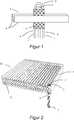
Gemäß verschiedenen Aspekten und Ausführungsformen, die hierin offenbart sind, wird eine Vorrichtung und ein Verfahren zum Sichern von Filtrationsmembranen in einem Filtrationssystem bereitgestellt. Die Filtrationsmembranen können Hohlfasermembranen sein. Die Hohlfasermembranen können in einer Falt- oder Schlaufenkonfiguration konfiguriert sein. Wie er hierin verwendet wird, bedeutet der Begriff der Schlaufenfaserkonfiguration eine, in der sich eine Faser von einem distalen Bereich zu einem proximalen Punkt erstreckt, zum Beispiel einem Punkt, bei dem sich ein Sicherungsmechanismus für die Faser befindet, und dann von dem proximalen Punkt zu dem distalen Bereich zurückkehrt. In einer Schlaufenfaserkonfiguration kann sich die Faser um den proximalen Punkt herum falten oder schleifen, um einen Schlaufenendabschnitt oder einen Augenabschnitt zu bilden. Längliche Abschnitte der Faser können sich von dem Schlaufenendabschnitt oder Augenabschnitt erstrecken. Schlaufenenden der Hohlfasermembranen können in einer Sicherungsvorrichtung mittels Reibung oder durch eine mechanische Haltestruktur oder -strukturen anstatt durch die Verwendung eines Haftmittels, beispielsweise eines Harzes oder Urethans, das als Eintopfmaterial in einem Membrantopf verwendet wird, gehalten werden. Die Sicherungsvorrichtung kann frei von Membransicherungshaftmitteln, beispielsweise Harze oder Urethane, sein. Die Verwendung einer mechanischen Struktur anstatt eines chemischen Haftstoffs zur Sicherung der Schlaufenenden der Hohlfasermembranen in einer Sicherungsvorrichtung kann die Möglichkeit eines mechanischen Versagens der Sicherungsvorrichtung aufgrund von beispielsweise Ablösung der Membranen von Membraneintopfmaterial oder Reißen des Eintopfmaterials reduzieren. Wie hierin verwendet, umfassen die Begriffe „mechanisch Eingreifen in“ und „mechanisches Stützen von“ Fasermembranen nicht chemisch oder haftend eingreifende oder sichernde Fasermembranen, zum Beispiel hinsichtlich eines Membraneintopfmaterials, und schließen diese aus.According to various aspects and embodiments disclosed herein, an apparatus and method for securing filtration membranes in a filtration system is provided. The filtration membranes may be hollow fiber membranes. The hollow fiber membranes may be configured in a fold or loop configuration. As used herein, the term loop fiber configuration means one in which a fiber extends from a distal region to a proximal point, for example a point at which there is a securing mechanism for the fiber, and then from the proximal point to returns to the distal area. In a loop fiber configuration, the fiber may fold or loop around the proximal point to form a loop end portion or an eye portion. Elongate portions of the fiber may extend from the loop end portion or eye portion. Loop ends of the hollow fiber membranes may be held in a securing device by friction or by a mechanical support structure or structures rather than by the use of an adhesive, for example a resin or urethane, used as a one-pot material in a diaphragm pot. The securing device may be free of membrane-securing adhesives, for example resins or urethanes. The use of a mechanical structure rather than a chemical adhesive to secure the loop ends of the hollow fiber membranes in a securing device can reduce the possibility of mechanical failure of the securing device due to, for example, detachment of membranes from membrane pot material or tearing of the one-pot material. As used herein, the terms "mechanically engaging" and "mechanically supporting" fiber membranes include and exclude non-chemically or adhesively engaging or securing fiber membranes, for example, with respect to a membrane well material.
Die offenen Enden der Hohlfasermembranen, beispielsweise mindestens ein offenes Ende jeder der Hohlfasermembranen, können in einem Membrantopf distal von der Sicherungsvorrichtung für die Schlaufenenden der Hohlfasermembranen gesichert sein. Filtrat kann von den offenen Enden der Hohlfasermembranen abgezogen werden.The open ends of the hollow fiber membranes, for example at least one open end of each of the hollow fiber membranes, may be secured in a diaphragm cup distal to the securing device for the loop ends of the hollow fiber membranes. Filtrate can be withdrawn from the open ends of the hollow fiber membranes.
Eine Vielzahl von Schlaufenhohlfasermembranen kann innerhalb einzelner modularer Sicherungsvorrichtungen gesichert werden. Eine Vielzahl von modularen Sicherungsvorrichtungen kann durch eine gemeinsame Stützstruktur oder einen gemeinsamen Rahmen gestützt werden und sie können mechanisch durch eine gemeinsame Stützstruktur aneinandergekoppelt sein. In manchen Ausführungsformen können einzelne modulare Sicherungsvorrichtungen und damit assoziierte Filtrationsmembranen in einem Filtrationssystem nach Wunsch entfernt oder ersetzt werden, ohne dass das gesamte Filtrationssystem außer Betrieb gesetzt werden muss. In manchen Ausführungsformen kann die Kapazität eines Filtrationssystems nach Wunsch erhöht werden, indem weitere modulare Sicherungsvorrichtungen und damit assoziierte Filtrationsmembranen hinzugefügt werden.A variety of looped hollow fiber membranes can be secured within individual modular securing devices. A variety of modular security devices may be supported by a common support structure or frame and may be mechanically coupled together by a common support structure. In some embodiments, individual modular backup devices and associated filtration membranes in a filtration system may be removed or replaced as desired without the need to shut down the entire filtration system. In some embodiments, the capacity of a filtration system may be increased as desired by adding more modular safety devices and filtration membranes associated therewith.
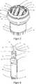
In manchen Ausführungsformen kann eine mechanische Sicherungsstruktur für Filtrationsmembranen eine Ankerformation umfassen, die durch die Anwendung einer mechanischen Kraft, beispielsweise einer Druckkraft, in die Filtrationsmembranen eingreift, an diese gesichert und/oder gekoppelt wird. In manchen Ausführungsformen kann zusätzlich zu einer Ankerformation eine Haltestruktur in einer Sicherungsvorrichtung verwendet werden. Die Haltestruktur kann die Membranen mechanisch sichern und/oder halten und/oder kann durch die Anwendung einer mechanischen Kraft, beispielsweise einer Druckkraft auf die Membranen, an die Membranen gekoppelt werden. Die Ankerformation und die Haltestruktur können an unterschiedliche Abschnitte der Filtrationsmembranen gekoppelt werden und/oder können an mindestens einen gemeinsamen Abschnitt der Filtrationsmembranen gekoppelt werden. Die Ankerformation und die Haltestruktur können aneinander gesichert werden oder ineinander eingreifen. Eine der Ankerformation und der Haltestruktur können mindestens teilweise auf einer äußeren Fläche der anderen angeordnet sein. Eine der Ankerformation und der Haltestruktur können mindestens teilweise von der anderen umgeben sein.In some embodiments, a filtration membrane mechanical securing structure may include an anchor formation that engages, is secured, and / or coupled to the filtration membranes by the application of a mechanical force, such as a compressive force. In some embodiments, in addition to an anchor formation, a support structure may be used in a securing device. The support structure may mechanically secure and / or retain the membranes and / or may be coupled to the membranes by the application of a mechanical force, such as a compressive force on the membranes. The anchor formation and the support structure may be coupled to different portions of the filtration membranes and / or may be coupled to at least a common portion of the filtration membranes. The anchor formation and the support structure can be secured to each other or intermesh. One of the anchor formation and the support structure may be at least partially disposed on an outer surface of the other. One of the anchor formation and the support structure may be at least partially surrounded by the other.
Unter Bezugnahme auf die Zeichnungen stellt
Die entgegengesetzten länglichen Teile
Die zylinderförmige Haltestruktur
Im Gebrauch kann ein Abschnitt der Haltestruktur
In manchen Ausführungsformen kann die Haltestruktur
Die Vielzahl von entgegengesetzten länglichen Teilen
Die vertikalen Durchgangslöcher
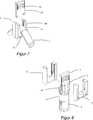
In
Der Kabelbinder
Die lösbare Hülse
Die Haltestruktur
Der umgekehrte U-förmige Clip
Die Haltestruktur
Es versteht sich, dass die Mittel zum Verbinden der Vielzahl von Vaterteil-Sperrstiften
Es versteht sich, dass die vorher beschriebenen Ausführungsformen der Ankerformationen
Es versteht sich, dass die vorher beschriebenen Ausführungsformen mit porösen Hohlmembranfasern
Nachdem somit verschiedene Aspekte mindestens einer Ausführungsform beschrieben worden sind, versteht es sich, dass dem Fachmann leicht verschiedene Änderungen, Abwandlungen und Verbesserungen einfallen werden. Es versteht sich, dass weitere Ausführungsformen und Veranschaulichungen möglich sind, ohne den Sinn und Bereich der Erfindung der Aspekte und Ausführungsformen, die beschrieben wurden, zu verlassen. Es ist beabsichtigt, dass derartige Änderungen, Abwandlungen und Verbesserungen Teil dieser Offenbarung sein sollen und innerhalb des Sinns und des Bereichs der offenbarten Aspekte und Ausführungsformen liegen sollen. Demgemäß sind die vorstehende Beschreibung und die Zeichnungen lediglich beispielhaft.Having thus described various aspects of at least one embodiment, it is to be understood that various changes, modifications, and improvements will readily occur to those skilled in the art. It should be understood that other embodiments and illustrations are possible without departing from the spirit and scope of the invention of the aspects and embodiments described. It is intended that such changes, modifications and improvements be part of this disclosure and be within the spirit and scope of the disclosed aspects and embodiments. Accordingly, the foregoing description and drawings are merely exemplary.
Claims (19)
Translated fromGermanApplications Claiming Priority (3)
| Application Number | Priority Date | Filing Date | Title |
|---|---|---|---|
| AU2012904196 | 2012-09-26 | ||
| AU2012904196AAU2012904196A0 (en) | 2012-09-26 | A securement device | |
| PCT/US2013/059927WO2014052071A1 (en) | 2012-09-26 | 2013-09-16 | Membrane securement device |
Publications (1)
| Publication Number | Publication Date |
|---|---|
| DE112013004713T5true DE112013004713T5 (en) | 2015-07-23 |
Family
ID=50388870
Family Applications (1)
| Application Number | Title | Priority Date | Filing Date |
|---|---|---|---|
| DE112013004713.6TPendingDE112013004713T5 (en) | 2012-09-26 | 2013-09-16 | Membrane safety device |
Country Status (6)
| Country | Link |
|---|---|
| US (1) | US9764289B2 (en) |
| CN (1) | CN104684631A (en) |
| AU (1) | AU2013324056B2 (en) |
| DE (1) | DE112013004713T5 (en) |
| GB (1) | GB2520871B (en) |
| WO (1) | WO2014052071A1 (en) |
Families Citing this family (4)
| Publication number | Priority date | Publication date | Assignee | Title |
|---|---|---|---|---|
| US20190282971A1 (en)* | 2018-03-15 | 2019-09-19 | Biotherm Hydronic, Inc. | Modular devices and systems for infusing gas into a liquid and methods of manufacture and use thereof |
| KR20210132921A (en)* | 2020-04-28 | 2021-11-05 | 주식회사 아모그린텍 | filter module for water-purifying device using gravity and water-purifying device including the same |
| AU2022272159A1 (en) | 2021-05-12 | 2023-11-09 | Ddp Specialty Electronic Materials Us, Llc | Multi-element filtration vessel |
| CN113975969B (en)* | 2021-12-28 | 2022-04-08 | 上海威德环保有限公司 | Detachable membrane module and disassembling method thereof |
Family Cites Families (889)
| Publication number | Priority date | Publication date | Assignee | Title |
|---|---|---|---|---|
| US511995A (en) | 1894-01-02 | Air and water purifier | ||
| US285321A (en) | 1883-09-18 | Pottery mold | ||
| US403507A (en) | 1889-05-21 | Petek j | ||
| US256008A (en) | 1882-04-04 | Posoelain and china paste boxes | ||
| US1997074A (en) | 1930-01-24 | 1935-04-09 | John Stogdell Stokes | Method of and apparatus for molding synthetic resinous articles |
| US2080783A (en) | 1932-03-09 | 1937-05-18 | Celluloid Corp | Method of molding thermoplastic materials |
| US2105700A (en) | 1936-07-13 | 1938-01-18 | William D Ramage | Process for purification of beverages |
| US2732357A (en) | 1949-11-25 | 1956-01-24 | Suspensions of polymeric chlorotri- | |
| US2843038A (en) | 1954-01-06 | 1958-07-15 | Robert O Manspeaker | Bakery apparatus and method |
| US2926086A (en) | 1957-07-30 | 1960-02-23 | Universal Oil Prod Co | Stabilization of non-distilled alcoholic beverages and the resulting product |
| US3068655A (en) | 1959-12-01 | 1962-12-18 | Standard Dredging Corp | Mobile pneumatic breakwater |
| US3183191A (en) | 1960-04-19 | 1965-05-11 | Hach Chemical Co | Stain and rust removing composition |
| NL269380A (en) | 1960-09-19 | |||
| GB996195A (en) | 1961-08-03 | 1965-06-23 | Aero Hydraulics Ltd | Improvements in methods and apparatus for mixing and dispersing substances and for maintaining dispersions and emulsions |
| US3139401A (en) | 1962-01-05 | 1964-06-30 | Hach Chemical Co | Method for removing rust from water softeners |
| US3198636A (en) | 1962-06-08 | 1965-08-03 | Norda Essential Oil And Chemic | Preservation of wine |
| US3246761A (en) | 1962-10-30 | 1966-04-19 | Bryan John Gordon | Liquid treating apparatus |
| US3191674A (en) | 1963-06-18 | 1965-06-29 | Westinghouse Electric Corp | Shell-and-tube type heat exchangers |
| NL296139A (en) | 1963-08-02 | |||
| NL136034C (en) | 1965-12-22 | |||
| US3492698A (en) | 1965-12-22 | 1970-02-03 | Du Pont | Centrifugal casting apparatus for forming a cast wall member extending transversely across an elongated bundle of substantially parallel hollow filaments of a fluid permeation separation apparatus |
| US3462362A (en) | 1966-07-26 | 1969-08-19 | Paul Kollsman | Method of reverse osmosis |
| DE1642833A1 (en) | 1967-03-16 | 1971-04-29 | Yves Henderyckx | Method and device for separating one or more components from a solution |
| US3501798A (en) | 1967-04-15 | 1970-03-24 | Ennio Carraro | Electric polisher for smooth vertical walls,such as window glass |
| SE320270B (en) | 1967-11-04 | 1970-02-02 | Inoue Michiro | |
| US3556305A (en) | 1968-03-28 | 1971-01-19 | Amicon Corp | Composite membrane and process for making same |
| US3591010A (en) | 1968-06-10 | 1971-07-06 | Pall Corp | Filter having a microporous layer attached thereto |
| US3472765A (en) | 1968-06-10 | 1969-10-14 | Dorr Oliver Inc | Membrane separation in biological-reactor systems |
| US3625827A (en) | 1968-09-27 | 1971-12-07 | Monsanto Co | Water-soluble polymer-enzyme products |
| US3505215A (en) | 1968-10-10 | 1970-04-07 | Desalination Systems | Method of treatment of liquids by reverse osmosis |
| US3628775A (en) | 1969-02-14 | 1971-12-21 | Atara Corp | Sewage-treating system |
| CH511629A (en) | 1969-03-27 | 1971-08-31 | Brasco Sa | Device for filtering a pressurized fluid |
| US3700561A (en) | 1969-08-11 | 1972-10-24 | Pabst Brewing Co | Recovery of enzymes |
| US3592450A (en) | 1969-12-03 | 1971-07-13 | George Maxwell Rippon | Fluid circulator |
| US3693406A (en) | 1970-01-26 | 1972-09-26 | Air Intake Renu | Method for inspecting filters |
| US3708071A (en) | 1970-08-05 | 1973-01-02 | Abcor Inc | Hollow fiber membrane device and method of fabricating same |
| US3700591A (en) | 1970-09-24 | 1972-10-24 | Us Interior | Cleaning of used membrane with oxalic acid |
| US3654147A (en) | 1971-03-16 | 1972-04-04 | Biospherics Inc | Nitrate removal from sewage |
| US3728256A (en) | 1971-06-22 | 1973-04-17 | Abcor Inc | Crossflow capillary dialyzer |
| US3763055A (en) | 1971-07-07 | 1973-10-02 | Us Interior | Microporous support for reverse osmosis membranes |
| GB1412983A (en) | 1971-11-30 | 1975-11-05 | Debell & Richardson | Method of producing porous plastic materials |
| US3795609A (en) | 1971-12-28 | 1974-03-05 | Administrator Environmental Pr | Reverse osmosis-neutralization process for treating mineral contaminated waters |
| US3791631A (en) | 1972-02-17 | 1974-02-12 | Mm Ind Inc | Method and apparatus for making colored expanded foam articles |
| US3804258A (en) | 1972-08-08 | 1974-04-16 | V Okuniewski | Filtering device |
| US3843809A (en) | 1972-08-23 | 1974-10-22 | E Luck | Manufacture of alcoholic beverages |
| US3937015A (en) | 1973-05-03 | 1976-02-10 | Nippondenso Co., Ltd. | Pleated filter in the exhaust manifold |
| US3955998A (en) | 1973-06-21 | 1976-05-11 | Phillips Petroleum Company | Aqueous gels for plugging fractures in subterranean formation and production of said aqueous gels |
| US3962095A (en) | 1973-06-22 | 1976-06-08 | Sandoz Ltd. | Dialyser cartridge |
| FR2236537B1 (en) | 1973-07-11 | 1977-12-23 | Rhone Poulenc Ind | |
| US3876738A (en) | 1973-07-18 | 1975-04-08 | Amf Inc | Process for producing microporous films and products |
| US3982095A (en) | 1973-10-04 | 1976-09-21 | Searle Cardio-Pulmonary Systems Inc. | Respiratory humidifier |
| US3992301A (en) | 1973-11-19 | 1976-11-16 | Raypak, Inc. | Automatic flushing system for membrane separation machines such as reverse osmosis machines |
| US3912624A (en) | 1974-03-26 | 1975-10-14 | Universal Oil Prod Co | Cleaning of membrane surfaces |
| US3968192A (en) | 1974-04-19 | 1976-07-06 | The Dow Chemical Company | Method of repairing leaky hollow fiber permeability separatory devices |
| US4016078A (en) | 1975-03-06 | 1977-04-05 | The Dow Chemical Company | Header block for tubular membrane permeator modules |
| JPS51128880A (en)* | 1975-05-02 | 1976-11-10 | Nippon Zeon Co | Method of securing yarn bundle end to case |
| US4105731A (en) | 1975-05-02 | 1978-08-08 | Nippon Zeon Co., Ltd. | Method of embedding an end of a bundle of thread-like bodies in a molding material and controlling capillary action by said material |
| IT1040274B (en) | 1975-07-30 | 1979-12-20 | Consiglio Nazionale Ricerche | PROCEDURE FOR PREPARATION OF ANISOTROPIC MEMBRANES SUPPORTED FOR REVERSE OSMOSIS BASED ON SYNTHETIC POLYAMIDES |
| GB1496805A (en) | 1975-09-19 | 1978-01-05 | Unilever Ltd | Dithionite composition |
| JPS5278677A (en) | 1975-12-25 | 1977-07-02 | Hitachi Ltd | Separation of membrane |
| US4105556A (en) | 1976-02-18 | 1978-08-08 | Combustion Engineering, Inc. | Liquid waste processing system |
| JPS535077A (en) | 1976-07-06 | 1978-01-18 | Nourinshiyou Shiyokuhin Sougou | Membrane separation method |
| US4192750A (en) | 1976-08-09 | 1980-03-11 | Massey-Ferguson Inc. | Stackable filter head unit |
| US4247498A (en) | 1976-08-30 | 1981-01-27 | Akzona Incorporated | Methods for making microporous products |
| US4107043A (en) | 1977-03-03 | 1978-08-15 | Creative Dispensing Systems, Inc. | Inlet conduit fluid filter |
| US4169873A (en) | 1976-12-13 | 1979-10-02 | Aero-Hydraulics Corporation | Fluid circulating device |
| US4130622A (en) | 1977-02-22 | 1978-12-19 | Abbott Laboratories | Method of making self-supporting tubular filter |
| JPS53108882A (en) | 1977-03-04 | 1978-09-22 | Kuraray Co Ltd | Back washing method for hollow filament membrane |
| US4203848A (en) | 1977-05-25 | 1980-05-20 | Millipore Corporation | Processes of making a porous membrane material from polyvinylidene fluoride, and products |
| US4138460A (en) | 1977-06-10 | 1979-02-06 | Cordis Dow Corp. | Method for forming tubesheets on hollow fiber tows and forming hollow fiber bundle assemblies containing same |
| US4519909A (en) | 1977-07-11 | 1985-05-28 | Akzona Incorporated | Microporous products |
| JPS6025194B2 (en) | 1977-08-04 | 1985-06-17 | 株式会社クラレ | centrifugal gluing device |
| US4157899A (en) | 1977-10-11 | 1979-06-12 | Cea Carter-Day Company | Pulsed backflush air filter |
| US4183890A (en) | 1977-11-30 | 1980-01-15 | Monsanto Company | Method of cutting hollow filaments embedded in resinous mass |
| US4204961A (en) | 1978-03-15 | 1980-05-27 | Cusato John Jr | Filter apparatus with cleaning function |
| US4193780A (en) | 1978-03-20 | 1980-03-18 | Industrial Air, Inc. | Air filter construction |
| US4227295A (en) | 1978-07-27 | 1980-10-14 | Baxter Travenol Laboratories, Inc. | Method of potting the ends of a bundle of hollow fibers positioned in a casing |
| FR2420548A1 (en) | 1978-03-25 | 1979-10-19 | Akzo Nv | POLYURETHANES COATING MASS, ITS PREPARATION PROCESS AND ITS USE |
| NZ190436A (en) | 1978-05-15 | 1981-12-15 | Pall Corp | Preparation of skinless hydrophilic alcohol insoluble polyamide membranes membranes casting resin solutions |
| US4315819A (en) | 1978-06-12 | 1982-02-16 | Monsanto Company | Hollow fiber permeator apparatus |
| JPS54162684A (en) | 1978-06-14 | 1979-12-24 | Ebara Infilco Co Ltd | Preliminary treating method for contaminated membrane |
| JPS5535910A (en) | 1978-09-06 | 1980-03-13 | Teijin Ltd | Permselectivity composite membrane and preparation thereof |
| SE447633B (en) | 1978-09-19 | 1986-12-01 | Albany Int Corp | PROCEDURE FOR SEPARATION AND MODULE FOR IMPLEMENTATION OF THE PROCEDURE |
| US4190419A (en) | 1978-09-22 | 1980-02-26 | Miles Laboratories, Inc. | Device for detecting serum bilirubin |
| DE7829409U1 (en) | 1978-10-02 | 1986-07-31 | Akzo Gmbh, 5600 Wuppertal | Dialysis membrane hollow thread with a larger exchange surface |
| US4188817A (en) | 1978-10-04 | 1980-02-19 | Standard Oil Company (Indiana) | Method for detecting membrane leakage |
| JPS5554004A (en) | 1978-10-18 | 1980-04-21 | Teijin Ltd | Selective permeable membrane and its manufacturing |
| US4367139A (en) | 1978-11-16 | 1983-01-04 | Monsanto Company | Hollow fiber permeator |
| DE2964867D1 (en) | 1978-12-06 | 1983-03-24 | Abcor Inc | Hydrophilic polymeric membranes, process for their preparation, their use as ultrafiltration membranes, and precursor membranes adapted to be converted thereto |
| US4187263A (en) | 1979-01-15 | 1980-02-05 | Aero-Hydraulics Corporation | Liquid circulating device |
| JPS5599703A (en) | 1979-01-26 | 1980-07-30 | Matsushita Electric Ind Co Ltd | Preparation of anisotropic resin magnet |
| BE874961A (en) | 1979-03-20 | 1979-09-20 | Studiecentrum Kernenergi | PROCESS FOR PREPARING A MEMBRANE, THEREFORE PREPARED MEMBRANE, ELECTROCHEMICAL CELL WITH SUCH MEMBRANE AND USING SUCH ELECTROchemical cell |
| JPS55129155A (en) | 1979-03-28 | 1980-10-06 | Sakai Chem Ind Co Ltd | Production of catalyst |
| JPS55129107A (en) | 1979-03-28 | 1980-10-06 | Nitto Electric Ind Co Ltd | Washing method of selective permeable membrane |
| US4243525A (en) | 1979-03-29 | 1981-01-06 | Fmc Corporation | Method for reducing the formation of trihalomethanes in drinking water |
| DE2915730C2 (en) | 1979-04-19 | 1987-04-23 | Kronsbein, Dirk-Gustav, 4000 Düsseldorf | Cartridge filter |
| US4218324A (en) | 1979-05-03 | 1980-08-19 | Textron, Inc. | Filter element having removable filter media member |
| US4226921A (en) | 1979-07-16 | 1980-10-07 | The Dow Chemical Company | Selective plugging of broken fibers in tubesheet-hollow fiber assemblies |
| US4248648A (en) | 1979-07-18 | 1981-02-03 | Baxter Travenol Laboratories, Inc. | Method of repairing leaks in a hollow capillary fiber diffusion device |
| JPS5621604A (en) | 1979-07-27 | 1981-02-28 | Toray Ind Inc | Separation of liquid by semipermeable composite membrane |
| US4271026A (en) | 1979-10-09 | 1981-06-02 | Air Products And Chemicals, Inc. | Control of activated sludge wastewater treating process for enhanced phosphorous removal |
| CA1115433A (en) | 1979-10-26 | 1981-12-29 | David C.I. Pollock | Method for protecting a bioreactor pressurized head tank against extreme surges of influent waste water |
| US4367140A (en) | 1979-11-05 | 1983-01-04 | Sykes Ocean Water Ltd. | Reverse osmosis liquid purification apparatus |
| JPS5695304A (en) | 1979-12-28 | 1981-08-01 | Teijin Ltd | Perm selective composite membrane and its production |
| US4323453A (en) | 1980-01-03 | 1982-04-06 | Monsanto Company | Tube sheets for permeators |
| JPS5944884B2 (en) | 1980-02-26 | 1984-11-01 | 株式会社クラレ | Hollow fiber end sealing method and device |
| JPS56121685A (en) | 1980-02-29 | 1981-09-24 | Ebara Infilco Co Ltd | Treatment of liquid containing iron ion and manganese ion |
| US4629563B1 (en) | 1980-03-14 | 1997-06-03 | Memtec North America | Asymmetric membranes |
| US4369605A (en) | 1980-07-11 | 1983-01-25 | Monsanto Company | Methods for preparing tube sheets for permeators having hollow fiber membranes |
| JPS5735907A (en) | 1980-07-15 | 1982-02-26 | Toyobo Co Ltd | Fluid separating element |
| DE3026718A1 (en) | 1980-07-15 | 1982-02-04 | Akzo Gmbh, 5600 Wuppertal | HOLLOW FIBER MEMBRANE FOR PLASMA SEPARATION |
| US4889620A (en) | 1980-09-29 | 1989-12-26 | Water Pollution Control Corporation | In place gas cleaning of diffusion elements |
| US4384474A (en) | 1980-10-30 | 1983-05-24 | Amf Incorporated | Method and apparatus for testing and using membrane filters in an on site of use housing |
| US4389363A (en) | 1980-11-03 | 1983-06-21 | Baxter Travenol Laboratories, Inc. | Method of potting microporous hollow fiber bundles |
| DK146709C (en) | 1980-12-09 | 1984-05-21 | Eskesen Brdr As | PROCEDURE FOR MANUFACTURING INJECTIVE PLASTIC SUBSTANCES WITH INSERT SHEETS WITH DECORATIVE AND / OR DESCRIPTIVE PRESSURE AND APPLIANCES FOR USE IN EXERCISING THE PROCEDURE |
| JPS57102202A (en) | 1980-12-18 | 1982-06-25 | Toyobo Co Ltd | Fluid separator |
| US4496470A (en) | 1981-01-12 | 1985-01-29 | The B. F. Goodrich Company | Cleaning composition |
| US4545862A (en) | 1981-03-17 | 1985-10-08 | W. L. Gore & Associates, Inc. | Desalination device and process |
| JPS57190697A (en) | 1981-05-18 | 1982-11-24 | Serupoole Kogyo Kk | Air diffusion apparatus |
| JPS6059933B2 (en) | 1981-05-22 | 1985-12-27 | 工業技術院長 | Polymer membrane with maleic anhydride residues |
| US4371427A (en) | 1981-06-16 | 1983-02-01 | Phillips Petroleum Company | Extractive distillation |
| JPS5888007A (en) | 1981-11-20 | 1983-05-26 | Asahi Glass Co Ltd | How to separate liquid mixtures |
| US4702840A (en) | 1982-02-05 | 1987-10-27 | Pall Corporation | Charge modified polyamide membrane |
| US4707266A (en) | 1982-02-05 | 1987-11-17 | Pall Corporation | Polyamide membrane with controlled surface properties |
| US4405688A (en) | 1982-02-18 | 1983-09-20 | Celanese Corporation | Microporous hollow fiber and process and apparatus for preparing such fiber |
| US4415452A (en) | 1982-03-18 | 1983-11-15 | Heil Richard W | Method and apparatus for treating organic wastewater |
| US4812235A (en) | 1982-03-29 | 1989-03-14 | Hr Textron, Inc. | Filter element assembly replaceable mesh pack |
| EP0090383B1 (en) | 1982-03-29 | 1990-05-23 | Hr Textron Inc. | Filter element assembly replaceable mesh pack |
| US4540490A (en) | 1982-04-23 | 1985-09-10 | Jgc Corporation | Apparatus for filtration of a suspension |
| US4431545A (en) | 1982-05-07 | 1984-02-14 | Pall Corporation | Microporous filter system and process |
| US4476112A (en) | 1982-05-10 | 1984-10-09 | Stay Fresh, Inc. | Food preservative composition |
| WO1983003984A1 (en) | 1982-05-13 | 1983-11-24 | Gerhard Kunz | Method for the treatment of a liquid phase, particularly method for desalting aqueous solutions, as well as device for its implementation |
| US4414172A (en) | 1982-05-21 | 1983-11-08 | Filtertek, Inc. | Process and apparatus for sealing a plurality of filter elements |
| JPS5952507A (en) | 1982-06-03 | 1984-03-27 | デ−・エル・エム・ドクトル・ミユラ−・アクチエンゲゼルシヤフト | Apparatus for continuously concentrating suspension |
| US4462855A (en) | 1982-06-28 | 1984-07-31 | Celanese Corporation | Process for bonding polyester reinforcement elements to rubber |
| JPS5928971A (en) | 1982-08-06 | 1984-02-15 | 川澄化学工業株式会社 | Hollow yarn type mass transfer apparatus and production thereof |
| US4414113A (en) | 1982-09-29 | 1983-11-08 | Ecodyne Corporation | Liquid purification using reverse osmosis hollow fibers |
| US4476015A (en) | 1982-11-02 | 1984-10-09 | V. J. Ciccone & Associates, Inc. | Multiple element fluid separation device |
| JPS5992094A (en) | 1982-11-18 | 1984-05-28 | Agency Of Ind Science & Technol | Anaerobic digestion of organic waste matter |
| GB2132366B (en) | 1982-12-27 | 1987-04-08 | Brunswick Corp | Method and device for testing the permeability of membrane filters |
| US4467001A (en) | 1982-12-27 | 1984-08-21 | Albany International Corp. | Process and device for applying, drying and curing a coating on filaments |
| CA1221645A (en) | 1983-02-28 | 1987-05-12 | Yoshihiro Okano | Filtration apparatus using hollow fiber-membrane |
| DE3317396A1 (en) | 1983-05-13 | 1984-11-15 | Henkel KGaA, 4000 Düsseldorf | USE OF COLOYERS FROM ESTERS AND AMIDES OF ACRYLIC AND / OR METHACRYLIC ACIDS AS STOCK POINTS LOW FOR PARAFFIN SOLUTIONS |
| GB8313635D0 (en) | 1983-05-17 | 1983-06-22 | Whatman Reeve Angel Plc | Porosimeter |
| CH673275A5 (en) | 1983-05-20 | 1990-02-28 | Christ Ag | |
| JPH0657302B2 (en) | 1983-07-13 | 1994-08-03 | 株式会社東芝 | Backwashing method for hollow fiber membrane filters |
| US4636296A (en) | 1983-08-18 | 1987-01-13 | Gerhard Kunz | Process and apparatus for treatment of fluids, particularly desalinization of aqueous solutions |
| US4650586A (en) | 1983-09-26 | 1987-03-17 | Kinetico, Inc. | Fluid treatment system |
| US4756875A (en) | 1983-09-29 | 1988-07-12 | Kabushiki Kaisha Toshiba | Apparatus for filtering water containing radioactive substances in nuclear power plants |
| JPH0659393B2 (en) | 1983-09-30 | 1994-08-10 | メムテツク リミテツド | Filter cleaning method |
| US4888115A (en) | 1983-12-29 | 1989-12-19 | Cuno, Incorporated | Cross-flow filtration |
| JPS60206412A (en) | 1984-03-28 | 1985-10-18 | Nitto Electric Ind Co Ltd | End face repair method for hollow fiber membrane separation module |
| WO1985004593A1 (en) | 1984-04-11 | 1985-10-24 | Syrinx Research Pty. Ltd. | High flux membrane |
| JPS60176300U (en) | 1984-04-23 | 1985-11-21 | 海洋工業株式会社 | water pump |
| US4539940A (en) | 1984-04-26 | 1985-09-10 | Young Richard K | Tube and shell heat exchanger with annular distributor |
| US4609465A (en) | 1984-05-21 | 1986-09-02 | Pall Corporation | Filter cartridge with a connector seal |
| JPS60260628A (en) | 1984-06-08 | 1985-12-23 | Idemitsu Petrochem Co Ltd | Thermoplastic resin molding coated with plasma polymer film |
| SE441236B (en) | 1984-06-18 | 1985-09-23 | Gambro Dialysatoren | PROCEDURE FOR MANUFACTURING A DEVICE CONTAINING A HALFIBER BUNCH |
| EP0170895B1 (en) | 1984-07-09 | 1989-03-22 | Millipore Corporation | Improved electrodeionization apparatus and method |
| JPS6125903U (en) | 1984-07-24 | 1986-02-15 | 株式会社 伊藤鉄工所 | filtration equipment |
| DE3428307A1 (en) | 1984-08-01 | 1986-02-13 | Filterwerk Mann & Hummel Gmbh, 7140 Ludwigsburg | DISPLAY DEVICE FOR THE POLLUTION LEVEL OF SUCTION AIR FILTERS |
| JPS6197006A (en) | 1984-10-18 | 1986-05-15 | Daicel Chem Ind Ltd | Repairing method of hollow yarn type module |
| JPS6197005A (en) | 1984-10-18 | 1986-05-15 | Mitsubishi Rayon Co Ltd | Manufacturing method of hollow fiber membrane module |
| US5192478A (en) | 1984-10-22 | 1993-03-09 | The Dow Chemical Company | Method of forming tubesheet for hollow fibers |
| JPS61107905A (en) | 1984-10-30 | 1986-05-26 | Toshiba Corp | filter |
| US5198162A (en) | 1984-12-19 | 1993-03-30 | Scimat Limited | Microporous films |
| GB2168981B (en) | 1984-12-27 | 1988-07-06 | Asahi Chemical Ind | Porous fluorine resin membrane and process for preparation thereof |
| JPS61167406A (en) | 1985-01-19 | 1986-07-29 | Sumitomo Bakelite Co Ltd | Process for bundling and fixing separation membrane |
| JPS61167407A (en) | 1985-01-19 | 1986-07-29 | Sumitomo Bakelite Co Ltd | Preparation of hollow yarn filtration membrane module |
| JPS61171504A (en) | 1985-01-25 | 1986-08-02 | Agency Of Ind Science & Technol | Apparatus for centrifugal molding of yarn bundle |
| JPS61192309A (en) | 1985-02-21 | 1986-08-26 | Asahi Chem Ind Co Ltd | Hollow fiber module |
| JPH0667459B2 (en) | 1985-03-05 | 1994-08-31 | メムテック・リミテッド | Method and device for concentrating fine solids in suspension |
| US5024762A (en) | 1985-03-05 | 1991-06-18 | Memtec Limited | Concentration of solids in a suspension |
| US4642182A (en) | 1985-03-07 | 1987-02-10 | Mordeki Drori | Multiple-disc type filter with extensible support |
| JPS61222510A (en) | 1985-03-28 | 1986-10-03 | Nitto Electric Ind Co Ltd | Hollow yarn membrane module and its preparation |
| EP0216876B1 (en) | 1985-03-28 | 1990-05-16 | Memtec Limited | Cooling hollow fibre cross-flow separators |
| US4704324A (en) | 1985-04-03 | 1987-11-03 | The Dow Chemical Company | Semi-permeable membranes prepared via reaction of cationic groups with nucleophilic groups |
| JPS62502452A (en) | 1985-04-10 | 1987-09-24 | メムテック・リミテッド | Variable volume filter or concentrator |
| JPS61242607A (en) | 1985-04-22 | 1986-10-28 | Asahi Chem Ind Co Ltd | Preparation of hollow yarn type module having slit |
| US4610789A (en) | 1985-04-22 | 1986-09-09 | Ppg Industries, Inc. | Filtration cartridge and reactor |
| JPS61249505A (en) | 1985-04-27 | 1986-11-06 | Toyobo Co Ltd | Method for preserving fluid separator |
| CA1247329A (en) | 1985-05-06 | 1988-12-28 | Craig J. Brown | Fluid treatment process and apparatus |
| JPS61257203A (en) | 1985-05-10 | 1986-11-14 | Terumo Corp | Hydrophilic porous membrane and its preparation |
| JPS61263605A (en) | 1985-05-17 | 1986-11-21 | Toshiba Corp | Hollow yarn membrane device |
| JPS61274709A (en) | 1985-05-29 | 1986-12-04 | Ebara Corp | Hollow yarn membrane filter apparatus |
| US4660411A (en) | 1985-05-31 | 1987-04-28 | Reid Philip L | Apparatus for measuring transmission of volatile substances through films |
| JPS61291007A (en) | 1985-06-17 | 1986-12-20 | Toyobo Co Ltd | Hollow yarn type separation membrane element |
| JPS61293504A (en) | 1985-06-24 | 1986-12-24 | Kurita Water Ind Ltd | Separation device utilizing hollow yarn membrane |
| JPS624408A (en) | 1985-06-28 | 1987-01-10 | Toshiba Corp | Hollow fiber membrane filtration device |
| DE3529175A1 (en) | 1985-08-14 | 1987-02-19 | Gft Ingenieurbuero | DEVICE FOR SEPARATING MIXED MEANS OF THE PERVAPORATION METHOD |
| US4656865A (en) | 1985-09-09 | 1987-04-14 | The Dow Chemical Company | System for analyzing permeation of a gas or vapor through a film or membrane |
| JPS6268828A (en) | 1985-09-19 | 1987-03-28 | Youbea Le-Ron Kogyo Kk | Transparent cassette liner |
| US4908114A (en) | 1985-09-27 | 1990-03-13 | William Ayers | Mobile atom insertion reaction, mobile atom transmissive membrane for carrying out the reaction, and reactor incorporating the mobile atom transmissive membrane |
| US4876006A (en) | 1985-10-08 | 1989-10-24 | Ebara Corporation | Hollow fiber filter device |
| JPS62114609A (en) | 1985-11-15 | 1987-05-26 | Ebara Corp | Hollow yarn membrane filter |
| US4824563A (en) | 1985-12-04 | 1989-04-25 | Kabushiki Kaisha Meidensha | Equipment for treating waste water |
| US4687578A (en) | 1985-12-12 | 1987-08-18 | Monsanto Company | Fluid separation membranes |
| JPH0613088B2 (en) | 1985-12-13 | 1994-02-23 | ダイセル化学工業株式会社 | Aseptic leak detection method for hollow fiber type modules |
| JPS62144708A (en) | 1985-12-19 | 1987-06-27 | Daicel Chem Ind Ltd | Hollow yarn mold membrane module |
| DE3546091A1 (en) | 1985-12-24 | 1987-07-02 | Kernforschungsz Karlsruhe | CROSS-CURRENT MICROFILTER |
| JPS62163708A (en) | 1986-01-13 | 1987-07-20 | Ebara Corp | Method for backwashing hollow yarn filter |
| US4779448A (en) | 1986-01-28 | 1988-10-25 | Donaldson Company, Inc. | Photoelectric bubble detector apparatus and method |
| JPH06104753B2 (en) | 1986-02-04 | 1994-12-21 | 旭化成工業株式会社 | Non-adsorbing hydrophilic hollow fiber porous membrane |
| JPS62187606A (en) | 1986-02-14 | 1987-08-17 | Toshiba Corp | Running vehicle |
| JPH0742861B2 (en) | 1986-03-10 | 1995-05-15 | ヤマハ発動機株式会社 | Internal combustion engine intake system |
| US4752421A (en) | 1986-04-01 | 1988-06-21 | Kaiyo Kogyo Kabushiki Kaisha | Method of supplying air masses and producing jets of water |
| JPS62237908A (en) | 1986-04-07 | 1987-10-17 | Kurita Water Ind Ltd | Filter module for hollow yarn type membrane separation equipment |
| JPS62250908A (en) | 1986-04-24 | 1987-10-31 | Asahi Chem Ind Co Ltd | Hollow yarn type filter |
| US4774132A (en) | 1986-05-01 | 1988-09-27 | Pall Corporation | Polyvinylidene difluoride structure |
| JPH0741147B2 (en) | 1986-05-09 | 1995-05-10 | 株式会社東芝 | Hollow fiber membrane filtration device |
| DE3617724A1 (en) | 1986-05-27 | 1987-12-03 | Akzo Gmbh | METHOD FOR DETERMINING THE BLOW POINT OR THE BIGGEST PORE OF MEMBRANES OR FILTER MATERIALS |
| JPS631602A (en) | 1986-06-19 | 1988-01-06 | Nippon Filing Co Ltd | Material storage system |
| FR2600265B1 (en) | 1986-06-20 | 1991-09-06 | Rhone Poulenc Rech | DRY AND HYDROPHILIC SEMI-PERMEABLE MEMBRANES BASED ON VINYLIDENE POLYFLUORIDE |
| FR2601182B1 (en) | 1986-07-07 | 1992-01-24 | Electricite De France | PROCESS FOR THE RADIOACTIVE DECONTAMINATION OF A LUBRICANT |
| US4670145A (en) | 1986-07-08 | 1987-06-02 | E. I. Du Pont De Nemours And Company | Multiple bundle fluid separation apparatus |
| US4839048A (en) | 1986-07-08 | 1989-06-13 | Pall Corporation | Container for pressurized fluid |
| ES2014516A6 (en) | 1986-07-11 | 1990-07-16 | Mentec Ltd | Cleaning of filters. |
| JPS6338884A (en) | 1986-07-30 | 1988-02-19 | 大同特殊鋼株式会社 | Thermal treatment equipment |
| AU605187B2 (en) | 1986-09-04 | 1991-01-10 | Memtec Limited | Cleaning of hollow fibre filters |
| US5094750A (en) | 1986-09-12 | 1992-03-10 | Memtec Limited | Hollow fibre filter cartridge and header |
| JPS6393307A (en) | 1986-10-09 | 1988-04-23 | Asahi Chem Ind Co Ltd | Hollow yarn-type filter |
| JPH089668B2 (en) | 1986-10-14 | 1996-01-31 | 東レ株式会社 | Hydrophilized film and method for producing the same |
| DE3636583A1 (en) | 1986-10-28 | 1988-05-05 | Draegerwerk Ag | METHOD FOR PRODUCING A HOLLOW FIBER FABRIC EXCHANGE MODULE AND MODULE PRODUCED BY THIS METHOD |
| JPS63143905A (en) | 1986-12-08 | 1988-06-16 | Toshiba Corp | Hollow fiber membrane filter |
| US4781831A (en) | 1986-12-19 | 1988-11-01 | Goldsmith Robert L | Cross-flow filtration device with filtrate flow conduits and method of forming same |
| US4834998A (en) | 1986-12-22 | 1989-05-30 | Heublein, Inc. | Ultrafiltration of red wines |
| JPS63171607A (en) | 1986-12-30 | 1988-07-15 | Sumitomo Electric Ind Ltd | How to seal the ends of hollow fiber membranes |
| KR940002379B1 (en) | 1987-01-20 | 1994-03-24 | 데루모 가부시끼가이샤 | Polypropylene porous membrane and its manufacturing method |
| JPS63180254A (en) | 1987-01-21 | 1988-07-25 | Matsushita Electric Ind Co Ltd | private branch exchange |
| CN1004400B (en) | 1987-01-27 | 1989-06-07 | 东北电力学院 | Media filtration method and apparatus |
| US4911838A (en) | 1987-02-27 | 1990-03-27 | Kabushiki Kobe Seiko Sho | Pluri-tubular aerator |
| US4867883A (en) | 1987-04-21 | 1989-09-19 | Hampton Roads Sanitation District Of The Commonwealth Of Virginia | High-rate biological waste water treatment process using activated sludge recycle |
| US4846970A (en) | 1987-06-22 | 1989-07-11 | Osmonics, Inc. | Cross-flow filtration membrane test unit |
| DE3878899T2 (en) | 1987-07-30 | 1993-07-22 | Toray Industries | POROESE POLYTETRAFLUORAETHYLENE MEMBRANE, SEPARATING DEVICE USING THIS MEMBRANE AND METHOD FOR THE PRODUCTION THEREOF. |
| JPS6438197A (en) | 1987-07-31 | 1989-02-08 | Nishihara Env San Res Co Ltd | Treatment of sewage |
| US4784771A (en) | 1987-08-03 | 1988-11-15 | Environmental Water Technology, Inc. | Method and apparatus for purifying fluids |
| JPH0627215B2 (en) | 1987-09-17 | 1994-04-13 | テルモ株式会社 | Method for producing hydrophilic polyvinylidene fluoride porous membrane |
| JPH01144409A (en) | 1987-09-18 | 1989-06-06 | Pennwalt Corp | Hydrophylic sequence copolymer of vinylidene fluoride and n-alkylacrylamide and its production |
| JPH0610277B2 (en) | 1987-09-28 | 1994-02-09 | ジャパンゴアテックス株式会社 | Membrane material |
| JPH01151906A (en) | 1987-12-08 | 1989-06-14 | Ube Ind Ltd | Manufacturing method of hollow fiber membrane module cartridge |
| DE3803341A1 (en) | 1988-02-04 | 1989-08-10 | Sartorius Gmbh | FLUID-OPEN-ENDING SITES HAVING POROESE MEMBRANE FILTERS AND THEIR USE |
| US5221478A (en) | 1988-02-05 | 1993-06-22 | The Dow Chemical Company | Chromatographic separation using ion-exchange resins |
| GB8807825D0 (en) | 1988-03-31 | 1988-05-05 | Romicon Inc | Multiple membrane filtration systems |
| US5227101A (en) | 1988-03-31 | 1993-07-13 | The Dow Chemical Company | Process of making microporous membranes from poly(etheretherketone)-type polymers and low melting point crystallizable polymers |
| US4904426A (en) | 1988-03-31 | 1990-02-27 | The Dow Chemical Company | Process for the production of fibers from poly(etheretherketone)-type polymers |
| DE3824359A1 (en) | 1988-04-07 | 1989-10-19 | Bayer Ag | COMPOSITE MEMBRANES, METHOD FOR THEIR PRODUCTION AND THEIR USE |
| US4800019A (en) | 1988-04-22 | 1989-01-24 | Union Carbide Corporation | Tubesheet for semipermeable membrane devices |
| US5147553A (en) | 1988-05-04 | 1992-09-15 | Ionics, Incorporated | Selectively permeable barriers |
| US4966699A (en) | 1988-05-25 | 1990-10-30 | Terumo Kabushiki Kaisha | Hollow fiber membrane fluid processor |
| US4886601A (en) | 1988-05-31 | 1989-12-12 | Japan Organo Co., Ltd. | Column filter using bundles of long fibers |
| JP2527462B2 (en) | 1988-06-03 | 1996-08-21 | ダイセル化学工業株式会社 | Hollow fiber ultrafiltration membrane module automatic leak detection and alarm system |
| JPH0217924A (en) | 1988-07-04 | 1990-01-22 | Toshiba Corp | Backwashing method for hollow fiber membrane filtration equipment |
| JPH0217925A (en) | 1988-07-07 | 1990-01-22 | Toshiba Corp | Backwash method for hollow fiber membrane filtration equipment |
| JP2830080B2 (en) | 1988-07-08 | 1998-12-02 | 株式会社デンソー | Filter element and manufacturing method thereof |
| JPH0226625A (en) | 1988-07-14 | 1990-01-29 | Toshiba Corp | Back washing method of hollow fiber membrane filter |
| JPH0760197B2 (en) | 1988-07-21 | 1995-06-28 | 株式会社荏原製作所 | Backwashing method for hollow fiber membrane filters |
| JPH0240296A (en) | 1988-07-30 | 1990-02-09 | Nippon Sharyo Seizo Kaisha Ltd | Apparatus and method for treating waste water |
| US5075065A (en) | 1988-08-01 | 1991-12-24 | Chemical Fabrics Corporation | Method for manufacturing of cast films at high productivity |
| US5043113A (en) | 1988-08-05 | 1991-08-27 | Hoechst Celanese Corp. | Process for formation of halogenated polymeric microporous membranes having improved strength properties |
| DE3829766A1 (en) | 1988-09-01 | 1990-03-22 | Akzo Gmbh | METHOD FOR PRODUCING MEMBRANES |
| US4963304A (en) | 1988-09-26 | 1990-10-16 | The Dow Chemical Company | Process for preparing microporous membranes |
| JP2529726B2 (en) | 1988-10-14 | 1996-09-04 | ダイセル化学工業株式会社 | Hollow fiber type membrane module |
| JPH02126922A (en) | 1988-11-04 | 1990-05-15 | Mitsui Eng & Shipbuild Co Ltd | Back washing method of separating membrane |
| FR2639248B1 (en) | 1988-11-21 | 1990-12-28 | Lyonnaise Eaux | HOUSING FOR FILTER MODULES WITH FIBER BEAMS |
| JPH02144132A (en) | 1988-11-25 | 1990-06-01 | Mitsubishi Rayon Co Ltd | porous polyolefin film |
| JPH0671540B2 (en) | 1988-12-20 | 1994-09-14 | 株式会社東芝 | Cleaning method of hollow fiber membrane filter |
| JPH0657304B2 (en) | 1988-12-27 | 1994-08-03 | 三浦工業株式会社 | Membrane modular water treatment system |
| US4919815A (en) | 1989-02-06 | 1990-04-24 | Zimpro/Passavant Inc. | Two-stage anaerobic/aerobic treatment process |
| US4999038A (en) | 1989-02-07 | 1991-03-12 | Lundberg Bo E H | Filter unit |
| DE3904544A1 (en) | 1989-02-15 | 1990-08-16 | Fraunhofer Ges Forschung | POLYMINE MEMBRANES BASED ON POLYVINYLIDENE FLUORIDE, METHOD FOR THE PRODUCTION AND USE THEREOF |
| US4952317A (en) | 1989-03-10 | 1990-08-28 | Bradley Culkin | Device and method for filtering a colloidal suspension |
| JPH02241523A (en) | 1989-03-16 | 1990-09-26 | Sumitomo Bakelite Co Ltd | Hollow yarn membrane module |
| JP2856763B2 (en) | 1989-04-20 | 1999-02-10 | 株式会社東芝 | Backwashing device for hollow fiber membrane filter |
| JP2773231B2 (en) | 1989-04-25 | 1998-07-09 | 東洋紡績株式会社 | Leak test method for hydrophobic hollow fiber type porous membrane |
| NL8901090A (en) | 1989-04-28 | 1990-11-16 | X Flow Bv | METHOD FOR MANUFACTURING A MICROPOROUS MEMBRANE AND SUCH MEMBRANE |
| US4988444A (en) | 1989-05-12 | 1991-01-29 | E. I. Du Pont De Nemours And Company | Prevention of biofouling of reverse osmosis membranes |
| US5005430A (en) | 1989-05-16 | 1991-04-09 | Electric Power Research Institute, Inc. | Automated membrane filter sampler |
| DE3916511A1 (en) | 1989-05-20 | 1990-12-13 | Seitz Filter Werke | MEMBRANE FILTER DEVICE FOR MICRO AND ULTRAFILTRATION OF FLUIDS IN THE CROSSFLOW PROCESS |
| JPH0318373A (en) | 1989-06-16 | 1991-01-25 | Terumo Corp | Method and device for detecting leak of hollow fiber membrane type liquid processor |
| JPH0736039B2 (en) | 1989-06-27 | 1995-04-19 | 株式会社荏原製作所 | Method for removing suspended impurities from condensate by mixed bed condensate desalination system |
| US5138870A (en) | 1989-07-10 | 1992-08-18 | Lyssy Georges H | Apparatus for measuring water vapor permeability through sheet materials |
| DE3923128A1 (en) | 1989-07-13 | 1991-01-24 | Akzo Gmbh | FLAX OR CAPILLARY MEMBRANE BASED ON A HOMOGENEOUS MIXTURE OF POLYVINYLIDE FLUORIDE AND OF A SECOND, BY CHEMICAL IMPROVEMENT, HYDROPHILIBLABLE POLYMERS |
| US5015275A (en) | 1989-07-14 | 1991-05-14 | The Dow Chemical Company | Isotropic microporous syndiotactic polystyrene membranes and processes for preparing the same |
| DE3926059C2 (en) | 1989-08-07 | 1998-01-29 | Basf Ag | Phosphonomethylated polyvinylamines, process for their preparation and their use |
| JPH0645185B2 (en) | 1989-08-30 | 1994-06-15 | ユニチカ株式会社 | Porous composite sheet and method for producing the same |
| US5080770A (en) | 1989-09-11 | 1992-01-14 | Culkin Joseph B | Apparatus and method for separating particles |
| JPH03110445A (en) | 1989-09-25 | 1991-05-10 | Fuji Photo Film Co Ltd | Completeness testing method |
| US5059317A (en) | 1989-10-02 | 1991-10-22 | Dietrich Marius | Transportable apparatus for producing drinking water |
| US5227063A (en) | 1989-10-03 | 1993-07-13 | Zenon Environmental Inc. | Tubular membrane module |
| EP0519132A1 (en) | 1989-10-18 | 1992-12-23 | Exxon Research And Engineering Company | Hollow fiber module |
| US5158721A (en) | 1989-11-30 | 1992-10-27 | Millipore Corporation | Porous membrane formed from interpenetrating polymer network having hydrophilic surface |
| US5079272A (en) | 1989-11-30 | 1992-01-07 | Millipore Corporation | Porous membrane formed from interpenetrating polymer network having hydrophilic surface |
| FR2655642B1 (en) | 1989-12-11 | 1992-02-28 | Anjou Rech | WATER TREATMENT PLANT BY A TANGENTIAL FILTER LOOP. |
| DE3943249C2 (en) | 1989-12-29 | 1993-11-18 | Seitz Filter Werke | Closed filter element |
| DE4000978A1 (en) | 1990-01-16 | 1991-07-18 | Basf Ag | METHOD FOR REMOVING HEAVY METALIONS FROM WINE AND WINE-BASED BEVERAGES |
| US5458779A (en) | 1990-01-23 | 1995-10-17 | Kaldnes Miljoteknologi A/S | Method for purification of water |
| US5066375A (en) | 1990-03-19 | 1991-11-19 | Ionics, Incorporated | Introducing and removing ion-exchange and other particulates from an assembled electrodeionization stack |
| US5364527A (en) | 1990-06-20 | 1994-11-15 | Heinz Zimmermann | Apparatus and process for treating water |
| IT1242864B (en) | 1990-06-26 | 1994-05-18 | Perdomini Spa | AUTOMATIC CONTROL AND OPTIMIZATION SYSTEM OF ULTRAFILTRATION PROCEDURES IN INDUSTRIAL FOOD AND / OR CHEMICAL AND / OR CHEMICAL-PHARMACEUTICAL PLANTS AND ULTRAFILTRATION PROCEDURE USING SUCH SYSTEM. |
| DE4117281C2 (en) | 1990-06-29 | 1996-02-22 | Gore Enterprise Holdings Inc | Hydrophilized, microporous membrane made of polytetrafluoroethylene and process for its production |
| US5104546A (en) | 1990-07-03 | 1992-04-14 | Aluminum Company Of America | Pyrogens separations by ceramic ultrafiltration |
| US5639373A (en) | 1995-08-11 | 1997-06-17 | Zenon Environmental Inc. | Vertical skein of hollow fiber membranes and method of maintaining clean fiber surfaces while filtering a substrate to withdraw a permeate |
| US5104535A (en)* | 1990-08-17 | 1992-04-14 | Zenon Environmental, Inc. | Frameless array of hollow fiber membranes and module containing a stack of arrays |
| US5182019A (en) | 1990-08-17 | 1993-01-26 | Zenon Environmental Inc. | Cartridge of hybrid frameless arrays of hollow fiber membranes and module containing an assembly of cartridges |
| FR2666245B1 (en) | 1990-08-31 | 1992-10-23 | Lyonnaise Eaux | METHOD FOR CONTROLLING THE OPERATING MODES OF AN AUTOMATIC WATER FILTRATION APPARATUS ON TUBULAR MEMBRANES. |
| JP2904564B2 (en) | 1990-08-31 | 1999-06-14 | オルガノ株式会社 | Method of scrubbing filtration tower using hollow fiber membrane |
| JP2858913B2 (en) | 1990-09-26 | 1999-02-17 | オルガノ株式会社 | Filtration method using hollow fiber membrane |
| US5102550A (en) | 1990-11-01 | 1992-04-07 | The United States Of America As Represented By The Secretary Of The Navy | Apparatus and process for desalination of seawater |
| USH1045H (en) | 1990-11-19 | 1992-05-05 | The United States Of America As Represented By The Secretary Of The Army | Air bubble leak detection test device |
| JPH04187224A (en) | 1990-11-20 | 1992-07-03 | Mitsubishi Rayon Co Ltd | Manufacturing method of fluorine-based porous hollow fiber membrane |
| JPH0815597B2 (en) | 1990-11-22 | 1996-02-21 | 株式会社クボタ | Operating method of sewage treatment equipment |
| US5176953A (en) | 1990-12-21 | 1993-01-05 | Amoco Corporation | Oriented polymeric microporous films |
| JPH04250898A (en) | 1990-12-28 | 1992-09-07 | Yanmar Diesel Engine Co Ltd | Batch-wise waste water treating device |
| US5069065A (en) | 1991-01-16 | 1991-12-03 | Mobil Oil Corporation | Method for measuring wettability of porous rock |
| JP2706853B2 (en) | 1991-01-16 | 1998-01-28 | ハウス食品株式会社 | Membrane filter integrity inspection method and inspection device |
| JPH04256425A (en) | 1991-02-05 | 1992-09-11 | Nippon Millipore Kogyo Kk | Backwash device for filtration |
| JPH04256424A (en) | 1991-02-06 | 1992-09-11 | Nitto Denko Corp | Hollow fiber membrane module |
| GB2253572B (en) | 1991-02-11 | 1994-12-14 | Aljac Engineering Limited | Flow device in fluid circuits |
| US5677360A (en) | 1991-02-13 | 1997-10-14 | Mitsubishi Rayon Co., Ltd. | Hydrophilic polymer alloy, fiber and porous membrane comprising this polymer alloy, and methods for preparing them |
| JPH084722B2 (en) | 1991-02-20 | 1996-01-24 | 株式会社荏原製作所 | Membrane separation device |
| DK0510328T3 (en) | 1991-03-07 | 1996-02-05 | Kubota Kk | Apparatus for treating activated sludge |
| JP3115624B2 (en) | 1991-03-20 | 2000-12-11 | ダイセル化学工業株式会社 | Hollow fiber membrane module and method of manufacturing the same |
| FR2674448B1 (en) | 1991-03-26 | 1994-03-25 | Dumez Lyonnaise Eaux | METHOD FOR CLEANING MESOPOROUS TUBULAR MEMBRANES OF ULTRAFILTRATION. |
| JP3093811B2 (en) | 1991-04-08 | 2000-10-03 | 旭化成工業株式会社 | Polyvinylidene fluoride resin film and method for producing the same |
| JPH04317793A (en) | 1991-04-17 | 1992-11-09 | Kubota Corp | water treatment equipment |
| EP0509152A1 (en) | 1991-04-17 | 1992-10-21 | Ecotechniek B.V. | Method and apparatus for processing manure |
| DE4113420A1 (en) | 1991-04-25 | 1992-10-29 | Bayer Ag | Hollow polyacrylonitrile fibres, useful for membrane processes - mfd. by dry-wet or wet spinning from special spinning solns. contg. PAN and non-solvent etc., with simultaneous extrusion of core fluid |
| CA2109436C (en) | 1991-05-01 | 2002-02-05 | Level Valley Dairy Company | Wastewater treatment system |
| JPH04334530A (en) | 1991-05-10 | 1992-11-20 | Kubota Corp | Filter apparatus |
| DE4117422C1 (en) | 1991-05-28 | 1992-11-12 | Willi Prof. Dr.-Ing. 7432 Bad Urach De Dettinger | Monitoring contamination level of filter, partic. for hydraulic fluids - in which signal is produced which correlates with quotient of two pressure differences and evaluating device produces signal to change filter when quotient reaches given value |
| DE4119040C2 (en) | 1991-06-10 | 1997-01-02 | Pall Corp | Method and device for testing the operating state of filter elements |
| US5211823A (en) | 1991-06-19 | 1993-05-18 | Millipore Corporation | Process for purifying resins utilizing bipolar interface |
| TW216773B (en) | 1991-06-21 | 1993-12-01 | Johnson Filtration Systems | |
| US5156738A (en) | 1991-06-21 | 1992-10-20 | Johnson Filtration Systems Inc. | Apparatus for uniformly distributing gas and/or liquid in an underdrain lateral system |
| JP2659475B2 (en) | 1991-06-27 | 1997-09-30 | 株式会社クボタ | Solid-liquid separator |
| JP3200095B2 (en) | 1991-07-24 | 2001-08-20 | 旭化成株式会社 | Hydrophilic heat-resistant film and method for producing the same |
| DE69230766T2 (en) | 1991-08-07 | 2000-08-31 | Usf Filtration Ltd., South Windsor | CONCENTRATION OF SOLIDS IN A SLUDGE USING CARBON FIBER MEMBRANES |
| US5186821A (en) | 1991-09-03 | 1993-02-16 | D. Thomas Murphy | Wastewater treatment process with cooperating velocity equalization, aeration and decanting means |
| US5211728A (en)* | 1991-09-30 | 1993-05-18 | The Dow Chemical Company | Clamshell retainer used in hollow fiber membrane devices |
| JP2622044B2 (en) | 1991-10-04 | 1997-06-18 | 東レ株式会社 | Hollow fiber membrane module and method of using the same |
| US5135663A (en) | 1991-10-18 | 1992-08-04 | Loctite Corporation | Method of treating (meth)acrylic monomer-containing wastewater |
| US5137631A (en) | 1991-10-22 | 1992-08-11 | E. I. Du Pont De Nemours And Company | Multiple bundle permeator |
| US5180407A (en) | 1991-11-14 | 1993-01-19 | Demarco Thomas M | Vacuum loader with vaned and short tangential separator |
| JPH05137977A (en) | 1991-11-15 | 1993-06-01 | Kubota Corp | Membrane filtration device separation membrane damage detection method |
| US5192442A (en) | 1991-12-02 | 1993-03-09 | Zimpro Passavant Environmental Systems, Inc. | Multiple zone batch treatment process |
| JP3111101B2 (en) | 1991-12-03 | 2000-11-20 | 旭化成工業株式会社 | Leak inspection method for membrane separation equipment |
| JPH05161831A (en) | 1991-12-16 | 1993-06-29 | Mitsubishi Kasei Corp | Hollow yarn membrane module and separation method using the same |
| TW207964B (en) | 1991-12-16 | 1993-06-21 | Permea Inc | |
| WO1993013489A1 (en) | 1991-12-24 | 1993-07-08 | Sierra Semiconductor Corporation | An anti-aliasing method for polynomial curves using integer arithmetics |
| JPH05184884A (en) | 1992-01-08 | 1993-07-27 | Mitsubishi Rayon Co Ltd | Method for backwashing hollow fiber membrane module |
| US5269919A (en) | 1992-01-17 | 1993-12-14 | Von Medlin Wallace | Self-contained water treatment system |
| US5556591A (en) | 1992-01-21 | 1996-09-17 | Millipore S.A. | Membrane sealing techniques using thermoplastic polymers |
| US5203405A (en) | 1992-02-03 | 1993-04-20 | Phillips Petroleum Company | Two pass shell and tube heat exchanger with return annular distributor |
| US5198116A (en) | 1992-02-10 | 1993-03-30 | D.W. Walker & Associates | Method and apparatus for measuring the fouling potential of membrane system feeds |
| FR2697446B1 (en) | 1992-11-03 | 1994-12-02 | Aquasource | Process for the treatment of a fluid containing suspended and dissolved materials, using separation membranes. |
| US5411663A (en) | 1992-03-20 | 1995-05-02 | Micron Separations, Inc. | Alcohol-insoluble nylon microporous membranes |
| JPH05285348A (en) | 1992-04-04 | 1993-11-02 | Nitto Denko Corp | Vertical hollow fiber membrane module |
| JPH05305221A (en) | 1992-04-28 | 1993-11-19 | Toshiba Corp | Membrane separation water treatment apparatus |
| DE69313574T2 (en) | 1992-05-01 | 1998-01-08 | Filtec Corp | Device for checking the integrity of membrane filters |
| JPH0627215A (en) | 1992-07-08 | 1994-02-04 | Matsushita Electric Ind Co Ltd | Portable gps receiver |
| CA2100643A1 (en) | 1992-08-14 | 1994-02-15 | Guido Sartori | Fluorinated polyolefin membranes for aromatics/saturates separation |
| JPH0671120A (en) | 1992-08-27 | 1994-03-15 | Akai Electric Co Ltd | Method for detecting blinding of filter |
| MY109609A (en) | 1992-09-14 | 1997-03-31 | Dowmus Pty Ltd | Method and apparatus for disposal and treatment of waste |
| JP3250274B2 (en) | 1992-10-08 | 2002-01-28 | 東レ株式会社 | Filter |
| US5244579A (en) | 1992-10-09 | 1993-09-14 | Zenon Environmental Inc. | Transportable reverse osmosis water purification unit |
| US5275766A (en) | 1992-10-30 | 1994-01-04 | Corning Incorporate | Method for making semi-permeable polymer membranes |
| DE69329388T2 (en) | 1992-11-02 | 2001-01-04 | Usf Filtration Ltd., South Windsor | HOLLOW FIBER MODULE CONTROL SYSTEM |
| US5320760A (en) | 1992-12-07 | 1994-06-14 | E. I. Du Pont De Nemours And Company | Method of determining filter pluggage by measuring pressures |
| JPH06170364A (en) | 1992-12-07 | 1994-06-21 | Suido Kiko Kk | Filter by permeable membrane |
| FR2699424B1 (en) | 1992-12-21 | 1995-02-03 | Dumez Lyonnaise Eaux | Hollow fiber filtration module and its manufacturing process. |
| JPH06190250A (en) | 1992-12-25 | 1994-07-12 | Mitsubishi Rayon Co Ltd | Membrane module cleaning method |
| US5262054A (en) | 1992-12-30 | 1993-11-16 | E. I. Du Pont De Nemours And Company | Process for opening reverse osmosis membranes |
| US5401401A (en) | 1993-01-13 | 1995-03-28 | Aquaria Inc. | Hang on tank canister filter |
| US5316671A (en) | 1993-01-21 | 1994-05-31 | Murphy D Thomas | Submersible aeration train and aeration apparatus for biological purification of sewage |
| US5374353A (en) | 1993-01-21 | 1994-12-20 | Murphy; D. Thomas | Aeration train and aeration apparatus for biological purification of wastewater |
| JP3010951B2 (en) | 1993-01-25 | 2000-02-21 | 株式会社クボタ | Immersion filtration device |
| JPH06238273A (en) | 1993-02-17 | 1994-08-30 | Mitsubishi Rayon Eng Co Ltd | Membrane separation type water purification method |
| US5468397A (en) | 1993-03-16 | 1995-11-21 | Memtec America Corporation | Gas backwash of pleated filters |
| JP3289376B2 (en) | 1993-03-26 | 2002-06-04 | 栗田工業株式会社 | Membrane separation device |
| US5389260A (en) | 1993-04-02 | 1995-02-14 | Clack Corporation | Brine seal for tubular filter |
| JPH06285496A (en) | 1993-04-07 | 1994-10-11 | Ebara Infilco Co Ltd | Hollow fiber membrane separation biological treatment and device for organic drainage |
| JPH06292820A (en) | 1993-04-09 | 1994-10-21 | Kurita Water Ind Ltd | Membrane separation device |
| US5514278A (en) | 1993-04-12 | 1996-05-07 | Khudenko; Boris M. | Counterflow microbiological processes |
| US5361625A (en) | 1993-04-29 | 1994-11-08 | Ylvisaker Jon A | Method and device for the measurement of barrier properties of films against gases |
| US5297420A (en) | 1993-05-19 | 1994-03-29 | Mobil Oil Corporation | Apparatus and method for measuring relative permeability and capillary pressure of porous rock |
| US5401405A (en) | 1993-05-24 | 1995-03-28 | Davis Water & Waste Industries, Inc. | Combined air/water backwash in a travelling bridge filter |
| FR2705734B1 (en) | 1993-05-25 | 1995-06-30 | Snecma | Method and device for improving the safety of fluid filters. |
| IL105875A (en) | 1993-06-01 | 1998-04-05 | Aga Ab | Selective clogging of failed fibers |
| JPH09220569A (en) | 1993-06-02 | 1997-08-26 | Kubota Corp | Solid-liquid separator |
| JPH06343837A (en) | 1993-06-02 | 1994-12-20 | Ebara Infilco Co Ltd | Hollow fiber membrane module |
| US5425415A (en) | 1993-06-15 | 1995-06-20 | Abb Lummus Crest Inc. | Vertical heat exchanger |
| JP3273665B2 (en) | 1993-06-17 | 2002-04-08 | 株式会社東芝 | Hollow fiber membrane filtration device and cleaning method thereof |
| JP2946072B2 (en) | 1993-07-09 | 1999-09-06 | 三菱レイヨン株式会社 | Filtration method |
| JP3306794B2 (en) | 1993-07-30 | 2002-07-24 | 冨士ダイス株式会社 | Frame member and method of manufacturing the same |
| DE4326603C2 (en) | 1993-08-07 | 1995-11-02 | Kummer Karl Dankwart Dipl Ing | Sewage treatment plant with aeration tank, process for wastewater treatment |
| US5358732A (en) | 1993-08-10 | 1994-10-25 | Albert Einstein College Of Medicine Of Yeshiva University | Method and system for removing impurities from aliments |
| JPH07112185A (en) | 1993-08-26 | 1995-05-02 | Nitto Denko Corp | Wastewater treatment device and cleaning method thereof |
| JP2721787B2 (en) | 1993-09-06 | 1998-03-04 | 日本メムテック株式会社 | Backwashing method for hollow fiber membrane module |
| JP3342928B2 (en) | 1993-09-13 | 2002-11-11 | オルガノ株式会社 | Hanging equipment for filtration equipment using hollow fiber modules |
| US5419816A (en) | 1993-10-27 | 1995-05-30 | Halox Technologies Corporation | Electrolytic process and apparatus for the controlled oxidation of inorganic and organic species in aqueous solutions |
| JP3453173B2 (en) | 1993-11-12 | 2003-10-06 | 三菱レイヨン株式会社 | Hollow fiber membrane module with diffuser |
| JPH07136471A (en) | 1993-11-15 | 1995-05-30 | Toray Ind Inc | Hollow yarn membrane module |
| FR2713220B1 (en) | 1993-11-30 | 1996-03-08 | Omnium Traitement Valorisa | Installation of water purification with submerged filter membranes. |
| JPH07155758A (en) | 1993-12-07 | 1995-06-20 | Mitsubishi Rayon Co Ltd | Waste water treating device |
| JPH07155564A (en) | 1993-12-10 | 1995-06-20 | Mitsubishi Rayon Co Ltd | Hollow fiber membrane module and manufacturing method thereof |
| US5403479A (en) | 1993-12-20 | 1995-04-04 | Zenon Environmental Inc. | In situ cleaning system for fouled membranes |
| JP3160140B2 (en) | 1993-12-22 | 2001-04-23 | オルガノ株式会社 | Filtration device using hollow fiber module |
| JP3341428B2 (en) | 1993-12-24 | 2002-11-05 | 栗田工業株式会社 | Operating method of immersion membrane device |
| JP2763262B2 (en) | 1993-12-24 | 1998-06-11 | 日本碍子株式会社 | Backwashing method of ceramic membrane |
| JP3341427B2 (en) | 1993-12-24 | 2002-11-05 | 栗田工業株式会社 | Immersion membrane equipment |
| JPH07185268A (en) | 1993-12-28 | 1995-07-25 | Toray Ind Inc | Hollow fiber filter membrane element and module |
| JP3289457B2 (en) | 1993-12-28 | 2002-06-04 | 栗田工業株式会社 | Immersion membrane equipment |
| TW255835B (en) | 1994-01-07 | 1995-09-01 | Kubota Kk | Filtration membrane module |
| JPH07204635A (en) | 1994-01-21 | 1995-08-08 | I B Ii:Kk | Water purifier |
| JPH07251043A (en) | 1994-01-28 | 1995-10-03 | Toto Ltd | Filtering method and filter device |
| US6036030A (en) | 1994-02-02 | 2000-03-14 | Bechtel Bwxt Idaho Llc | Method for producing a selectively permeable separation module |
| JPH07236819A (en) | 1994-02-25 | 1995-09-12 | Nok Corp | Air bubble disperser |
| DK175061B1 (en) | 1994-03-02 | 2004-05-10 | Apv Pasilac As | Membrane filtration Event |
| DE4406952A1 (en) | 1994-03-03 | 1995-09-07 | Bayer Ag | Process for concentrating paint overspray |
| US5501798A (en) | 1994-04-06 | 1996-03-26 | Zenon Environmental, Inc. | Microfiltration enhanced reverse osmosis for water treatment |
| JP3486451B2 (en) | 1994-04-12 | 2004-01-13 | 三菱レイヨン株式会社 | Hollow fiber membrane module |
| JPH07289860A (en) | 1994-04-25 | 1995-11-07 | Toray Ind Inc | Cleaning method of hollow fiber membrane module |
| US5556541A (en) | 1994-04-26 | 1996-09-17 | Filtertek, Inc. | Process for making hermetically sealed filter units and filters made thereby |
| JPH07303895A (en) | 1994-05-16 | 1995-11-21 | Kubota Corp | Water treatment equipment |
| JP3396085B2 (en) | 1994-05-24 | 2003-04-14 | テルモ株式会社 | Hollow fiber membrane type blood processor |
| JP3697719B2 (en) | 1994-05-26 | 2005-09-21 | 松下電工株式会社 | Water purifier and method for cleaning porous filtration membrane in water purifier |
| JPH07313850A (en) | 1994-05-30 | 1995-12-05 | Kubota Corp | Immersion type ceramic membrane separator backwash method |
| CN2204898Y (en) | 1994-06-29 | 1995-08-09 | 鹿乔 | Proportional flow controlling valve |
| JP3094407B2 (en) | 1994-06-29 | 2000-10-03 | 株式会社石垣 | Concentrator using hollow fiber membrane |
| US5531900A (en) | 1994-07-07 | 1996-07-02 | University Of Arizona | Modification of polyvinylidene fluoride membrane and method of filtering |
| US5846425A (en) | 1994-07-22 | 1998-12-08 | Whiteman; George R. | Methods for treatment of waste streams |
| JPH0839089A (en) | 1994-08-02 | 1996-02-13 | Toto Ltd | Purifying tank and operation thereof |
| US5451317A (en) | 1994-09-08 | 1995-09-19 | Kubota Corporation | Solid-liquid separator |
| US5470469A (en) | 1994-09-16 | 1995-11-28 | E. I. Du Pont De Nemours And Company | Hollow fiber cartridge |
| FR2726568B1 (en) | 1994-11-08 | 1996-12-06 | Atochem Elf Sa | POLYMER MIXTURES COMPRISING A HALOGEN POLYMER AND COMPATIBILIZED BY A GRAFT ALIPHATIC POLYESTER |
| AUPM957194A0 (en) | 1994-11-18 | 1994-12-15 | Act Electricity & Water | Wastewater treatment method and plant |
| CN2236049Y (en) | 1994-12-01 | 1996-09-25 | 张利军 | Three-way stop valve |
| JP3194684B2 (en) | 1995-01-27 | 2001-07-30 | ダイセル化学工業株式会社 | Natural water membrane purification method |
| DE19503060A1 (en) | 1995-02-01 | 1996-08-08 | Henkel Ecolab Gmbh & Co Ohg | Cleaning procedure for membrane filters |
| AU700335B2 (en) | 1995-03-22 | 1998-12-24 | Mechano Chemical Research Institute Ltd. | Method for desalinating salts-containing water and apparatus therefor |
| TW283657B (en) | 1995-03-31 | 1996-08-21 | Mitsui Eng & Shipbuilding Co | Membrane device and its processing device |
| US5597732A (en) | 1995-04-14 | 1997-01-28 | Bryan-Brown; Michael | Composting apparatus |
| US6001254A (en) | 1995-04-14 | 1999-12-14 | Aquasource | Method of operating and monitoring a group of filter membrane modules, and a group of modules implementing the method |
| JP3446399B2 (en) | 1995-05-31 | 2003-09-16 | 日立プラント建設株式会社 | Immersion type membrane separation device and membrane separation method using the same |
| JPH08332357A (en) | 1995-06-06 | 1996-12-17 | Toray Ind Inc | Method and apparatus for regenerating filter module |
| EP0773753B1 (en) | 1995-06-07 | 2003-10-08 | Gore Hybrid Technologies, Inc. | An implantable containment apparatus for a therapeutical device |
| JPH09890A (en) | 1995-06-21 | 1997-01-07 | Mitsubishi Kakoki Kaisha Ltd | Flat membrane separation device |
| US5906742A (en) | 1995-07-05 | 1999-05-25 | Usf Filtration And Separations Group Inc. | Microfiltration membranes having high pore density and mixed isotropic and anisotropic structure |
| JP3349015B2 (en) | 1995-07-25 | 2002-11-20 | 株式会社日立製作所 | Filtration device |
| JPH0938648A (en) | 1995-08-02 | 1997-02-10 | Japan Organo Co Ltd | Treatment of blow water of power plant |
| US5766479A (en) | 1995-08-07 | 1998-06-16 | Zenon Environmental Inc. | Production of high purity water using reverse osmosis |
| US5670053A (en) | 1995-08-07 | 1997-09-23 | Zenon Environmental, Inc. | Purification of gases from water using reverse osmosis |
| US6685832B2 (en) | 1995-08-11 | 2004-02-03 | Zenon Environmental Inc. | Method of potting hollow fiber membranes |
| DE69632422T2 (en) | 1995-08-11 | 2005-05-19 | Zenon Environmental Inc., Oakville | Process for embedding hollow fiber membranes |
| US6193890B1 (en) | 1995-08-11 | 2001-02-27 | Zenon Environmental Inc. | System for maintaining a clean skein of hollow fibers while filtering suspended solids |
| US7087173B2 (en) | 1995-08-11 | 2006-08-08 | Zenon Environmental Inc. | Inverted cavity aerator for membrane module |
| US6863823B2 (en) | 2001-03-23 | 2005-03-08 | Zenon Environmental Inc. | Inverted air box aerator and aeration method for immersed membrane |
| US6656356B2 (en) | 1998-10-09 | 2003-12-02 | Zenon Environmental Inc. | Aerated immersed membrane system |
| US5944997A (en) | 1995-08-11 | 1999-08-31 | Zenon Environmental Inc. | System for maintaining a clean skein of hollow fibers while filtering suspended solids |
| JP3137568B2 (en) | 1995-09-07 | 2001-02-26 | オルガノ株式会社 | Method of scrubbing filtration tower using hollow fiber membrane |
| JPH0975682A (en) | 1995-09-13 | 1997-03-25 | Kanegafuchi Chem Ind Co Ltd | Hollow fiber membrane integrated module |
| JP3583201B2 (en) | 1995-09-14 | 2004-11-04 | 三菱レイヨン株式会社 | Cleaning method for separation membrane module |
| JP3294979B2 (en) | 1995-09-14 | 2002-06-24 | 株式会社精工技研 | Optical fiber ferrule assembly with angle index indicating direction of polarization plane of optical fiber |
| WO1997010893A1 (en) | 1995-09-21 | 1997-03-27 | Asahi Kasei Kogyo Kabushiki Kaisha | Hollow fiber membrane module |
| JP3671473B2 (en) | 1995-10-05 | 2005-07-13 | 栗田工業株式会社 | Immersion membrane separator |
| JP3671477B2 (en) | 1995-10-12 | 2005-07-13 | 栗田工業株式会社 | Cleaning method for submerged membrane separator |
| JPH09103655A (en) | 1995-10-13 | 1997-04-22 | Kanegafuchi Chem Ind Co Ltd | Hollow fiber membrane filter |
| RU2119817C1 (en) | 1995-10-23 | 1998-10-10 | Акционерное общество открытого типа "Полимерсинтез" | Porous fluorocarbon membrane, method of its preparation, and cartridge filter based on this membrane |
| JPH09117647A (en) | 1995-10-24 | 1997-05-06 | Kubota Corp | How to operate the air diffuser |
| JPH09187628A (en) | 1995-10-31 | 1997-07-22 | Nikkiso Co Ltd | Hollow fiber type module and manufacturing method thereof |
| US5626755A (en) | 1995-11-08 | 1997-05-06 | Micronair, Inc. | Method and apparatus for waste digestion using multiple biological processes |
| JPH09138298A (en) | 1995-11-16 | 1997-05-27 | Hitachi Ltd | Filtration device using hollow fiber membrane and backwashing method thereof |
| JPH09141063A (en) | 1995-11-21 | 1997-06-03 | Mitsubishi Rayon Co Ltd | Hollow fiber membrane module |
| FR2741280B1 (en) | 1995-11-22 | 1997-12-19 | Omnium Traitement Valorisa | METHOD FOR CLEANING A FILTER SYSTEM OF THE SUBMERSIBLE MEMBRANE TYPE |
| US5744037A (en) | 1995-11-28 | 1998-04-28 | Ebara Corporation | Method of treating foul water |
| JPH09155345A (en) | 1995-12-01 | 1997-06-17 | Hitachi Plant Eng & Constr Co Ltd | Hollow fiber membrane module filtration method |
| JPH09192458A (en) | 1996-01-22 | 1997-07-29 | Nok Corp | Hollow yarn membrane module |
| US6074718A (en) | 1996-02-06 | 2000-06-13 | Koch Membrane Systems, Inc. | Self supporting hollow fiber membrane and method of construction |
| US5895570A (en) | 1996-02-09 | 1999-04-20 | United States Filter Corporation | Modular filtering system |
| US6077435A (en) | 1996-03-15 | 2000-06-20 | Usf Filtration And Separations Group Inc. | Filtration monitoring and control system |
| JPH09271641A (en) | 1996-04-04 | 1997-10-21 | Kanegafuchi Chem Ind Co Ltd | Production of hollow yarn membrane module |
| JPH09313902A (en) | 1996-05-28 | 1997-12-09 | Kubota Corp | Chemical cleaning method for immersion ceramic membrane separator |
| JPH09324067A (en) | 1996-06-05 | 1997-12-16 | Shin Etsu Polymer Co Ltd | Method for producing fluororesin porous body |
| EP0814116A1 (en) | 1996-06-19 | 1997-12-29 | Hüls Aktiengesellschaft | Hydrophilic coating of polymeric substrate surfaces |
| US5989428A (en) | 1996-06-21 | 1999-11-23 | Goronszy; Mervyn Charles | Controlling wastewater treatment by monitoring oxygen utilization rates |
| EP0813897A3 (en) | 1996-06-21 | 1998-06-24 | Japan Pionics Co., Ltd. | Dust removing apparatus and dust removing method |
| JP3198923B2 (en) | 1996-07-04 | 2001-08-13 | 栗田工業株式会社 | Cleaning method of membrane |
| US5958243A (en) | 1996-07-11 | 1999-09-28 | Zenon Environmental Inc. | Apparatus and method for membrane filtration with enhanced net flux |
| JP3248611B2 (en) | 1996-07-12 | 2002-01-21 | 日立プラント建設株式会社 | Solid-liquid separation device |
| JPH1033955A (en) | 1996-07-23 | 1998-02-10 | Hitachi Zosen Corp | Membrane separation device |
| JP3278577B2 (en) | 1996-07-31 | 2002-04-30 | セイコーインスツルメンツ株式会社 | Adhesive for optical connector and ferrule and optical connector using the same |
| US5814234A (en) | 1996-08-14 | 1998-09-29 | Prosys Corporation | Integrated soil and fluid decontamination system |
| US5866001A (en) | 1996-08-21 | 1999-02-02 | Essef Corporation | Filament wound housing for a reverse osmosis filter cartridge |
| JPH10110657A (en) | 1996-08-22 | 1998-04-28 | Stanadyne Automot Corp | Filter assembly having matching cartridge support structure |
| JPH1066972A (en) | 1996-08-28 | 1998-03-10 | Nomura Micro Sci Co Ltd | Cleaning and regenerating method of separation membrane for water treatment |
| JPH1076264A (en) | 1996-09-05 | 1998-03-24 | Kubota Corp | Sewage treatment equipment using immersion type membrane separation equipment |
| JPH1076144A (en) | 1996-09-05 | 1998-03-24 | Kurita Water Ind Ltd | Membrane separation device using hollow tubular membrane |
| US5786528A (en) | 1996-09-10 | 1998-07-28 | Millipore Corporation | Water intrusion test for filters |
| JPH1085566A (en) | 1996-09-11 | 1998-04-07 | Hitachi Ltd | Pleated filtration device |
| US5888401A (en) | 1996-09-16 | 1999-03-30 | Union Camp Corporation | Method and apparatus for reducing membrane fouling |
| JPH1085562A (en) | 1996-09-17 | 1998-04-07 | Asahi Chem Ind Co Ltd | Union restricting orifice and filtration device |
| JPH1085565A (en) | 1996-09-19 | 1998-04-07 | Yamada Kogyo Kk | Membrane separator |
| JP3686918B2 (en) | 1996-10-16 | 2005-08-24 | 森村興産株式会社 | Filtration device for solid-liquid separation of sewage, wastewater, etc. |
| USD396046S (en) | 1996-10-24 | 1998-07-14 | Allen Scheel | Steer device for an outboard motor |
| AUPO377796A0 (en) | 1996-11-21 | 1996-12-19 | Memtec America Corporation | Microporous membrane filtration and backwashing process |
| JP3436026B2 (en) | 1996-12-02 | 2003-08-11 | エヌオーケー株式会社 | Hollow fiber membrane module |
| AUPO412596A0 (en) | 1996-12-10 | 1997-01-09 | Memtec America Corporation | Improved microporous membrane filtration assembly |
| AT407291B (en) | 1996-12-12 | 2001-02-26 | Andreas Weissenbacher | THREE-WAY VALVE |
| US6045899A (en) | 1996-12-12 | 2000-04-04 | Usf Filtration & Separations Group, Inc. | Highly assymetric, hydrophilic, microfiltration membranes having large pore diameters |
| US20040232076A1 (en) | 1996-12-20 | 2004-11-25 | Fufang Zha | Scouring method |
| ES2353254T3 (en) | 1996-12-20 | 2011-02-28 | Siemens Water Technologies Corp. | WASHING PROCEDURE |
| WO1998028064A1 (en) | 1996-12-21 | 1998-07-02 | Akzo Nobel Nv | Membrane module with hollow fibre membranes arranged in layers |
| JPH10180048A (en) | 1996-12-27 | 1998-07-07 | Kurita Water Ind Ltd | Immersion type membrane separation device |
| DE19700493A1 (en) | 1997-01-09 | 1998-07-16 | Bayer Ag | Methods for cleaning surfaces |
| US6146747A (en) | 1997-01-22 | 2000-11-14 | Usf Filtration And Separations Group Inc. | Highly porous polyvinylidene difluoride membranes |
| USD396726S (en) | 1997-02-06 | 1998-08-04 | Abc Group | Combined air intake manifold and filter |
| JP3887072B2 (en) | 1997-02-12 | 2007-02-28 | 株式会社クラレ | Method for cleaning hollow fiber membrane module and filtration device used in the method |
| JPH10225685A (en) | 1997-02-17 | 1998-08-25 | Hitachi Ltd | Water purification equipment |
| JPH10235168A (en) | 1997-02-24 | 1998-09-08 | Mitsubishi Rayon Co Ltd | How to clean the filter |
| US6120688A (en) | 1997-02-25 | 2000-09-19 | Zenon Environmental, Inc. | Portable reverse osmosis unit for producing drinking water |
| US6007712A (en) | 1997-02-28 | 1999-12-28 | Kuraray Co., Ltd. | Waste water treatment apparatus |
| US6048454A (en) | 1997-03-18 | 2000-04-11 | Jenkins; Dan | Oil filter pack and assembly |
| JPH10249171A (en) | 1997-03-18 | 1998-09-22 | Kanegafuchi Chem Ind Co Ltd | Hollow yarn membrane module |
| US5733456A (en) | 1997-03-31 | 1998-03-31 | Okey; Robert W. | Environmental control for biological nutrient removal in water/wastewater treatment |
| FR2762834B1 (en) | 1997-05-05 | 1999-06-04 | Ete Europ De Traitement Des Ea | PROCESS AND PLANT FOR THE TREATMENT OF WASTEWATER AND THEIR APPLICATION TO WINE EFFLUENTS |
| JP2945894B2 (en) | 1997-05-16 | 1999-09-06 | 日本碍子株式会社 | How to remove cleaning chemicals |
| JPH10328538A (en) | 1997-05-29 | 1998-12-15 | Japan Organo Co Ltd | Method for cleaning hollow yarn membrane filtration tower |
| AUPO709797A0 (en) | 1997-05-30 | 1997-06-26 | Usf Filtration And Separations Group Inc. | Predicting logarithmic reduction values |
| JP3859816B2 (en) | 1997-06-16 | 2006-12-20 | 三菱レイヨン株式会社 | Hollow fiber membrane filtration device |
| JPH1111494A (en) | 1997-06-19 | 1999-01-19 | Takako Hashimoto | Bag assembly |
| NL1006390C2 (en) | 1997-06-25 | 1998-12-29 | Triqua B V | Cross=flow filtration process |
| US5914039A (en) | 1997-07-01 | 1999-06-22 | Zenon Environmental Inc. | Filtration membrane with calcined α-alumina particles therein |
| US6354444B1 (en) | 1997-07-01 | 2002-03-12 | Zenon Environmental Inc. | Hollow fiber membrane and braided tubular support therefor |
| JPH1128467A (en) | 1997-07-08 | 1999-02-02 | Nkk Corp | Immersion type membrane separation device |
| JPH1131025A (en) | 1997-07-11 | 1999-02-02 | Ricoh Co Ltd | PC card slot |
| JPH1133365A (en) | 1997-07-17 | 1999-02-09 | Asahi Chem Ind Co Ltd | Method and apparatus for two-layer centrifugal bonding of hollow yarn membrane module |
| JPH1133367A (en) | 1997-07-24 | 1999-02-09 | Mitsubishi Rayon Co Ltd | Hollow fiber membrane module |
| UA61961C2 (en) | 1997-07-29 | 2003-12-15 | A non-biocidal method for inhibiting biogenic sulfide generation | |
| US6083381A (en) | 1997-08-19 | 2000-07-04 | Donaldson Company, Inc. | Fuel filter with sediment drain valve and level indicator |
| US5997745A (en) | 1998-04-08 | 1999-12-07 | Zenon Environmental Inc. | Method for producing high purity water using triple pass reverse osmosis (TPRO) |
| JPH1176769A (en) | 1997-09-01 | 1999-03-23 | Daicel Chem Ind Ltd | Cleaning method of filter membrane module |
| JPH1176770A (en) | 1997-09-03 | 1999-03-23 | Kanegafuchi Chem Ind Co Ltd | Operation of hollow yarn membrane module |
| JPH1190189A (en) | 1997-09-19 | 1999-04-06 | Inax Corp | Method for cleaning membrane with liquid chemical |
| US6641733B2 (en) | 1998-09-25 | 2003-11-04 | U. S. Filter Wastewater Group, Inc. | Apparatus and method for cleaning membrane filtration modules |
| US6017451A (en) | 1997-10-01 | 2000-01-25 | Kopf; Henry B. | Spider fitting for multi-module filter system, and motive cart assembly comprising same |
| US6083393A (en) | 1997-10-27 | 2000-07-04 | Pall Corporation | Hydrophilic membrane |
| US6039872A (en) | 1997-10-27 | 2000-03-21 | Pall Corporation | Hydrophilic membrane |
| US6723758B2 (en) | 1997-11-12 | 2004-04-20 | Ballard Power Systems Inc. | Graft polymeric membranes and ion-exchange membranes formed therefrom |
| JPH11156360A (en) | 1997-11-25 | 1999-06-15 | Kubota Corp | Operating method of water treatment equipment |
| JPH11156166A (en) | 1997-11-28 | 1999-06-15 | Mitsubishi Heavy Ind Ltd | Cleaning method for hollow fiber membrane module |
| USD400890S (en) | 1997-12-03 | 1998-11-10 | Gambardella C Bruce | Automotive manifold |
| US6290756B1 (en) | 1997-12-03 | 2001-09-18 | Praxair Technology, Inc. | Hollow fiber membrane tubesheets of variable epoxy composition and hardness |
| JPH11165200A (en) | 1997-12-05 | 1999-06-22 | Mitsubishi Rayon Co Ltd | Sludge treatment method |
| JP3866399B2 (en) | 1997-12-16 | 2007-01-10 | 住友重機械工業株式会社 | Membrane filtration device and operation method thereof |
| JPH11179171A (en) | 1997-12-25 | 1999-07-06 | Toshiba Eng Co Ltd | Hollow fiber membrane filtration device and its operation method |
| JPH11300177A (en) | 1998-02-23 | 1999-11-02 | Kubota Corp | Membrane separation device |
| EP0937494A3 (en) | 1998-02-23 | 2000-03-01 | Kubota Corporation | Membrane separation system |
| US6066401A (en) | 1998-02-25 | 2000-05-23 | National Research Council Of Canada | Wide-band two-layer antireflection coating for optical surfaces |
| CN1294622A (en) | 1998-02-27 | 2001-05-09 | 三菱丽阳株式会社 | Crude oil processing device and crude oil processing method |
| DE19811945A1 (en) | 1998-03-13 | 1999-09-16 | Rochem Ro Wasserbehandlung Gmbh | Cross-flow membrane filter for municipal water treatment plant |
| US6126819A (en) | 1998-03-13 | 2000-10-03 | Rochem Ro-Wasserbehandlung Gmbh | Apparatus for the treatment of liquids contaminated by foreign substances |
| DE69927312T2 (en) | 1998-03-20 | 2006-05-11 | Toray Industries, Inc. | Separating elements for fluids |
| US5951878A (en) | 1998-03-20 | 1999-09-14 | Aqua-Aerobic Systems, Inc. | Method and apparatus for cleaning filter material in a filter apparatus utilizing a suction generating nozzle |
| JP3722696B2 (en) | 1998-03-31 | 2005-11-30 | サムソンエンジニアリングコーポレーションリミテッド | Wastewater treatment method for removal of organic matter and nitrogen |
| JP3682897B2 (en) | 1998-04-24 | 2005-08-17 | 東洋濾紙株式会社 | High strength hydrophilic polyvinylidene fluoride porous membrane and method for producing the same |
| DE29906389U1 (en) | 1998-04-30 | 1999-06-17 | C. Cramer, Weberei, Heek-Nienborg, GmbH & Co KG, 48619 Heek | Multi-layer textile building material |
| JPH11309351A (en) | 1998-04-30 | 1999-11-09 | Kuraray Co Ltd | Cleaning method for hollow fiber membrane module |
| US6074551A (en) | 1998-04-30 | 2000-06-13 | Culligan Water Conditioning Of Fairfield County | Automatic cleaning system for a reverse osmosis unit in a high purity water treatment system |
| JPH11319501A (en) | 1998-05-08 | 1999-11-24 | Toray Ind Inc | Hollow fiber membrane module and use applications thereof |
| JPH11319507A (en) | 1998-05-22 | 1999-11-24 | Toray Ind Inc | Hollow fiber membrane module |
| JPH11333265A (en) | 1998-05-26 | 1999-12-07 | Nitto Denko Corp | Membrane module |
| JP3924926B2 (en) | 1998-06-15 | 2007-06-06 | 東レ株式会社 | Hollow fiber membrane filtration membrane module |
| US6299773B1 (en) | 1998-06-22 | 2001-10-09 | Asahi Kasei Kogyo Kabushiki Kaisha | Porous polyvinylidene fluoride resin film and process for producing the same |
| JP2000079390A (en) | 1998-06-30 | 2000-03-21 | Kikai Kagaku Kenkyusho:Kk | Purified water production |
| FR2781168B1 (en) | 1998-07-17 | 2000-09-15 | Polymem | WATER TREATMENT PROCESS AND INSTALLATION |
| CN1140324C (en) | 1998-07-21 | 2004-03-03 | 东丽株式会社 | Method for inhibiting bacterial growth or sterilizing on separation membrane |
| US6113782A (en) | 1998-07-28 | 2000-09-05 | Terumo Cardiovascular Systems Corporation | Potting of tubular bundles in housing |
| JP2000051669A (en) | 1998-08-05 | 2000-02-22 | Hitachi Ltd | Hollow fiber membrane module with lower cap |
| JP4230569B2 (en) | 1998-08-07 | 2009-02-25 | 三菱レイヨン株式会社 | Hollow fiber membrane module |
| US6280626B1 (en) | 1998-08-12 | 2001-08-28 | Mitsubishi Rayon Co., Ltd. | Membrane separator assembly and method of cleaning the assembly utilizing gas diffuser underneath the assembly |
| US6217770B1 (en) | 1998-08-14 | 2001-04-17 | Atp International | Apparatus and method for treatment of water |
| US6096213A (en) | 1998-08-14 | 2000-08-01 | 3M Innovative Properties Company | Puncture-resistant polyolefin membranes |
| JP2000061466A (en) | 1998-08-20 | 2000-02-29 | Nkk Corp | Membrane filtration wastewater treatment apparatus and its operation method |
| JP2000070684A (en) | 1998-08-27 | 2000-03-07 | Japan Organo Co Ltd | Backwashing of pleated membrane filter |
| US5968357A (en) | 1998-08-27 | 1999-10-19 | Voith Sulzer Paper Technology North America, Inc. | Screen basket having a removable and replaceable cylindrical mesh liner |
| US6071404A (en) | 1998-08-31 | 2000-06-06 | Tsui; Tommy | Water treating device |
| UA72220C2 (en) | 1998-09-08 | 2005-02-15 | Байоенджініерінг Рісорсиз, Інк. | Water-immiscible mixture solvent/cosolvent for extracting acetic acid, a method for producing acetic acid (variants), a method for anaerobic microbial fermentation for obtaining acetic acid (variants), modified solvent and a method for obtaining thereof |
| TWI222895B (en) | 1998-09-25 | 2004-11-01 | Usf Filtration & Separations | Apparatus and method for cleaning membrane filtration modules |
| JP4069226B2 (en) | 1998-09-28 | 2008-04-02 | 旭化成ケミカルズ株式会社 | Method for fixing cartridge type module and tank type filtration device |
| KR100634240B1 (en) | 1998-09-28 | 2006-10-16 | 글렌 디. 린드보 | Wastewater treatment tank including preliminary reaction zone with influent sewage gate and outwardly flared bottom |
| US7014173B2 (en) | 1998-10-09 | 2006-03-21 | Zenon Environmental Inc. | Cyclic aeration system for submerged membrane modules |
| US6319411B1 (en) | 1998-10-09 | 2001-11-20 | Zenon Environmental Inc. | Method of maintaining clean vertical skeins of hollow fiber membranes and system therefor |
| US6550747B2 (en) | 1998-10-09 | 2003-04-22 | Zenon Environmental Inc. | Cyclic aeration system for submerged membrane modules |
| EP2204353A3 (en) | 1998-10-09 | 2010-09-15 | Zenon Technology Partnership | Cyclic aeration system for submerged membrane modules |
| US6706189B2 (en) | 1998-10-09 | 2004-03-16 | Zenon Environmental Inc. | Cyclic aeration system for submerged membrane modules |
| NL1010544C2 (en) | 1998-11-13 | 2000-05-16 | Stork Friesland Bv | Method and device for removing suspended matter and salts from a liquid by means of membrane filtration. |
| ATE292511T1 (en) | 1998-11-23 | 2005-04-15 | Zenon Environmental Inc | WATER FILTRATION USING UNDERWATER MEMBRANES |
| CA2290053C (en) | 1999-11-18 | 2009-10-20 | Zenon Environmental Inc. | Immersed membrane module and process |
| US20040007527A1 (en) | 1998-11-23 | 2004-01-15 | Zenon Environmental Inc. | Membrane filtration device and process |
| JP4107453B2 (en) | 1998-11-26 | 2008-06-25 | 旭化成ケミカルズ株式会社 | Hollow fiber membrane cartridge |
| JP2000157845A (en) | 1998-11-26 | 2000-06-13 | Asahi Chem Ind Co Ltd | Hollow fiber membrane cartridge and its fixing structure |
| JP2000157850A (en) | 1998-11-27 | 2000-06-13 | Nitto Denko Corp | Separation membrane storage solution and separation membrane module |
| US6162020A (en) | 1998-12-04 | 2000-12-19 | Nca2Bioprocess, Inc. | Airlift pump apparatus and method |
| GB9826575D0 (en) | 1998-12-04 | 1999-01-27 | Oladpa Tox | |
| US6156200A (en) | 1998-12-08 | 2000-12-05 | Usf Filtration & Separations Group, Inc. | Gas-scrubbed hollow fiber membrane module |
| JP4012640B2 (en) | 1998-12-24 | 2007-11-21 | 旭化成ケミカルズ株式会社 | Hollow fiber membrane module |
| JP2000189958A (en) | 1998-12-28 | 2000-07-11 | Maezawa Ind Inc | Immersion type membrane filtration device |
| DE19959916A1 (en) | 1998-12-30 | 2000-07-20 | Henkel Chile Sa | Aqueous polymer dispersion, useful for adhesives and coatings, contains organic and/or inorganic filler particles and organic polymer particles that are formed in presence of at least one filler |
| US6432310B1 (en) | 1999-01-22 | 2002-08-13 | Nitto Denko Corporation | Methods of running and washing spiral wound membrane module |
| JP2000233020A (en) | 1999-02-15 | 2000-08-29 | Nikkiso Co Ltd | Cleaning method and cleaning device for blood processor |
| JP2000237548A (en) | 1999-02-17 | 2000-09-05 | Tokyo Denki Komusho Co Ltd | Hollow fiber membrane type heat storage tank water purifying device |
| JP4200576B2 (en) | 1999-02-23 | 2008-12-24 | トヨタ自動車株式会社 | Fuel cell system |
| JP2000254459A (en) | 1999-03-05 | 2000-09-19 | Sumitomo Heavy Ind Ltd | Method for washing solid-liquid separation element and solid-liquid separator |
| US6149817A (en) | 1999-03-08 | 2000-11-21 | Celgard Inc. | Shell-less hollow fiber membrane fluid contactor |
| EP1106270A4 (en) | 1999-03-26 | 2004-10-20 | Sumitomo Heavy Industries | PROCESS FOR THE REMOVAL OF CHLORINATED ORGANIC COMPOUNDS |
| UA72503C2 (en) | 1999-04-04 | 2005-03-15 | Сода Клаб (Со2) Са | System and method for testing of integrity of filter and water treatment system (variants) |
| US6770202B1 (en) | 1999-04-14 | 2004-08-03 | Pall Corporation | Porous membrane |
| US6322703B1 (en) | 1999-04-20 | 2001-11-27 | Asahi Kasei Kabushiki Kaisha | Method for purifying aqueous suspension |
| AU762091B2 (en) | 1999-04-20 | 2003-06-19 | Evoqua Water Technologies Llc | Membrane filtration manifold system |
| AUPP985099A0 (en) | 1999-04-20 | 1999-05-13 | Usf Filtration And Separations Group Inc. | Membrane filtration manifold system |
| JP3572992B2 (en) | 1999-04-21 | 2004-10-06 | 日立プラント建設株式会社 | Operating method of membrane filtration device |
| JP2000317276A (en) | 1999-05-12 | 2000-11-21 | Zenken:Kk | Filtering device |
| JP2000334276A (en) | 1999-05-25 | 2000-12-05 | Mitsubishi Rayon Co Ltd | Operating method of filtration device |
| US6221247B1 (en) | 1999-06-03 | 2001-04-24 | Cms Technology Holdings, Inc. | Dioxole coated membrane module for ultrafiltration or microfiltration of aqueous suspensions |
| JP2000342932A (en) | 1999-06-04 | 2000-12-12 | Mitsubishi Rayon Co Ltd | Potting method of separation membrane |
| US6627082B2 (en) | 1999-06-10 | 2003-09-30 | Envirogen, Inc. | System and method for withdrawing permeate through a filter and for cleaning the filter in situ |
| US6277512B1 (en) | 1999-06-18 | 2001-08-21 | 3M Innovative Properties Company | Polymer electrolyte membranes from mixed dispersions |
| US6755970B1 (en) | 1999-06-22 | 2004-06-29 | Trisep Corporation | Back-flushable spiral wound filter and methods of making and using same |
| GB9914854D0 (en) | 1999-06-25 | 1999-08-25 | Wilkes Ian P | Self cleaning membrane device for filtration used in submerged operation |
| JP3617378B2 (en) | 1999-06-25 | 2005-02-02 | 日立プラント建設株式会社 | Immersion flat membrane filtration device |
| WO2001005715A1 (en) | 1999-07-20 | 2001-01-25 | Zenon Environmental Inc. | Biological process for removing phosphorus involving a membrane filter |
| US6485645B1 (en) | 1999-07-20 | 2002-11-26 | Zenon Environmental Inc | Biological process for removing phosphorus involving a membrane filter |
| AU6419000A (en) | 1999-07-29 | 2001-02-19 | Zenon Environmental Inc. | Maintenance cleaning for membranes |
| US6303035B1 (en) | 1999-07-30 | 2001-10-16 | Zenon Environmental Inc. | Immersed membrane filtration process |
| US20040007525A1 (en) | 1999-07-30 | 2004-01-15 | Rabie Hamid R. | Maintenance cleaning for membranes |
| US20010052494A1 (en) | 1999-10-25 | 2001-12-20 | Pierre Cote | Chemical cleaning backwash for normally immersed membranes |
| FR2797198B1 (en) | 1999-08-04 | 2002-05-03 | Tami Ind | MEMBRANE FOR TANGENTIAL FILTRATION AND ITS MANUFACTURING METHOD |
| DE19940994B4 (en) | 1999-08-28 | 2004-02-26 | Clausthaler Umwelttechnikinstitut Gmbh, (Cutec-Institut) | Process for the removal of sewage sludge |
| US6214231B1 (en) | 1999-08-27 | 2001-04-10 | Zenon Environmental Inc. | System for operation of multiple membrane filtration assemblies |
| JP2001070967A (en) | 1999-09-02 | 2001-03-21 | Asahi Kasei Corp | Laundry drainage purification system |
| JP2001079366A (en) | 1999-09-10 | 2001-03-27 | Asahi Kasei Corp | How to clean the membrane |
| JP3603692B2 (en) | 1999-09-14 | 2004-12-22 | 日立プラント建設株式会社 | Membrane separation method and apparatus |
| US6468472B1 (en) | 1999-09-16 | 2002-10-22 | Metrex Research Corporation | Cleaning and decontaminating dialyzers by per-compound solutions |
| US6589426B1 (en) | 1999-09-29 | 2003-07-08 | Zenon Environmental Inc. | Ultrafiltration and microfiltration module and system |
| US6361695B1 (en) | 1999-10-02 | 2002-03-26 | Zenon Environmental Inc. | Shipboard wastewater treatment system |
| JP2001104760A (en) | 1999-10-05 | 2001-04-17 | Mitsubishi Heavy Ind Ltd | Immersion type membrane filtration apparatus and method for washing filtration membrane |
| JP4384310B2 (en) | 1999-10-22 | 2009-12-16 | メタウォーター株式会社 | Membrane cleaning method |
| NL1013465C2 (en) | 1999-11-02 | 2001-05-03 | Stork Friesland Bv | Membrane filtration element with sleeve element and sleeve members. |
| KR20010092783A (en) | 1999-11-18 | 2001-10-26 | 추후보정 | Immersed membrane filtration system and overflow process |
| US6623643B2 (en) | 1999-11-19 | 2003-09-23 | Microtek Medical Holdings, Inc. | Process for treatment of aqueous environments containing a water soluble polymer |
| US6423784B1 (en) | 1999-12-15 | 2002-07-23 | 3M Innovative Properties Company | Acid functional fluoropolymer membranes and method of manufacture |
| FR2802444B1 (en) | 1999-12-16 | 2002-06-14 | Polymen | HOLLOW FIBER WATER FILTRATION MODULE |
| ES2236027T3 (en) | 1999-12-17 | 2005-07-16 | Millipore Corporation | ENCAPSULATED OF HOLLOW FIBERS WRAPPED IN SPIRAL. |
| US6324898B1 (en) | 1999-12-21 | 2001-12-04 | Zenon Environmental Inc. | Method and apparatus for testing the integrity of filtering membranes |
| JP2001179059A (en) | 1999-12-27 | 2001-07-03 | Japan Organo Co Ltd | Filter of pathogenic microorganism |
| JP2001179060A (en) | 1999-12-27 | 2001-07-03 | Maezawa Ind Inc | Internal pressure type membrane processing equipment |
| WO2001048065A1 (en) | 1999-12-28 | 2001-07-05 | Hitoshi Kanazawa | Method of modifying polymeric material and use thereof |
| US6315895B1 (en) | 1999-12-30 | 2001-11-13 | Nephros, Inc. | Dual-stage hemodiafiltration cartridge |
| US6635179B1 (en) | 1999-12-30 | 2003-10-21 | Nephros, Inc. | Sterile fluid filtration cartridge and method for using same |
| JP2001190937A (en) | 2000-01-06 | 2001-07-17 | Sumitomo Heavy Ind Ltd | Water purification equipment and method of cleaning membrane element |
| JP2001190938A (en) | 2000-01-11 | 2001-07-17 | Miura Co Ltd | Method of detecting breakage of water treating membrane |
| JP2001205055A (en) | 2000-01-31 | 2001-07-31 | Daicel Chem Ind Ltd | Method and apparatus for operating a membrane separation device |
| JP2001212587A (en) | 2000-02-04 | 2001-08-07 | Kubota Corp | Aeration method and apparatus for membrane activated sludge process |
| JP2001232160A (en) | 2000-02-21 | 2001-08-28 | Hitachi Plant Eng & Constr Co Ltd | Membrane filtration device |
| USD478913S1 (en) | 2000-02-24 | 2003-08-26 | Usf Filtration And Separations Group, Inc. | Manifold header |
| GB0004921D0 (en) | 2000-03-02 | 2000-04-19 | Waterleau Global Water Technol | System for sustainable treatment of municipal and industrial wastewater |
| US6440303B2 (en) | 2000-03-02 | 2002-08-27 | Chapin Manufacturing, Inc. | Fluid filter |
| US6926829B2 (en) | 2000-03-06 | 2005-08-09 | Kvaerner Process Systems A.S. | Apparatus and method for separating fluids through a membrane |
| EP1423338B1 (en) | 2000-03-08 | 2007-01-24 | Zenon Technology Partnership | Reaktor with membrane module for gas transfer and membrane supported biofilm process |
| US6875357B1 (en) | 2000-03-15 | 2005-04-05 | Aqua-Aerobic Systems, Inc. | Process and apparatus for treatment of waste water |
| US6299775B1 (en) | 2000-03-17 | 2001-10-09 | Clint R. Elston | Waste and wastewater treatment and recycling system |
| JP4527232B2 (en) | 2000-03-28 | 2010-08-18 | 旭化成ケミカルズ株式会社 | Rack type filter |
| AUPQ680100A0 (en) | 2000-04-10 | 2000-05-11 | Usf Filtration And Separations Group Inc. | Hollow fibre restraining system |
| US6337018B1 (en) | 2000-04-17 | 2002-01-08 | The Dow Chemical Company | Composite membrane and method for making the same |
| CA2377814A1 (en) | 2000-05-05 | 2001-11-15 | Zenon Environmental Inc. | Gel potting method for producing filtering hollow fibre membranes |
| US6936085B2 (en) | 2000-05-10 | 2005-08-30 | Demarco Maxvac Corporation | Vacuum loader |
| EP1156015A1 (en) | 2000-05-15 | 2001-11-21 | VA TECH WABAG ESMIL GmbH | Process and plant for filtrate generation from the stream of recycled sludge |
| AU142387S (en) | 2000-05-31 | 2000-11-27 | Evoqua Water Tech Llc | Manifold header cap |
| EP1166871A1 (en) | 2000-06-21 | 2002-01-02 | Fuji Photo Film B.V. | Photocalytic sheet of film and its manufacturing process |
| JP2002011472A (en) | 2000-06-28 | 2002-01-15 | Nishihara Environ Sanit Res Corp | Immersed membrane separation apparatus |
| US7208091B2 (en) | 2000-06-29 | 2007-04-24 | Bio Gasol Ipr Aps | Assembly for withdrawing and filtering partial volumes of process fluid |
| US20040129637A1 (en) | 2000-07-07 | 2004-07-08 | Hidayat Husain | Multi-stage filtration and softening module and reduced scaling operation |
| WO2002004100A1 (en) | 2000-07-07 | 2002-01-17 | Zenon Environmental Inc. | Multi-stage filtration and softening module and reduced scaling operation |
| ES2273858T3 (en) | 2000-07-10 | 2007-05-16 | Asahi Kasei Kabushiki Kaisha | HOLLOW FIBER CARTRIDGE, LAMINAR MODULE OF HOLLOW FIBERS USING SUCH CARTRIDGE AND DEPOSIT TYPE FILTER. |
| EP1174177A3 (en) | 2000-07-18 | 2002-12-04 | Nitto Denko Corporation | Spiral wound membrane element, spiral wound membrane module and treatment system employing the same as well as running method and washing method therefor |
| US6517723B1 (en) | 2000-07-27 | 2003-02-11 | Ch2M Hill, Inc. | Method and apparatus for treating wastewater using membrane filters |
| WO2002011867A1 (en) | 2000-08-02 | 2002-02-14 | Toray Industries, Inc. | Hollow yarn membrane module, hollow yarn membrane module unit, and method of producing hollow yarn membrane modules |
| JP2002058968A (en) | 2000-08-18 | 2002-02-26 | Suehiro Tadashi | Filter |
| JP2002143849A (en) | 2000-08-31 | 2002-05-21 | Toray Ind Inc | Fresh water production method |
| DE10045227C1 (en) | 2000-09-13 | 2002-02-07 | Vosenkaul Klaus | Membrane filter for water treatment uses capillary membrane fibre bundle projecting into untreated water and fitting into permeate collection space at opposite end |
| FR2814454B1 (en) | 2000-09-27 | 2002-12-20 | Degremont | PROCESS FOR THE PURIFICATION OF WASTEWATER FOR THE ELIMINATION OF NITROGEN AND PHOSPHATE POLLUTIONS |
| AT408955B (en) | 2000-09-28 | 2002-04-25 | Va Tech Wabag Gmbh | MEMBRANE FILTER SYSTEM AND METHOD FOR FILTERING |
| US6555002B2 (en) | 2000-10-06 | 2003-04-29 | Premier Wastwater International, Llc | Apparatus and method for wastewater treatment with enhanced solids reduction (ESR) |
| AUPR064800A0 (en) | 2000-10-09 | 2000-11-02 | Usf Filtration And Separations Group Inc. | Improved membrane filtration system |
| AUPR094600A0 (en) | 2000-10-23 | 2000-11-16 | Usf Filtration And Separations Group Inc. | Fibre membrane arrangement |
| AUPR143400A0 (en) | 2000-11-13 | 2000-12-07 | Usf Filtration And Separations Group Inc. | Modified membranes |
| FR2816851B1 (en) | 2000-11-20 | 2003-09-26 | Aquasource | IMPROVEMENTS IN PROCESSES FOR REPAIRING THE BLOCKED FIBERS OF THE MEMBRANES, IN PARTICULAR OF ULTRA-, NANO- AND HYPER-FILTRATION |
| US6525064B1 (en) | 2000-12-08 | 2003-02-25 | 3M Innovative Properties Company | Sulfonamido substituted imidazopyridines |
| FR2817768B1 (en) | 2000-12-13 | 2003-08-29 | Lyonnaise Eaux Eclairage | METHOD FOR REGULATING A MEMBRANE FILTRATION SYSTEM |
| JP4382275B2 (en) | 2000-12-15 | 2009-12-09 | 前澤工業株式会社 | Membrane module cleaning method |
| NO318619B1 (en) | 2000-12-29 | 2005-04-18 | Norsk Hydro As | Device for combustion of a carbonaceous fuel, a method for operating said device, and use of said device. |
| GB0100647D0 (en) | 2001-01-10 | 2001-02-21 | Walker Filtration Ltd | Filter unit |
| WO2002058828A1 (en) | 2001-01-23 | 2002-08-01 | Innovasep Technology Corporation | Asymmetric hollow fiber membranes |
| KR200232145Y1 (en) | 2001-02-16 | 2001-07-19 | (주)경동이엔씨 | Air lifting pipe and waste or polluted water disposal plant |
| KR20020067227A (en) | 2001-02-16 | 2002-08-22 | (주)경동이엔씨 | Air lifting pipe and waste or polluted water disposal plant |
| US6733662B2 (en) | 2001-02-23 | 2004-05-11 | V.A.I. Ltd. | Methods and apparatus for biological treatment of waste waters |
| ITMI20010421A1 (en) | 2001-03-01 | 2002-09-02 | Ausimont Spa | SEMI-PERMEABLE SEMI-CRYSTALLINE FLUOROPOLYMER Porous MEMBRANES |
| JP3561690B2 (en) | 2001-03-05 | 2004-09-02 | 三洋電機株式会社 | Filtration system |
| BR0204458A (en) | 2001-03-08 | 2003-03-11 | Toray Industries | Hollow Fiber Membrane, Hollow Fiber Membrane Module, and Water Purifier |
| AUPR421501A0 (en) | 2001-04-04 | 2001-05-03 | U.S. Filter Wastewater Group, Inc. | Potting method |
| KR20040020053A (en) | 2001-04-18 | 2004-03-06 | 버디 돈 그레이 | Method and apparatus for a recirculating tangential separation system |
| US6757059B2 (en) | 2001-04-30 | 2004-06-29 | Therma-Wave, Inc. | Wafer chuck with integrated reference sample |
| US6755894B2 (en) | 2001-05-02 | 2004-06-29 | Praxair Technology, Inc. | Hollow fiber membrane gas separation cartridge and gas purification assembly |
| JP4689074B2 (en) | 2001-05-17 | 2011-05-25 | オルガノ株式会社 | Filtration device |
| US6805806B2 (en) | 2001-06-12 | 2004-10-19 | Hydrotreat, Inc. | Method and apparatus for treatment of wastewater employing membrane bioreactors |
| AUPR584301A0 (en) | 2001-06-20 | 2001-07-12 | U.S. Filter Wastewater Group, Inc. | Membrane polymer compositions |
| CA2351272C (en) | 2001-06-22 | 2009-09-15 | Petro Sep International Ltd. | Membrane-assisted fluid separation apparatus and method |
| FR2827360B1 (en) | 2001-07-11 | 2005-10-28 | Valeo Thermique Moteur Sa | CONTROL VALVE FOR A FLUID CIRCUIT CIRCUIT, ESPECIALLY FOR A COOLING CIRCUIT OF AN ENGINE |
| JP2003024751A (en) | 2001-07-11 | 2003-01-28 | Asahi Kasei Corp | Hollow fiber membrane cartridge |
| US6702561B2 (en) | 2001-07-12 | 2004-03-09 | Nxstage Medical, Inc. | Devices for potting a filter for blood processing |
| JP4360057B2 (en) | 2001-08-06 | 2009-11-11 | 株式会社ジーエス・ユアサコーポレーション | Immersion membrane filtration apparatus and immersion membrane filtration method |
| AUPR692401A0 (en) | 2001-08-09 | 2001-08-30 | U.S. Filter Wastewater Group, Inc. | Method of cleaning membrane modules |
| JP4860843B2 (en) | 2001-08-09 | 2012-01-25 | 旭化成ケミカルズ株式会社 | External pressure type hollow fiber membrane module |
| JP2003053160A (en) | 2001-08-14 | 2003-02-25 | Mitsubishi Rayon Co Ltd | Method for cleaning separation membrane and membrane filtration device |
| JP2003062436A (en) | 2001-08-23 | 2003-03-04 | Toray Ind Inc | Method for manufacturing hollow fiber membrane module |
| US6592762B2 (en) | 2001-08-29 | 2003-07-15 | United States Filter Corporation | Process for treating BOD-containing wastewater |
| JP3548736B2 (en) | 2001-09-03 | 2004-07-28 | 住友重機械工業株式会社 | Backwashing method of separation membrane |
| TW536424B (en) | 2001-09-05 | 2003-06-11 | Mitsubishi Rayon Co | Water-clean cartridge, water-cleaner, and washing method of water-cleaner |
| AUPR774201A0 (en) | 2001-09-18 | 2001-10-11 | U.S. Filter Wastewater Group, Inc. | High solids module |
| US6721529B2 (en) | 2001-09-21 | 2004-04-13 | Nexpress Solutions Llc | Release agent donor member having fluorocarbon thermoplastic random copolymer overcoat |
| US6673210B2 (en) | 2001-09-27 | 2004-01-06 | Voith Paper Patent Gmbh | Cleaning a semipermeable membrane in a papermaking machine |
| KR100441208B1 (en) | 2001-10-24 | 2004-07-22 | 삼성엔지니어링 주식회사 | Batch style waste water treatment apparatus using biological filtering process and waste water treatment method using the same |
| KR20030033812A (en) | 2001-10-25 | 2003-05-01 | 주식회사 제오텍 | A Treatment Process For Livestock Wastewater |
| JP3908939B2 (en) | 2001-11-02 | 2007-04-25 | 三菱レイヨン株式会社 | Method for producing hollow fiber membrane module |
| KR100547074B1 (en) | 2001-11-05 | 2006-01-31 | 아사히 가세이 가부시키가이샤 | Hollow fiber membrane module |
| EP1312408B1 (en) | 2001-11-16 | 2006-07-19 | US Filter Wastewater Group, Inc. | Method of cleaning membranes |
| US6761826B2 (en) | 2001-11-30 | 2004-07-13 | New Star Lasers, Inc. | Pulsed blackbody radiation flux enhancement |
| US6790912B2 (en) | 2001-12-11 | 2004-09-14 | 3M Innovative Properties Company | Extrudable fluoropolymer blends |
| DE10161095C1 (en) | 2001-12-12 | 2002-11-07 | Klaus Vosenkaul | Process for membrane filtration of liquids e.g. water, uses fiber bundle of capillary membranes having one end cast in headpiece open to permeate collecting chamber of the headpiece and a freely moving closed end |
| JP2003181247A (en) | 2001-12-17 | 2003-07-02 | Nitto Denko Corp | Processing system with spiral membrane element and method of operating the same |
| JP2003190976A (en) | 2001-12-27 | 2003-07-08 | Toray Ind Inc | Apparatus and method for treating wastewater |
| WO2003059494A1 (en) | 2002-01-02 | 2003-07-24 | Triple I | Module with self-supporting sheet membranes |
| ES2366534T3 (en) | 2002-01-07 | 2011-10-21 | Berliner Wasserbetriebe | BIOLOGICAL WATER TREATMENT PROCESS THAT IMPLIES A POST-DESNITRIFICATION MECHANISM AND A MEMBRANE FILTER. |
| WO2003059495A1 (en) | 2002-01-09 | 2003-07-24 | Hydranautics | Methods for improving filtration performance of hollow fiber membranes |
| KR100419259B1 (en) | 2002-01-10 | 2004-02-21 | 주식회사 제닉스엔지니어링 | Wastewater Treatment Method Using Membrane Bioreactor With Reduced Sludge Production |
| US6712970B1 (en) | 2002-01-11 | 2004-03-30 | Enviroquip, Inc. | Sewage treatment process with phosphorus removal |
| US6890435B2 (en) | 2002-01-28 | 2005-05-10 | Koch Membrane Systems | Hollow fiber microfiltration membranes and a method of making these membranes |
| KR100459986B1 (en) | 2002-02-05 | 2004-12-04 | 강용태 | Advanced Step Aeration with Media(ASA, SFC-Biofilter) |
| JP4261364B2 (en) | 2002-02-07 | 2009-04-30 | 三菱レイヨン株式会社 | Catchment header and membrane module unit |
| AUPS046602A0 (en) | 2002-02-12 | 2002-03-07 | U.S. Filter Wastewater Group, Inc. | Halar membranes |
| US7247238B2 (en) | 2002-02-12 | 2007-07-24 | Siemens Water Technologies Corp. | Poly(ethylene chlorotrifluoroethylene) membranes |
| DE10209170C1 (en) | 2002-03-01 | 2003-08-07 | Horst Chmiel | Mechanically cleaning hollow fiber membranes comprises forming hollow fibers into bundles, vertically joining together on their opposite-lying ends, and grasping in center to set at angle |
| JP4173969B2 (en) | 2002-03-14 | 2008-10-29 | 旭化成クラレメディカル株式会社 | Hemodialysis filter and hemodiafiltration device |
| JP2003266072A (en) | 2002-03-18 | 2003-09-24 | Japan Organo Co Ltd | Membrane filtration method |
| JP2003275759A (en) | 2002-03-20 | 2003-09-30 | Hitachi Plant Eng & Constr Co Ltd | Water treatment equipment |
| JP3744447B2 (en) | 2002-03-20 | 2006-02-08 | 日立プラント建設株式会社 | Membrane separator |
| US7297255B2 (en) | 2002-03-28 | 2007-11-20 | Entegris, Inc. | Mass or energy transfer cartridge and module |
| US6811696B2 (en) | 2002-04-12 | 2004-11-02 | Pall Corporation | Hydrophobic membrane materials for filter venting applications |
| US7186344B2 (en) | 2002-04-17 | 2007-03-06 | Water Visions International, Inc. | Membrane based fluid treatment systems |
| NL1020491C2 (en) | 2002-04-26 | 2003-10-28 | Norit Membraan Tech Bv | Measuring integrity of filter membrane, comprises creating volume of gas on filtrate side, increasing pressure on feed side to create pressure drop and measuring increase in pressure on filtrate side |
| US8668779B2 (en) | 2002-04-30 | 2014-03-11 | Nalco Company | Method of simultaneously cleaning and disinfecting industrial water systems |
| US6869534B2 (en) | 2002-05-05 | 2005-03-22 | Brentwood Industries, Inc. | Sludge digestion methods and apparatus |
| US6706185B2 (en) | 2002-05-22 | 2004-03-16 | Kurita Water Industries Ltd. | Biological method of phosphorus removal and biological phosphorus-removing apparatus |
| JP2003340250A (en) | 2002-05-27 | 2003-12-02 | Kurita Water Ind Ltd | Membrane separation device |
| JP4530245B2 (en) | 2002-06-10 | 2010-08-25 | 旭化成ケミカルズ株式会社 | Membrane separator |
| US6863816B2 (en) | 2002-06-17 | 2005-03-08 | Dharma Living Systems, Inc. | Tidal vertical flow wastewater treatment system and method |
| US6743362B1 (en) | 2002-06-17 | 2004-06-01 | Enviroquip Inc. | Sewage treatment process |
| AUPS300602A0 (en) | 2002-06-18 | 2002-07-11 | U.S. Filter Wastewater Group, Inc. | Methods of minimising the effect of integrity loss in hollow fibre membrane modules |
| KR100471419B1 (en) | 2002-06-19 | 2005-02-21 | 김석기 | Apparatus for treating sewage |
| US6994867B1 (en) | 2002-06-21 | 2006-02-07 | Advanced Cardiovascular Systems, Inc. | Biocompatible carrier containing L-arginine |
| JP2005537120A (en) | 2002-06-28 | 2005-12-08 | ネーデルランドセ・オルガニザテイエ・フール・テゲパスト−ナトウールベテンシヤツペリーク・オンデルツエク・テイエヌオー | Filter purification method |
| JP2004050011A (en) | 2002-07-18 | 2004-02-19 | Toray Ind Inc | Method of manufacturing hollow fiber membrane module and hollow fiber membrane module |
| KR200295350Y1 (en) | 2002-08-07 | 2002-11-21 | 서봉리사이클링(주) | Sludge discharger using lumped air |
| JP2004073950A (en) | 2002-08-13 | 2004-03-11 | Asahi Kasei Chemicals Corp | Membrane cleaning method |
| AU2002950934A0 (en) | 2002-08-21 | 2002-09-12 | U. S. Filter Wastewater Group, Inc. | Aeration method |
| US20040035770A1 (en) | 2002-08-26 | 2004-02-26 | Edwards Haskell L. | Dynamically responsive aerobic to anoxic inter-zone flow control system for single vessel multi-zone bioreactor wastewater treatment plants |
| AU2003265912A1 (en) | 2002-09-13 | 2004-04-30 | Pall Corporation | Systems and methods for cleaning hollow fiber membranes |
| JP4445862B2 (en)* | 2002-09-27 | 2010-04-07 | 三菱レイヨン株式会社 | Hollow fiber membrane module, hollow fiber membrane module unit, membrane filtration device using the same, and operating method thereof |
| KR101002466B1 (en) | 2002-10-10 | 2010-12-17 | 지멘스 워터 테크놀로지스 코포레이션 | Back wash method |
| KR100412330B1 (en) | 2002-10-25 | 2004-01-07 | 주식회사 진우환경기술연구소 | Membrane Coupled Activated Sludge Method Operating Anoxic/Anaerobic Zone alternatively for Removal of Nitrogen and Phosphorus |
| FR2847572B1 (en) | 2002-11-22 | 2006-04-21 | Omnium Traitement Valorisa | METHOD OF TREATING WATER USING INORGANIC HIGH SPECIFIC SURFACE PULVERULENT REAGENT INCLUDING A RECYCLING STAGE OF SAID REAGENT |
| AU2002953111A0 (en) | 2002-12-05 | 2002-12-19 | U. S. Filter Wastewater Group, Inc. | Mixing chamber |
| US6863817B2 (en) | 2002-12-05 | 2005-03-08 | Zenon Environmental Inc. | Membrane bioreactor, process and aerator |
| JP4211400B2 (en) | 2003-01-14 | 2009-01-21 | 三浦工業株式会社 | Operation method of hollow fiber membrane filtration device |
| JP4042967B2 (en) | 2003-01-30 | 2008-02-06 | オルガノ株式会社 | Filtration device backwash method |
| JP2004230280A (en) | 2003-01-30 | 2004-08-19 | Toray Ind Inc | Production method for hydrophilic polyvinylidene fluoride-based resin porous membrane |
| CA2417945A1 (en) | 2003-01-31 | 2004-07-31 | Pall Corporation | Methods and system for purifying fluids and regenerating purification media |
| US7014763B2 (en) | 2003-02-03 | 2006-03-21 | Aqua-Aerobic Systems, Inc. | Multiple barrier biological treatment systems |
| JP2004249168A (en) | 2003-02-18 | 2004-09-09 | Fuji Electric Systems Co Ltd | Operating method of water treatment equipment |
| ATE302243T1 (en) | 2003-02-28 | 2005-09-15 | 3M Innovative Properties Co | FLUOROPOLYMER DISPERSION CONTAINING NO OR LITTLE LOW MOLECULAR WEIGHT FLUORINE-CONTAINING WETTING AGENT |
| DE602004013731D1 (en) | 2003-03-05 | 2008-06-26 | Hydranautics | DIPLOCKABLE MEMBRANE MODULE WITH REPLACEABLE MEMBRANE ELEMENTS |
| US7087172B2 (en) | 2003-03-05 | 2006-08-08 | Usfilter Corporation | Methods for reducing nitrate demands in the reduction of dissolved and/or atmospheric sulfides in wastewater |
| CN1761515A (en) | 2003-03-14 | 2006-04-19 | 齐侬环境有限公司 | Nanofiltration system for water softening with internally staged spiral wound modules |
| EP1466658A1 (en) | 2003-04-11 | 2004-10-13 | UTISOL Technologies AG | Device and method for aeration of membrane filters |
| JP2004337730A (en) | 2003-05-15 | 2004-12-02 | Suido Kiko Kaisha Ltd | How to clean the membrane |
| AU2003903507A0 (en) | 2003-07-08 | 2003-07-24 | U. S. Filter Wastewater Group, Inc. | Membrane post-treatment |
| US6946073B2 (en) | 2003-09-02 | 2005-09-20 | Ch2M Hill, Inc. | Method for treating wastewater in a membrane bioreactor to produce a low phosphorus effluent |
| WO2005011833A2 (en) | 2003-07-30 | 2005-02-10 | Phase Inc. | Filtration system with enhanced cleaning and dynamic fluid separation |
| FR2858609B1 (en) | 2003-08-04 | 2006-10-13 | Otv Sa | METHOD AND INSTALLATION FOR BIOLOGICAL TREATMENT OF ACTIVATED SLUDGE WATER WITH AERATION CONTROL |
| JP2005087887A (en) | 2003-09-17 | 2005-04-07 | Fuji Electric Systems Co Ltd | Membrane cleaning method |
| US7282147B2 (en) | 2003-10-07 | 2007-10-16 | Phase Inc. | Cleaning hollow core membrane fibers using vibration |
| US20050115899A1 (en)* | 2003-10-21 | 2005-06-02 | Minggang Liu | Membrane bioreactor having single header membrane module |
| US7879229B2 (en) | 2003-10-29 | 2011-02-01 | Zenon Technology Partnership | Water treatment plant with immersed membranes |
| US20070095741A1 (en) | 2003-10-31 | 2007-05-03 | Berends Hendrik Johan F | Filter module |
| CN1235668C (en) | 2003-11-06 | 2006-01-11 | 上海交通大学 | E-Fenton oxidation technique of dirty blocking agent in reverse osmosis concentrating liquid |
| US7022233B2 (en) | 2003-11-07 | 2006-04-04 | Severn Trent Services, Water Purification Solutions, Inc. | Biologically active reactor system and method for treating wastewater |
| JP2005144291A (en) | 2003-11-13 | 2005-06-09 | Ngk Insulators Ltd | Method for controlling aeration quantity |
| US7083733B2 (en) | 2003-11-13 | 2006-08-01 | Usfilter Corporation | Water treatment system and method |
| EP1533325B1 (en) | 2003-11-17 | 2011-10-19 | 3M Innovative Properties Company | Aqueous dispersions of polytetrafluoroethylene having a low amount of fluorinated surfactant |
| JP4533618B2 (en) | 2003-11-25 | 2010-09-01 | アムテック株式会社 | Disinfectant cleaning composition |
| US7279215B2 (en) | 2003-12-03 | 2007-10-09 | 3M Innovative Properties Company | Membrane modules and integrated membrane cassettes |
| KR100558510B1 (en) | 2003-12-22 | 2006-03-07 | 주식회사 포스코건설 | Advanced Wastewater Treatment System Using Submerged Membrane |
| AU2005209522B2 (en) | 2004-02-02 | 2009-06-11 | Kurita Water Industries Ltd. | Process for biological treatment of organic waste water and apparatus therefor |
| US7220358B2 (en) | 2004-02-23 | 2007-05-22 | Ecolab Inc. | Methods for treating membranes and separation facilities and membrane treatment composition |
| US20050194315A1 (en) | 2004-02-27 | 2005-09-08 | Adams Nicholas W.H. | Membrane batch filtration process |
| CA2482517A1 (en) | 2004-09-24 | 2006-03-24 | Zenon Environmental Inc. | Membrane filter cleansing process |
| US20070051679A1 (en) | 2004-02-27 | 2007-03-08 | Adams Nicholas W H | Water filtration using immersed membranes |
| US7311833B2 (en) | 2004-03-03 | 2007-12-25 | Kazuo Yamamoto | Zero excess sludge membrane bioreactor |
| US7264725B2 (en) | 2004-03-04 | 2007-09-04 | Celgard Inc. | Hollow fiber membrane contactor and method of making same |
| US8758621B2 (en) | 2004-03-26 | 2014-06-24 | Evoqua Water Technologies Llc | Process and apparatus for purifying impure water using microfiltration or ultrafiltration in combination with reverse osmosis |
| JP4508694B2 (en) | 2004-03-30 | 2010-07-21 | 株式会社クボタ | Water treatment method and apparatus |
| JP2007535398A (en) | 2004-04-22 | 2007-12-06 | シーメンス ウォーター テクノロジース コーポレイション | Filtration device including membrane bioreactor and treatment tank for digesting organic substances, and waste liquid treatment method |
| WO2005118117A1 (en) | 2004-05-28 | 2005-12-15 | Siemens Water Technologies Corp. | Retractable cantilever rack support |
| US7122121B1 (en) | 2004-05-28 | 2006-10-17 | Jiang Ji | Advanced submerged membrane modules, systems and processes |
| CN102512986A (en) | 2004-07-02 | 2012-06-27 | 西门子工业公司 | Gas transfer membrane |
| JP3807423B2 (en) | 2004-08-12 | 2006-08-09 | 栗田工業株式会社 | Immersion membrane separator |
| DE202004012693U1 (en) | 2004-08-13 | 2004-10-14 | Enviro-Chemie Gmbh | Coupling system for a filter module for filtering liquids by reverse osmosis, microfiltration and ultra- and nano-filtration comprises a connection between a filter module and a tubular system using a tubular coupling on an end region |
| US20080011675A1 (en) | 2004-08-23 | 2008-01-17 | Eugene Kedziora | Potting process for membrane filtration modules |
| US7172699B1 (en) | 2004-10-13 | 2007-02-06 | Eimco Water Technologies Llc | Energy efficient wastewater treatment for nitrogen and phosphorus removal |
| US20060081533A1 (en) | 2004-10-16 | 2006-04-20 | Khudenko Boris M | Batch-continuous process and reactor |
| JP2006116495A (en) | 2004-10-25 | 2006-05-11 | Sumitomo Electric Fine Polymer Inc | Filter device |
| CA2486677A1 (en) | 2004-10-26 | 2006-04-26 | Zenon Environmental Inc. | Header for module of hollow fiber membranes and method of potting hollow fibers |
| US7591950B2 (en) | 2004-11-02 | 2009-09-22 | Siemens Water Technologies Corp. | Submerged cross-flow filtration |
| US7329344B2 (en) | 2004-12-22 | 2008-02-12 | Siemens Water Technologies Corp. | Grease and scum removal in a filtration apparatus comprising a membrane bioreactor and a treatment vessel for digesting organic materials |
| WO2006074519A1 (en) | 2005-01-14 | 2006-07-20 | Siemens Water Technologies Corp. | Filtration system |
| DK2201995T3 (en) | 2005-01-27 | 2018-10-01 | Ecowater Systems Llc | Method for regulating a reverse osmosis water treatment system |
| US7279100B2 (en) | 2005-01-31 | 2007-10-09 | Ashbrook Simon-Hartley Operations, Lp | Methods and apparatus for treating wastewater employing a high rate clarifier and a membrane |
| US7501062B2 (en) | 2005-02-22 | 2009-03-10 | Shell Oil Company | Process for permeation enhanced reactive extraction of levulinic acid |
| WO2006094190A2 (en) | 2005-03-02 | 2006-09-08 | Velocys Inc. | Separation process using microchannel technology |
| US7396453B1 (en) | 2005-04-19 | 2008-07-08 | Procorp Enterprises, Llc | Hydraulically integrated solids/liquid separation system for wastewater treatment |
| JP2008539054A (en) | 2005-04-29 | 2008-11-13 | シーメンス・ウォーター・テクノロジーズ・コーポレイション | Chemical cleaning for membrane filters |
| US7326343B2 (en) | 2005-05-03 | 2008-02-05 | University Of Western Ontario Canada | Treatment of wastewater containing phosphorous and nitrogen |
| US7147777B1 (en) | 2005-05-09 | 2006-12-12 | Eimco Water Technologies Llc | Wastewater treatment system with membrane separators and provision for storm flow conditions |
| US20060273038A1 (en) | 2005-06-02 | 2006-12-07 | Syed Murtuza A | Chemical cleaning for membranes |
| EP2314368B1 (en) | 2005-07-12 | 2016-09-14 | Zenon Technology Partnership | Process control for an immersed membrane system |
| EP1937604A4 (en) | 2005-08-12 | 2013-09-25 | Siemens Industry Inc | Biological phosphorous removal |
| US20070045183A1 (en) | 2005-08-26 | 2007-03-01 | Murphy Dee T | Purified water reclamation process |
| WO2007044345A2 (en) | 2005-10-05 | 2007-04-19 | Siemens Water Technologies Corp. | Method and apparatus for treating wastewater |
| US20070138090A1 (en) | 2005-10-05 | 2007-06-21 | Jordan Edward J | Method and apparatus for treating wastewater |
| US20070084795A1 (en) | 2005-10-05 | 2007-04-19 | Jordan Edward J | Method and system for treating wastewater |
| US20070102339A1 (en) | 2005-11-08 | 2007-05-10 | Cote Pierre L | Membrane filtration apparatus and process optionally for sand filter retrofit |
| JP4902661B2 (en) | 2005-11-08 | 2012-03-21 | シーメンス・ウォーター・テクノロジーズ・コーポレーション | Combination of membrane filtration / biodegradation filtration |
| US7314563B2 (en) | 2005-11-14 | 2008-01-01 | Korea Institute Of Science And Technology | Membrane coupled activated sludge method and apparatus operating anoxic/anaerobic process alternately for removal of nitrogen and phosphorous |
| JP4993901B2 (en) | 2005-11-29 | 2012-08-08 | 水ing株式会社 | Hollow fiber membrane module |
| EP1984102A4 (en) | 2005-12-09 | 2010-05-19 | Siemens Water Tech Corp | Reduced backwash volume process |
| US7147778B1 (en) | 2006-01-05 | 2006-12-12 | I. Kruger Inc. | Method and system for nitrifying and denitrifying wastewater |
| KR20080085906A (en) | 2006-01-12 | 2008-09-24 | 지멘스 워터 테크놀로지스 코포레이션 | Improved Operation Strategy in Filtration Processes |
| US20070163942A1 (en) | 2006-01-19 | 2007-07-19 | Toray Industries, Inc. | Hollow fiber membrane module |
| US7455765B2 (en) | 2006-01-25 | 2008-11-25 | Siemens Water Technologies Corp. | Wastewater treatment system and method |
| US20100025320A1 (en) | 2006-03-22 | 2010-02-04 | Warren Thomas Johnson | Backwash and cleaning method |
| US7510655B2 (en) | 2006-04-11 | 2009-03-31 | Siemens Water Technologies Corp. | Process to improve the efficiency of a membrane filter activated sludge system |
| US7481933B2 (en) | 2006-04-11 | 2009-01-27 | Siemens Water Technologies Corporation | Process to improve the efficiency of a membrane filter activated sludge system |
| US7713413B2 (en) | 2006-04-11 | 2010-05-11 | Siemens Water Technologies Corp. | Aerated anoxic membrane bioreactor |
| US7761826B1 (en) | 2006-07-24 | 2010-07-20 | Cadence Design Systems, Inc. | Method and system for crosstalk analysis |
| JP4022565B1 (en) | 2006-10-27 | 2007-12-19 | 株式会社オ−ラテック | Aeration equipment |
| AU2008215180A1 (en) | 2007-02-16 | 2008-08-21 | Siemens Industry, Inc. | Membrane filtration process and design |
| US8318028B2 (en) | 2007-04-02 | 2012-11-27 | Siemens Industry, Inc. | Infiltration/inflow control for membrane bioreactor |
| US20100051545A1 (en) | 2007-04-04 | 2010-03-04 | Warren Thomas Johnson | Membrane module protection |
| US7459083B1 (en) | 2007-05-07 | 2008-12-02 | I. Kruger Inc. | Method for controlling fouling of a membrane filter |
| CA2686937A1 (en) | 2007-05-29 | 2008-12-04 | Siemens Water Technologies Corp. | Membrane cleaning using an airlift pump |
| US20120285885A1 (en) | 2007-05-29 | 2012-11-15 | Siemens Industry, Inc. | Membrane cleaning with pulsed gas slugs |
| AU2010256746B2 (en) | 2009-06-02 | 2012-09-27 | Evoqua Water Technologies Llc | Membrane cleaning with pulsed gas slugs and global aeration |
| CN101687148A (en) | 2007-06-28 | 2010-03-31 | 西门子水处理技术公司 | Method for cleaning simple filter system |
| JP5362343B2 (en) | 2008-01-11 | 2013-12-11 | 旭化成ケミカルズ株式会社 | Membrane separation unit |
| CA2726669A1 (en) | 2008-06-04 | 2009-12-10 | Asahi Kasei Chemicals Corporation | Hollow fiber membrane module with covered membrane outer periphery |
| WO2010009518A1 (en) | 2008-07-24 | 2010-01-28 | Siemens Water Technologies Corp. | Frame system for membrane filtration modules |
| AU2009281935A1 (en) | 2008-08-14 | 2010-02-18 | Siemens Industry, Inc. | Block configuration for large scale membrane distillation |
| JP2012500117A (en) | 2008-08-20 | 2012-01-05 | シーメンス ウォーター テクノロジース コーポレイション | Improving backwash energy efficiency of membrane filtration systems. |
| KR101684849B1 (en) | 2009-06-05 | 2016-12-09 | 코오롱인더스트리 주식회사 | Modue Case and Hollow Fiber Membrane Module using the same |
| AU2010101488B4 (en) | 2009-06-11 | 2013-05-02 | Evoqua Water Technologies Llc | Methods for cleaning a porous polymeric membrane and a kit for cleaning a porous polymeric membrane |
| US20110049048A1 (en) | 2009-09-03 | 2011-03-03 | General Electric Company | Water purification system |
| US9358505B2 (en) | 2009-09-03 | 2016-06-07 | General Electric Company | Gas sparger for an immersed membrane |
| WO2011136888A1 (en) | 2010-04-30 | 2011-11-03 | Siemens Industry, Inc | Fluid flow distribution device |
| DK2560747T3 (en) | 2010-07-07 | 2015-06-29 | Siemens Ag | Pressure vessel arranged in parallel with multiple membrane modules |
| WO2012040412A1 (en) | 2010-09-24 | 2012-03-29 | Siemens Industry, Inc. | Fluid control manifold for membrane filtration system |
| US9364805B2 (en) | 2010-10-15 | 2016-06-14 | General Electric Company | Integrated gas sparger for an immersed membrane |
| WO2013028324A1 (en) | 2011-08-23 | 2013-02-28 | Dow Global Technologies Llc | Filtration assembly including multiple modules sharing common hollow fiber support |
| KR102177864B1 (en) | 2011-09-30 | 2020-11-13 | 에보쿠아 워터 테크놀로지스 엘엘씨 | Isolation valve |
| WO2013048801A1 (en) | 2011-09-30 | 2013-04-04 | Siemens Industry, Inc. | Improved manifold arrangement |
- 2013
- 2013-09-16DEDE112013004713.6Tpatent/DE112013004713T5/enactivePending
- 2013-09-16AUAU2013324056Apatent/AU2013324056B2/enactiveActive
- 2013-09-16GBGB1502868.1Apatent/GB2520871B/enactiveActive
- 2013-09-16CNCN201380049719.8Apatent/CN104684631A/enactivePending
- 2013-09-16USUS14/429,517patent/US9764289B2/enactiveActive
- 2013-09-16WOPCT/US2013/059927patent/WO2014052071A1/enactiveApplication Filing
Also Published As
| Publication number | Publication date |
|---|---|
| US20150238905A1 (en) | 2015-08-27 |
| GB2520871A (en) | 2015-06-03 |
| WO2014052071A1 (en) | 2014-04-03 |
| CN104684631A (en) | 2015-06-03 |
| GB2520871B (en) | 2020-08-19 |
| AU2013324056A1 (en) | 2015-02-26 |
| US9764289B2 (en) | 2017-09-19 |
| GB201502868D0 (en) | 2015-04-08 |
| AU2013324056B2 (en) | 2017-11-16 |
Similar Documents
| Publication | Publication Date | Title |
|---|---|---|
| DE68923975T2 (en) | Column filter with bundles of long fibers. | |
| DE112013004713T5 (en) | Membrane safety device | |
| EP3043893B1 (en) | Membrane filter and filtering method | |
| EP1812147B1 (en) | Device for filtering solids from liquids | |
| DE3028988A1 (en) | LEUCOCYTE BLOOD FILTER | |
| WO2001060502A1 (en) | Filter comprising membranes made of hollow fibers | |
| DE102011114400A1 (en) | filter material | |
| EP3087871B1 (en) | Plastic spring element | |
| EP0819787A3 (en) | Cellulose fibrils | |
| DE2227757A1 (en) | SEPARATING DEVICE WITH SEMIPERMEABLE MEMBRANE | |
| EP2902086B2 (en) | Filter for the sterilization of water | |
| DE102006002013B3 (en) | Filter capsule for filtering water, e.g. in hospitals, contains an annular insert which is packed with hollow fibre membranes sealed with adhesive at one end and seated on special mountings in the casing | |
| DE102004029141A1 (en) | Membrane module for a dive operation | |
| DE102014113497B4 (en) | Filtration module and method of manufacture | |
| DE202007000153U1 (en) | filter capsule | |
| DE202014100427U1 (en) | Filter for the sterilization of water | |
| DE68902058T2 (en) | METHOD FOR EXTRACORPORALLY TREATING ASCITES LIQUID. | |
| DE69115204T2 (en) | Hollow fiber mass transfer device. | |
| Fischel | Experimentelle Untersuchungen am Ctenophorenei | |
| DE10159914B4 (en) | Process for the selective enrichment of natural extracellular polymeric substances, arrangement for carrying out and use of the process | |
| EP4463422A1 (en) | Device for holding a filter pad for water purification | |
| DE102009032778B4 (en) | Use of a filter cartridge with a filter medium of split fibers | |
| DE69925336T2 (en) | Medical fixation device | |
| DE102018000362A1 (en) | Device for generating vibrations | |
| DE102017012350B3 (en) | Device for filtering water and its use |
Legal Events
| Date | Code | Title | Description |
|---|---|---|---|
| R012 | Request for examination validly filed | ||
| R081 | Change of applicant/patentee | Owner name:ROHM & HAAS ELECTRONIC MATERIALS SINGAPORE PTE, SG Free format text:FORMER OWNER: EVOQUA WATER TECHNOLOGIES LLC, ALPHARETTA, GA., US | |
| R082 | Change of representative | Representative=s name:MURGITROYD & COMPANY, DE | |
| R016 | Response to examination communication | ||
| R016 | Response to examination communication |