DE112013000530T5 - Plus frequency and blood oxygen monitoring system - Google Patents
Plus frequency and blood oxygen monitoring systemDownload PDFInfo
- Publication number
- DE112013000530T5 DE112013000530T5DE112013000530.1TDE112013000530TDE112013000530T5DE 112013000530 T5DE112013000530 T5DE 112013000530T5DE 112013000530 TDE112013000530 TDE 112013000530TDE 112013000530 T5DE112013000530 T5DE 112013000530T5
- Authority
- DE
- Germany
- Prior art keywords
- led
- photodetector
- pulse rate
- red
- digital
- Prior art date
- Legal status (The legal status is an assumption and is not a legal conclusion. Google has not performed a legal analysis and makes no representation as to the accuracy of the status listed.)
- Pending
Links
- 238000012544monitoring processMethods0.000titleclaimsdescription27
- QVGXLLKOCUKJST-UHFFFAOYSA-Natomic oxygenChemical compound[O]QVGXLLKOCUKJST-UHFFFAOYSA-N0.000titleclaimsdescription22
- 229910052760oxygenInorganic materials0.000titleclaimsdescription22
- 239000001301oxygenSubstances0.000titleclaimsdescription22
- 239000008280bloodSubstances0.000titleclaimsdescription20
- 210000004369bloodAnatomy0.000titleclaimsdescription20
- 230000003287optical effectEffects0.000claimsabstractdescription15
- 230000015556catabolic processEffects0.000claimsabstract6
- 238000001914filtrationMethods0.000claimsdescription20
- 238000012545processingMethods0.000claimsdescription12
- 238000012935AveragingMethods0.000claimsdescription6
- 230000003321amplificationEffects0.000claimsdescription5
- 238000003199nucleic acid amplification methodMethods0.000claimsdescription5
- 230000001629suppressionEffects0.000claimsdescription4
- 230000004913activationEffects0.000claims2
- 239000002131composite materialSubstances0.000claims2
- 238000000034methodMethods0.000description17
- 230000008569processEffects0.000description17
- 239000000872bufferSubstances0.000description7
- 238000010586diagramMethods0.000description6
- 238000012806monitoring deviceMethods0.000description3
- 239000003990capacitorSubstances0.000description2
- 230000006870functionEffects0.000description2
- 239000011521glassSubstances0.000description2
- 239000000463materialSubstances0.000description2
- 238000012986modificationMethods0.000description2
- 230000004048modificationEffects0.000description2
- 230000009467reductionEffects0.000description2
- 238000004566IR spectroscopyMethods0.000description1
- 238000004458analytical methodMethods0.000description1
- 230000006399behaviorEffects0.000description1
- 230000017531blood circulationEffects0.000description1
- 239000000919ceramicSubstances0.000description1
- 230000005611electricityEffects0.000description1
- 230000005670electromagnetic radiationEffects0.000description1
- 238000011156evaluationMethods0.000description1
- 230000010354integrationEffects0.000description1
- 238000002955isolationMethods0.000description1
- 238000005259measurementMethods0.000description1
- 239000002184metalSubstances0.000description1
- 239000012811non-conductive materialSubstances0.000description1
- 239000011368organic materialSubstances0.000description1
- 230000002085persistent effectEffects0.000description1
- 239000000049pigmentSubstances0.000description1
- 238000012805post-processingMethods0.000description1
- 238000004886process controlMethods0.000description1
- 230000001902propagating effectEffects0.000description1
- 239000010453quartzSubstances0.000description1
- 230000002787reinforcementEffects0.000description1
- VYPSYNLAJGMNEJ-UHFFFAOYSA-Nsilicon dioxideInorganic materialsO=[Si]=OVYPSYNLAJGMNEJ-UHFFFAOYSA-N0.000description1
- 230000003595spectral effectEffects0.000description1
Images


Classifications
- A—HUMAN NECESSITIES
- A61—MEDICAL OR VETERINARY SCIENCE; HYGIENE
- A61B—DIAGNOSIS; SURGERY; IDENTIFICATION
- A61B5/00—Measuring for diagnostic purposes; Identification of persons
- A61B5/02—Detecting, measuring or recording for evaluating the cardiovascular system, e.g. pulse, heart rate, blood pressure or blood flow
- A61B5/024—Measuring pulse rate or heart rate
- A61B5/02416—Measuring pulse rate or heart rate using photoplethysmograph signals, e.g. generated by infrared radiation
- A61B5/02427—Details of sensor
- A61B5/02433—Details of sensor for infrared radiation
- A—HUMAN NECESSITIES
- A61—MEDICAL OR VETERINARY SCIENCE; HYGIENE
- A61B—DIAGNOSIS; SURGERY; IDENTIFICATION
- A61B5/00—Measuring for diagnostic purposes; Identification of persons
- A61B5/72—Signal processing specially adapted for physiological signals or for diagnostic purposes
- A61B5/7221—Determining signal validity, reliability or quality
- A—HUMAN NECESSITIES
- A61—MEDICAL OR VETERINARY SCIENCE; HYGIENE
- A61B—DIAGNOSIS; SURGERY; IDENTIFICATION
- A61B5/00—Measuring for diagnostic purposes; Identification of persons
- A61B5/145—Measuring characteristics of blood in vivo, e.g. gas concentration or pH-value ; Measuring characteristics of body fluids or tissues, e.g. interstitial fluid or cerebral tissue
- A61B5/1455—Measuring characteristics of blood in vivo, e.g. gas concentration or pH-value ; Measuring characteristics of body fluids or tissues, e.g. interstitial fluid or cerebral tissue using optical sensors, e.g. spectral photometrical oximeters
- A61B5/14551—Measuring characteristics of blood in vivo, e.g. gas concentration or pH-value ; Measuring characteristics of body fluids or tissues, e.g. interstitial fluid or cerebral tissue using optical sensors, e.g. spectral photometrical oximeters for measuring blood gases
- A61B5/14552—Details of sensors specially adapted therefor
- A—HUMAN NECESSITIES
- A61—MEDICAL OR VETERINARY SCIENCE; HYGIENE
- A61B—DIAGNOSIS; SURGERY; IDENTIFICATION
- A61B5/00—Measuring for diagnostic purposes; Identification of persons
- A61B5/68—Arrangements of detecting, measuring or recording means, e.g. sensors, in relation to patient
- A61B5/6887—Arrangements of detecting, measuring or recording means, e.g. sensors, in relation to patient mounted on external non-worn devices, e.g. non-medical devices
- A61B5/6898—Portable consumer electronic devices, e.g. music players, telephones, tablet computers
- A—HUMAN NECESSITIES
- A61—MEDICAL OR VETERINARY SCIENCE; HYGIENE
- A61B—DIAGNOSIS; SURGERY; IDENTIFICATION
- A61B5/00—Measuring for diagnostic purposes; Identification of persons
- A61B5/72—Signal processing specially adapted for physiological signals or for diagnostic purposes
- A61B5/7235—Details of waveform analysis
- A61B5/7253—Details of waveform analysis characterised by using transforms
- A61B5/7257—Details of waveform analysis characterised by using transforms using Fourier transforms
Landscapes
- Health & Medical Sciences (AREA)
- Life Sciences & Earth Sciences (AREA)
- Physics & Mathematics (AREA)
- Engineering & Computer Science (AREA)
- Public Health (AREA)
- Surgery (AREA)
- Veterinary Medicine (AREA)
- General Health & Medical Sciences (AREA)
- Animal Behavior & Ethology (AREA)
- Biophysics (AREA)
- Pathology (AREA)
- Biomedical Technology (AREA)
- Heart & Thoracic Surgery (AREA)
- Medical Informatics (AREA)
- Molecular Biology (AREA)
- Physiology (AREA)
- Psychiatry (AREA)
- Computer Vision & Pattern Recognition (AREA)
- Artificial Intelligence (AREA)
- Signal Processing (AREA)
- Cardiology (AREA)
- Multimedia (AREA)
- Spectroscopy & Molecular Physics (AREA)
- Optics & Photonics (AREA)
- Mathematical Physics (AREA)
- Measurement Of The Respiration, Hearing Ability, Form, And Blood Characteristics Of Living Organisms (AREA)
- Measuring Pulse, Heart Rate, Blood Pressure Or Blood Flow (AREA)
Abstract
Translated fromGermanDescription
Translated fromGermanGebietarea
Diese Erfindung betrifft medizinische Vorrichtungen und genauer Vorrichtungen zum Überwachen von Pulsfrequenz und/oder Blutsauerstoffniveaus.This invention relates to medical devices and, more particularly, to devices for monitoring pulse rate and / or blood oxygen levels.
Hintergrundbackground
Pulsfrequenzüberwachungen und Blutsauerstoffüberwachungen sind medizinische Vorrichtungen zum Messen von Pulsfrequenzen und Blutsauerstoffniveaus und/oder zum Aufzeichnen solcher Messwerte für spätere Auswertung. Einige Pulsfrequenzüberwachungen verwenden Elektroden in Kontakt mit der Haut eines Benutzers, um schwache elektrische Signale zu messen, die vom Herzen des Benutzers erzeugt werden, wenn es schlägt, und andere Pulsfrequenzüberwachungen verwenden Licht (z. B. IR-Licht) zum Messen geringer Lichtschwankungen aufgrund der Blutzirkulation des Benutzers. Blutsauerstoffüberwachungen verwenden typischerweise Licht (z. B. rotes Licht und IR-Licht) zum Messen des Sauerstoffgehalts des Blutes.Pulse rate monitors and blood oxygen monitors are medical devices for measuring pulse rates and blood oxygen levels and / or recording such measurements for later evaluation. Some pulse rate monitors use electrodes in contact with a user's skin to measure weak electrical signals generated by the user's heart as it strikes, and other pulse rate monitors use light (eg, IR light) to measure low light variations due to the blood circulation of the user. Blood oxygen monitors typically use light (eg, red light and IR light) to measure the oxygen content of the blood.
Die meisten Pulsfrequenzüberwachungen, die Lichtschwankungen messen, sind Vorrichtungen des Durchlichttyps, die eine Infrarot-(IR-)Leuchtdiode (LED) und einen separaten Photodetektor enthalten. Die IR-LED ist typischerweise auf einer Seite eines Fingerclips angeordnet, und der Photodetektor ist typischerweise auf der anderen Seite des Fingerclips angeordnet. Beim Gebrauch wird das durch die IR-LED erzeugte IR-Licht durch den Finger gesendet, wo es durch den Blutstrom moduliert wird, und wird dann durch den Photodetektor zum Verarbeiten erfasst.Most pulse rate monitors that measure light variations are transmitted light type devices that include an infrared (IR) light emitting diode (LED) and a separate photodetector. The IR LED is typically located on one side of a finger clip, and the photodetector is typically located on the other side of the finger clip. In use, the IR light generated by the IR LED is transmitted through the finger where it is modulated by the bloodstream and is then detected by the photodetector for processing.
Die meisten Blutsauerstoffüberwachungen sind ebenfalls Vorrichtungen des Durchlichttyps, die eine rote LED, eine IR-LED und einen separaten Photodetektor enthalten. Die rote LED und die IR-LED sind typischerweise auf einer Seite eines Fingerclips angeordnet, und der Photodetektor ist typischerweise auf der anderen Seite des Fingerclips angeordnet. Beim Gebrauch wird das durch die rote LED erzeugte rote Licht durch den Finger gesendet und dann durch den Photodetektor zum Verarbeiten erfasst.Most blood oxygen monitors are also transmitted-light type devices that include a red LED, an IR LED, and a separate photodetector. The red LED and IR LED are typically located on one side of a finger clip, and the photodetector is typically located on the other side of the finger clip. In use, the red light generated by the red LED is transmitted through the finger and then detected by the photodetector for processing.
Pulsfrequenzüberwachungen und Blutsauerstoffüberwachungen für medizinische Ansprüche wurden in der Vergangenheit kombiniert. Auch dann sind sie üblicherweise sperrig, schwerfällig und teuer. Insbesondere ist die medizintaugliche Elektronik der Überwachungsvorrichtung typischerweise in einem relativ großen Gestell untergebracht und erfordert oft gefilterte Netzspannung zum Betrieb. Weiter werden lange und sperrige Kabel verwendet, um die Überwachungsvorrichtung nach dem Stand der Technik mit den Fingerclips zu koppeln.Heart rate monitoring and blood oxygen monitoring for medical claims have been combined in the past. Even then, they are usually bulky, cumbersome and expensive. In particular, the medical grade electronics of the monitoring device are typically housed in a relatively large rack and often require filtered mains voltage for operation. Further, long and bulky cables are used to couple the prior art monitor to the finger clips.
Wegen der erwähnten Probleme herkömmlicher medizinischer Überwachungseinrichtungen wurde eine Anzahl tragbarer, batteriebetriebener Vorrichtungen erhältlich. Beispielsweise wurden Pulsfrequenzüberwachungen, die Elektroden enthalten, in eine Anzahl von Vorrichtungen eingebaut, darunter Armbanduhren, Fitnessgeräte und tragbare elektronische Vorrichtungen, wie etwa Smartphones. Es gibt auch Fingerclip-Durchlichtsensoren, die zum Erfassen der Pulsfrequenz beispielsweise mit einem Smartphone gekoppelt werden können. Während sie weniger kostspielig sind, sind solche Vorrichtungen auch weniger vielseitig und weisen meist weniger Funktionen auf.Because of the mentioned problems of conventional medical monitoring devices, a number of portable, battery operated devices have become available. For example, pulse rate monitors incorporating electrodes have been incorporated into a number of devices, including wristwatches, fitness equipment, and portable electronic devices, such as smartphones. There are also finger-clip transilluminators, which can be coupled to detect the pulse rate, for example with a smartphone. While less costly, such devices are also less versatile and usually have fewer functions.
Diese und andere Beschränkungen des Stands der Technik werden Fachleuten beim Lesen der folgenden Beschreibungen und Studium der verschiedenen Figuren der Zeichnung offenbar.These and other limitations of the prior art will become apparent to those skilled in the art upon reading the following descriptions and studying the various figures of the drawing.
ZusammenfassungSummary
Verschiedene Beispiele sind hier zum Erläutern verschiedener Kombinationen von Elementen und Vorgängen im Umfang der Offenbarungen der Beschreibung und der Zeichnung dargelegt. Wie Fachleuten offenbar werden wird, sind hier auch andere Kombinationen von Elementen und Vorgängen sowie Abwandlungen davon unterstützt.Various examples are set forth herein for explaining various combinations of elements and operations within the scope of the disclosures of the specification and drawings. As those skilled in the art will appreciate, other combinations of elements and acts, as well as modifications thereof, are also supported herein.
In einer als Beispiel und nicht als Einschränkung dargelegten Ausführungsform enthält eine bewegliche Vorrichtung mit reflektionsbasierter Pulsfrequenzüberwachung ein Gehäuse, das eine lichtdurchlässige Fläche enthält, eine nahe der lichtdurchlässigen Fläche ausgerichtete LED, einen mit der lichtdurchlässigen Fläche ausgerichteten Photodetektor, eine mit der LED und dem Photodetektor gekoppelte Überwachungsschaltung zum Entwickeln eines digitalen Ausgangs und eine mit der Überwachungsschaltung gekoppelte CPU. In einer alternativen Ausführungsform kann die CPU die durch die Überwachungsschaltung entwickelten digitalen Signale verarbeiten und Pulsfrequenzdaten mindestens entweder anzeigen oder speichern.By way of example and not limitation, a reflective-based pulse rate monitoring mobile device includes a housing containing a translucent surface, an LED aligned near the translucent surface, a photodetector aligned with the translucent surface, a photodetector coupled to the LED, and the photodetector Monitoring circuit for developing a digital output and a CPU coupled to the monitoring circuit. In an alternative embodiment, the CPU may process the digital signals developed by the monitoring circuit and at least either display or store pulse rate data.
In einer weiteren, als Beispiel und nicht als Einschränkung dargelegten Ausführungsform enthält eine Pulsfrequenz-Überwachungsschaltung eine LED, einen Photodetektor, eine mit der LED gekoppelte LED-Ansteuerschaltung, eine Filterungs- und Verstärkungsstufe mit einem Eingang, der mit dem Photodetektor gekoppelt ist. und einen Analog-Digital-Umsetzer (ADU) mit einem Eingang, der mit einem Ausgang der Filterungs- und Verstärkungsstufe gekoppelt ist. In einer alternativen Ausführungsform ist eine CPU oder ein anderer digitaler Prozessor (wie etwa ein digitaler Signalprozessor, auch bekannt als „DSP, Mikroprozessor, Mikrocontroller, Gate-Array, Zustandsmaschine” usw.) mit einem Ausgang des A/D-Umsetzers gekoppelt, um Signalverarbeitung von Pulsfrequenzdaten vorzusehen.In another embodiment, by way of example and not limitation, a pulse rate monitoring circuit includes an LED, a photodetector, an LED driver coupled to the LED, a filtering and amplifying stage having an input coupled to the photodetector. and an analog-to-digital converter (ADC) having an input coupled to an output of the filtering and amplification stage. In an alternative embodiment, a CPU or other digital processor (such as such as a digital signal processor, also known as "DSP, microprocessor, microcontroller, gate array, state machine," etc.) coupled to an output of the A / D converter to provide signal processing of pulse rate data.
In einer weiteren, als Beispiel und nicht als Einschränkung dargelegten Ausführungsform bestimmt ein im Computer umgesetzter Ablauf, ob ein Signal erfasst wurde, und falls ja, ob es stark genug zum Verarbeiten ist. Falls nicht, wird mehr Leistung an die LED angelegt, bis das gefilterte Signal stark genug zum Verarbeiten ist. Falls ein Finger lange genug präsent ist, um genügend Daten zur digitalen Verarbeitung zu erfassen, findet als Nächstes digitale Verarbeitung statt, um eine Pulsfrequenz zu berechnen. In einer alternativen Ausführungsform wird die Pulsfrequenz mindestens entweder angezeigt oder gespeichert. In einer weiteren alternativen Ausführungsform enthält das digitale Verarbeiten eine schnelle Fourier-Transformation (FFT), eine Fensterfunktion, Mittelwertbildung und/oder Rauschunterdrückung. In noch einer weiteren alternativen Ausführungsform enthält das digitale Verarbeiten Bestimmen, ob ein Ergebnis der digitalen Verarbeitung einen vorgegebenen Vertrauensgrad erfüllt.In another embodiment, by way of example and not limitation, a computer implemented flow determines whether a signal has been detected and, if so, whether it is strong enough to process. If not, more power is applied to the LED until the filtered signal is strong enough to process. If one finger is present long enough to capture enough data for digital processing, digital processing next takes place to calculate a pulse rate. In an alternative embodiment, the pulse rate is at least either displayed or stored. In another alternative embodiment, digital processing includes fast Fourier transform (FFT), windowing, averaging, and / or noise suppression. In yet another alternative embodiment, the digital processing includes determining whether a result of the digital processing satisfies a predetermined confidence level.
In einer weiteren, als Beispiel und nicht als Einschränkung dargelegten Ausführungsform enthält eine elektronische Vorrichtung mit Pulsfrequenzüberwachung: einen Hauptteil mit mindestens einem Infrarot-(IR-)durchlässigen Fenster; einen digitalen Prozessor, angeordnet in dem Hauptteil; einen Anzeigebildschirm, durch den Hauptteil gehalten; eine IR-Leuchtdiode (-LED), ausgerichtet mit dem IR-durchlässigen Fenster; eine LED-Ansteuerschaltung, gekoppelt mit der IR-LED; einen IR-Photodetektor, ausgerichtet mit dem IR-durchlässigen Fenster; eine Filterungs- und Verstärkungsstufe mit einem Eingang, der mit dem IR-Photodetektor gekoppelt ist; einen Analog-Digital-Umsetzer (ADU) mit einem analogen Eingang, der mit einem Ausgang der Filterungs- und Verstärkungsstufe gekoppelt ist, und einem digitalen Ausgang; und einen Speicher, gekoppelt mit dem digitalen Prozessor. Vorzugsweise enthält der Speicher Codesegmente, die durch den digitalen Prozessor ausführbar sind zum: (a) Erkennen, dass ein Finger auf das IR-durchlässige Fenster gelegt wurde; (b) Erfassen von Rohdaten von dem ADU; (c) Durchführen einer schnellen Fourier-Transformation (FFT) der Rohdaten, um FFT-Daten zu entwickeln; (d) Verarbeiten der FFT-Daten für mindestens eins aus Fensterfunktion, Mittelwertbildung und Rauschunterdrückung; (e) Berechnen einer Pulsfrequenz; und (f) mindestens entweder Anzeigen oder Speichern der Pulsfrequenz.In another embodiment, by way of example and not limitation, an electronic pulse rate monitoring device includes: a body having at least one infrared (IR) transmissive window; a digital processor located in the body; a display screen held by the main body; an IR light emitting diode (LED) aligned with the IR transparent window; an LED drive circuit coupled to the IR LED; an IR photodetector aligned with the IR transmissive window; a filtering and amplifying stage having an input coupled to the IR photodetector; an analog-to-digital converter (ADC) having an analog input coupled to an output of the filtering and amplifying stage, and a digital output; and a memory coupled to the digital processor. Preferably, the memory includes code segments executable by the digital processor for: (a) detecting that a finger has been placed on the IR-transmissive window; (b) acquiring raw data from the ADU; (c) performing a fast Fourier transform (FFT) of the raw data to develop FFT data; (d) processing the FFT data for at least one of windowing, averaging and noise suppression; (e) calculating a pulse rate; and (f) at least one of displaying and storing the pulse rate.
In einer weiteren als Beispiel und nicht als Einschränkung dargelegten Ausführungsform enthält ein integrierter Schaltungsbaustein ein isolierendes Gehäuse mit einer Anzahl elektrisch leitfähiger Anschlüsse und mit einer Fläche, auf der ein Durchbruch für eine rote LED, ein IR-LED-Durchbruch und ein Photodetektor-Durchbruch vorgesehen sind, wobei das isolierende Gehäuse einen optischen Isolator enthält, der den Photodetektor-Durchbruch von dem Durchbruch für die rote LED und dem IR-LED-Durchbruch trennt. Eine rote LED ist mit dem Durchbruch für die rote LED ausgerichtet, eine IR-LED ist mit dem IR-LED-Durchbruch ausgerichtet, und ein Photodetektor ist mit dem Photodetektor-Durchbruch ausgerichtet.In another example, and not by way of limitation, an integrated circuit package includes an insulative housing having a number of electrically conductive terminals and an area on which a red LED breakthrough, an IR LED breakthrough, and a photodetector breakthrough are provided wherein the insulating housing includes an optical isolator that separates the photodetector aperture from the red LED and IR LED breakthrough. A red LED is aligned with the red LED breakthrough, an IR LED is aligned with the IR LED breakthrough, and a photodetector is aligned with the photodetector breakthrough.
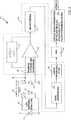
In einer weiteren, als Beispiel und nicht als Einschränkung dargelegten Ausführungsform enthält eine kombinierte Pulsfrequenz- und Blutsauerstoff-Überwachungsschaltung: eine rote LED und eine IR-LED; einen roten Photodetektor und einen IR-Photodetektor; eine Filterungs- und Verstärkungsstufe, die mit dem roten Photodetektor und dem IR-Photodetektor gekoppelt ist; einen Steuerschaltkreis, der Rückkopplung von der Filterungs- und Verstärkungsstufe empfängt und die Ströme zur roten LED und zur IR-LED steuert; und einen Analog-Digital-Umsetzer (ADU) mit einem analogen Eingang, der mit einem Ausgang der Filterungs- und Verstärkungsstufe gekoppelt ist, und einem digitalen Ausgang.In another embodiment, by way of example and not limitation, a combined pulse rate and blood oxygen monitoring circuit includes: a red LED and an IR LED; a red photodetector and an IR photodetector; a filtering and amplifying stage coupled to the red photodetector and the IR photodetector; a control circuit receiving feedback from the filtering and amplifying stage and controlling the currents to the red LED and the IR LED; and an analog-to-digital converter (ADC) having an analog input coupled to an output of the filtering and amplifying stage, and a digital output.
Diese und andere Beispiele von Kombinationen von hier unterstützten Elementen und Vorgängen sowie Vorteile davon werden Fachleuten beim Lesen der folgenden Beschreibungen und Studium der verschiedenen Figuren der Zeichnung offenbar.These and other examples of combinations of elements and operations supported herein, as well as advantages thereof, will become apparent to those skilled in the art upon reading the following descriptions and studying the various figures of the drawing.
Kurze Beschreibung der ZeichnungenBrief description of the drawings
Verschiedene Beispiele sind nun mit Bezug auf die Zeichnungen beschrieben, wobei bei gleichen Elementen und/oder Vorgängen gleiche Bezugszahlen vorgesehen sind. Die Beispiele sollen hier offenbarte Konzepte erläutern, nicht einschränken. Die Zeichnungen umfassen die folgenden Figuren:Various examples will now be described with reference to the drawings, wherein like reference numerals are provided for like elements and / or acts. The examples are intended to illustrate, not limit, concepts disclosed herein. The drawings include the following figures:
Beschreibung von AusführungsformenDescription of embodiments
Die Leuchtdiode (LED)
In einer als Beispiel und nicht als Einschränkung dargelegten Ausführungsform sind die LED
Verschiedene Teile der Pulsfrequenz-Überwachungsschaltung
Falls das gefilterte Signal stark genug ist, bestimmt ein Vorgang
Als Nächstes wird in einem Vorgang
Der Licht erzeugende Abschnitt
In bestimmten Ausführungsbeispielen werden die LEDs
Der Licht empfangende Abschnitt
Die Filter
Der Licht empfangende Abschnitt
Die rote LED
Die rote Photodiode
In diesem nicht einschränkenden Beispiel empfängt der PGA
Der ADU
Die Steuerung und Synchronisierung
Der Bus
Ebenso bestimmt, falls die IR-LED
Wenn sowohl die rote als auch die IR-Signalstärke hoch genug sind, bestimmt durch die UND-Operation
Als Nächstes wird in einem Vorgang
In diesem Beispiel sind am Gehäuse
Mit Bezug sowohl auf
Es ist daher einzusehen, dass die Schaltung
Obwohl verschiedene Beispiele unter Verwendung bestimmter Ausdrücke und Vorrichtungen beschrieben wurden, dient eine solche Beschreibung nur zur Erläuterung. Die verwendeten Worte sind Worte der Beschreibung und nicht der Einschränkung. Es versteht sich, dass Änderungen und Abwandlungen durch gewöhnliche Fachleute vorgenommen werden können, ohne vom Erfindungsgeist oder Umfang beliebiger hier beschriebener Beispiele abzuweichen. Außerdem versteht sich, dass Aspekte verschiedener anderer Beispiele entweder im Ganzen oder teilweise untereinander ausgetauscht werden können. Es ist daher beabsichtigt, dass die hier und hiernach vorgelegten Ansprüche gemäß ihrem wahren Erfindungsgeist und Umfang und ohne Einschränkung oder hemmenden Einwand ausgelegt werden.Although various examples have been described using particular terms and devices, such description is for illustration only. The words used are words of description rather than limitation. It should be understood that changes and modifications may be made by those of ordinary skill in the art without departing from the spirit or scope of any examples described herein. It is also understood that aspects of various other examples may be interchanged in whole or in part with each other. It is therefore intended that the claims here and below be interpreted in accordance with their true spirit and scope and without limitation or limitation.
Claims (14)
Translated fromGermanApplications Claiming Priority (3)
| Application Number | Priority Date | Filing Date | Title |
|---|---|---|---|
| US201261585220P | 2012-01-10 | 2012-01-10 | |
| USUS-61/585,220 | 2012-01-10 | ||
| PCT/US2013/021084WO2013106607A2 (en) | 2012-01-10 | 2013-01-10 | Heart rate and blood oxygen monitoring system |
Publications (1)
| Publication Number | Publication Date |
|---|---|
| DE112013000530T5true DE112013000530T5 (en) | 2014-10-02 |
Family
ID=48782083
Family Applications (1)
| Application Number | Title | Priority Date | Filing Date |
|---|---|---|---|
| DE112013000530.1TPendingDE112013000530T5 (en) | 2012-01-10 | 2013-01-10 | Plus frequency and blood oxygen monitoring system |
Country Status (3)
| Country | Link |
|---|---|
| US (2) | US10123711B2 (en) |
| DE (1) | DE112013000530T5 (en) |
| WO (1) | WO2013106607A2 (en) |
Families Citing this family (29)
| Publication number | Priority date | Publication date | Assignee | Title |
|---|---|---|---|---|
| US20100004518A1 (en) | 2008-07-03 | 2010-01-07 | Masimo Laboratories, Inc. | Heat sink for noninvasive medical sensor |
| US8515509B2 (en) | 2008-08-04 | 2013-08-20 | Cercacor Laboratories, Inc. | Multi-stream emitter for noninvasive measurement of blood constituents |
| EP2938259A4 (en) | 2012-12-31 | 2016-08-17 | Omni Medsci Inc | Near-infrared lasers for non-invasive monitoring of glucose, ketones, hba1c, and other blood constituents |
| US12193790B2 (en) | 2012-12-31 | 2025-01-14 | Omni Medsci, Inc. | Wearable devices comprising semiconductor diode light sources with improved signal-to-noise ratio |
| US10660526B2 (en) | 2012-12-31 | 2020-05-26 | Omni Medsci, Inc. | Near-infrared time-of-flight imaging using laser diodes with Bragg reflectors |
| US9500634B2 (en) | 2012-12-31 | 2016-11-22 | Omni Medsci, Inc. | Short-wave infrared super-continuum lasers for natural gas leak detection, exploration, and other active remote sensing applications |
| CA2895982A1 (en) | 2012-12-31 | 2014-07-03 | Omni Medsci, Inc. | Short-wave infrared super-continuum lasers for early detection of dental caries |
| WO2014143276A2 (en) | 2012-12-31 | 2014-09-18 | Omni Medsci, Inc. | Short-wave infrared super-continuum lasers for natural gas leak detection, exploration, and other active remote sensing applications |
| BR112015022658A2 (en)* | 2013-03-15 | 2017-07-18 | Theranos Inc | optical signal detection device and method |
| DE112014006082T5 (en)* | 2013-12-25 | 2016-10-27 | Asahi Kasei Kabushiki Kaisha | Pulse wave measuring device, mobile device, medical equipment system and biological information communication system |
| US10188350B2 (en) | 2014-01-07 | 2019-01-29 | Samsung Electronics Co., Ltd. | Sensor device and electronic device having the same |
| KR102132442B1 (en)* | 2014-01-07 | 2020-07-09 | 삼성전자주식회사 | Sensor device and apparatus having the same |
| US9784670B1 (en) | 2014-01-22 | 2017-10-10 | Theranos, Inc. | Unified detection system for fluorometry, luminometry and spectrometry |
| US20150257706A1 (en)* | 2014-03-17 | 2015-09-17 | Htc Corporation | Portable electronic device and method for physiological measurement |
| US10060788B2 (en) | 2014-04-07 | 2018-08-28 | Physical Enterprises Inc. | Systems and methods for monitoring physiological parameters |
| US9226663B2 (en) | 2014-04-07 | 2016-01-05 | Physical Enterprises, Inc. | Systems and methods for optical isolation in measuring physiological parameters |
| US10058254B2 (en) | 2014-04-07 | 2018-08-28 | Physical Enterprises Inc. | Systems and methods for optical sensor arrangements |
| WO2016028750A1 (en)* | 2014-08-20 | 2016-02-25 | Maxim Integrated Products, Inc. | Systems and techniques to determine whether a signal is associated with a periodic biologic function |
| JP6216303B2 (en)* | 2014-09-26 | 2017-10-18 | 京セラ株式会社 | Measuring apparatus and measuring method |
| JP6653467B2 (en)* | 2015-06-15 | 2020-02-26 | パナソニックIpマネジメント株式会社 | Pulse estimation device, pulse estimation system, and pulse estimation method |
| US10448871B2 (en) | 2015-07-02 | 2019-10-22 | Masimo Corporation | Advanced pulse oximetry sensor |
| CN106788276B (en)* | 2015-12-29 | 2020-03-13 | 深圳市汇顶科技股份有限公司 | Conversion circuit and detection circuit |
| CN106383808B (en)* | 2016-09-18 | 2019-08-02 | 时瑞科技(深圳)有限公司 | The processing system and method for heart rate electrocardiosignal |
| CN106344041A (en)* | 2016-10-27 | 2017-01-25 | 北京雷致科技有限公司 | Oximeter and blood oxygen monitoring method |
| US12106846B2 (en) | 2018-11-23 | 2024-10-01 | Arterys Inc. | Systems and methods for high bit depth rendering of medical images in a web browser |
| WO2021146333A1 (en) | 2020-01-13 | 2021-07-22 | Masimo Corporation | Wearable device with physiological parameters monitoring |
| US11723564B1 (en)* | 2021-02-01 | 2023-08-15 | Amazon Technologies, Inc. | Optical sensor light filtering in a wearable device |
| EP4370022A1 (en) | 2021-07-13 | 2024-05-22 | Masimo Corporation | Wearable device with physiological parameters monitoring |
| TWI807753B (en)* | 2022-04-01 | 2023-07-01 | 矽響先創科技股份有限公司 | Wearable heart sound detection system and method thereof |
Family Cites Families (36)
| Publication number | Priority date | Publication date | Assignee | Title |
|---|---|---|---|---|
| US4258719A (en)* | 1978-12-04 | 1981-03-31 | Hughes Aircraft Company | Heart rate measurement system |
| US4700708A (en)* | 1982-09-02 | 1987-10-20 | Nellcor Incorporated | Calibrated optical oximeter probe |
| US4880304A (en)* | 1987-04-01 | 1989-11-14 | Nippon Colin Co., Ltd. | Optical sensor for pulse oximeter |
| US4859057A (en)* | 1987-10-13 | 1989-08-22 | Lawrence Medical Systems, Inc. | Oximeter apparatus |
| US5203329A (en)* | 1989-10-05 | 1993-04-20 | Colin Electronics Co., Ltd. | Noninvasive reflectance oximeter sensor providing controlled minimum optical detection depth |
| US5638818A (en)* | 1991-03-21 | 1997-06-17 | Masimo Corporation | Low noise optical probe |
| US5246003A (en)* | 1991-08-28 | 1993-09-21 | Nellcor Incorporated | Disposable pulse oximeter sensor |
| US6172743B1 (en)* | 1992-10-07 | 2001-01-09 | Chemtrix, Inc. | Technique for measuring a blood analyte by non-invasive spectrometry in living tissue |
| US5339810A (en)* | 1993-05-03 | 1994-08-23 | Marquette Electronics, Inc. | Pulse oximetry sensor |
| US5490523A (en)* | 1994-06-29 | 1996-02-13 | Nonin Medical Inc. | Finger clip pulse oximeter |
| US5853364A (en)* | 1995-08-07 | 1998-12-29 | Nellcor Puritan Bennett, Inc. | Method and apparatus for estimating physiological parameters using model-based adaptive filtering |
| US5807767A (en)* | 1996-01-02 | 1998-09-15 | Micron Technology, Inc. | Technique for attaching die to leads |
| EP1405593B1 (en)* | 1997-09-05 | 2011-08-10 | Seiko Epson Corporation | Optical diagnostic measurement device |
| US6402690B1 (en)* | 1999-04-23 | 2002-06-11 | Massachusetts Institute Of Technology | Isolating ring sensor design |
| US6526300B1 (en)* | 1999-06-18 | 2003-02-25 | Masimo Corporation | Pulse oximeter probe-off detection system |
| US6600940B1 (en)* | 2000-08-31 | 2003-07-29 | Mallinckrodt Inc. | Oximeter sensor with digital memory |
| US6594512B2 (en)* | 2000-11-21 | 2003-07-15 | Siemens Medical Solutions Usa, Inc. | Method and apparatus for estimating a physiological parameter from a physiological signal |
| US7029628B2 (en)* | 2000-12-28 | 2006-04-18 | Stat-Chem Inc. | Portable co-oximeter |
| US6654621B2 (en)* | 2001-08-29 | 2003-11-25 | Bci, Inc. | Finger oximeter with finger grip suspension system |
| US6805673B2 (en)* | 2002-02-22 | 2004-10-19 | Datex-Ohmeda, Inc. | Monitoring mayer wave effects based on a photoplethysmographic signal |
| JP2006237737A (en)* | 2005-02-22 | 2006-09-07 | Sanyo Electric Co Ltd | Color filter array and solid-state imaging device |
| US20070073119A1 (en)* | 2005-09-29 | 2007-03-29 | James Wobermin | Wireless network connected pulse oximeter |
| US7486977B2 (en)* | 2005-10-27 | 2009-02-03 | Smiths Medical Pm, Inc. | Single use pulse oximeter |
| US8359079B2 (en)* | 2006-09-21 | 2013-01-22 | Starr Life Sciences Corporation | Pulse oximetry system and techniques for deriving cardiac and breathing parameters from extra-thoracic blood flow measurements |
| US20080076991A1 (en)* | 2006-09-21 | 2008-03-27 | Starr Life Sciences Corp. | Medical display devices for cardiac and breathing parameters derived from extra-thoracic blood flow measurements |
| US9060700B2 (en)* | 2007-09-07 | 2015-06-23 | Ingo Flore | Medical measurement device for bioelectrical impedance measurement |
| US8452366B2 (en)* | 2009-03-16 | 2013-05-28 | Covidien Lp | Medical monitoring device with flexible circuitry |
| US20100240972A1 (en)* | 2009-03-20 | 2010-09-23 | Nellcor Puritan Bennett Llc | Slider Spot Check Pulse Oximeter |
| US20100249550A1 (en)* | 2009-03-25 | 2010-09-30 | Neilcor Puritan Bennett LLC | Method And Apparatus For Optical Filtering Of A Broadband Emitter In A Medical Sensor |
| US8320985B2 (en)* | 2009-04-02 | 2012-11-27 | Empire Technology Development Llc | Touch screen interfaces with pulse oximetry |
| WO2010144670A1 (en)* | 2009-06-10 | 2010-12-16 | Medtronic, Inc. | Device and method for monitoring of absolute oxygen saturation and tissue hemoglobin concentration |
| US8311601B2 (en)* | 2009-06-30 | 2012-11-13 | Nellcor Puritan Bennett Llc | Reflectance and/or transmissive pulse oximeter |
| US9024865B2 (en)* | 2009-07-23 | 2015-05-05 | Qualcomm Incorporated | Method and apparatus for controlling mobile and consumer electronic devices |
| US8788001B2 (en)* | 2009-09-21 | 2014-07-22 | Covidien Lp | Time-division multiplexing in a multi-wavelength photon density wave system |
| US8761853B2 (en)* | 2011-01-20 | 2014-06-24 | Nitto Denko Corporation | Devices and methods for non-invasive optical physiological measurements |
| US9037204B2 (en)* | 2011-09-07 | 2015-05-19 | Covidien Lp | Filtered detector array for optical patient sensors |
- 2013
- 2013-01-10DEDE112013000530.1Tpatent/DE112013000530T5/enactivePending
- 2013-01-10USUS14/371,174patent/US10123711B2/enactiveActive
- 2013-01-10WOPCT/US2013/021084patent/WO2013106607A2/enactiveSearch and Examination
- 2018
- 2018-11-08USUS16/184,927patent/US11141075B2/enactiveActive
Also Published As
| Publication number | Publication date |
|---|---|
| US20190175036A1 (en) | 2019-06-13 |
| WO2013106607A4 (en) | 2013-10-10 |
| US20150011851A1 (en) | 2015-01-08 |
| WO2013106607A2 (en) | 2013-07-18 |
| US10123711B2 (en) | 2018-11-13 |
| WO2013106607A3 (en) | 2013-09-12 |
| US11141075B2 (en) | 2021-10-12 |
Similar Documents
| Publication | Publication Date | Title |
|---|---|---|
| DE112013000530T5 (en) | Plus frequency and blood oxygen monitoring system | |
| EP3013217B1 (en) | Device and method for determining a concentration in a sample | |
| DE102014105398A1 (en) | Circuit architecture for photodiodes | |
| DE112013004467B4 (en) | pulse measuring device, pulse measuring method and pulse measuring program | |
| DE102015216341B4 (en) | PORTABLE BIOMETRIC DEVICE AND METHOD FOR PERFORMING BIOMETRIC MEASUREMENTS | |
| CN109564485A (en) | Touch sensor panel with multi-power domain chip configuration | |
| DE102014117879A1 (en) | A pulse oximetry device and method of operating a pulse oximetry device | |
| DE102013114147A1 (en) | A touch input system and method of detecting a touch using the same | |
| DE112009002394T5 (en) | Capacitive matrix touch sensor | |
| DE102012215531A1 (en) | Capacitive touch sensor with low power consumption | |
| DE102013105525A1 (en) | Gesture detection and recognition | |
| CN105902275A (en) | Information acquisition apparatus | |
| EP3483617B1 (en) | Latency measurement method | |
| Lajnef et al. | Meet spinky: an open-source spindle and K-complex detection toolbox validated on the open-access montreal archive of sleep studies (MASS) | |
| DE102014019688A1 (en) | Electronic device | |
| DE112013004453T5 (en) | Pulse measuring device, pulse measurement method and pulse measurement program | |
| DE112015003781T5 (en) | Fingerprint sensor with synchronization signal input | |
| DE102021203156A1 (en) | SKIN-TO-SKIN CONTACT DETECTION | |
| DE102016204626A1 (en) | An array substrate and method of forming the same; Method of detecting a touch control operation of a touch-control display device | |
| DE102014119435A1 (en) | Electronic device and data processing method | |
| CN207755276U (en) | A kind of electronic device of heart rate module and acquisition heart rate | |
| DE2814358A1 (en) | CONVERTER FOR LIGHT SIGNALS INTO ELECTRIC DIGITAL SIGNALS | |
| DE112015007214T5 (en) | Demodulating a signal from an intermittently illuminated region | |
| Ignatova et al. | Effects of phase correlations in naturalistic stimuli on quantitative information coding by fly photoreceptors | |
| Burkhardt et al. | Contrast rectification and distributed encoding byon-off amacrine cells in the retina |
Legal Events
| Date | Code | Title | Description |
|---|---|---|---|
| R012 | Request for examination validly filed | ||
| R016 | Response to examination communication |