DE112009001503T5 - Capacitive touchpad and toy containing it - Google Patents
Capacitive touchpad and toy containing itDownload PDFInfo
- Publication number
- DE112009001503T5 DE112009001503T5DE112009001503TDE112009001503TDE112009001503T5DE 112009001503 T5DE112009001503 T5DE 112009001503T5DE 112009001503 TDE112009001503 TDE 112009001503TDE 112009001503 TDE112009001503 TDE 112009001503TDE 112009001503 T5DE112009001503 T5DE 112009001503T5
- Authority
- DE
- Germany
- Prior art keywords
- capacitive touch
- capacitive
- touch surface
- voltage
- touchpad
- Prior art date
- Legal status (The legal status is an assumption and is not a legal conclusion. Google has not performed a legal analysis and makes no representation as to the accuracy of the status listed.)
- Withdrawn
Links
Images


Classifications
- A—HUMAN NECESSITIES
- A63—SPORTS; GAMES; AMUSEMENTS
- A63F—CARD, BOARD, OR ROULETTE GAMES; INDOOR GAMES USING SMALL MOVING PLAYING BODIES; VIDEO GAMES; GAMES NOT OTHERWISE PROVIDED FOR
- A63F3/00—Board games; Raffle games
- A63F3/00643—Electric board games; Electric features of board games
- G—PHYSICS
- G06—COMPUTING OR CALCULATING; COUNTING
- G06F—ELECTRIC DIGITAL DATA PROCESSING
- G06F3/00—Input arrangements for transferring data to be processed into a form capable of being handled by the computer; Output arrangements for transferring data from processing unit to output unit, e.g. interface arrangements
- G06F3/01—Input arrangements or combined input and output arrangements for interaction between user and computer
- G06F3/03—Arrangements for converting the position or the displacement of a member into a coded form
- G06F3/041—Digitisers, e.g. for touch screens or touch pads, characterised by the transducing means
- G06F3/044—Digitisers, e.g. for touch screens or touch pads, characterised by the transducing means by capacitive means
- A—HUMAN NECESSITIES
- A63—SPORTS; GAMES; AMUSEMENTS
- A63F—CARD, BOARD, OR ROULETTE GAMES; INDOOR GAMES USING SMALL MOVING PLAYING BODIES; VIDEO GAMES; GAMES NOT OTHERWISE PROVIDED FOR
- A63F9/00—Games not otherwise provided for
- A63F9/24—Electric games; Games using electronic circuits not otherwise provided for
- A63F2009/2401—Detail of input, input devices
- A63F2009/2402—Input by manual operation
- A63F2009/2408—Touch-sensitive buttons
- A—HUMAN NECESSITIES
- A63—SPORTS; GAMES; AMUSEMENTS
- A63F—CARD, BOARD, OR ROULETTE GAMES; INDOOR GAMES USING SMALL MOVING PLAYING BODIES; VIDEO GAMES; GAMES NOT OTHERWISE PROVIDED FOR
- A63F9/00—Games not otherwise provided for
- A63F9/24—Electric games; Games using electronic circuits not otherwise provided for
- A63F2009/2448—Output devices
- A63F2009/245—Output devices visual
- A—HUMAN NECESSITIES
- A63—SPORTS; GAMES; AMUSEMENTS
- A63F—CARD, BOARD, OR ROULETTE GAMES; INDOOR GAMES USING SMALL MOVING PLAYING BODIES; VIDEO GAMES; GAMES NOT OTHERWISE PROVIDED FOR
- A63F9/00—Games not otherwise provided for
- A63F9/24—Electric games; Games using electronic circuits not otherwise provided for
- A63F2009/2483—Other characteristics
- A63F2009/2485—Other characteristics using a general-purpose personal computer
- A63F2009/2486—Other characteristics using a general-purpose personal computer the computer being an accessory to a board game
- A—HUMAN NECESSITIES
- A63—SPORTS; GAMES; AMUSEMENTS
- A63F—CARD, BOARD, OR ROULETTE GAMES; INDOOR GAMES USING SMALL MOVING PLAYING BODIES; VIDEO GAMES; GAMES NOT OTHERWISE PROVIDED FOR
- A63F2300/00—Features of games using an electronically generated display having two or more dimensions, e.g. on a television screen, showing representations related to the game
- A63F2300/10—Features of games using an electronically generated display having two or more dimensions, e.g. on a television screen, showing representations related to the game characterized by input arrangements for converting player-generated signals into game device control signals
- A63F2300/1068—Features of games using an electronically generated display having two or more dimensions, e.g. on a television screen, showing representations related to the game characterized by input arrangements for converting player-generated signals into game device control signals being specially adapted to detect the point of contact of the player on a surface, e.g. floor mat, touch pad
Landscapes
- Engineering & Computer Science (AREA)
- General Engineering & Computer Science (AREA)
- Theoretical Computer Science (AREA)
- Multimedia (AREA)
- Human Computer Interaction (AREA)
- Physics & Mathematics (AREA)
- General Physics & Mathematics (AREA)
- Toys (AREA)
Abstract
Translated fromGerman
Description
Translated fromGermanQuerverweis auf diesbezügliche AnmeldungenCross-reference to related applications
Die vorliegende Erfindung beansprucht die Priorität gemäß U. S. C. § 119(e) der vorläufigen US-Patentanmeldung (Provisional Patent Application) mit der Nummer 61/074,554, die am 20. Juni 2008 eingereicht wurde, und der vorläufigen US-Patentanmeldung mit der Nummer 61/083,395, die am 24. Juli 2008 eingereicht wurde, und die beide den Titel „TOY WITH CAPACITIVE TOUCHPAD AND INTEGRAL CARD READER” tragen, wobei deren Offenbarungen hierin durch Bezugnahme vollumfänglich aufgenommen sind.The present application claims priority under USC § 119 (e) of US Provisional Patent Application No. 61 / 074,554, filed June 20, 2008, and US Provisional Application No. 61 / 083,395, filed July 24, 2008, both entitled "TOY WITH CAPACITIVE TOUCHPAD AND INTEGRAL CARD READER", the disclosures of which are fully incorporated herein by reference.
Gebiet der OffenbarungArea of the revelation
Die vorliegende Offenbarung betrifft kapazitive Tastfeld-Anordnungen sowie Computerperipherieeinrichtungen, die Spielzeugen ähneln und Komponenten wie z. B. kapazitive Eingabetastfeld-Anordnungen und integrierte Kartenleser besitzen. Die Tastfelder können kapazitive Sensoren verwenden, und eine haptische Rückmeldung kann durch eine piezoelektronische Einrichtung vorgesehen sein. Bei einigen Ausführungsformen kann eine eingeschränkte Gestenerkennung zur Anwendung kommen, um den Spielwert zu erhöhen.The present disclosure relates to capacitive touchpad arrays and computer peripheral devices that are similar to toys and include components such as, for example; B. capacitive input pad assemblies and integrated card reader possess. The touch panels may use capacitive sensors, and haptic feedback may be provided by a piezo-electronic device. In some embodiments, limited gesture recognition may be used to increase the play value.
Beispiele für kapazitive Sensoren sind in den US-Patenten mit den Nummern
ZusammenfassungSummary
Es werden kapazitive Tastfeld-Anordnungen, Spielzeuge mit kapazitiven Tastfeld-Anordnungen und, in einigen Fällen, mit integrierten Kartenlesern, sowie Verfahren zum Detektieren des Kontaktierens einer kapazitiven Tastfläche vorgeschlagen. Die Kapazität einer kapazitiven Tastfläche kann sich abhängig davon, ob ein Objekt, wie z. B. ein menschlicher Finger, die Fläche kontaktiert, verändern. Eine Spannung der kapazitiven Tastfläche kann sich während eines jeden einer vorbestimmten Anzahl von periodisch wiederkehrenden Intervallen ändern. Die Kapazität der kapazitiven Tastfläche bestimmt die Zeitdauer, die erforderlich ist, um deren Spannung innerhalb eines jeden Intervalls bis zu einer Schwellenspannung zu ändern. Die Summe der Zeitdauer, welche die Spannung der kapazitiven Tastfläche benötigt, um die Schwellenspannung in einer vorgegebenen Anzahl von Intervallen zu erreichen, kann verwendet werden, um festzustellen, ob die kapazitive Tastfläche während der vorgegebenen Anzahl von Intervallen berührt wird.Capacitive touchpad arrangements, toys with capacitive touchpad arrays, and, in some cases, integrated card readers, as well as methods of detecting the contacting of a capacitive touchpad are proposed. The capacitance of a capacitive touch surface may vary depending on whether an object such. For example, a human finger contacting surface may change. A voltage of the capacitive touch area may change during each of a predetermined number of periodically recurring intervals. The capacity of the capacitive touch surface determines the amount of time required to change its voltage within each interval up to a threshold voltage. The sum of the time required for the voltage of the capacitive touch surface to reach the threshold voltage at a predetermined number of intervals may be used to determine if the capacitive touch surface is being touched during the predetermined number of intervals.
Kurzbeschreibung der ZeichnungenBrief description of the drawings
Genaue BeschreibungPrecise description
In Bezug auf die beigefügten Zeichnungen, in denen gleiche Bezugszeichen gleiche Elemente bezeichnen, ist in
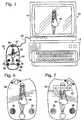
Wie in
Wie in
Bei einigen Ausführungsformen kann die Identifikationsinformation über die Spielkarte
Wenngleich viele Verfahren zum Lesen von Daten von der Spielkarte
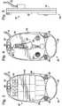
Die
Wie in den
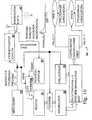
Wieder Bezug nehmend auf
Die Spielkarte
Die Karte
Durch die Verbindung mit dem Masseanschluss
Ein Spitzenpegel-Detektor
Der Zeitnehmer
Wenn ein Abtastvorgang vorüber ist, kann der in dem Akkumulator
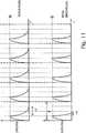
Beispielhafte Ergebnisse der in
Ein Beispiel, bei dem die kapazitive Tastfläche
Weiter mit der Logikschaltung in
An dem Ende eines jeden Intervalls T und/oder dem Beginn des nächsten Intervalls T + 1 kann die Aufladung der kapazitiven Tastfläche
Ein alternativer Logikschaltkreis ist in
Zu Beginn eines jeden Intervalls T und unmittelbar bevor die kapazitive Tastfläche
In
Beispielhafte Ergebnisse der in
Unter der Annahme einer Abtastgröße von 5 Intervallen T kann die Zeitdauer, die in dem Akkumulator
Bei einigen Ausführungsformen kann ein Signal, das von dem peripheren Spielzeug
Wenngleich Ausführungsformen eines Spielzeugs und die dazugehörigen Computersysteme und Verfahren für die Verwendung genau gezeigt und beschrieben wurden, können dennoch viele Änderungen darin vorgenommen werden. Die vorliegende Offenbarung kann ein oder mehrere unabhängige oder voneinander abhängige Ausführungen umfassen, die auf verschiedene Merkmalskombinationen, Funktionen, Elemente und/oder Eigenschaften gerichtet sind. Andere Kombinationen und Unterkombinationen von Merkmalen, Funktionen, Elementen und/oder Eigenschaften können nachträglich in dieser oder einer in Beziehung stehenden Anmeldung beansprucht werden. Derartige Änderungen, ob sie nun auf verschiedene Kombinationen gerichtet sind oder auf dieselben Kombinationen gerichtet sind, ob sie nun einen anderen, breiteren, engeren, oder gleichen Umfang haben, gelten ebenfalls als im Hauptgegenstand der vorliegenden Offenbarung enthalten. Dementsprechend sind die vorstehenden Ausführungsformen als veranschaulichend zu betrachten, wobei kein einziges Merkmal oder Element, oder eine Kombination davon, für sämtliche mögliche Kombinationen, die in der vorliegenden oder einer späteren Anmeldung beansprucht werden können, wesentlich ist. Wenn in der Beschreibung „ein” oder „ein erstes” Element oder ein Äquivalent davon wiedergegeben wird, dann umfasst die Beschreibung ein oder mehrerer solcher Elemente, so dass zwei oder mehrere solcher Elemente weder zwingend noch ausgeschlossen sind. Des Weiteren werden Ordnungsangaben, wie z. B. erste, zweite, oder dritte, für bezeichnete Elemente verwendet, um eine Unterscheidung zwischen den Elementen zu treffen, und nicht um eine bestimmte Position oder Reihenfolge solcher Elemente anzugeben, sofern nicht anderweitig speziell angegeben.While embodiments of a toy and associated computer systems and methods of use have been shown and described in detail, many changes may be made therein. The present disclosure may include one or more independent or interdependent embodiments that are directed to various combinations of features, functions, elements, and / or properties. Other combinations and subcombinations of features, functions, elements and / or properties may be claimed subsequently in this or a related application. Such changes, whether directed to various combinations or directed to the same combinations, whether of a different, wider, narrower or equal scope, are also believed to be included in the principal subject matter of the present disclosure. Accordingly, the foregoing embodiments are to be considered as illustrative, with no single feature or element, or combination thereof, being essential to all possible combinations that may be claimed in this or a later application. When "one" or "a first" element or an equivalent thereof is represented in the specification, the description includes one or more of such elements so that two or more of such elements are neither mandatory nor excluded. Furthermore, ordinal information such. B. first, second, or third, used for designated elements to make a distinction between the elements, and not to indicate a particular position or order of such elements, unless otherwise specified.
ZusammenfassungSummary
Es werden kapazitive Tastfeld-Anordnungen (
ZITATE ENTHALTEN IN DER BESCHREIBUNG QUOTES INCLUDE IN THE DESCRIPTION
Diese Liste der vom Anmelder aufgeführten Dokumente wurde automatisiert erzeugt und ist ausschließlich zur besseren Information des Lesers aufgenommen. Die Liste ist nicht Bestandteil der deutschen Patent- bzw. Gebrauchsmusteranmeldung. Das DPMA übernimmt keinerlei Haftung für etwaige Fehler oder Auslassungen.This list of the documents listed by the applicant has been generated automatically and is included solely for the better information of the reader. The list is not part of the German patent or utility model application. The DPMA assumes no liability for any errors or omissions.
Zitierte PatentliteraturCited patent literature
- US 4039940[0003]US 4039940[0003]
- US 4272916[0003]US 4272916[0003]
- US 4355300[0003]US 4355300[0003]
- US 4595913[0003]US 4595913[0003]
- US 5413518[0003]US 5413518[0003]
- US 5650597[0003]US 5650597[0003]
- US 6661239[0003]US 6661239[0003]
- US 6834251[0003]US 6834251[0003]
- US 6940291[0003]US 6940291[0003]
- US 20040219501[0003]US 20040219501[0003]
- US 4334280[0003]US 4334280[0003]
- US 6429846[0003]US 6429846[0003]
- US 6466036[0003]US 6466036[0003]
- US 20060205502[0003]US 20060205502[0003]
- US 20060089197[0003]US 20060089197[0003]
- US 20060252494[0003]US 20060252494[0003]
- US 4884974[0003]US 4884974[0003]
- US 5334022[0003]US 5334022[0003]
- US 7224934[0003]US 7224934[0003]
- US 7387560[0003]US 7387560[0003]
- US 4687200[0021]US 4687200[0021]
Claims (20)
Translated fromGermanApplications Claiming Priority (5)
| Application Number | Priority Date | Filing Date | Title |
|---|---|---|---|
| US7455408P | 2008-06-20 | 2008-06-20 | |
| US61/074,554 | 2008-06-20 | ||
| US8339508P | 2008-07-24 | 2008-07-24 | |
| US61/083,395 | 2008-07-24 | ||
| PCT/US2009/043620WO2009154900A1 (en) | 2008-06-20 | 2009-05-12 | Capacitive touchpad and toy incorporating the same |
Publications (1)
| Publication Number | Publication Date |
|---|---|
| DE112009001503T5true DE112009001503T5 (en) | 2011-04-28 |
Family
ID=41431811
Family Applications (1)
| Application Number | Title | Priority Date | Filing Date |
|---|---|---|---|
| DE112009001503TWithdrawnDE112009001503T5 (en) | 2008-06-20 | 2009-05-12 | Capacitive touchpad and toy containing it |
Country Status (5)
| Country | Link |
|---|---|
| US (2) | US8098240B2 (en) |
| CN (1) | CN102124429B (en) |
| CA (1) | CA2728410C (en) |
| DE (1) | DE112009001503T5 (en) |
| WO (1) | WO2009154900A1 (en) |
Families Citing this family (33)
| Publication number | Priority date | Publication date | Assignee | Title |
|---|---|---|---|---|
| US9354890B1 (en) | 2007-10-23 | 2016-05-31 | Marvell International Ltd. | Call stack structure for enabling execution of code outside of a subroutine and between call stack frames |
| US9442758B1 (en) | 2008-01-21 | 2016-09-13 | Marvell International Ltd. | Dynamic processor core switching |
| DE112009001503T5 (en)* | 2008-06-20 | 2011-04-28 | Mattel, Inc., El Segundo | Capacitive touchpad and toy containing it |
| US20090318234A1 (en)* | 2008-06-23 | 2009-12-24 | Ganz | Method of conducting a trade of virtual items in a virtual world |
| KR100968255B1 (en)* | 2008-07-01 | 2010-07-06 | 이병진 | Contact card recognition system and recognition method using touch screen |
| US20100100447A1 (en)* | 2008-10-21 | 2010-04-22 | Ganz | Toy system and extravaganza planner |
| US8510800B2 (en) | 2008-10-27 | 2013-08-13 | Ganz | Temporary user account for a virtual world website |
| US20100161443A1 (en)* | 2008-12-23 | 2010-06-24 | Ganz, An Ontario Partnership Consisting Of 2121200 Ontario Inc. And 2121812 Ontario Inc. | Purchases using unique codes |
| US8255807B2 (en) | 2008-12-23 | 2012-08-28 | Ganz | Item customization and website customization |
| US20110281652A1 (en)* | 2009-02-02 | 2011-11-17 | Marc Laverdiere | Touch Music Player |
| US20100325182A1 (en)* | 2009-06-17 | 2010-12-23 | Ganz, An Ontario Partnership Consisting Of 2121200 Ontario Inc., And 2121812 Ontario Inc. | Downloadable multimedia with access codes |
| US8795072B2 (en)* | 2009-10-13 | 2014-08-05 | Ganz | Method and system for providing a virtual presentation including a virtual companion and virtual photography |
| US9582443B1 (en) | 2010-02-12 | 2017-02-28 | Marvell International Ltd. | Serial control channel processor for executing time-based instructions |
| US20110199328A1 (en)* | 2010-02-18 | 2011-08-18 | Flextronics Ap, Llc | Touch screen system with acoustic and capacitive sensing |
| CN102906676A (en) | 2010-03-22 | 2013-01-30 | 美泰有限公司 | Input and output of electronic devices and data |
| US8790183B2 (en) | 2011-02-15 | 2014-07-29 | Ganz | Arcade in a virtual world with reward |
| US8884920B1 (en)* | 2011-05-25 | 2014-11-11 | Marvell International Ltd. | Programmatic sensing of capacitive sensors |
| US9069553B2 (en) | 2011-09-06 | 2015-06-30 | Marvell World Trade Ltd. | Switching tasks between heterogeneous cores |
| TWM432105U (en)* | 2011-09-19 | 2012-06-21 | Dagi Corp Ltd | Capacitive touch panel sensing card |
| US20140243102A1 (en)* | 2013-02-28 | 2014-08-28 | R2Z Innovations, Inc. | System and methods for tele-interactive play items |
| EP2873968B1 (en)* | 2013-11-14 | 2016-08-10 | Nxp B.V. | Capacitive sensing system and method |
| US10795510B2 (en) | 2016-10-25 | 2020-10-06 | Microsoft Technology Licensing, Llc | Detecting input based on a capacitive pattern |
| US10386974B2 (en) | 2017-02-07 | 2019-08-20 | Microsoft Technology Licensing, Llc | Detecting input based on a sensed capacitive input profile |
| US12210707B2 (en) | 2018-01-08 | 2025-01-28 | Kids Ii Hape Joint Venture Limited | Toys with connected play |
| EP3848103B1 (en) | 2018-01-08 | 2022-12-07 | Kids II Hape Joint Venture Limited | Children's toys with capacitive touch interactivity |
| CN112437963A (en) | 2018-05-24 | 2021-03-02 | 克兹二世有限公司 | Adaptive sensory output synchronized with input rhythm to achieve soothing effect |
| US10128837B1 (en)* | 2018-06-11 | 2018-11-13 | Horizon Group USA, INC | System and method for identifying objects using capacitive sensing technology |
| USD945535S1 (en) | 2019-01-07 | 2022-03-08 | Kids Ii Hape Joint Venture Limited | Children's play table |
| USD920277S1 (en) | 2019-07-12 | 2021-05-25 | Kids2, Inc. | Audio player |
| USD954851S1 (en) | 2019-11-25 | 2022-06-14 | Kids Ii Hape Joint Venture Limited | Toy keyboard |
| USD979656S1 (en) | 2020-12-11 | 2023-02-28 | Kids Ii Hape Joint Venture Limited | Toy drum |
| USD985676S1 (en) | 2021-01-11 | 2023-05-09 | Kids Ii Hape Joint Venture Limited | Toy drum |
| USD985677S1 (en) | 2021-01-11 | 2023-05-09 | Kids Ii Hape Joint Venture Limited | Toy guitar |
Citations (20)
| Publication number | Priority date | Publication date | Assignee | Title |
|---|---|---|---|---|
| US4039940A (en) | 1976-07-30 | 1977-08-02 | General Electric Company | Capacitance sensor |
| US4272916A (en) | 1979-12-06 | 1981-06-16 | Cpg Products Corp. | Proximity responsive toy |
| US4334280A (en) | 1980-06-09 | 1982-06-08 | Texas Instruments Incorporated | System and method for providing an audible sound and a tactile feedback in an electronic data processing system |
| US4355300A (en) | 1980-02-14 | 1982-10-19 | Coulter Systems Corporation | Indicia recognition apparatus |
| US4595913A (en) | 1983-02-10 | 1986-06-17 | Pie Associates | Capacitor touch activated switching system |
| US4687200A (en) | 1983-08-05 | 1987-08-18 | Nintendo Co., Ltd. | Multi-directional switch |
| US4884974A (en) | 1987-12-21 | 1989-12-05 | View-Master Ideal Group, Inc. | Interactive talking book and audio player assembly |
| US5334022A (en) | 1991-08-30 | 1994-08-02 | Sony Corporation | Auditory playing device |
| US5413518A (en) | 1994-01-18 | 1995-05-09 | Lin; Ming-Tuan | Proximity responsive toy |
| US5650597A (en) | 1995-01-20 | 1997-07-22 | Dynapro Systems, Inc. | Capacitive touch sensor |
| US6429846B2 (en) | 1998-06-23 | 2002-08-06 | Immersion Corporation | Haptic feedback for touchpads and other touch controls |
| US6466036B1 (en) | 1998-11-25 | 2002-10-15 | Harald Philipp | Charge transfer capacitance measurement circuit |
| US6661239B1 (en) | 2001-01-02 | 2003-12-09 | Irobot Corporation | Capacitive sensor systems and methods with increased resolution and automatic calibration |
| US20040219501A1 (en) | 2001-05-11 | 2004-11-04 | Shoot The Moon Products Ii, Llc Et Al. | Interactive book reading system using RF scanning circuit |
| US6834251B1 (en) | 2001-12-06 | 2004-12-21 | Richard Fletcher | Methods and devices for identifying, sensing and tracking objects over a surface |
| US20060089197A1 (en) | 2004-10-27 | 2006-04-27 | Nintendo Co., Ltd., | Game apparatus and storage medium storing game program |
| US20060205502A1 (en) | 2005-03-10 | 2006-09-14 | Nintendo Co., Ltd. | Storage medium storing game program and game apparatus |
| US20060252494A1 (en) | 2005-01-14 | 2006-11-09 | Ignacio Gerson | Slot machine bonus game |
| US7224934B2 (en) | 2002-03-05 | 2007-05-29 | Jeffrey D Mullen | Talking book employing photoelectronics for autonomous page recognition |
| US7387560B2 (en) | 2004-08-04 | 2008-06-17 | Mattel, Inc. | Electronic toy |
Family Cites Families (165)
| Publication number | Priority date | Publication date | Assignee | Title |
|---|---|---|---|---|
| US3232404A (en) | 1964-08-11 | 1966-02-01 | Navigation Computer Corp | Keyboard operated printer with electrical means preventing operation of plural keys |
| US3519802A (en) | 1968-11-27 | 1970-07-07 | Securadyne Ltd | Cards employing capacitor sensing of encoded data |
| US3585368A (en) | 1969-08-08 | 1971-06-15 | Thomas A Nunamaker | Apparatus for capacitively sensing information apertures in data cards |
| US3632993A (en) | 1969-08-25 | 1972-01-04 | Scanner | Color code system |
| US3777165A (en) | 1972-03-31 | 1973-12-04 | Electronics Corp America | Sensing apparatus |
| US3790756A (en) | 1972-11-08 | 1974-02-05 | Fmc Corp | Bar code reading circuitry |
| US3918028A (en) | 1973-01-05 | 1975-11-04 | Data Source Corp | Hand held optical reader |
| US4074114A (en) | 1976-03-12 | 1978-02-14 | Monarch Marking Systems, Inc. | Bar code and method and apparatus for interpreting the same |
| US4055747A (en) | 1976-05-13 | 1977-10-25 | Ebco Industries, Ltd. | Apparatus and method for the synchronous reading of data from a punched card |
| US4090092A (en) | 1976-07-16 | 1978-05-16 | General Electric Company | Shielding arrangement for a capacitive touch switch device |
| US4103252A (en) | 1976-11-26 | 1978-07-25 | Xerox Corporation | Capacitive touch-activated transducer system including a plurality of oscillators |
| US4345167A (en) | 1978-07-14 | 1982-08-17 | Calvin Noel M | Capacitance proximity sensor |
| US4359222A (en) | 1978-10-30 | 1982-11-16 | Smith Engineering | Hand-held electronic game playing device with replaceable cartridges |
| DK306081A (en) | 1981-07-10 | 1983-03-14 | Gnt Automatic As | FLOOR-BASED DIGITAL INFORMATION STORAGE AND PROCEDURES FOR READING AND CODING THE SAME |
| DK143783A (en) | 1982-06-17 | 1983-12-18 | Gnt Automatic As | DATA STORAGE |
| DE3379484D1 (en) | 1982-07-29 | 1989-04-27 | Nippon Denso Co | Apparatus for optically reading information |
| JPS5968072A (en) | 1982-10-13 | 1984-04-17 | Sharp Corp | Small electronic device for function conversion |
| US4488679A (en) | 1982-11-01 | 1984-12-18 | Western Publishing Company, Inc. | Code and reading system |
| US4550221A (en) | 1983-10-07 | 1985-10-29 | Scott Mabusth | Touch sensitive control device |
| US4599511A (en) | 1984-03-22 | 1986-07-08 | Stiller Bruno V | Card reading system |
| US4639874A (en) | 1984-04-18 | 1987-01-27 | Thermo Electron Corporation | System for monitoring and controlling position of hoists |
| JPS60263642A (en) | 1984-06-12 | 1985-12-27 | Nippon Seiko Kk | Automatic original pattern reader |
| US4743773A (en) | 1984-08-23 | 1988-05-10 | Nippon Electric Industry Co., Ltd. | Bar code scanner with diffusion filter and plural linear light source arrays |
| JPS6165760A (en) | 1984-09-07 | 1986-04-04 | Toyota Motor Corp | Production instruction device |
| US4729564A (en) | 1986-02-07 | 1988-03-08 | Marvin Glass & Associates | Card reading responsive electronic game |
| EP0272070B1 (en) | 1986-12-15 | 1995-03-01 | Omron Corporation | Input apparatus for computer |
| US4947335A (en) | 1988-09-12 | 1990-08-07 | At&T Bell Laboratories | Identification of workpiece information |
| US4952051A (en) | 1988-09-27 | 1990-08-28 | Lovell Douglas C | Method and apparatus for producing animated drawings and in-between drawings |
| US5088928A (en) | 1988-11-15 | 1992-02-18 | Chan James K | Educational/board game apparatus |
| US4969647A (en) | 1989-06-02 | 1990-11-13 | Atari Corporation | Invertible hand-held electronic game apparatus |
| US4999462A (en) | 1989-10-06 | 1991-03-12 | Summagraphics Corporation | Position determining and digitizing method and device |
| DE3933542A1 (en) | 1989-10-07 | 1991-04-18 | Kg Catts Ges Fuer Erkennungs & | CODE ARRANGEMENT AND DEVICES FOR READING AND CODING THE SAME |
| JP3085471B2 (en) | 1991-01-24 | 2000-09-11 | ソニー株式会社 | Remote commander |
| JPH0769767B2 (en) | 1991-10-16 | 1995-07-31 | インターナショナル・ビジネス・マシーンズ・コーポレイション | Touch overlay for detecting finger touch or stylus position, and detection system |
| JP3120085B2 (en) | 1991-11-21 | 2000-12-25 | 株式会社セガ | Electronic devices and information carriers |
| US5369261A (en) | 1992-02-12 | 1994-11-29 | Shamir; Harry | Multi-color information encoding system |
| US5352879A (en) | 1992-04-30 | 1994-10-04 | Eastman Kodak Company | DX bar code reader |
| DE69324067T2 (en) | 1992-06-08 | 1999-07-15 | Synaptics Inc | Object position detector |
| US7911456B2 (en) | 1992-06-08 | 2011-03-22 | Synaptics Incorporated | Object position detector with edge motion feature and gesture recognition |
| US5880411A (en) | 1992-06-08 | 1999-03-09 | Synaptics, Incorporated | Object position detector with edge motion feature and gesture recognition |
| CA2113329A1 (en) | 1993-02-02 | 1994-08-03 | Avi Arad | Talking playset |
| EP0691145A4 (en)* | 1993-02-17 | 1996-04-17 | Ace Denken Kk | Game house system utilizing storage medium |
| US5469364A (en) | 1993-03-15 | 1995-11-21 | Hughey; Bradley W. | Apparatus and methods for measuring and detecting variations in the value of a capacitor |
| JP2545571Y2 (en) | 1993-11-02 | 1997-08-25 | 株式会社トミー | Drawing toys |
| US5471040A (en) | 1993-11-15 | 1995-11-28 | May; George | Capacitive data card system |
| US5576981A (en) | 1993-11-17 | 1996-11-19 | Intermec Corporation | Portable computer with interchangeable keypad and method for operating same |
| WO1995020787A1 (en) | 1994-01-27 | 1995-08-03 | Exos, Inc. | Multimode feedback display technology |
| US5813861A (en) | 1994-02-23 | 1998-09-29 | Knowledge Kids Enterprises, Inc. | Talking phonics interactive learning device |
| US5511980A (en) | 1994-02-23 | 1996-04-30 | Leapfrog Rbt, L.L.C. | Talking phonics interactive learning device |
| GB9406702D0 (en) | 1994-04-05 | 1994-05-25 | Binstead Ronald P | Multiple input proximity detector and touchpad system |
| US5599046A (en) | 1994-06-22 | 1997-02-04 | Scientific Games Inc. | Lottery ticket structure with circuit elements |
| AU691654B2 (en) | 1994-07-28 | 1998-05-21 | Super Dimension Inc. | Computerized game board |
| US5655961A (en) | 1994-10-12 | 1997-08-12 | Acres Gaming, Inc. | Method for operating networked gaming devices |
| US6347813B1 (en) | 1994-11-09 | 2002-02-19 | Jack Star | Interactive probe system for games and books |
| GB9422911D0 (en) | 1994-11-14 | 1995-01-04 | Moonstone Technology Ltd | Capacitive touch detectors |
| US5636995A (en) | 1995-01-17 | 1997-06-10 | Stephen A. Schwartz | Interactive story book and graphics tablet apparatus and methods for operating the same |
| US6200216B1 (en) | 1995-03-06 | 2001-03-13 | Tyler Peppel | Electronic trading card |
| JP3015275B2 (en) | 1995-04-10 | 2000-03-06 | 株式会社ワコム | Position detecting device and position indicator used therein |
| US5777596A (en) | 1995-11-13 | 1998-07-07 | Symbios, Inc. | Touch sensitive flat panel display |
| US6650870B2 (en) | 1995-12-15 | 2003-11-18 | Innovision Research & Technology Plc | Data communication apparatus |
| US5730165A (en) | 1995-12-26 | 1998-03-24 | Philipp; Harald | Time domain capacitive field detector |
| US5823782A (en) | 1995-12-29 | 1998-10-20 | Tinkers & Chance | Character recognition educational system |
| US5920309A (en) | 1996-01-04 | 1999-07-06 | Logitech, Inc. | Touch sensing method and apparatus |
| US6260763B1 (en) | 1996-02-06 | 2001-07-17 | Psc Scanning, Inc. | Integral illumination source/collection lens assembly for data reading system |
| US5769643A (en) | 1996-02-07 | 1998-06-23 | Ncr Corporation | Instruction communication system |
| US5682032A (en) | 1996-02-22 | 1997-10-28 | Philipp; Harald | Capacitively coupled identity verification and escort memory apparatus |
| EP0802500B1 (en) | 1996-04-15 | 1999-08-18 | Pressenk Instruments Inc. | Padless touch sensor |
| US6102397A (en) | 1996-05-10 | 2000-08-15 | Lee; Dennis H | Computer interface apparatus for an amusement device |
| US5831597A (en) | 1996-05-24 | 1998-11-03 | Tanisys Technology, Inc. | Computer input device for use in conjunction with a mouse input device |
| US5914477A (en) | 1996-06-26 | 1999-06-22 | Ncr Corporation | Line focus barcode scanner |
| US5760383A (en) | 1996-07-29 | 1998-06-02 | Ncr Corporation | Method and apparatus for simulating bar code |
| US6362737B1 (en) | 1998-06-02 | 2002-03-26 | Rf Code, Inc. | Object Identification system with adaptive transceivers and methods of operation |
| US5949060A (en) | 1996-11-01 | 1999-09-07 | Coincard International, Inc. | High security capacitive card system |
| US6327459B2 (en) | 1997-03-14 | 2001-12-04 | Tv Interactive Data Corporation | Remote control with a detachable insert |
| WO1998040863A1 (en) | 1997-03-14 | 1998-09-17 | Tv Interactive Data Corporation | A method of detachably attaching an insert to a remote control base and the resulting remote control |
| US5933102A (en) | 1997-09-24 | 1999-08-03 | Tanisys Technology, Inc. | Capacitive sensitive switch method and system |
| US6097189A (en) | 1997-09-29 | 2000-08-01 | The United States Of America As Represented By The Administrator Of The National Aeronautics And Space Administration | Object locating system |
| US6105869A (en) | 1997-10-31 | 2000-08-22 | Microscan Systems, Incorporated | Symbol reading device including optics for uniformly illuminating symbology |
| KR100595922B1 (en) | 1998-01-26 | 2006-07-05 | 웨인 웨스터만 | Method and apparatus for integrating manual input |
| US5977867A (en) | 1998-05-29 | 1999-11-02 | Nortel Networks Corporation | Touch pad panel with tactile feedback |
| US6168494B1 (en) | 1998-08-08 | 2001-01-02 | Robert William Engel | Expandable and changeable playset building system |
| US6157454A (en) | 1998-09-02 | 2000-12-05 | Colorimeter, Llc | Miniature colorimeter |
| US7334735B1 (en) | 1998-10-02 | 2008-02-26 | Beepcard Ltd. | Card for interaction with a computer |
| GB2344257A (en) | 1998-11-26 | 2000-05-31 | Innovision Research And Techno | Data communication apparatus and board game |
| US6452514B1 (en)* | 1999-01-26 | 2002-09-17 | Harald Philipp | Capacitive sensor and array |
| FR2789907B1 (en) | 1999-02-19 | 2003-08-22 | Janick Simeray | INTELLIGENT AND SELF-ADAPTIVE ELECTRONICS FOR TOY WITH ACCESSORIES |
| US6202929B1 (en) | 1999-03-10 | 2001-03-20 | Micro-Epsilon Mess Technik | Capacitive method and apparatus for accessing information encoded by a differentially conductive pattern |
| GB2351029B (en) | 1999-06-16 | 2003-04-02 | Charles Joseph Henderson | Improvements in, or relating to, playing cards |
| US6227931B1 (en) | 1999-07-02 | 2001-05-08 | Judith Ann Shackelford | Electronic interactive play environment for toy characters |
| GB9929894D0 (en) | 1999-12-20 | 2000-02-09 | Central Research Lab Ltd | Interactive design and amusement system |
| US6822635B2 (en) | 2000-01-19 | 2004-11-23 | Immersion Corporation | Haptic interface for laptop computers and other portable devices |
| US6761637B2 (en) | 2000-02-22 | 2004-07-13 | Creative Kingdoms, Llc | Method of game play using RFID tracking device |
| US6572378B1 (en) | 2000-02-29 | 2003-06-03 | Rehco, Llc | Electronic drawing assist toy |
| US7081033B1 (en) | 2000-03-07 | 2006-07-25 | Hasbro, Inc. | Toy figure for use with multiple, different game systems |
| US6615155B2 (en) | 2000-03-09 | 2003-09-02 | Super Dimension Ltd. | Object tracking using a single sensor or a pair of sensors |
| JP3946931B2 (en) | 2000-04-25 | 2007-07-18 | 船井電機株式会社 | Tablet-type information terminal device and homepage browsing system using the same |
| US6668156B2 (en) | 2000-04-27 | 2003-12-23 | Leapfrog Enterprises, Inc. | Print media receiving unit including platform and print media |
| NO20003006L (en) | 2000-06-09 | 2001-12-10 | Idex Asa | Mouse |
| US6443796B1 (en) | 2000-06-19 | 2002-09-03 | Judith Ann Shackelford | Smart blocks |
| JP3910019B2 (en) | 2000-07-04 | 2007-04-25 | アルプス電気株式会社 | Input device |
| US6593755B1 (en) | 2000-07-31 | 2003-07-15 | Banner Engineering Corporation | Method and apparatus for detection sensor shielding |
| JP2002055763A (en) | 2000-08-11 | 2002-02-20 | Alps Electric Co Ltd | Controller |
| US6772948B2 (en) | 2000-12-28 | 2004-08-10 | Ericsson Inc. | Manual bar code scanner with improved reliability |
| FR2819907B1 (en) | 2001-01-25 | 2003-03-28 | Berchet Groupe Soc | INTERACTION DEVICE WITH A MICROCOMPUTER |
| US6580600B2 (en) | 2001-02-20 | 2003-06-17 | Nippon Soken, Inc. | Capacitance type humidity sensor and manufacturing method of the same |
| US6657616B2 (en) | 2001-03-16 | 2003-12-02 | Invensys Appliance Controls Company | Capacitive touch keyboard |
| GB0114456D0 (en) | 2001-06-14 | 2001-08-08 | Koninkl Philips Electronics Nv | Object sensing |
| US6954199B2 (en) | 2001-06-18 | 2005-10-11 | Leapfrog Enterprises, Inc. | Three dimensional interactive system |
| JP3826747B2 (en) | 2001-08-06 | 2006-09-27 | 株式会社コナミデジタルエンタテインメント | GAME DEVICE AND PROGRAM |
| US7254775B2 (en) | 2001-10-03 | 2007-08-07 | 3M Innovative Properties Company | Touch panel system and method for distinguishing multiple touch inputs |
| WO2003043709A1 (en) | 2001-11-14 | 2003-05-30 | 4Kids Entertainment Licensing, Inc. | Object recognition toys and games |
| US7265746B2 (en) | 2003-06-04 | 2007-09-04 | Illinois Tool Works Inc. | Acoustic wave touch detection circuit and method |
| US6825833B2 (en) | 2001-11-30 | 2004-11-30 | 3M Innovative Properties Company | System and method for locating a touch on a capacitive touch screen |
| TWI235926B (en) | 2002-01-11 | 2005-07-11 | Sonix Technology Co Ltd | A method for producing indicators and processing system, coordinate positioning system and electronic book system utilizing the indicators |
| CA2474791A1 (en) | 2002-02-06 | 2003-08-14 | Leapfrog Enterprises, Inc. | Write on interactive apparatus and method |
| CA2457022C (en) | 2002-03-20 | 2008-02-05 | Symbol Technologies, Inc. | Image capture system and method using a common imaging array |
| CN100504957C (en) | 2002-05-30 | 2009-06-24 | 麦特尔公司 | Interactive multi-sensing reading system electronic device and operation method thereof |
| US7219843B2 (en) | 2002-06-04 | 2007-05-22 | Hand Held Products, Inc. | Optical reader having a plurality of imaging modules |
| US20040002387A1 (en) | 2002-06-26 | 2004-01-01 | Grady Daniel Patrick | Card reader and scanner device and methods of using same |
| US6802452B2 (en) | 2002-07-12 | 2004-10-12 | Ali Lebaschi | Bar code scanner and method |
| US20040104890A1 (en) | 2002-09-05 | 2004-06-03 | Leapfrog Enterprises, Inc. | Compact book and apparatus using print media |
| JP2006504948A (en) | 2002-10-31 | 2006-02-09 | フィリップ、ハラルド | Capacitive position sensor using charge transfer |
| JP4452446B2 (en) | 2003-01-20 | 2010-04-21 | 新世代株式会社 | Entertainment device using card |
| JPWO2004079641A1 (en) | 2003-03-07 | 2006-06-08 | セキュアカードインターナショナル | Capacitive data storage method, various systems using the method, and various products |
| TW588327B (en) | 2003-03-19 | 2004-05-21 | Sonix Technology Co Ltd | Output control apparatus of pulse width modulator |
| EP1616288A4 (en) | 2003-04-07 | 2008-02-27 | Silverbrook Res Pty Ltd | LASER SCANNING DEVICE FOR PRINTING PRODUCT IDENTIFICATION CODES |
| AU2007254700B2 (en) | 2003-04-07 | 2010-04-01 | Silverbrook Research Pty Ltd | Communication Facilitation |
| US6937152B2 (en) | 2003-04-08 | 2005-08-30 | Shoot The Moon Products Ii, Llc | Wireless interactive doll-houses and playsets therefor |
| US20050043076A1 (en) | 2003-08-21 | 2005-02-24 | Lin Yuhjen James | RPG toys playing process and RPG toy for playing the process |
| US7294060B2 (en) | 2003-09-03 | 2007-11-13 | Mattel, Inc. | Interactive device |
| US20050208458A1 (en) | 2003-10-16 | 2005-09-22 | Leapfrog Enterprises, Inc. | Gaming apparatus including platform |
| US7145552B2 (en) | 2003-10-22 | 2006-12-05 | Solectron Corporation | Electric field proximity keyboards and detection systems |
| US7190356B2 (en) | 2004-02-12 | 2007-03-13 | Sentelic Corporation | Method and controller for identifying double tap gestures |
| WO2005088580A1 (en) | 2004-03-09 | 2005-09-22 | Mattel, Inc. | A writing system for teaching a writing objective |
| US20050266386A1 (en) | 2004-05-28 | 2005-12-01 | Leapfrog Enterprises, Inc. | Print media apparatus including stroke recognition |
| US8297979B2 (en) | 2004-06-01 | 2012-10-30 | Mattel, Inc. | Electronic learning device with a graphic user interface for interactive writing |
| US20070132733A1 (en) | 2004-06-08 | 2007-06-14 | Pranil Ram | Computer Apparatus with added functionality |
| US20060017702A1 (en) | 2004-07-23 | 2006-01-26 | Chung-Yi Shen | Touch control type character input method and control module thereof |
| JP4363281B2 (en) | 2004-09-08 | 2009-11-11 | オムロン株式会社 | Capacity measuring device and method, and program |
| WO2006038905A1 (en) | 2004-09-10 | 2006-04-13 | Karl Ruping | Method and system for interactive character gaming |
| US20070202952A1 (en) | 2004-09-27 | 2007-08-30 | Stonelore Expeditions, Llc | Trading Card Games And Methods Of Play |
| TWI302644B (en) | 2004-09-29 | 2008-11-01 | Seiko Epson Corp | Electro-optical device, image forming apparatus, and image reader |
| US7167675B2 (en) | 2004-10-15 | 2007-01-23 | Leapfrog Enterprises, Inc. | Magnetic switch and apparatus including magnetic switch |
| JP4319975B2 (en)* | 2004-12-21 | 2009-08-26 | アルプス電気株式会社 | Input device |
| US7155976B2 (en) | 2005-01-05 | 2007-01-02 | Industrial Technology Research Institute | Rotation sensing apparatus and method for manufacturing the same |
| GB2421917A (en) | 2005-01-07 | 2006-07-12 | Nicholas J Stone | Cards with circuit elements |
| US7023221B1 (en) | 2005-05-09 | 2006-04-04 | Holylite Microectronics Corporation | Structure of object proximity and position detector |
| GB2429111A (en) | 2005-08-10 | 2007-02-14 | Nicholas Jim Stone | Electronic tag |
| TW200717293A (en) | 2005-10-25 | 2007-05-01 | Elan Microelectronics Corp | Method to detect an object on a touch pad |
| JP2007122326A (en) | 2005-10-27 | 2007-05-17 | Alps Electric Co Ltd | Input device and electronic apparatus using the input device |
| JP4777121B2 (en) | 2005-11-30 | 2011-09-21 | 日本写真印刷株式会社 | Capacitive touch screen |
| EP1993689A4 (en) | 2006-02-09 | 2009-11-04 | Disney Entpr Inc | ELECTRONIC GAME WITH COVER BOARD |
| US7993201B2 (en) | 2006-02-09 | 2011-08-09 | Disney Enterprises, Inc. | Electronic game with overlay card |
| GB2436634A (en) | 2006-03-28 | 2007-10-03 | Avantone Oy | Machine readable code system |
| US8169421B2 (en) | 2006-06-19 | 2012-05-01 | Cypress Semiconductor Corporation | Apparatus and method for detecting a touch-sensor pad gesture |
| US20080023553A1 (en) | 2006-07-31 | 2008-01-31 | Robert Jones | Optical reader having integral lens and diffuser |
| DE202006013070U1 (en) | 2006-08-25 | 2006-11-30 | Printed Systems Gmbh | Playing card loading device, has code arrangement of conductive organic polymers and computer having screen for visualization of information in arrangement, where polymers are pressed on substrate layers using mass pressing process |
| JP2007095098A (en) | 2006-12-04 | 2007-04-12 | Fujitsu Ltd | Touch panel device |
| US7755615B2 (en) | 2006-12-18 | 2010-07-13 | Motorola, Inc. | Optical shuttered touchscreen and method therefor |
| US8542211B2 (en) | 2007-01-03 | 2013-09-24 | Apple Inc. | Projection scan multi-touch sensor array |
| US8125456B2 (en) | 2007-01-03 | 2012-02-28 | Apple Inc. | Multi-touch auto scanning |
| US8049732B2 (en) | 2007-01-03 | 2011-11-01 | Apple Inc. | Front-end signal compensation |
| DE112009001503T5 (en)* | 2008-06-20 | 2011-04-28 | Mattel, Inc., El Segundo | Capacitive touchpad and toy containing it |
| CN101776880B (en)* | 2009-01-13 | 2013-05-01 | 鸿富锦精密工业(深圳)有限公司 | Hand cranking wheel control system and method |
| CN101840294B (en)* | 2010-01-21 | 2012-01-18 | 宸鸿科技(厦门)有限公司 | Method for scanning projective capacitive touch panel |
- 2009
- 2009-05-12DEDE112009001503Tpatent/DE112009001503T5/ennot_activeWithdrawn
- 2009-05-12CNCN200980132242.3Apatent/CN102124429B/ennot_activeExpired - Fee Related
- 2009-05-12USUS12/464,614patent/US8098240B2/ennot_activeExpired - Fee Related
- 2009-05-12CACA2728410Apatent/CA2728410C/ennot_activeExpired - Fee Related
- 2009-05-12WOPCT/US2009/043620patent/WO2009154900A1/enactiveApplication Filing
- 2011
- 2011-12-13USUS13/324,857patent/US8400426B2/ennot_activeExpired - Fee Related
Patent Citations (21)
| Publication number | Priority date | Publication date | Assignee | Title |
|---|---|---|---|---|
| US4039940A (en) | 1976-07-30 | 1977-08-02 | General Electric Company | Capacitance sensor |
| US4272916A (en) | 1979-12-06 | 1981-06-16 | Cpg Products Corp. | Proximity responsive toy |
| US4355300A (en) | 1980-02-14 | 1982-10-19 | Coulter Systems Corporation | Indicia recognition apparatus |
| US4334280A (en) | 1980-06-09 | 1982-06-08 | Texas Instruments Incorporated | System and method for providing an audible sound and a tactile feedback in an electronic data processing system |
| US4595913A (en) | 1983-02-10 | 1986-06-17 | Pie Associates | Capacitor touch activated switching system |
| US4687200A (en) | 1983-08-05 | 1987-08-18 | Nintendo Co., Ltd. | Multi-directional switch |
| US4884974A (en) | 1987-12-21 | 1989-12-05 | View-Master Ideal Group, Inc. | Interactive talking book and audio player assembly |
| US5334022A (en) | 1991-08-30 | 1994-08-02 | Sony Corporation | Auditory playing device |
| US5413518A (en) | 1994-01-18 | 1995-05-09 | Lin; Ming-Tuan | Proximity responsive toy |
| US5650597A (en) | 1995-01-20 | 1997-07-22 | Dynapro Systems, Inc. | Capacitive touch sensor |
| US6429846B2 (en) | 1998-06-23 | 2002-08-06 | Immersion Corporation | Haptic feedback for touchpads and other touch controls |
| US6466036B1 (en) | 1998-11-25 | 2002-10-15 | Harald Philipp | Charge transfer capacitance measurement circuit |
| US6661239B1 (en) | 2001-01-02 | 2003-12-09 | Irobot Corporation | Capacitive sensor systems and methods with increased resolution and automatic calibration |
| US6940291B1 (en) | 2001-01-02 | 2005-09-06 | Irobot Corporation | Capacitive sensor systems and methods with increased resolution and automatic calibration |
| US20040219501A1 (en) | 2001-05-11 | 2004-11-04 | Shoot The Moon Products Ii, Llc Et Al. | Interactive book reading system using RF scanning circuit |
| US6834251B1 (en) | 2001-12-06 | 2004-12-21 | Richard Fletcher | Methods and devices for identifying, sensing and tracking objects over a surface |
| US7224934B2 (en) | 2002-03-05 | 2007-05-29 | Jeffrey D Mullen | Talking book employing photoelectronics for autonomous page recognition |
| US7387560B2 (en) | 2004-08-04 | 2008-06-17 | Mattel, Inc. | Electronic toy |
| US20060089197A1 (en) | 2004-10-27 | 2006-04-27 | Nintendo Co., Ltd., | Game apparatus and storage medium storing game program |
| US20060252494A1 (en) | 2005-01-14 | 2006-11-09 | Ignacio Gerson | Slot machine bonus game |
| US20060205502A1 (en) | 2005-03-10 | 2006-09-14 | Nintendo Co., Ltd. | Storage medium storing game program and game apparatus |
Also Published As
| Publication number | Publication date |
|---|---|
| WO2009154900A1 (en) | 2009-12-23 |
| US8400426B2 (en) | 2013-03-19 |
| US20120081336A1 (en) | 2012-04-05 |
| US8098240B2 (en) | 2012-01-17 |
| CN102124429A (en) | 2011-07-13 |
| CN102124429B (en) | 2015-06-24 |
| CA2728410C (en) | 2014-05-06 |
| US20090318229A1 (en) | 2009-12-24 |
| CA2728410A1 (en) | 2009-12-23 |
Similar Documents
| Publication | Publication Date | Title |
|---|---|---|
| DE112009001503T5 (en) | Capacitive touchpad and toy containing it | |
| DE102011017251B4 (en) | Use of random sampling technique to reduce finger-locked noise | |
| DE60301831T2 (en) | Capacitive keyboard with reduced ambiguity in input | |
| DE60207443T2 (en) | SENSOR DEVICE FOR AN OPTICAL INDICATOR, SUCH AS AN OPTICAL MOUSE | |
| DE102013215800A1 (en) | Active stylus with passive counter capacitance measurements | |
| DE69930774T2 (en) | Touch-sensitive panel for on-screen cursor movement control | |
| DE112009002576T5 (en) | Touch position detection method and apparatus | |
| DE102011085464A1 (en) | Capacitive touchscreen system for electronic device has gain capacitor, which accumulates charge representative of capacitances in sense electrode during first stage and transfers charge to feedback capacitor during second stage | |
| DE102011007169A1 (en) | Multichip touch screen | |
| DE102014222429A1 (en) | Pen with asymmetric electronic properties | |
| DE102013215676A1 (en) | Self-capacitance measurement for active stylus | |
| DE102012219000B4 (en) | Touch sensor device with modulated control signal for communication with active stylus | |
| DE102012215531A1 (en) | Capacitive touch sensor with low power consumption | |
| DE102013206448A1 (en) | Measuring circuit for touch sensor of e.g. laptop computer, determines occurrence of touch input on sensor, based on charge voltage level obtained by the modification of voltage across integration capacitor from reference voltage level | |
| DE112009002585T5 (en) | Sensor and detection method | |
| DE112009002587T5 (en) | Noise handling in capacitive touch sensors | |
| DE202012102057U1 (en) | Active stylus with filter | |
| DE102017208675A1 (en) | Compensation circuit for touch sensors | |
| DE102011085528A1 (en) | Capacitive touch screen system with touch or object position coding during analog-to-digital conversion | |
| DE112015005290T5 (en) | Full wave synchronous rectification for self-capacitance detection | |
| DE102012213752A1 (en) | Cancellation of a parasitic capacitance in a sensor interface | |
| DE202013012771U1 (en) | Touch sensor control sensor hub | |
| EP1717732B1 (en) | Method for manufacturing a portable data carrier | |
| DE112019003101T5 (en) | PARALLEL DETECTION AND MEASUREMENT OF CAPACITIVE SENSOR CHANNELS AND RELATED SYSTEMS, METHODS, AND DEVICES | |
| DE3611678A1 (en) | COIN DISCRIMINATION DEVICE |
Legal Events
| Date | Code | Title | Description |
|---|---|---|---|
| OP8 | Request for examination as to paragraph 44 patent law | ||
| R016 | Response to examination communication | ||
| R082 | Change of representative | Representative=s name:WEICKMANN & WEICKMANN PATENTANWAELTE - RECHTSA, DE Representative=s name:PATENTANWAELTE WEICKMANN & WEICKMANN, DE | |
| R079 | Amendment of ipc main class | Free format text:PREVIOUS MAIN CLASS: G06F0003045000 Ipc:G06F0003044000 | |
| R119 | Application deemed withdrawn, or ip right lapsed, due to non-payment of renewal fee |