DE112006000144B4 - vehicle - Google Patents
vehicleDownload PDFInfo
- Publication number
- DE112006000144B4 DE112006000144B4DE112006000144.2TDE112006000144TDE112006000144B4DE 112006000144 B4DE112006000144 B4DE 112006000144B4DE 112006000144 TDE112006000144 TDE 112006000144TDE 112006000144 B4DE112006000144 B4DE 112006000144B4
- Authority
- DE
- Germany
- Prior art keywords
- fuel gas
- vehicle
- gas tank
- tank
- hydrogen
- Prior art date
- Legal status (The legal status is an assumption and is not a legal conclusion. Google has not performed a legal analysis and makes no representation as to the accuracy of the status listed.)
- Expired - Fee Related
Links
- 239000002737fuel gasSubstances0.000claimsabstractdescription88
- 239000001257hydrogenSubstances0.000claimsabstractdescription72
- 229910052739hydrogenInorganic materials0.000claimsabstractdescription72
- 239000000446fuelSubstances0.000claimsabstractdescription39
- 238000009423ventilationMethods0.000claimsabstractdescription10
- 239000000463materialSubstances0.000claimsabstractdescription3
- 125000004435hydrogen atomChemical class[H]*0.000claims2
- UFHFLCQGNIYNRP-UHFFFAOYSA-NHydrogenChemical compound[H][H]UFHFLCQGNIYNRP-UHFFFAOYSA-N0.000abstractdescription61
- 150000002431hydrogenChemical class0.000abstractdescription9
- 238000007789sealingMethods0.000abstract1
- 239000000155meltSubstances0.000description11
- 239000007789gasSubstances0.000description4
- VNWKTOKETHGBQD-UHFFFAOYSA-NmethaneChemical compoundCVNWKTOKETHGBQD-UHFFFAOYSA-N0.000description4
- 238000000034methodMethods0.000description2
- 239000003345natural gasSubstances0.000description2
- NJPPVKZQTLUDBO-UHFFFAOYSA-NnovaluronChemical compoundC1=C(Cl)C(OC(F)(F)C(OC(F)(F)F)F)=CC=C1NC(=O)NC(=O)C1=C(F)C=CC=C1FNJPPVKZQTLUDBO-UHFFFAOYSA-N0.000description2
- 230000002159abnormal effectEffects0.000description1
- 238000004378air conditioningMethods0.000description1
- 238000010790dilutionMethods0.000description1
- 239000012895dilutionSubstances0.000description1
- 230000007257malfunctionEffects0.000description1
- 238000012986modificationMethods0.000description1
- 230000004048modificationEffects0.000description1
- 230000001105regulatory effectEffects0.000description1
- 238000000926separation methodMethods0.000description1
Images

Classifications
- B—PERFORMING OPERATIONS; TRANSPORTING
- B60—VEHICLES IN GENERAL
- B60K—ARRANGEMENT OR MOUNTING OF PROPULSION UNITS OR OF TRANSMISSIONS IN VEHICLES; ARRANGEMENT OR MOUNTING OF PLURAL DIVERSE PRIME-MOVERS IN VEHICLES; AUXILIARY DRIVES FOR VEHICLES; INSTRUMENTATION OR DASHBOARDS FOR VEHICLES; ARRANGEMENTS IN CONNECTION WITH COOLING, AIR INTAKE, GAS EXHAUST OR FUEL SUPPLY OF PROPULSION UNITS IN VEHICLES
- B60K15/00—Arrangement in connection with fuel supply of combustion engines or other fuel consuming energy converters, e.g. fuel cells; Mounting or construction of fuel tanks
- B60K15/03—Fuel tanks
- B60K15/063—Arrangement of tanks
- B60K15/067—Mounting of tanks
- B60K15/07—Mounting of tanks of gas tanks
- B—PERFORMING OPERATIONS; TRANSPORTING
- B60—VEHICLES IN GENERAL
- B60K—ARRANGEMENT OR MOUNTING OF PROPULSION UNITS OR OF TRANSMISSIONS IN VEHICLES; ARRANGEMENT OR MOUNTING OF PLURAL DIVERSE PRIME-MOVERS IN VEHICLES; AUXILIARY DRIVES FOR VEHICLES; INSTRUMENTATION OR DASHBOARDS FOR VEHICLES; ARRANGEMENTS IN CONNECTION WITH COOLING, AIR INTAKE, GAS EXHAUST OR FUEL SUPPLY OF PROPULSION UNITS IN VEHICLES
- B60K15/00—Arrangement in connection with fuel supply of combustion engines or other fuel consuming energy converters, e.g. fuel cells; Mounting or construction of fuel tanks
- B60K15/03—Fuel tanks
- B60K15/063—Arrangement of tanks
- B60K2015/0639—Arrangement of tanks the fuel tank is arranged near or in the roof
- B—PERFORMING OPERATIONS; TRANSPORTING
- B60—VEHICLES IN GENERAL
- B60Y—INDEXING SCHEME RELATING TO ASPECTS CROSS-CUTTING VEHICLE TECHNOLOGY
- B60Y2200/00—Type of vehicle
- B60Y2200/10—Road Vehicles
- B60Y2200/14—Trucks; Load vehicles, Busses
- B60Y2200/143—Busses
- B—PERFORMING OPERATIONS; TRANSPORTING
- B60—VEHICLES IN GENERAL
- B60Y—INDEXING SCHEME RELATING TO ASPECTS CROSS-CUTTING VEHICLE TECHNOLOGY
- B60Y2200/00—Type of vehicle
- B60Y2200/10—Road Vehicles
- B60Y2200/14—Trucks; Load vehicles, Busses
- B60Y2200/143—Busses
- B60Y2200/1432—Low floor busses
Landscapes
- Engineering & Computer Science (AREA)
- Life Sciences & Earth Sciences (AREA)
- Sustainable Development (AREA)
- Sustainable Energy (AREA)
- Chemical & Material Sciences (AREA)
- Combustion & Propulsion (AREA)
- Transportation (AREA)
- Mechanical Engineering (AREA)
- Cooling, Air Intake And Gas Exhaust, And Fuel Tank Arrangements In Propulsion Units (AREA)
- Body Structure For Vehicles (AREA)
- Filling Or Discharging Of Gas Storage Vessels (AREA)
- Fuel Cell (AREA)
Abstract
Translated fromGermanDescription
Translated fromGermanTechnisches GebietTechnical area
Die vorliegende Erfindung betrifft ein Fahrzeug, an das wenigstens ein Kraftstoffgastank, der Kraftstoffgas speichert, montiert ist.The present invention relates to a vehicle to which at least one fuel gas tank storing fuel gas is mounted.
Stand der TechnikState of the art
Als ein herkömmliches Fahrzeug diesen Typs, wird ein Bus vorgeschlagen, bei dem eine Mehrzahl von Kraftstoffgastanks, von denen jeder einen Ventilkörper aufweist, der an einer Auslassöffnung an einem Frontende in einer Längsrichtung montiert ist, und verdichtetes Erdgas speichert, auf einem Dach eines Fahrzeugs derart montiert ist, dass die Längsrichtung der Kraftstoffgastanks in einer Fahrzeug-Vorwärts/Rückwärts-Richtung ist (siehe beispielsweise die
Die Verwendung von gasförmigem Kraftstoff, insbesondere Wasserstoff, für den Antrieb von Fahrzeugen wird zudem in den folgenden Artikeln diskutiert:
Alwin Berti: Der neue MAN Brennstoffzellenbus.
(siehe: http://www.brennstoffzellenbus.de/bus2004/bsz04-1d.htm und http://www.brennstoffzellenbus.de/bus2004/bsz04-3d.htm)
H2Mobility: Hydrogen Vehicles.
(siehe http://www.netinform.net/h2/H2Mobility/Default.aspx)
Wurster, R. et. al.: Fuel Cell Propulsion for Urban Duty Vehicles – Bavarian Fuel Cell Bus Project. In: the 12. World Hydrogen Energy Conference, Buenos Aires, Argentina, June 1998,
(siehe: http://www.netinform.de/H2/files/pdf/Bavarian_Fuel_Cell_Bus_Project.pdf)
Schuckert, Manfred: The CUTE hydrogen fuel cell bus demonstration project – an Update. In: CUTE, June 17, 2003
(siehe: ftp://ftp.cordis.europa.eu(pub/sustdev/docs/energy/sustdev_h2_sessionb_schuckert.pdf)The use of gaseous fuel, in particular hydrogen, for driving vehicles is also discussed in the following articles:
Alwin Berti: The new MAN fuel cell bus.
(see: http://www.brennstoffzellenbus.de/bus2004/bsz04-1d.htm and http://www.brennstoffzellenbus.de/bus2004/bsz04-3d.htm)
H2Mobility: Hydrogen Vehicles.
(see http://www.netinform.net/h2/H2Mobility/Default.aspx)
Wurster, R. et. al .: Fuel Cell Propulsion for Urban Duty Vehicles - Bavarian Fuel Cell Bus Project. In: the 12th World Hydrogen Energy Conference, Buenos Aires, Argentina, June 1998,
(see: http://www.netinform.de/H2/files/pdf/Bavarian_Fuel_Cell_Bus_Project.pdf)
Schuckert, Manfred: The CUTE hydrogen fuel cell bus demonstration project - an update. In: CUTE, June 17, 2003
(see: ftp://ftp.cordis.europa.eu (pub / sustdev / docs / energy / sustdev_h2_sessionb_schuckert.pdf)
Ein Aufbau für einen Bus mit einem daran montierten Kraftstoffgastank ist ferner aus der
Offenbarung der ErfindungDisclosure of the invention
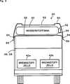
Beim vorstehend beschriebenen Fahrzeug wird jedoch eine Plattform (Podest, Standfläche, Treppenabsatz, Ein- bzw. Ausstieg) oft in einer Seitenfläche des Fahrzeugs vorgesehen, und daher ist die Öffnung des Kraftstoffgastanks bisweilen relativ nah an der Plattform angeordnet. Wenn das Kraftstoffgas außerhalb des Kraftstoffgastanks abgegeben wird, wird der Einfluss des abgegebenen Gaskraftstoffs auf der Plattform in diesem Fall bisweilen unzureichend herabgesetzt. Ein angenommener Fall, bei dem Kraftstoff nach außerhalb des Kraftstoffgastanks abgegeben wird, liegt in dem Fall vor, bei dem eine Störung des Ventilkörpers eine Leckage des Kraftstoffgases verursacht, oder in dem Fall, bei dem der Ventilkörper bei anomalem Druck im Tank geöffnet wird.In the vehicle described above, however, a platform (pedestal, footprint, landing, entry and exit) is often provided in a side surface of the vehicle, and therefore, the opening of the fuel gas tank is sometimes located relatively close to the platform. In this case, when the fuel gas is discharged outside the fuel gas tank, the influence of the discharged gas fuel on the platform is sometimes insufficiently lowered. An assumed case where fuel is discharged outside the fuel gas tank exists in the case where a malfunction of the valve body causes leakage of the fuel gas or in the case where the valve body is opened at an abnormal pressure in the tank.
Die vorliegende Erfindung hat zur Aufgabe, den Einfluss des Kraftstoffgases, das nach außerhalb eines Kraftstoffgastanks abgegeben wird, auf eine Plattform herabzusetzen. Ebenso ist es Aufgabe der vorliegenden Erfindung, das Kraftstoffgas, das nach außerhalb des Kraftstoffgastanks abgegeben wird, zu verdünnen.The object of the present invention is to reduce the influence of the fuel gas discharged outside a fuel gas tank on a platform. It is also an object of the present invention to dilute the fuel gas discharged outside the fuel gas tank.
Um wenigstens einen Teil der vorstehend beschriebenen Aufgaben zu erreichen, wenden das Fahrzeug gemäß der vorliegenden Erfindung nachstehend beschriebene Einrichtungen an.In order to achieve at least part of the above-described objects, the vehicle according to the present invention applies means described below.
Die vorliegende Erfindung ist auf ein Fahrzeug gemäß Anspruch 1 gerichtet, an das wenigstens ein Kraftstoffgastank in Form eines Wasserstofftanks, der Kraftstoffgas in Form von Wasserstoff speichert, montiert ist, wobei der Kraftstoffgastank derart montiert ist, dass eine Längsrichtung davon in einer Richtung quer zum Fahrzeug ist, und dass eine Ventilstruktur, die an den Kraftstoffgastank als eine Öffnung für Kraftstoffgas des Kraftstoffgastanks montiert ist, von einer Plattform (Podest, Standfläche, Treppenabsatz, Ein- bzw. Ausstieg) einer Insassenkabine bzw. Fahrgastzelle des Fahrzeugs getrennt ist.The present invention is directed to a vehicle according to claim 1, to which is mounted at least one fuel gas tank in the form of a hydrogen tank storing hydrogen fuel gas, the fuel gas tank being mounted such that a longitudinal direction thereof in a direction transverse to the vehicle and that a valve structure mounted to the fuel gas tank as an opening for fuel gas of the fuel gas tank is separated from a platform (pedestal, floor space, landing, entry and exit) of a passenger compartment of the vehicle.
Im Fahrzeug der vorliegenden Erfindung ist der Kraftstoffgastank derart montiert, dass die Längsrichtung davon in der seitlichen Richtung des Fahrzeugs ist und derart, dass die Ventilstruktur, die an die Öffnung für das Kraftstoffgas des Kraftstoffgastanks montiert ist, von der Plattform der Insassenkabine getrennt ist, wodurch der Einfluss des Kraftstoffgases, das nach außerhalb der Ventilstruktur, die an den Kraftstoffgastank montiert ist, abgegeben wird, auf die Plattform herabgesetzt wird. Das Fahrzeug kann ein Automobil wie beispielsweise einen Kleinwagen, einen großen Wagen, oder einen Bus oder einen Zug umfassen.In the vehicle of the present invention, the fuel gas tank is mounted such that the longitudinal direction thereof is in the lateral direction of the vehicle and such that the valve structure mounted on the fuel gas tank fuel gas opening is separated from the occupant cabin platform the influence of the fuel gas discharged outside the valve structure mounted on the fuel gas tank is lowered to the platform. The vehicle may include an automobile such as a small car, a large car, or a bus or train.
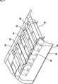
Im Fahrzeug gemäß der vorliegenden Erfindung ist der Kraftstoffgastank auf einem Dach des Fahrzeugs montiert. Daher kann der Kraftstoffgastank in einfacher Weise derart montiert werden, dass die Längsrichtung davon in der seitlichen Richtung des Fahrzeugs ist. In diesem Fall ist eine Abdeckung vorgesehen, die den Kraftstoffgastank von oben bedeckt und eine Lüftungsöffnung zur Lüftung aufweist. Weiter ist in diesem Fall die Lüftungsöffnung derart gestaltet, um einen Druck innerhalb der Abdeckung herabzusetzen, wenn der Druck innerhalb der Abdeckung plötzlich ansteigt. In the vehicle according to the present invention, the fuel gas tank is mounted on a roof of the vehicle. Therefore, the fuel gas tank can be easily mounted such that the longitudinal direction thereof is in the lateral direction of the vehicle. In this case, a cover is provided which covers the fuel gas tank from above and has a vent for ventilation. Further, in this case, the vent hole is designed to reduce a pressure inside the cover when the pressure within the cover suddenly rises.
In einer bevorzugten Ausführungsform des erfindungsgemäßen Fahrzeugs ist der Kraftstoffgastank derart montiert, dass die Plattform und die Ventilstruktur jeweils auf der einen und der anderen Seite in der seitlichen Richtung bzw. Querrichtung des Fahrzeugs angeordnet sind. Da die Plattform im allgemeinen auf einer der Querseiten des Fahrzeugs vorgesehen sind, die nicht an einem entgegenkommenden Wagen vorbeikommt, erhöht das Anordnen der Ventilstruktur an der Öffnung des Kraftstoffgastanks auf der Seite, auf der ein entgegenkommendes Fahrzeug vorbeikommt, den Einfluss der strömenden Luft durch das entgegenkommende Fahrzeug in der Nähe der Ventilstruktur. Dies kann die Verdünnung des Kraftstoffgases, das nach außerhalb über die Ventilstruktur abgegeben wird, erleichtern, und den Einfluss des abgegebenen Kraftstoffgases auf die Plattform herabsetzen.In a preferred embodiment of the vehicle according to the invention, the fuel gas tank is mounted such that the platform and the valve structure are respectively arranged on one side and the other in the lateral direction or transverse direction of the vehicle. Since the platform is generally provided on one of the lateral sides of the vehicle which does not pass by an oncoming carriage, arranging the valve structure at the opening of the fuel gas tank on the side passed by an oncoming vehicle increases the influence of the flowing air through it oncoming vehicle near the valve structure. This can facilitate the dilution of the fuel gas discharged outside via the valve structure and reduce the impact of the dispensed fuel gas on the platform.
In einer weiteren bevorzugten Ausführungsform des erfindungsgemäßen Fahrzeugs ist der Kraftstoffgastank derart montiert, dass die Ventilstruktur von der Plattform im Wesentlichen um eine Fahrzeugbreite oder mehr getrennt ist. Dies kann den Einfluss des Kraftstoffgases, das nach außerhalb durch die Öffnung für den Gaskraftstoff des Kraftstoffgastanks abgegeben worden ist, auf die Plattform herabsetzen.In a further preferred embodiment of the vehicle according to the invention, the fuel gas tank is mounted such that the valve structure is separated from the platform by substantially one vehicle width or more. This can reduce the influence of the fuel gas that has been discharged outside through the opening for the gas fuel of the fuel gas tank on the platform.
In einer weiteren bevorzugten Ausführungsform des erfindungsgemäßen Fahrzeugs ist ein Kraftstoffgastank, der die Ventilstruktur, die in der Nähe eines Frontendes an einem Ende in der Längsrichtung montiert ist, aufweist, an das Fahrzeug montiert. Dies erlaubt eine Trennung der Ventilstruktur weiter weg von der Plattform.In another preferred embodiment of the vehicle according to the invention, a fuel gas tank having the valve structure mounted in the vicinity of a front end at one end in the longitudinal direction is mounted to the vehicle. This allows separation of the valve structure farther away from the platform.
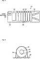
Im Fahrzeug der vorliegenden Erfindung enthält die Ventilstruktur ein Sicherheitsventil, dass Kraftstoffgas im wesentlichen senkrecht zur Längsrichtung des Kraftstoffgastanks abgibt, und der Kraftstoffgastank kann derart an das Fahrzeug montiert sein, dass eine Abgaberichtung des Kraftstoffgases vom Sicherheitsventil abwärts von einer horizontalen Position gerichtet ist. In diesem Fall kann der Kraftstoffgastank derart an das Fahrzeug montiert sein, dass das Kraftstoffgas, das vom Sicherheitsventil abgegeben wird, durch einen Fahrzeugkörper ausgebreitet bzw. zerstreut wird. Dies kann die Ausbreitung des Kraftstoffgases, das vom Sicherheitsventil abgegeben wird, erhöhen und das Kraftstoffgas verdünnen. Ferner kann der Kraftstoffgastank in diesem Fall auf einem Dach des Fahrzeugs montiert sein, und das Fahrzeug kann eine Abdeckung enthalten, die den Kraftstoffgastank von oben abdeckt und eine Lüftungsöffnung zur Lüftung aufweist.In the vehicle of the present invention, the valve structure includes a safety valve that discharges fuel gas substantially perpendicular to the longitudinal direction of the fuel gas tank, and the fuel gas tank may be mounted to the vehicle so that a discharge direction of the fuel gas from the safety valve is directed downward from a horizontal position. In this case, the fuel gas tank may be mounted to the vehicle such that the fuel gas discharged from the safety valve is diffused by a vehicle body. This can increase the spread of the fuel gas discharged from the safety valve and dilute the fuel gas. Further, in this case, the fuel gas tank may be mounted on a roof of the vehicle, and the vehicle may include a cover that covers the fuel gas tank from above and has a vent for ventilation.
KURZE BESCHREIBUNG DER ZEICHNUNGBRIEF DESCRIPTION OF THE DRAWING
BEVORZUGTE AUSFÜHRUNGSFORM DER ERFINDUNGPREFERRED EMBODIMENT OF THE INVENTION
Nachfolgend wird die beste Ausführungsform der Erfindung mit Bezug auf eine Ausführungsform beschrieben.Hereinafter, the best mode for carrying out the invention will be described with reference to an embodiment.
Eine Ventileinheit
Die Mehrzahl der Lüftungsöffnungen
Wie es in
Gemäß dem Bus
Der Bus
Beim Bus
Beim Bus
Beim Bus
Beim Bus
In der Ausführungsform wird die Beschreibung eines Verfahrens zum Montieren des Wasserstofftanks
Der Kraftstoffgastank weist im Allgemeinen eine zylindrische Struktur auf und eine Ventilstruktur als eine Öffnung für Gas ist an einem Ende in einer Längsrichtung des Kraftstoffgastanks angeordnet. In der Ausführungsform ist der Tank derart montiert, dass die Längsrichtung davon in der seitlichen Richtung des Fahrzeugs ist und derart, dass das Ende, das die Ventilstruktur aufweist, von der Plattform der Insassenkabine des Fahrzeugs getrennt ist. Anders gesagt, der Tank ist derart montiert, dass das andere Ende davon, das keine Ventilstruktur aufweist, auf der Seite der Plattform der Insassenkabine angeordnet ist.The fuel gas tank has a generally cylindrical structure, and a valve structure as an opening for gas is disposed at one end in a longitudinal direction of the fuel gas tank. In the embodiment, the tank is mounted such that the longitudinal direction thereof is in the lateral direction of the vehicle and such that the end having the valve structure is separated from the platform of the passenger cabin of the vehicle. In other words, the tank is mounted such that the other end thereof, which has no valve structure, is disposed on the side of the passenger cabin platform.
In der Ausführungsform ist der Tank derart montiert, dass die Ventilstruktur davon von der Plattform der Insassenkabine des Fahrzeugs getrennt ist, aber der Tank kann derart montiert sein, dass die Ventilstruktur davon von einem Bürgersteig auf einer Strasse, auf welcher das Fahrzeug fährt, getrennt ist. In diesem Fall kann beispielsweise, wenn es einen Bürgersteig (einen Seitenstreifen) für Fußgänger auf einem Seitenabschnitt einer Strasse mit einer oder mehr Spuren auf jeder Seite gibt, erlaubt sein, dass das Ende, das die Ventilstruktur des Tanks aufweist, an der Seite einer Mittellinie (Mitte) der Straße angeordnet ist, und das Ende, das keine Ventilstruktur des Tanks aufweist, ist auf der Seite des Bürgersteigs angeordnet. Dies kann den Einfluss auf die Fußgänger herabsetzen.In the embodiment, the tank is mounted such that the valve structure thereof is separated from the platform of the passenger cabin of the vehicle, but the tank may be mounted such that the valve structure thereof is separated from a sidewalk on a road on which the vehicle is traveling , In this case, for example, if there is a sidewalk for pedestrians on a side portion of a road having one or more lanes on each side, the end having the valve structure of the tank may be allowed to be on the side of a center line (Center) of the road is arranged, and the end, which has no valve structure of the tank is disposed on the side of the sidewalk. This can reduce the impact on pedestrians.
Die Ausführungsform und ihre vorstehend diskutierten abgewandelten Beispiele sind in allen Aspekten als beschreibend und nicht beschränkend aufzufassen. Es kann viele weitere Abwandlungen, Änderungen und Variationen geben, ohne vom Schutzumfang oder Grundgedanken der Hauptmerkmale der vorliegenden Erfindung abzuweichen.The embodiment and its modified examples discussed above are to be considered in all aspects as illustrative and not restrictive. There may be many other modifications, changes and variations without departing from the scope or spirit of the main features of the present invention.
Industrielle AnwendbarkeitIndustrial applicability
Die vorliegende Erfindung ist in der Industrie einsetzbar, die Fahrzeuge herstellt, an die ein Kraftstoffgastank montiert ist.The present invention is applicable to the industry that manufactures vehicles to which a fuel gas tank is mounted.
Claims (5)
Translated fromGermanApplications Claiming Priority (3)
| Application Number | Priority Date | Filing Date | Title |
|---|---|---|---|
| JP2005-002273 | 2005-01-07 | ||
| JP2005002273AJP4631440B2 (en) | 2005-01-07 | 2005-01-07 | Vehicle and gas fuel tank mounting method |
| PCT/JP2006/300108WO2006073193A1 (en) | 2005-01-07 | 2006-01-06 | Vehicle and method for loading gaseous fuel tank |
Publications (2)
| Publication Number | Publication Date |
|---|---|
| DE112006000144T5 DE112006000144T5 (en) | 2008-02-21 |
| DE112006000144B4true DE112006000144B4 (en) | 2016-12-29 |
Family
ID=36647670
Family Applications (1)
| Application Number | Title | Priority Date | Filing Date |
|---|---|---|---|
| DE112006000144.2TExpired - Fee RelatedDE112006000144B4 (en) | 2005-01-07 | 2006-01-06 | vehicle |
Country Status (6)
| Country | Link |
|---|---|
| US (1) | US9260009B2 (en) |
| JP (1) | JP4631440B2 (en) |
| CN (1) | CN101102914A (en) |
| BR (1) | BRPI0606407B1 (en) |
| DE (1) | DE112006000144B4 (en) |
| WO (1) | WO2006073193A1 (en) |
Cited By (2)
| Publication number | Priority date | Publication date | Assignee | Title |
|---|---|---|---|---|
| US10870361B2 (en) | 2018-08-21 | 2020-12-22 | Toyota Jidosha Kabushiki Kaisha | Vehicle structure of fuel cell vehicle |
| DE102020211938A1 (en) | 2020-09-23 | 2022-03-24 | Ford Global Technologies, Llc | Tank arrangement for a motor vehicle |
Families Citing this family (21)
| Publication number | Priority date | Publication date | Assignee | Title |
|---|---|---|---|---|
| DE102009030348A1 (en) | 2009-06-25 | 2010-12-30 | GM Global Technology Operations, Inc., Detroit | Module for a vehicle chassis comprises structural components for attaching to the module on supporting components of a vehicle chassis and integrated fuel containers for coupling with structural components to absorb collisions and/or energy |
| US9114930B2 (en)* | 2011-03-07 | 2015-08-25 | Casella Waste Systems, Inc. | Compressed natural gas vehicle apparatus and method |
| US9533569B2 (en) | 2013-06-18 | 2017-01-03 | The Heil Co. | Tailgate with structurally integrated CNG system |
| CN103770632B (en)* | 2013-12-31 | 2016-01-20 | 安徽安凯汽车股份有限公司 | A kind of air-conditioned double-layer public transport vehicle combustion gas chamber structure |
| CN103996890B (en)* | 2014-05-26 | 2016-02-10 | 唐山轨道客车有限责任公司 | For the thermal control system of tramcar |
| US9579969B2 (en)* | 2014-07-25 | 2017-02-28 | Oshkosh Corporation | Refuse vehicle having tailgate-mounted CNG tanks |
| JP6344342B2 (en)* | 2015-09-04 | 2018-06-20 | トヨタ自動車株式会社 | Fuel cell vehicle |
| JP6292205B2 (en)* | 2015-10-20 | 2018-03-14 | トヨタ自動車株式会社 | Vehicle underfloor structure |
| EP3436323A1 (en)* | 2016-04-01 | 2019-02-06 | Agility Fuel Systems LLC | Vehicle fluid handling systems |
| JP6477575B2 (en)* | 2016-04-19 | 2019-03-06 | トヨタ自動車株式会社 | Arrangement structure of peripheral information detection sensor |
| JP6561974B2 (en) | 2016-11-28 | 2019-08-21 | トヨタ自動車株式会社 | vehicle |
| US10914401B2 (en) | 2017-01-10 | 2021-02-09 | The Heil Co. | Fuel monitoring system |
| DE102018000432A1 (en) | 2018-01-19 | 2018-07-12 | Daimler Ag | Vehicle with at least one tank |
| US11207974B2 (en) | 2018-09-21 | 2021-12-28 | The Heil Co. | Multiple gas tank assembly with individual pressure monitoring |
| CN112918283B (en)* | 2019-12-05 | 2022-04-22 | 未势能源科技有限公司 | A vehicle that is used for gas bomb of vehicle and has it |
| JP7226366B2 (en) | 2020-02-12 | 2023-02-21 | トヨタ自動車株式会社 | fuel storage device |
| JP7238827B2 (en) | 2020-02-13 | 2023-03-14 | トヨタ自動車株式会社 | fuel cell vehicle |
| JP7279686B2 (en)* | 2020-05-25 | 2023-05-23 | トヨタ自動車株式会社 | Hydrogen tank storage case |
| JP7202331B2 (en) | 2020-07-20 | 2023-01-11 | 本田技研工業株式会社 | fuel cell car |
| JP7655182B2 (en)* | 2021-10-08 | 2025-04-02 | トヨタ自動車株式会社 | Hydrogen tank vehicle |
| CN114734902B (en)* | 2022-06-10 | 2022-09-02 | 中国石油大学(华东) | A small-scale natural gas hydrate storage and transportation method and intelligent device |
Citations (5)
| Publication number | Priority date | Publication date | Assignee | Title |
|---|---|---|---|---|
| DE3912623A1 (en)* | 1989-04-18 | 1990-10-25 | Schulz & Rackow Gastechnik Gmb | GAS BOTTLE VALVE |
| DE19518036C1 (en)* | 1995-05-17 | 1996-12-05 | Daimler Benz Ag | Device for refueling gas bottles of a gas-powered bus |
| JP2000225855A (en)* | 1999-02-03 | 2000-08-15 | Nissan Diesel Motor Co Ltd | Body structure of a bus equipped with a compressed natural gas engine |
| JP2001239845A (en)* | 2000-02-28 | 2001-09-04 | Mitsubishi Automob Eng Co Ltd | Vehicle fuel gas cylinder mounting structure |
| DE60006898T2 (en)* | 1999-06-17 | 2004-10-28 | Kai Motors Corp. | LPG tank assembly for vehicle |
Family Cites Families (8)
| Publication number | Priority date | Publication date | Assignee | Title |
|---|---|---|---|---|
| US3213821A (en)* | 1964-03-10 | 1965-10-26 | Vincent R Godwin | Convertible hydromobile |
| US3430647A (en)* | 1966-06-10 | 1969-03-04 | Turner Corp | Safety valve for propane cylinders |
| US5309972A (en)* | 1991-02-25 | 1994-05-10 | Thomas Allen C | Air vent cover |
| JP3596277B2 (en)* | 1998-02-27 | 2004-12-02 | 三菱ふそうトラック・バス株式会社 | vehicle |
| JP3672445B2 (en) | 1998-10-22 | 2005-07-20 | 日産ディーゼル工業株式会社 | Body structure of a bus with a compressed natural gas engine |
| JP2000170606A (en)* | 1998-12-03 | 2000-06-20 | Hino Motors Ltd | Fuel gas piping structure for automobile |
| US6367573B1 (en)* | 1999-09-20 | 2002-04-09 | Fab Industries, Llc | Cylinder mount for fuel system |
| JP3791383B2 (en)* | 2001-10-10 | 2006-06-28 | 日産自動車株式会社 | Fuel tank mounting structure for fuel cell vehicles |
- 2005
- 2005-01-07JPJP2005002273Apatent/JP4631440B2/ennot_activeExpired - Fee Related
- 2006
- 2006-01-06USUS11/794,095patent/US9260009B2/ennot_activeExpired - Fee Related
- 2006-01-06CNCNA2006800019336Apatent/CN101102914A/enactivePending
- 2006-01-06DEDE112006000144.2Tpatent/DE112006000144B4/ennot_activeExpired - Fee Related
- 2006-01-06WOPCT/JP2006/300108patent/WO2006073193A1/enactiveApplication Filing
- 2006-01-06BRBRPI0606407-8Apatent/BRPI0606407B1/ennot_activeIP Right Cessation
Patent Citations (5)
| Publication number | Priority date | Publication date | Assignee | Title |
|---|---|---|---|---|
| DE3912623A1 (en)* | 1989-04-18 | 1990-10-25 | Schulz & Rackow Gastechnik Gmb | GAS BOTTLE VALVE |
| DE19518036C1 (en)* | 1995-05-17 | 1996-12-05 | Daimler Benz Ag | Device for refueling gas bottles of a gas-powered bus |
| JP2000225855A (en)* | 1999-02-03 | 2000-08-15 | Nissan Diesel Motor Co Ltd | Body structure of a bus equipped with a compressed natural gas engine |
| DE60006898T2 (en)* | 1999-06-17 | 2004-10-28 | Kai Motors Corp. | LPG tank assembly for vehicle |
| JP2001239845A (en)* | 2000-02-28 | 2001-09-04 | Mitsubishi Automob Eng Co Ltd | Vehicle fuel gas cylinder mounting structure |
Non-Patent Citations (4)
| Title |
|---|
| Alwin Berti: Der neue MAN Brennstoffzellenbus. In: http://www.brennstoffzellenbus.de/bus2004/bsz04-1d.htm, Mai, 2004, http://www.brennstoffzellenbus.de/bus2004/bsz04-3d.htm [abgerufen am 11.12.2013]* |
| H2Mobility: Hydrogen Vehicles. In: http://www.hyweb.de/, unbekannt, http://www.netinform.net/h2/H2Mobility/Default.aspx [abgerufen am 11.12.2013]* |
| Schuckert, Manfred: The CUTE hydrogen fuel cell bus demonstration project - an Update. In: CUTE, 17.6.2003, 7. ftp://ftp.cordis.europa.eu/pub/sustdev/docs/energy/sustdev_h2_sessionb_schuckert.pdf/ [abgerufen am 11.12.2013]* |
| Wurster, R. et al.: Fuel Cell Propulsion for Urban Duty Vehicles - Bavarian Fuel Cell Bus Project. In: the 12. World Hydrogen Energy Conference, Buenos Aires, Argentina, .June 1998, Juni, 1998, 1-8. http://www.netinform.de/H2/files/pdf/Bavarian_Fuel_Cell_Bus_Project.pdf [abgerufen am 12.12.2013]* |
Cited By (4)
| Publication number | Priority date | Publication date | Assignee | Title |
|---|---|---|---|---|
| US10870361B2 (en) | 2018-08-21 | 2020-12-22 | Toyota Jidosha Kabushiki Kaisha | Vehicle structure of fuel cell vehicle |
| DE102019121250B4 (en) | 2018-08-21 | 2024-07-18 | Toyota Jidosha Kabushiki Kaisha | Vehicle structure for a fuel cell vehicle |
| DE102020211938A1 (en) | 2020-09-23 | 2022-03-24 | Ford Global Technologies, Llc | Tank arrangement for a motor vehicle |
| US12128758B2 (en) | 2020-09-23 | 2024-10-29 | Ford Global Technologies, Llc | Tank assembly for a motor vehicle |
Also Published As
| Publication number | Publication date |
|---|---|
| US9260009B2 (en) | 2016-02-16 |
| BRPI0606407B1 (en) | 2019-10-08 |
| JP4631440B2 (en) | 2011-02-16 |
| DE112006000144T5 (en) | 2008-02-21 |
| WO2006073193A1 (en) | 2006-07-13 |
| CN101102914A (en) | 2008-01-09 |
| US20080156809A1 (en) | 2008-07-03 |
| JP2006188169A (en) | 2006-07-20 |
| BRPI0606407A2 (en) | 2009-06-23 |
Similar Documents
| Publication | Publication Date | Title |
|---|---|---|
| DE112006000144B4 (en) | vehicle | |
| DE102020131112A1 (en) | Cooling arrangement for battery flooding, motor vehicle and method for cooling at least one battery cell | |
| DE102021112231A1 (en) | Degassing duct, battery assembly and motor vehicle | |
| DE102020131110A1 (en) | Motor vehicle and cooling arrangement for a motor vehicle with a high-voltage battery for protecting occupants in the event of a battery fire | |
| DE102021132479A1 (en) | Battery arrangement and method for removing a gas from a battery cell | |
| DE102021204370B4 (en) | Accumulator arrangement for a motor vehicle and motor vehicle with an accumulator arrangement | |
| DE102021102908A1 (en) | Degassing device, battery and motor vehicle | |
| EP4052765A1 (en) | Motor vehicle and method for introducing an extinguishing agent into a battery | |
| DE102021111763A1 (en) | Battery arrangement with an extinguishing agent supply device, motor vehicle and method for protecting a battery | |
| DE102021104940A1 (en) | Battery arrangement, motor vehicle and method for removing gases from a battery | |
| DE102018200354A1 (en) | Assembly for a motor vehicle | |
| EP3617040A1 (en) | Driver's cab front module and method for producing a driver's cab | |
| WO2014195177A1 (en) | Rail vehicle with deformation zone | |
| DE102013018408A1 (en) | Battery with a plurality of battery cells | |
| DE102021127619A1 (en) | Cell degassing duct, battery arrangement and method for removing gases from a battery | |
| DE102010016743B4 (en) | motor vehicle | |
| DE102018130070B4 (en) | Electrically or partially electrically driven vehicle | |
| DE102020131108A1 (en) | Battery arrangement, motor vehicle and method for flooding a high-voltage battery | |
| DE10154026A1 (en) | Motor vehicle comprises a front engine space containing a deformation element arranged in front of a drive device, and a passenger compartment separated from the rear of the engine space by a front wall | |
| DE102007019078B4 (en) | Roof-mounted air conditioning | |
| DE202020102000U1 (en) | Range enlarger | |
| DE102022104368A1 (en) | Motor vehicle with an extinguishing device and method for supplying an extinguishing agent to an energy store of a motor vehicle | |
| DE102021120073A1 (en) | Motor vehicle with a battery arrangement and method for dropping a battery unit from a motor vehicle | |
| EP4169773A1 (en) | Device for climbing a motor vehicle | |
| EP1736344B1 (en) | Accessory unit including emergency roof hatch |
Legal Events
| Date | Code | Title | Description |
|---|---|---|---|
| OP8 | Request for examination as to paragraph 44 patent law | ||
| R016 | Response to examination communication | ||
| R016 | Response to examination communication | ||
| R016 | Response to examination communication | ||
| R018 | Grant decision by examination section/examining division | ||
| R020 | Patent grant now final | ||
| R084 | Declaration of willingness to licence | ||
| R119 | Application deemed withdrawn, or ip right lapsed, due to non-payment of renewal fee |