DE102023207295A1 - waveguide-based imaging system - Google Patents
waveguide-based imaging systemDownload PDFInfo
- Publication number
- DE102023207295A1 DE102023207295A1DE102023207295.5ADE102023207295ADE102023207295A1DE 102023207295 A1DE102023207295 A1DE 102023207295A1DE 102023207295 ADE102023207295 ADE 102023207295ADE 102023207295 A1DE102023207295 A1DE 102023207295A1
- Authority
- DE
- Germany
- Prior art keywords
- imaging system
- waveguide
- light
- pair
- partially
- Prior art date
- Legal status (The legal status is an assumption and is not a legal conclusion. Google has not performed a legal analysis and makes no representation as to the accuracy of the status listed.)
- Pending
Links
- 238000003384imaging methodMethods0.000titleclaimsabstractdescription137
- 230000008878couplingEffects0.000claimsabstractdescription45
- 238000010168coupling processMethods0.000claimsabstractdescription45
- 238000005859coupling reactionMethods0.000claimsabstractdescription45
- 230000005484gravityEffects0.000claimsdescription11
- 238000000034methodMethods0.000claimsdescription8
- 238000004519manufacturing processMethods0.000claimsdescription3
- 230000003595spectral effectEffects0.000description29
- 238000001514detection methodMethods0.000description14
- 238000009826distributionMethods0.000description9
- 239000003086colorantSubstances0.000description8
- 239000010410layerSubstances0.000description6
- 230000003287optical effectEffects0.000description6
- 230000008092positive effectEffects0.000description5
- 230000001419dependent effectEffects0.000description4
- 239000011241protective layerSubstances0.000description4
- 238000005549size reductionMethods0.000description4
- 230000008901benefitEffects0.000description3
- 230000001427coherent effectEffects0.000description3
- 230000000694effectsEffects0.000description3
- 150000004820halidesChemical class0.000description3
- 230000003993interactionEffects0.000description3
- 230000008569processEffects0.000description3
- 241001136792AlleSpecies0.000description2
- 230000005540biological transmissionEffects0.000description2
- 230000008859changeEffects0.000description2
- 238000006243chemical reactionMethods0.000description2
- 239000011521glassSubstances0.000description2
- 230000001788irregularEffects0.000description2
- 239000005340laminated glassSubstances0.000description2
- 238000012545processingMethods0.000description2
- 238000001228spectrumMethods0.000description2
- JKFYKCYQEWQPTM-UHFFFAOYSA-N2-azaniumyl-2-(4-fluorophenyl)acetateChemical compoundOC(=O)C(N)C1=CC=C(F)C=C1JKFYKCYQEWQPTM-UHFFFAOYSA-N0.000description1
- 101100229963Drosophila melanogaster grau geneProteins0.000description1
- 108010010803GelatinProteins0.000description1
- 229910021607Silver chlorideInorganic materials0.000description1
- 229910021612Silver iodideInorganic materials0.000description1
- 238000010521absorption reactionMethods0.000description1
- 230000004075alterationEffects0.000description1
- 230000009286beneficial effectEffects0.000description1
- 239000011248coating agentSubstances0.000description1
- 238000000576coating methodMethods0.000description1
- 239000002131composite materialSubstances0.000description1
- 239000012141concentrateSubstances0.000description1
- 238000010276constructionMethods0.000description1
- 230000001066destructive effectEffects0.000description1
- 239000000839emulsionSubstances0.000description1
- 238000000605extractionMethods0.000description1
- 230000002349favourable effectEffects0.000description1
- 238000001914filtrationMethods0.000description1
- 125000000524functional groupChemical group0.000description1
- 229920000159gelatinPolymers0.000description1
- 239000008273gelatinSubstances0.000description1
- 235000019322gelatineNutrition0.000description1
- 235000011852gelatine dessertsNutrition0.000description1
- 238000003702image correctionMethods0.000description1
- 238000009434installationMethods0.000description1
- 239000000463materialSubstances0.000description1
- 230000007935neutral effectEffects0.000description1
- 238000005457optimizationMethods0.000description1
- 229920000642polymerPolymers0.000description1
- 238000012805post-processingMethods0.000description1
- 230000008707rearrangementEffects0.000description1
- 230000009467reductionEffects0.000description1
- 239000011347resinSubstances0.000description1
- 229920005989resinPolymers0.000description1
- 229910052709silverInorganic materials0.000description1
- 239000004332silverSubstances0.000description1
- ADZWSOLPGZMUMY-UHFFFAOYSA-Msilver bromideChemical compound[Ag]BrADZWSOLPGZMUMY-UHFFFAOYSA-M0.000description1
- 229940045105silver iodideDrugs0.000description1
- HKZLPVFGJNLROG-UHFFFAOYSA-Msilver monochlorideChemical compound[Cl-].[Ag+]HKZLPVFGJNLROG-UHFFFAOYSA-M0.000description1
- 239000007787solidSubstances0.000description1
Images


Classifications
- G—PHYSICS
- G02—OPTICS
- G02B—OPTICAL ELEMENTS, SYSTEMS OR APPARATUS
- G02B17/00—Systems with reflecting surfaces, with or without refracting elements
- G02B17/008—Systems specially adapted to form image relays or chained systems
- G—PHYSICS
- G02—OPTICS
- G02B—OPTICAL ELEMENTS, SYSTEMS OR APPARATUS
- G02B27/00—Optical systems or apparatus not provided for by any of the groups G02B1/00 - G02B26/00, G02B30/00
- G02B27/01—Head-up displays
- G02B27/017—Head mounted
- G02B27/0172—Head mounted characterised by optical features
- G—PHYSICS
- G02—OPTICS
- G02B—OPTICAL ELEMENTS, SYSTEMS OR APPARATUS
- G02B27/00—Optical systems or apparatus not provided for by any of the groups G02B1/00 - G02B26/00, G02B30/00
- G02B27/42—Diffraction optics, i.e. systems including a diffractive element being designed for providing a diffractive effect
- G02B27/4272—Diffraction optics, i.e. systems including a diffractive element being designed for providing a diffractive effect having plural diffractive elements positioned sequentially along the optical path
Landscapes
- Physics & Mathematics (AREA)
- General Physics & Mathematics (AREA)
- Optics & Photonics (AREA)
- Diffracting Gratings Or Hologram Optical Elements (AREA)
- Holo Graphy (AREA)
Abstract
Translated fromGerman
Description
Translated fromGerman1. Technisches Gebiet1. Technical area
Die vorliegende Erfindung betrifft wellenleiterbasierte Abbildungssysteme, z.B. für RGB-Holocams. Beispiele der Erfindung sind Abbildungssysteme, die auf beugungsbasierten Einkopplungselementen zur Einkopplung von auf die Einkopplungselemente auftreffendem Licht in einen Wellenleiter basieren.The present invention relates to waveguide-based imaging systems, e.g. for RGB holocams. Examples of the invention are imaging systems based on diffraction-based coupling elements for coupling light incident on the coupling elements into a waveguide.
2. Stand der Technik2. State of the art
Beugungsbasierte optische Elemente, wie z.B. Gitter oder Hologramme, werden bevorzugt dazu eingesetzt, auf Wellenleiter auftreffendes Licht innerhalb des Wellenleiters umzulenken. So können z.B. maßgeschneiderte Abbildungssysteme erstellt werden.Diffraction-based optical elements, such as gratings or holograms, are preferably used to redirect light incident on waveguides within the waveguide. This allows, for example, tailor-made imaging systems to be created.
Obwohl eine vielfältige Ausgestaltung des Wellenleiters vorliegen kann, kann er für manche Anwendungen z.B. in Form einer oder mehrerer Scheiben ausgeführt sein, oder in diese integriert sein. Das Beispiel mehrerer Scheiben kann z.B. Verbundglas umfassen, das mindestens zwei Glasscheiben umfassen kann, die z.B. jeweils durch eine Zwischenschicht, z. B. aus Kunststoff, Gießharz und/oder einer Verbundfolie, miteinander verbunden sein können. Zum Beispiel kann so an einer ersten Position auf den Wellenleiter (z.B. eine Scheibe) auftreffendes Licht intern über den Wellenleiter an eine andere, zweite Position des Wellenleiters (z.B. der Scheibe) geführt werden, von wo es dann z.B. auf eine Kamera und/oder einen Bildsensor gelenkt werden kann. Somit kann z.B. die Kamera an einer Position angeordnet werden, die von der ersten Position verschieden ist, und an der sie z.B. nach außen hin nicht sichtbar ist.Although the waveguide can be designed in a variety of ways, for some applications it can be designed in the form of one or more panes, for example, or integrated into them. The example of multiple panes can include, for example, laminated glass, which can include at least two panes of glass, which can each be connected to one another, for example, by an intermediate layer, e.g. made of plastic, cast resin and/or a composite film. For example, light striking the waveguide (e.g. a pane) at a first position can be guided internally via the waveguide to another, second position of the waveguide (e.g. the pane), from where it can then be directed, for example, to a camera and/or an image sensor. Thus, for example, the camera can be arranged in a position that is different from the first position and at which it is not visible from the outside, for example.
Beugungsbasierte optische Elemente können dabei eine Winkelabhängigkeit in der spektralen Verteilung des umgelenkten Lichts aufweisen. Werden beugungsbasierte Elemente zum Einsammeln von Licht in Abbildungssystemen eingesetzt, kann sich daher in manchen Fällen nur in einem kleinen Bereich des prinzipiell verfügbaren Gesichtsfelds, FOV, der beugungsbasierten Elemente eine farbgetreue Abbildung des Abbildungssystems einstellen. Bei Lichteinfallswinkeln, die außerhalb dieses Bereichs des FOV liegen, kann es zu winkelabhängigen Blau- oder Rotverschiebungen kommen: Beugungsbasierte optische Elemente haben typischerweise ein FOV, das den Raumwinkelbereich umfasst, aus dem einfallendes Licht vom optischen Element aufgenommen und/oder umgelenkt werden kann. Dies kann im Wesentlichen bei einer Wellenlänge gut funktionieren. Z.B. monochromatische Hologramme sind dazu eingerichtet Licht einer bestimmten Wellenlänge in einem bestimmten Winkel umzulenken, wenn es aus einer vorbestimmten Richtung kommt, z.B. entlang einer zentralen Richtung des FOV. Wenn die Einfallrichtung des Lichts aber von der vorbestimmten Richtung abweicht, kann im Beispiel eines Hologramms statt der eigentlichen Farbe, auf die das Hologramm ausgerichtet ist, eine andere entlang der vorbestimmten Richtung umgelenkt werden. Wird ein solches beugungsbasiertes Element in Abbildungssystemen eingesetzt, können sich ungewollte spektrale Winkelabhängigkeiten ergeben: Winkelabhängig kann nur ein Teil des vollständigen Spektrums abgebildet werden, sodass Spektralbereiche fehlen. Im Ergebnis können damit in Abbildungen andere Farben als gewünscht abgebildet werden. Bei RGBoptischen Elementen kann aufgrund dieses Effekts in einem Teil des FOV eine Weißlichtabbildung erstellt werden bzw. das komplette Spektrum vorhanden sein, an den Rändern des FOV kann es jedoch zu stärkeren Rot- oder Blauverschiebungen kommen.Diffraction-based optical elements can exhibit an angle dependence in the spectral distribution of the redirected light. If diffraction-based elements are used to collect light in imaging systems, in some cases a true-color image of the imaging system can only be achieved in a small area of the basically available field of view, FOV, of the diffraction-based elements. At angles of incidence of light that lie outside this area of the FOV, angle-dependent blue or red shifts can occur: Diffraction-based optical elements typically have an FOV that covers the solid angle range from which incident light can be absorbed and/or redirected by the optical element. This can essentially work well at one wavelength. For example, monochromatic holograms are designed to redirect light of a certain wavelength at a certain angle when it comes from a predetermined direction, e.g. along a central direction of the FOV. However, if the direction of incidence of the light deviates from the predetermined direction, in the example of a hologram, instead of the actual color to which the hologram is aligned, another color can be redirected along the predetermined direction. If such a diffraction-based element is used in imaging systems, unwanted spectral angle dependencies can arise: Depending on the angle, only part of the complete spectrum can be imaged, so that spectral ranges are missing. As a result, different colors than desired can be imaged in images. With RGB optical elements, this effect can create a white light image in part of the FOV or the complete spectrum can be present, but stronger red or blue shifts can occur at the edges of the FOV.
Der vorliegenden Erfindung liegt daher die Aufgabe zu Grunde entsprechende Abbildungssystem, Systeme und zugehörige Verfahren zumindest teilweise zu verbessern.The present invention is therefore based on the object of at least partially improving corresponding imaging systems, systems and associated methods.
3. Zusammenfassung der Erfindung3. Summary of the invention
Diese Aufgabe wird durch die hierin beschriebenen Aspekte zumindest teilweise gelöst.This task is at least partially solved by the aspects described herein.
Ein erster Aspekt betrifft ein Abbildungssystem umfassend einen Wellenleiter und zumindest zwei beugungsbasierte Einkopplungselemente, EE. Die zumindest zwei EE sind dazu eingerichtet, auf die EE auftreffendes Licht zumindest teilweise innerhalb des Wellenleiters umzulenken, wobei die zumindest zwei EE relativ zueinander in einem Verkippungswinkel von ungleich 0° verkippt sind.A first aspect relates to an imaging system comprising a waveguide and at least two diffraction-based coupling elements, EE. The at least two EE are designed to at least partially redirect light incident on the EE within the waveguide, wherein the at least two EE are tilted relative to one another at a tilt angle of not equal to 0°.
Das Abbildungssystem mit mehreren EE, jeweils mit einem FOV, weist im Vergleich zu Abbildungssystemen mit nur einem EE ein vergrößertes FOV auf und entkoppelt zudem die spektrale Winkelabhängigkeit des umgelenkten Lichts der gegeneinander verkippten EE zumindest teilweise, wie hierin beschrieben. Damit kann die Farbqualität und -echtheit der Bilder, die durch das Abbildungssystem aufgenommen werden können, verbessert werden. Der nutzbare Bereich des FOV des Abbildungssystems kann so erweitert werden.The imaging system with multiple EE, each with an FOV, has an enlarged FOV compared to imaging systems with only one EE and also decouples the spectral angle dependence of the deflected light of the EE tilted against each other at least partially, as described herein. This can improve the color quality and authenticity of the images that can be recorded by the imaging system. The usable range of the FOV of the imaging system can thus be expanded.
Das allgemeine Prinzip soll anhand der nachfolgenden
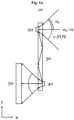
Die
Das EE 20 hat ein vertikales Gesichtsfeld, v-FOV. Das aus dem v-FOV einfallende Licht wird vom EE 20 in den Wellenleiter 30 umgelenkt, wie durch die schwarzen Pfeile schematisch dargestellt. Innerhalb des Wellenleiters gelangt das umgelenkte Licht über Totalreflexion zum AE 40. In anderen Ausführungsbeispielen kann das Licht z.B. auch in mehr, weniger oder sogar ganz ohne Reflexionen innerhalb des Wellenleiters 30 zum AE 40 gelangen. Das EE 20, der Wellenleiter 30 und das AE 40 sind in ihrer jeweiligen Form, Ausdehnung, relativen Position und/oder relativen Orientierung so aufeinander abgestimmt, dass das umgelenkte Licht vom EE 20 möglichst effizient zum AE 40 gelangt, von wo das umgelenkte Licht zum Detektionssystem 50 zumindest teilweise ausgekoppelt wird, wie durch die schwarzen Pfeile schematisch dargestellt.The
Das v-FOV umfasst einen Öffnungswinkel αv, wobei αv = 0 in dem Beispiel von
Grundsätzlich kann die Umlenkung des Lichts durch das EE 20 und das AE 40 vom Einfallwinkel des ankommenden Lichts z.B. insofern abhängen, als dass der Umlenkwinkel und/oder die spektrale Verteilung des umgelenkten Lichts vom Einfallwinkel abhängt und/oder nur ein Teil des Lichts das AE 40 erreicht.In principle, the deflection of light by the
Abbildungssysteme wie in
1d zeigt schematisch die spektrale Verteilung des umgelenkten Lichts dreier paralleler Hologramme H3 (rot), H2 (grün), H1 (blau) über das gesamte FOV der drei Hologramme H1, H2, H3. Die zugrundeliegende Anordnung der Hologramme H1, H2, H3 kann beispielsweise parallele Hologramme H1, H2, H3 umfassen, die entlang einer Achse, z.B. senkrecht zur Erstreckung der Hologramme H1, H2, H3 zueinander parallelverschoben sind.
1d shows schematically the spectral distribution of the deflected light of three parallel holograms H3 (red), H2 (green), H1 (blue) over the entire FOV of the three holograms H1, H2, H3. The underlying arrangement of the holograms H1, H2, H3 can, for example, comprise parallel holograms H1, H2, H3 that are shifted parallel to one another along an axis, e.g. perpendicular to the extension of the holograms H1, H2, H3.
Die Hologramme H1, H2, H3 sind monochromatische Hologramme. Hologramm H1 wurde mit blauem Licht belichtet und ist dazu eingerichtet, blaues Licht, das in einem Winkel αv = 0 auf das Hologramm H1 trifft, unter einem vorgegebenen Umlenkwinkel umzulenken. Wie aus
Gleiches lässt sich analog auf die Hologramme H2 für grünes Licht und H3 für rotes Licht übertragen. Das entlang einer bestimmten Richtung umgelenkte Licht erfährt mit av > 0 eine Rotverschiebung und für αv < 0 eine Blauverschiebung. Der Winkel αv stellt den vertikalen Winkel des FOV der Hologramme dar und ist in
Die drei einzelnen Hologramme H1, H2, H3 lassen sich ebenso in ein gemeinsames RGB-Hologramm S schreiben, das die gleiche spektrale Winkelabhängigkeit aufweist. Ferner stellt S das Zusammenwirken der Hologramme H1, H2, H3 schematisch dar:
- Die spektrale Superposition S des umgelenkten Lichts aller drei Hologramme H1, H2, H3 (bzw. eines entsprechenden RGB-Hologramms) folgt direkt aus der hierin beschriebenen spektralen Winkelabhängigkeit: Für das Geschichtsfeld im Bereich αv > 0 fehlt der blaue Spektralbereich und für αv < 0 der rote Spektralbereich. Das FOV kann grundsätzlich neben Winkelkoordinaten auch z.B. in kartesischen Koordinaten beschrieben werden, z.B. um eine Position innerhalb des FOV durch eine Position/Strecke zu bestimmen. Konventionell wäre die Achsenrichtung der vertikalen kartesischen Achse in
1d gegenläufig zur Richtung des Winkels αv in1d .
- The spectral superposition S of the deflected light of all three holograms H1, H2, H3 (or a corresponding RGB hologram) follows directly from the spectral angle dependence described here: For the field of view in the range αv > 0 the blue spectral range is missing and for αv < 0 the red spectral range is missing. In principle, the FOV can be described in Cartesian coordinates in addition to angular coordinates, e.g. to determine a position within the FOV by a position/distance. Conventionally, the axis direction of the vertical Cartesian axis would be in
1d opposite to the direction of the angle αv in1d .
In Bezug auf das Abbildungssystem 10 der
Dieses Problem haben die Erfinder erkannt und mit den hierin beschriebenen Aspekten zumindest teilweise behoben, wie beispielhaft anhand der
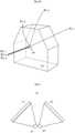
2a zeigtein beispielhaftes Abbildungssystems 10 mit drei gegeneinander verkipptenEE EE der EE - Insgesamt kann also die Größe des FOV sowie der Anteil des FOV, in dem Abbildungen mit reduzierten spektralen Verschiebungen möglich sind, vergrößert werden.
2a shows anexemplary imaging system 10 with threeEE EE - Overall, the size of the FOV as well as the portion of the FOV in which images with reduced spectral shifts are possible can be increased.
Die drei EE 21, 22, 23 weisen jeweils, ähnlich wie in
- Durch die Verkippung weist die spektrale Superposition S des umgelenkten Lichts aller drei Hologramme H1, H2, H3 nicht nur (wie in
1d ) einen zentralen Streifen auf, in dem alle drei Farben und damit Weißlicht vorhanden ist, sondern drei, zueinander um 60° verkippte, Streifen decken einen großen Bereich des FOVs ab, über den alle drei Farben (rot, grün, blau) gemäß der Belichtung der Hologramme entlang der Richtung des vorgegebenen Umlenkwinkels umgelenkt werden. Lediglich in den Ecken des sechseckigen FOV liegen Zonen, in denen Farbfehler vorliegen:- Die gestrichelt umrandeten rautenförmigen Bereiche in den Ecken auf der linken und rechten Seite des Sechsecks stellen Bereiche dar, in denen rotes und blaues, jedoch kein grünes Licht umgelenkt wird. Dort kann allerdings dann mittels Weißabgleich rekalibriert werden. Der Weißabgleich kann z.B. einen der Aufnahme nachgelagerten (z.B. digitalen) Bildbearbeitungsprozess umfassen, bei dem insbesondere bestimmt wird, welche Messwerte neutralem Weiß und/oder Grau entsprechen, wodurch z.B. unerwünschte Farbstiche vermieden werden können.
- Due to the tilting, the spectral superposition S of the deflected light of all three holograms H1, H2, H3 not only has (as in
1d ) a central strip in which all three colors and thus white light are present, but three strips tilted by 60° to each other cover a large area of the FOV, over which all three colors (red, green, blue) are deflected according to the exposure of the holograms along the direction of the specified deflection angle. Only in the corners of the hexagonal FOV are there zones in which color errors are present:- The dashed diamond-shaped areas in the corners on the left and right The other side of the hexagon represents areas in which red and blue, but not green, light is redirected. However, this can be recalibrated using white balance. White balance can, for example, include a post-image processing process (eg digital) that determines which measured values correspond to neutral white and/or gray, which can, for example, prevent undesirable color casts.
Die oberhalb direkt daran angrenzenden Bereiche des FOV stellen die Bereiche dar, aus denen einfallendes Licht rotverschoben abgebildet wird und die unterhalb direkt daran angrenzenden Bereiche stellen die Bereiche dar, aus denen einfallendes Licht blauverschoben abgebildet wird.The areas of the FOV directly above represent the areas from which incident light is imaged red-shifted, and the areas directly below represent the areas from which incident light is imaged blue-shifted.
Fällt Licht unter einem Winkel ein, der der unteren Ecke des sechseckigen FOV entspricht, so erfährt die Abbildung hier eine Rotverschiebung. Fällt Licht unter einem Winkel ein, der der oberen Ecke des sechseckigen FOV entspricht, so erfährt die Abbildung hier eine Blauverschiebung.If light falls at an angle corresponding to the bottom corner of the hexagonal FOV, the image here will be redshifted. If light falls at an angle corresponding to the top corner of the hexagonal FOV, the image here will be blueshifted.
Allgemein kann somit durch die Verkippung der Hologramme H1, H2, H3 der Bereich, in dem alle Farben geeignet umgelenkt werden im Vergleich zur parallelen Anordnung aus
Die Verkippung der Hologramme kann in manchen Beispielen damit einhergehen, dass die Strahlenverläufe (z.B. die Zentralstrahlen) zwischen zwei EE und dem jeweils zugehörigen AE nicht parallel sind. Die Verkippung kann sich also auch auf eine Verkippung z.B. eines Zentralstrahls von einem ersten EE zu einem AE gegenüber einem Zentralstrahl von einem zweiten EE zum AE (oder zu einem andere AE) beziehen. In manchen Beispielen können die Zentralstrahlen zwar verkippt sein, aber immer noch im Wesentlichen in einer Ebene liegen.In some examples, the tilting of the holograms can be associated with the fact that the ray paths (e.g. the central rays) between two EE and the respective associated AE are not parallel. The tilting can therefore also refer to a tilting of, for example, a central ray from a first EE to an AE compared to a central ray from a second EE to the AE (or to another AE). In some examples, the central rays can be tilted, but still essentially lie in one plane.
Beugungsbasierte EE können allgemein dazu eingerichtet sein, Licht, das auf die EE trifft, z.B. ausgesandt von einem Objekt, das abgebildet werden soll, zumindest teilweise in den Wellenleiter umzulenken, wo es z.B. über (Total)Reflexion weitergeleitet werden kann. Das Umlenken kann eine reine Richtungsänderung des Lichts und/oder z.B. ein Fokussieren, Kollimieren und/oder Streuen des einfallenden Lichts umfassen. Diese Beeinflussung des Lichts kann als Ganzes von einem Element eines EE erreicht werden oder ein EE kann mehrere Bestandteile umfassen, die jeweils eine der Beeinflussungen bestimmt. Die EE können z.B. eine transmissive oder reflektive diffraktive Struktur, ein transmissives oder reflektives Volumenhologramm, eine Spiegelfläche, ein Prisma und/oder ein transmissives oder reflektives Reliefgitter umfassen.Diffraction-based EEs can generally be designed to at least partially redirect light that hits the EE, e.g. emitted by an object that is to be imaged, into the waveguide, where it can be transmitted, e.g. via (total) reflection. The redirection can comprise a pure change in the direction of the light and/or, e.g., focusing, collimating and/or scattering of the incident light. This influencing of the light can be achieved as a whole by one element of an EE, or an EE can comprise several components, each of which determines one of the influences. The EE can comprise, e.g., a transmissive or reflective diffractive structure, a transmissive or reflective volume hologram, a mirror surface, a prism and/or a transmissive or reflective relief grating.
Die EE können z.B. an einer Außenseite des Wellenleiters angebracht sein, in den Wellenleiter integriert sein usw. Die EE können auf verschiedenen Seiten oder der gleichen Seite des Wellenleiters angebracht sein. Zudem kann eine Schutzschicht zum Schutz der EE auf der Seite der EE angebracht sein, die dem Wellenleiter abgewandt ist. Eine solche Schutzschicht kann z.B. im Wesentlichen die ganze Oberfläche des Wellenleiters abdecken, nur Teile davon oder nur genau die EE. Die EE können ein zumindest teilweise überlappendes FOV aufweisen, wodurch sie überhaupt erst als Komponenten eines (einzigen) Abbildungssystems gesehen werden können.The EE can, for example, be attached to an outer side of the waveguide, be integrated into the waveguide, etc. The EE can be attached to different sides or the same side of the waveguide. In addition, a protective layer to protect the EE can be attached to the side of the EE that faces away from the waveguide. Such a protective layer can, for example, cover essentially the entire surface of the waveguide, only parts of it, or only the EE. The EE can have an at least partially overlapping FOV, which allows them to be seen as components of a (single) imaging system.
Der Wellenleiter kann jedes beliebige Medium umfassen, dass grundsätzlich geeignet ist Licht mindestens einer Wellenlänge weiterzuleiten. Er kann z.B. weitere Funktionen erfüllen, z.B. als Bildschirm, Fenster, Windschutzscheibe eines Fahrzeugs usw. Der Wellenleiter kann damit einen im Wesentlichen transparenten Basiskörper bereitstellen, an dem die EE angebracht sein können. Der Wellenleiter kann z.B. Glas oder Kunststoff aufweisen.The waveguide can comprise any medium that is fundamentally suitable for transmitting light of at least one wavelength. It can, for example, fulfil other functions, e.g. as a screen, window, windshield of a vehicle, etc. The waveguide can thus provide an essentially transparent base body to which the EE can be attached. The waveguide can, for example, comprise glass or plastic.
Es gibt verschiedene, in verschiedenen beispielhaften Ausführungsformen äquivalente Möglichkeiten, einen Verkippungswinkel von zwei EE relativ zueinander zu definieren:
- Die Verkippung der EE zueinander kann sich wie hierin beschrieben darauf beziehen, dass die EE in einer Ebene der Wellenleiteroberfläche verkippt sind. Das kann z.B. eine Verkippung um eine Rotationsachse umfassen, wobei die Rotationsachse senkrecht auf der Wellenleiteroberfläche an der Position des jeweiligen EE steht und/oder senkrecht zur Oberfläche des entsprechenden EE. Diese Definition des Verkippungswinkels kann z.B. für ebene Wellenleiter ausreichend sein.
- The tilting of the EE relative to one another can, as described herein, refer to the EE being tilted in a plane of the waveguide surface. This can, for example, comprise a tilting about a rotation axis, wherein the rotation axis is perpendicular to the waveguide surface at the position of the respective EE and/or perpendicular to the surface of the corresponding EE. This definition of the tilt angle can, for example, be sufficient for planar waveguides.
In manchen Beispielen ist es auch denkbar, dass die Verkippung über die Funktionalität der EE definiert werden kann, z.B. bei gekrümmten, unregelmäßigen und/oder in ihrer Dicke variablen Wellenleitern: Weisen die EE, wie hierin beschrieben z.B. ein Hologramm auf, das z.B. durch zwei Belichtungen aus zwei verschiedenen Richtungen geschrieben wird, so definiert die erste Belichtung eine erste Richtung: Trifft Licht aus dieser ersten Richtung auf das EE, wird es entlang der Richtung der zweiten Belichtung vom EE umgelenkt. Diese beiden Richtungen spannen eine Raumebene auf, was erlaubt eine charakteristische Achse für das EE zu definieren, die senkrecht auf der Ebene steht, in der die erste und zweite Belichtung des Hologramms des EE liegen. Die Verkippung zweier EE kann dann in der relativen Verkippung der zwei Achsen zueinander gemessen werden: Für zwei charakteristische Achsen

Ein weiterer möglicher Aspekt des Verkippungswinkels kann an das gemeinsame FOV der EE das Abbildungssystems gekoppelt sein. Z.B. kann eine effektive Blickrichtung der EE definiert werden. Die Verkippung der EE kann dann z.B. einen Drehwinkel um die effektive Blickrichtung aufweisen.Another possible aspect of the tilt angle can be linked to the common FOV of the EE of the imaging system. For example, an effective viewing direction of the EE can be defined. The tilt of the EE can then, for example, have a rotation angle around the effective viewing direction.
Zusätzlich oder alternativ kann für typische EE auf Basis deren Geometrie eine Längsachse definiert werden, z.B. für EE, die die Form eines länglichen Rechtecks aufweisen. Die Verkippung kann dann z.B. dem Winkel zwischen Längsachsen entsprechen.Additionally or alternatively, a longitudinal axis can be defined for typical EE based on their geometry, e.g. for EE that have the shape of an elongated rectangle. The tilt can then correspond, for example, to the angle between longitudinal axes.
Die EE können in einem Beispiel jeweils eine Längsachse, wie hierin beschrieben, aufweisen, wobei die EE dazu eingerichtet sein können, das auf sie auftreffende Licht relativ zur jeweiligen Längsachse im Wesentlichen gleich umzulenken.In one example, the EE may each have a longitudinal axis as described herein, wherein the EE may be configured to redirect the light incident on them substantially equally relative to the respective longitudinal axis.
Eine im Wesentlichen gleiche Umlenkung ermöglicht es, kompatible EE zu verwenden, die die gegenseitigen winkelabhängigen spektralen Verschiebungen innerhalb ihrer jeweiligen FOV kompensieren können. Zudem ermöglicht dies eine im Wesentlichen symmetrische und/oder gleichmäßige Anordnung der EE im Abbildungssystem, was eine in etwa gleichbleibende Abbildungsqualität über einen größeren Teil des FOV des Abbildungssystems ermöglicht.A substantially equal deflection allows the use of compatible EEs that can compensate for each other's angle-dependent spectral shifts within their respective FOVs. It also allows a substantially symmetrical and/or uniform arrangement of the EEs in the imaging system, which enables a roughly consistent image quality over a larger part of the imaging system's FOV.
Diese Umlenkung kann räumlich z.B. wie folgt stattfinden: Ist für ein in diesem Beispiel rechteckiges EE eine Längsachse, wie hierin beschrieben, definiert (in diesem Beispiel entlang einer y-Achse) so kann das EE z.B. eine erste Länge entlang dieser Längsachse aufweisen und eine kürzere zweite Länge entlang einer zweiten Achse (in diesem Beispiel entlang einer z-Achse, wobei die y- und die z-Achse senkrecht aufeinander stehen). Fällt nun Licht z.B. entlang der x-Achse, die senkrecht auf der y-z-Ebene steht auf das EE, so kann das EE dazu eingerichtet sein, das Licht zumindest teilweise in z-Richtung umlenken, z.B. sodass es durch interne Reflexion im Wellenleiter effektiv entlang der z-Richtung weitergeleitet wird.This deflection can take place spatially, for example, as follows: If a longitudinal axis, as described herein, is defined for a rectangular EE in this example (in this example along a y-axis), the EE can, for example, have a first length along this longitudinal axis and a shorter second length along a second axis (in this example along a z-axis, where the y- and z-axes are perpendicular to each other). If light now falls on the EE, for example along the x-axis, which is perpendicular to the y-z plane, the EE can be set up to deflect the light at least partially in the z-direction, e.g. so that it is effectively transmitted along the z-direction by internal reflection in the waveguide.
In einem Beispiel kann zumindest eines der EE ein Hologramm umfassen. Hologramme sind besonders gut als EE geeignet, da sie in Ihrer Umlenkung des auftreffenden Lichts effizient sind, als dünne Schichten vorliegen können und somit platzsparend sind. Ferner können Hologramme durch ein geeignetes Beschreiben/Belichten wie hierin beschrieben an ihre konkrete Verwendung im jeweiligen Abbildungssystem angepasst werden.In one example, at least one of the EEs may comprise a hologram. Holograms are particularly well suited as EEs because they are efficient in their redirection of the incident light, can be present as thin layers and are thus space-saving. Furthermore, holograms can be adapted to their specific use in the respective imaging system by suitable writing/exposure as described herein.
Die hierin beschriebenen Hologramme können z.B. ein Transmissionshologramm, Reflexionshologramm, (transmissions- oder reflexionsbasiertes) Volumenhologramm usw. umfassen. Verschiedene Belichtungsverfahren können genutzt werden, um z.B. Denisjuk-Hologramme, Bildebenenhologramme, Regenbogenhologramme, Farbhologramme, Multiplexhologramme, computergenerierte Hologramme und/oder digitale Hologramme zu erzeugen. Gleiches lässt sich auf die im Folgenden beschriebenen AE beispielhafter Ausführungsformen übertragen.The holograms described herein may include, for example, a transmission hologram, reflection hologram, (transmission- or reflection-based) volume hologram, etc. Various exposure methods may be used to generate, for example, Denisyuk holograms, image plane holograms, rainbow holograms, color holograms, multiplex holograms, computer-generated holograms and/or digital holograms. The same applies to the AE of exemplary embodiments described below.
Im Kontext des erfindungsgemäßen Abbildungssystems kann ein Hologramm somit als Komponente einer abbildenden Optik eingesetzt werden, deren Funktion die Umlenkung von einfallendem Licht in den Wellenleiter aufweist.In the context of the imaging system according to the invention, a hologram can thus be used as a component of an imaging optics whose function is to deflect incident light into the waveguide.
Zur Aufnahme/Belichtung eines Hologramms können z.B. zwei (kohärente) Lichtquellen verwendet werden: eine erste Belichtung und eine zweite Belichtung werden auf einem Medium überlagert und interferieren dort, sodass die Intensitätsverteilung der beiden überlagerten Wellen eine Funktion des Phasenunterschieds zwischen den beiden Wellen ist. Somit bildet sich ein der Phaseninformation entsprechendes Interferenzmuster. Das Medium kann z.B. eine Fotoplatte umfassen, die auf die aus der Interferenz der ersten und zweiten Belichtung resultierenden Intensitätsverteilung/Interferenzmuster auf der Fotoplatte chemisch reagiert, z.B. in Form einer Schwärzung, sodass sich das Interferenzmuster in die Fotoplatte einschreibt, sodass ein Hologramm entsteht. Z.B. kann die Schwärzung an Orten konstruktiver Interferenz auftreten, während keine Schwärzung an Orten destruktiver Interferenz auftritt.For example, two (coherent) light sources can be used to record/expose a hologram: a first exposure and a second exposure are superimposed on a medium and interfere there, so that the intensity distribution of the two superimposed waves is a function of the phase difference between the two waves. This creates an interference pattern that corresponds to the phase information. The medium can, for example, comprise a photographic plate that chemically reacts to the intensity distribution/interference pattern on the photographic plate resulting from the interference of the first and second exposure, e.g. in the form of blackening, so that the interference pattern is inscribed in the photographic plate, creating a hologram. For example, blackening can occur at locations of constructive interference, while no blackening occurs at locations of destructive interference.
Beleuchtet man das so eingeschriebene Hologramm mit einer Referenzwelle, identisch mit der ersten Belichtung, so wird aus dem im Hologramm gespeicherten Interferenzmuster das ursprüngliche Wellenfeld rekonstruiert, sprich das in das Medium geschriebene Muster beugt das Licht der Referenzwelle, sodass dessen Strahlrichtung der Richtung des Lichts der zweiten Belichtung entspricht.If the hologram thus inscribed is illuminated with a reference wave identical to the first exposure, the original wave field is reconstructed from the interference pattern stored in the hologram, i.e. the pattern written into the medium diffracts the light of the reference wave so that its beam direction corresponds to the direction of the light of the second exposure.
Die EE können beispielsweise dazu eingerichtet sein, auftreffendes Licht zumindest zweier Wellenlängen, z.B. für einen Winkel und/oder Punkt des FOVs und/oder eines Objekts, zumindest teilweise innerhalb des Wellenleiters umzulenken.The EE can, for example, be configured to redirect incident light of at least two wavelengths, e.g. for an angle and/or point of the FOV and/or an object, at least partially within the waveguide.
Während EE grundsätzlich auch nur zur Umlenkung einer bestimmten Wellenlänge eingerichtet sein können, können die EE in diesem Ausführungsbeispiel mindestens eine weitere Wellenlänge gezielt in den Wellenleiter umlenken, z.B. wenn das EE ein mit zwei Wellenlängen belichtetes Hologramm umfasst. Das bringt den Vorteil mit sich, dass mehr Farben abgebildet werden können, was die Farbvielfalt und-qualität der Abbildung verbessern kann.While EEs can basically only be set up to deflect a specific wavelength, the EEs in this embodiment can specifically deflect at least one additional wavelength into the waveguide, e.g. if the EE comprises a hologram exposed with two wavelengths. This has the advantage that more colors can be imaged, which can improve the color variety and quality of the image.
Wie hierin beschrieben können Hologramme nicht nur monochromatisch, sondern auch z.B. mit einer Vielzahl an Wellenlängen belichtet werden, um das Hologramm zu schreiben, sodass es zur Umleitung mehrerer Wellenlängen (gemäß der Belichtung) eingerichtet ist.As described herein, holograms can be exposed not only monochromatically, but also, for example, with a plurality of wavelengths to write the hologram so that it is configured to redirect multiple wavelengths (according to the exposure).
In einem Beispiel kann zumindest eines der EE ein drei- oder mehrfarbiges (z.B. vier oder mehr) Hologramm umfassen, vorzugsweise ein RGB-Hologramm.In one example, at least one of the EE may comprise a three- or multi-color (e.g., four or more) hologram, preferably an RGB hologram.
Mehrfarbige Hologramme können besonders geeignet sein, um Abbildungen über einen möglich großen Farbbereich zu ermöglichen und Abbildungen in (nahezu) Originalfarbe zu erzeugen. Vor allem RGB-Hologramme, die eine günstige Wahl von Belichtungsfarben für das Schreiben des Hologramms aufweisen, können eine Abbildung mit guter Farbwiedergabe ermöglichen.Multi-coloured holograms can be particularly suitable for enabling images over a wide colour range and for producing images in (almost) the original colour. RGB holograms in particular, which have a favourable choice of exposure colours for writing the hologram, can enable an image with good colour reproduction.
EE können z.B. Hologramme umfassen. Diese Hologramme können wie hierin beschrieben, z.B. mittels monochromatischen Lichts in geeignete Medien, z.B. Fotoplatten, eingeschrieben werden. Wird statt einer monochromatischen ersten und zweiten Belichtung (wie hierin beschrieben) jeweils mehrfarbiges (kohärentes) Licht eingesetzt, z.B. können eine rote, eine grüne und eine blaue Belichtung jeweils in der ersten und der zweiten Belichtung überlagert werden, um sogenannte RGB-Hologramme zu schreiben. Dabei können z.B. unter Verwendung dichromatischer Spiegel, zwei, drei oder mehr Strahlen unterschiedlicher Wellenlängen räumlich überlagert werden. Als rot bezeichnete Wellenlängen können z.B. den Spektralbereich von 650 nm bis 750 nm umfassen. Als grün bezeichnete Wellenlängen können z.B. den Spektralbereich von 490 nm bis 575 nm umfassen. Als blau bezeichnete Wellenlängen können z.B. den Spektralbereich von 420 nm bis 490 nm umfassen. Eine beispielhafte Kombination kann z.B. eine erste und zweite Belichtung mit jeweils 450 nm, 540 nm und 650 nm umfassen. Alternativ oder zusätzlich können auch Belichtungen in anderen Wellenlängenbereichen, z.B. ultraviolett (weniger als 380 nm), violett (380 nm bis 420 nm), gelb (575 nm bis 585 nm), orange (585 nm bis 650 nm) oder infrarot (mehr als 750 nm) verwendet werden. Anstatt der mehrfarbigen Belichtung können beispielsweise auch zwei oder mehr einfarbig belichtete Hologramme zu Hologramm-Stapeln kombiniert werden, z.B., bei geeigneter Belichtung, zu einem RGB-Stapel.EE can include holograms, for example. These holograms can be written into suitable media, e.g. photographic plates, using monochromatic light, as described herein. If, instead of a monochromatic first and second exposure (as described herein), multicolored (coherent) light is used, e.g. a red, a green and a blue exposure can be superimposed in the first and second exposures in order to write so-called RGB holograms. In this case, two, three or more beams of different wavelengths can be spatially superimposed, e.g. using dichromatic mirrors. Wavelengths referred to as red can, for example, cover the spectral range from 650 nm to 750 nm. Wavelengths referred to as green can, for example, cover the spectral range from 490 nm to 575 nm. Wavelengths referred to as blue can, for example, cover the spectral range from 420 nm to 490 nm. An exemplary combination can, for example, comprise a first and second exposure at 450 nm, 540 nm and 650 nm respectively. Alternatively or additionally, exposures in other wavelength ranges, e.g. ultraviolet (less than 380 nm), violet (380 nm to 420 nm), yellow (575 nm to 585 nm), orange (585 nm to 650 nm) or infrared (more than 750 nm) can also be used. Instead of multi-color exposure, for example, two or more single-color exposed holograms can also be combined to form hologram stacks, e.g., with suitable exposure, to form an RGB stack.
Wird ein Hologramm wie hierin beschrieben mit mehreren Farben geschrieben, so lenkt das Hologramm einfallendes Licht mehrerer Wellenlängen entsprechend der Belichtung um.If a hologram is written with multiple colors as described herein, the hologram redirects incident light of multiple wavelengths according to the exposure.
Das Hologramm kann z.B. in eine dünne Schicht, z.B. eine Fotoemulsion, mit der die Oberfläche einer Fotoplatte überzogen ist, und/oder Photopolymere (photosensitive Polymere, die eine oder mehrere lichtempfindliche Molekülgruppen enthalten, die insofern auf Belichtung reagieren, als dass eine photoinduzierte Umlagerung von funktionellen Gruppen z.B. zu einer Änderung der optischen und/oder mechanischen Eigenschaften führen) geschrieben werden. Dabei kann die dünne Schicht z.B. ein Trägermedium wie Gelatine mit eingebetteten lichtempfindlichen Halogeniden wie z.B. Silberchlorid, Silberbromid oder Silberiodid umfassen. Das Auftreffen von Photonen kann zu einer chemischen Reaktion der Halogenide führen, bei der metallisches Silber entsteht. Gegebenenfalls wird diese Reaktion durch Ummantelung der Halogenide mit Farbstoffmolekülen begünstigt. Somit kann die Belichtung eines solchen Films zu einem permanenten Einschreiben des Hologramms mittels wie hierin beschriebener Belichtung führen.The hologram can be written, for example, into a thin layer, e.g. a photo emulsion with which the surface of a photographic plate is coated, and/or photopolymers (photosensitive polymers containing one or more photosensitive molecular groups that react to exposure in such a way that a photoinduced rearrangement of functional groups leads, for example, to a change in the optical and/or mechanical properties). The thin layer can comprise, for example, a carrier medium such as gelatin with embedded photosensitive halides such as silver chloride, silver bromide or silver iodide. The impact of photons can lead to a chemical reaction of the halides, which produces metallic silver. This reaction is optionally promoted by coating the halides with dye molecules. Thus, the exposure of such a film can lead to a permanent inscription of the hologram by means of exposure as described herein.
In beispielhaften Abbildungssystemen kann der Verkippungswinkel zwischen 50° und 70° liegen. Wie hierin beschrieben kann sich die Verkippung auf eine Verkippung innerhalb des Materials des Wellenleiters bzw. in der Ebene der Wellenleiteroberfläche beziehen.In exemplary imaging systems, the tilt angle may be between 50° and 70°. As described herein, the tilt may refer to a tilt within the material of the waveguide or in the plane of the waveguide surface.
Eine Verkippung im Bereich von ca. 60° mit einer Abweichung von 10° in die eine oder andere Richtung hat sich als besonders vorteilhaft herausgestellt, wenn z.B. drei EE kombiniert werden. In solchen Ausführungsformen kann mit geringem Aufwand und einer noch relativ geringen Anzahl an EE die spektrale Winkelabhängigkeit der verwendeten EE untereinander gut kompensiert werden, sodass über einen relativ großen Bereich des gemeinsamen FOV Abbildungen in gewünschter Farbe möglich sind. Ferner kann so die Größe des FOV durch das Aufspannen eines sechseckigen Gesamt-FOV maximiert werden.A tilt in the range of approximately 60° with a deviation of 10° in one direction or the other has proven to be particularly advantageous when, for example, three EEs are combined. In such embodiments, the spectral angle dependence of the EEs used can be compensated well with little effort and a relatively small number of EEs, so that images in the desired color are possible over a relatively large area of the common FOV. Furthermore, the size of the FOV can be maximized by spanning a hexagonal overall FOV.
Genauso können alternativ mehr oder weniger als drei EE verwendet werden. Z.B., wenn sechs EE verwendet werden, können diese im Wesentlichen kreisförmig um einen zentralen AE-Bereich, wie hierin beschrieben, angeordnet werden.Likewise, alternatively, more or fewer than three EEs may be used. For example, if six EEs are used, they may be arranged substantially circularly around a central AE region as described herein.
Das Abbildungssystem kann zum Beispiel weiterhin zumindest ein beugungsbasiertes AE umfassen, wobei das zumindest eine AE dazu eingerichtet sein kann, das umgelenkte Licht zumindest teilweise aus dem Wellenleiter auszukoppeln.For example, the imaging system may further comprise at least one diffraction-based AE, wherein the at least one AE may be configured to at least partially couple the deflected light out of the waveguide.
Wird in Kombination mit den beugungsbasierten EE auch mindestens ein beugungsbasiertes AE eingesetzt, können die EE und AE besonders günstig aufeinander abgestimmt werden, z.B. wenn sie auf ähnliche oder gleiche Art und Weise hergestellt werden. Das kann sich z.B. positiv auf die Effizienz der Lichtumlenkung im gesamten Abbildungssystem auswirken.If at least one diffraction-based AE is used in combination with the diffraction-based EE, the EE and AE can be coordinated particularly well with each other, e.g. if they are manufactured in a similar or identical manner. This can, for example, have a positive effect on the efficiency of the light deflection in the entire imaging system.
Das zumindest eine AE kann z.B. an einer Außenseite des Wellenleiters angebracht sein, in den Wellenleiter integriert sein usw. AE können auf verschiedenen Seiten oder der gleichen Seite des Wellenleiters angebracht sein. Zudem kann eine Schutzschicht zum Schutz des zumindest einen AE auf der Seite des AE angebracht sein, die dem Wellenleiter abgewandt ist. Eine solche Schutzschicht kann z.B. im Wesentlichen die ganze Oberfläche des Wellenleiters abdecken, nur Teile davon oder nur genau das zumindest eine AE.The at least one AE can, for example, be attached to an outer side of the waveguide, be integrated into the waveguide, etc. AEs can be attached to different sides or the same side of the waveguide. In addition, a protective layer for protecting the at least one AE can be attached to the side of the AE that faces away from the waveguide. Such a protective layer can, for example, cover essentially the entire surface of the waveguide, only parts of it, or only exactly the at least one AE.
Das zumindest eine AE kann z.B. eine transmissive oder reflektive diffraktive Struktur, ein transmissives oder reflektives Volumenhologramm, eine Spiegelfläche, ein Prisma und/oder ein transmissives oder reflektives Reliefgitter umfassen.The at least one AE can comprise, for example, a transmissive or reflective diffractive structure, a transmissive or reflective volume hologram, a mirror surface, a prism and/or a transmissive or reflective relief grating.
In einem Beispiel können die EE dazu eingerichtet sein, das auf die EE auftreffende Licht zumindest teilweise zum zumindest einen AE umzulenken.In one example, the EE may be configured to at least partially redirect the light incident on the EE to at least one AE.
In dieser beispielhaften Ausführungsform wirken die EE und das zumindest eine AE effizient zusammen und bewirken ein effizientes Ein- und Auskoppeln des Lichts, sodass ein möglichst großer Bestandteil des von den EE eingesammelten Lichts nach Auskopplung durch das oder die AE z.B. zu einem Sensor zur Verfügung steht. Das kann sich positiv auf die Bildqualität (z.B. Kontrast, Schärfe, Farbqualität usw.) der Abbildung auswirken.In this exemplary embodiment, the EE and the at least one AE work together efficiently and cause efficient coupling and decoupling of the light, so that as large a portion as possible of the light collected by the EE is available after decoupling by the AE or AE, e.g. to a sensor. This can have a positive effect on the image quality (e.g. contrast, sharpness, color quality, etc.) of the image.
Das zumindest eine AE kann so am Wellenleiter und relativ zum Wellenleiter und den EE positioniert und/oder orientiert sein, dass das von den EE in den Wellenleiter umgelenkte Licht auf das zumindest eine AE trifft und dann vom zumindest einen AE aus dem Wellenleiter ausgekoppelt wird, z.B. in einer Richtung im Wesentlichen senkrecht zur Wellenleiteroberfläche am Ort des entsprechenden AE.The at least one AE can be positioned and/or oriented on the waveguide and relative to the waveguide and the EE such that the light deflected by the EE into the waveguide strikes the at least one AE and is then coupled out of the waveguide by the at least one AE, e.g. in a direction substantially perpendicular to the waveguide surface at the location of the corresponding AE.
Das zumindest eine AE kann beispielsweise ein Hologramm umfassen.The at least one AE may, for example, comprise a hologram.
Hologramme sind besonders gut als AE geeignet, da sie in Ihrer Auskopplung des auftreffenden Lichts effizient sind, als dünne Schichten vorliegen können und somit platzsparend sind. Ferner können Hologramme durch ein geeignetes Beschreiben/Belichten wie hierin beschrieben an ihre Konkrete Verwendung im jeweiligen Abbildungssystem sowie an die verwendeten EE angepasst werden.Holograms are particularly well suited as AE because they are efficient in their extraction of the incident light, can be present as thin layers and are therefore space-saving. Furthermore, holograms can be adapted to their specific use in the respective imaging system and to the EE used by means of suitable writing/exposure as described here.
Grundsätzlich lassen sich alle Funktionalitäten, die hierin in Bezug auf die EE beschrieben sind, analog auf das oder die AE übertragen. Die AE können, wenn sie ein Hologramm umfassen, analog belichtet bzw. geschrieben werden und prinzipiell die gleichen Eigenschaften aufweisen.In principle, all functionalities described here with regard to the EE can be transferred analogously to the AE(s). If the AE contains a hologram, it can be exposed or written analogously and in principle has the same properties.
Die EE können dazu eingerichtet sein, auftreffendes Licht zumindest zweier Wellenlängen zumindest teilweise zum zumindest einen AE umzulenken.The EE can be designed to at least partially redirect incident light of at least two wavelengths to at least one AE.
Um eine möglichst hohe Farbqualität der Abbildung, die mittels des Abbildungssystems erzeugt wird, zu erreichen, kann es vorteilhaft sein, solche EE zu verwenden, die nicht nur geeignet sind, eine Wellenlänge zielgenau zum zumindest einen AE umzulenken, z.B. direkt oder über Reflexion innerhalb des Wellenleiters. Damit kann gewährleistet werden, dass zumindest zwei Farben mindestens in einem Teil des FOV gut wiedergegeben werden.In order to achieve the highest possible color quality of the image generated by the imaging system, it can be advantageous to use EEs that are not only suitable for accurately redirecting a wavelength to at least one AE, e.g. directly or via reflection within the waveguide. This can ensure that at least two colors are well reproduced in at least one part of the FOV.
Werden z.B. Hologramme als EE verwendet, so kann dieses Merkmal erreicht werden, indem die EE, wie hierin beschrieben, unter Verwendung von mindestens zwei Belichtungen unterschiedlicher Wellenlängen geschrieben werden, um das Hologramm zu erzeugen. Genauso kann das zumindest eine AE dazu eingerichtet sein, auftreffendes Licht zumindest zweier Wellenlängen zumindest teilweise aus dem Wellenleiter entlang einer geeigneten Richtung, z.B. zu einem Detektionssystem und/oder einem Sensor auszukoppeln, z.B. indem es wie hierin beschrieben unter Verwendung von mindestens zwei Belichtungen unterschiedlicher Wellenlängen geschrieben wird. Alternativ können, wie hierin beschrieben, Stapel von monochromatischen Hologrammen genutzt werden, um eine gleiche oder ähnliche Funktion als EE und/oder AE zu erfüllen.For example, if holograms are used as EE, this feature can be achieved by writing the EE as described herein using at least two exposures of different wavelengths to generate the hologram. Likewise, the at least one AE can be configured to at least partially couple incident light of at least two wavelengths out of the waveguide along a suitable direction, e.g. to a detection system and/or a sensor, e.g. by writing it as described herein using at least two exposures of different wavelengths. Alternatively, stacks of monochromatic holograms can be used to perform a same or similar function as EE and/or AE, as described herein.
In beispielhaften Abbildungssystemen mit zumindest zwei AE können jeweils ein EE und ein AE ein Paar bilden.In exemplary imaging systems with at least two AE, one EE and one AE can form a pair.
Eine paarweise Anordnung kann eine einfache und effiziente Anordnung darstellen, in der jedes EE ein zugeordnetes AE hat, mit dem es ein Paar bildet. Das Abbildungssystem kann mehrere im Wesentlichen gleich ausgebildete gegeneinander verkippte Paare aufweisen und/oder verschiedene Paare, die z.B. in ihrer Größe, Position und/oder Orientierung entsprechend ihrer angestrebten Funktion angepasst werden können, um so die Effizienz des gesamten Abbildungssystems in Summe zu optimieren.A paired arrangement can be a simple and efficient arrangement in which each EE has an associated AE with which it forms a pair. The imaging system can have several essentially identical pairs tilted against each other and/or different pairs which can be adapted, for example, in their size, position and/or orientation according to their intended function in order to optimize the efficiency of the entire imaging system as a whole.
Beispielsweise ermöglicht es eine paarweise Anordnung, eine erste interne Optimierung des Zusammenspiels des EE und des AE des Paars und separat eine Abstimmung der Paare des Abbildungssystems in ihrem Zusammenwirken in der Abbildungserzeugung, z.B. hinsichtlich der Farbqualität der Abbildung über einen möglichst großen Bereich des FOV, vorzunehmen.For example, a pairwise arrangement makes it possible to carry out an initial internal optimization of the interaction of the EE and the AE of the pair and separately to coordinate the pairs of the imaging system in their interaction in image generation, e.g. with regard to the color quality of the image over the largest possible area of the FOV.
Zum Beispiel können die EE eines Paars, wie hierin beschrieben, dazu eingerichtet sein, zumindest einen Teil des Lichts, das auf die EE des Paars trifft, zum AE des Paars umzulenken.For example, the EE of a pair, as described herein, may be configured to redirect at least a portion of the light incident on the EE of the pair to the AE of the pair.
Werden jeweils ein EE und ein AE als ein Paar eingesetzt, so kann das EE des Paares dazu eingerichtet sein, Licht gezielt zum jeweiligen AE des Paars umzulenken und das AE dazu, das ankommende umgelenkte Licht aus dem Wellenleiter auszukoppeln. Das erlaubt eine präzise Abstimmung des EE des Paars auf das AE des Paars und andersherum, was sich positiv auf die Effizienz der Lichteinkopplung, -umlenkung und -auskopplung innerhalb des Abbildungssystems auswirken kann.If an EE and an AE are used as a pair, the EE of the pair can be configured to specifically redirect light to the respective AE of the pair and the AE to decouple the incoming redirected light from the waveguide. This allows a precise tuning of the EE of the pair to the AE of the pair and vice versa, which can have a positive effect on the efficiency of light coupling, redirection and decoupling within the imaging system.
Beispielsweise kann das AE eines Paars im Wesentlichen parallel zum EE des Paars angeordnet sein. Dazu und insgesamt kann die Orientierung bzw. Verkippung eines AE definiert werden wie hierin für die EE beschrieben.For example, the AE of a pair may be arranged substantially parallel to the EE of the pair. For this purpose and overall, the orientation or tilt of an AE may be defined as described herein for the EE.
Eine parallele Anordnung kann eine besonders effiziente Lichtumlenkung erreichen, z.B. dadurch, dass das AE dem vom EE umgelenkten Licht eine möglichst große Fläche senkrecht zu dessen effektiven Strahlengang entgegenstellen kann.A parallel arrangement can achieve a particularly efficient light deflection, e.g. by allowing the AE to oppose the light deflected by the EE with as large an area as possible perpendicular to its effective beam path.
Weisen in einem Beispiel das EE und AE eines Paars ein Hologramm auf, so kann jeweils eine charakteristische Achse definiert werden, die senkrecht zur ersten und zweiten Belichtungsrichtung mittels derer das Hologramm geschrieben wird, wie hierin beschrieben, definiert werden. Es kann für typische EE und/oder AE auch geometrisch eine Längsachse definiert werden, z.B. für EE und/oder AE, die die Form eines länglichen Rechtecks aufweisen, die Mittelsenkrechte entlang der Längsausdehnung des Rechtecks.If in an example the EE and AE of a pair comprise a hologram, a characteristic axis can be defined in each case which is perpendicular to the first and second exposure direction by means of which the hologram is written, as described herein. For typical EE and/or AE, a longitudinal axis can also be defined geometrically, e.g. for EE and/or AE which have the shape of an elongated rectangle, the perpendicular bisector along the longitudinal extent of the rectangle.
Bei parallelen EE und AE können z.B. diese charakteristischen Achsen und/oder Längsachsen parallel sein. Genauso lässt sich dieses Prinzip auf alle anderen möglichen Achsen, die sich gleichermaßen für das EE und das AE eines Paars definieren lassen, anwenden.For example, in the case of parallel EE and AE, these characteristic axes and/or longitudinal axes can be parallel. This principle can also be applied to all other possible axes that can be defined equally for the EE and the AE of a pair.
Die EE und AE eines Paars können z.B. so ausgebildet sein, dass der Strahlengang zwischen EE und AE im Wesentlichen achsensymmetrisch verläuft.The EE and AE of a pair can, for example, be designed in such a way that the beam path between EE and AE is essentially axially symmetric.
Ein solcher achsensymmetrischer Verlauf des Strahlengangs vom EE zum AE kann eine gleichmäßigere Effizienz der Lichtumlenkung über den gesamten Bereich der Abbildung ermöglichen als z.B. asymmetrische Strahlengänge, da z.B. Absorptionsverluste auf dem Strahlengang in etwa gleichmäßig für alle Pfade, die das Licht nimmt, auftreten. Das kann z.B. die Gleichmäßigkeit der Abbildung über das abgebildete FOV optimieren.Such an axisymmetric course of the beam path from the EE to the AE can enable a more uniform efficiency of the light deflection over the entire area of the image than, for example, asymmetric beam paths, since, for example, absorption losses on the beam path occur approximately equally for all paths that the light takes. This can, for example, optimize the uniformity of the image across the imaged FOV.
In beispielhaften Ausführungsformen können das EE und das AE so angeordnet sein, dass das EE und AE jeweils in sich eine Symmetrieachse aufweisen und zudem so relativ zueinander positioniert und orientiert sein, dass das Paar aus EE und AE eine gemeinsame Symmetrieachse aufweisen. In solchen Konfigurationen kann der Pfad des umgelenkten Lichts vom EE zum AE z.B. durch den Wellenleiter in etwa in einem trapezförmigen Bereich zwischen EE und AE verlaufen. Die Symmetrieachse dieses Trapezes kann den effektiven Strahlengang des umgelenkten Lichts vom EE zum AE definieren, welcher in diesem Beispiel dann achsensymmetrisch verläuft.In exemplary embodiments, the EE and the AE can be arranged such that the EE and AE each have an axis of symmetry within themselves and can also be positioned and oriented relative to one another such that the pair of EE and AE have a common axis of symmetry. In such configurations, the path of the redirected light from the EE to the AE, for example through the waveguide, can run approximately in a trapezoidal region between the EE and AE. The axis of symmetry of this trapezoid can define the effective beam path of the redirected light from the EE to the AE, which in this example then runs axially symmetrically.
In Beispielen, in denen das Abbildungssystem n Paare umfasst, kann der Verkippungswinkel im Bereich von (180°/n - 10°) bis (180°/n + 10°) liegen.In examples where the imaging system comprises n pairs, the tilt angle can be in the range of (180°/n - 10°) to (180°/n + 10°).
Werden die n Paare gemäß dieser Regel angeordnet, können sie den Winkelbereich von 180° möglichst gleichmäßig abdecken, was zu einer besonders vorteilhaften gegenseitigen Kompensation der spektralen Winkelabhängigkeit der einzelnen Paare in der Umlenkung von Licht aus verschiedenen Richtungen ihres FOV.If the n pairs are arranged according to this rule, they can cover the angular range of 180° as evenly as possible, which leads to a particularly advantageous mutual compensation of the spectral angle dependence of the individual pairs in the deflection of light from different directions of their FOV.
Z.B. können also zwei Paare in etwa in einem 90° Winkel zueinander, drei Paare in 60° Winkeln zueinander, vier Paare in 45° Winkeln zueinander usw. angeordnet werden.For example, two pairs can be arranged at approximately a 90° angle to each other, three pairs at 60° angles to each other, four pairs at 45° angles to each other, etc.
Werden zudem die AE möglichst nahe beieinander platziert, wie z.B. in hierin beschriebenen bevorzugten Ausführungsformen, so können die EE in etwa einen Halbkreis um die Position der AE bilden. Je mehr Paare eingesetzt werden, desto feiner kann ein solcher Halbkreis mit einzelnen EE besetzt werden.If the AEs are placed as close to each other as possible, as in the preferred embodiments described herein, the EE can form approximately a semicircle around the position of the AEs. The more pairs are used, the finer such a semicircle can be occupied by individual EE.
Genauso könne die EE in einem Kreis um die Position der AE angeordnet werden: Im Beispiel von 3 Paaren können die AE direkt nebeneinander angeordnet sein und ein um 0° verkipptes EE unterhalb der AE liegen, ein um 60° verkipptes EE rechts oberhalb der AE und eine -60° verkipptes EE links oberhalb der AE.In the same way, the EE can be arranged in a circle around the position of the AE: In the example of 3 pairs, the AE can be arranged directly next to each other and an EE tilted by 0° can be located below the AE, an EE tilted by 60° to the right above the AE and an EE tilted by -60° to the left above the AE.
Das Abbildungssystem kann beispielsweise so konfiguriert sein, dass die EE und das zumindest eine AE im Wesentlich achsensymmetrisch um eine Symmetrieachse angeordnet sind.For example, the imaging system may be configured such that the EE and the at least one AE are arranged substantially axially symmetrically about an axis of symmetry.
Grundsätzlich kann es vorteilhaft sein, das Abbildungssystem in Ganzen symmetrisch anzuordnen, da in vielen Anwendungen so eine möglichst gleichmäßige Qualität der Abbildung über das FOV erzielt werden kann. Beispielhafte bevorzugte symmetrische Ausführungsformen sind hierin beschrieben.In principle, it can be advantageous to arrange the imaging system as a whole symmetrically, since in many applications this makes it possible to achieve the most uniform possible image quality across the FOV. Exemplary preferred symmetrical embodiments are described herein.
Das zumindest eine AE kann beispielsweise eine kleinere Oberfläche aufweisen als eines der EE.The at least one AE may, for example, have a smaller surface area than one of the EE.
Große EE können grundsätzlich groß im Vergleich zu AE sein, um möglichst viel Licht einzusammeln, was sich positiv auf die Abbildungsqualität und die Größe des FOV auswirken kann. Das so eingesammelte Licht kann dann zu vergleichsweise kleinen AE umgelenkt zu werden, die aufgrund ihrer geringen Größe das Licht konzentriert z.B. zu einem Sensor auskoppeln können.Large EE can generally be large compared to AE in order to collect as much light as possible, which can have a positive effect on the image quality and the size of the FOV. The light collected in this way can then be redirected to comparatively small AE, which, due to their small size, can concentrate the light and, for example, couple it out to a sensor.
Die Größe eines EE und/oder AE kann z.B. durch dessen Fläche, Volumen, und/oder die Ausdehnung entlang einer charakteristischen Achse bemessen sein.The size of an EE and/or AE can be measured, for example, by its area, volume, and/or extension along a characteristic axis.
In beispielhaften Abbildungssystemen, die zumindest zwei AE umfassen, kann ein Abstand zwischen einem ersten AE und einem zweiten AE kleiner sein als ein Abstand zwischen dem ersten AE und einem EE.In example imaging systems that include at least two AEs, a distance between a first AE and a second AE may be smaller than a distance between the first AE and an EE.
Die Beabstandung der EE von den AE ermöglicht es, je nach Verwendung des Abbildungssystems, z.B. in Fenstern, Windschutzscheiben, Bildschirmen usw. den Ort der Einkopplung und den Ort der Auskopplung, also des Detektionssystems, jeweils geeignet zu positionieren, um eine ideale Funktionalität beider Komponenten zu ermöglichen. Zudem könne die AE nahe beieinander angeordnet sein, um Licht von allen AE in das gleiche Detektionssystem mit einer möglichst kleinen Apertur einzukoppeln.The spacing of the EE from the AE makes it possible to position the coupling point and the coupling point, i.e. the detection system, appropriately depending on the use of the imaging system, e.g. in windows, windshields, screens, etc., in order to enable ideal functionality of both components. In addition, the AE can be arranged close to each other in order to couple light from all AE into the same detection system with the smallest possible aperture.
Die hierin genannten Abstände können z.B. die Abstände zwischen den geometrischen Schwerpunkten der EE und/oder AE sein.The distances mentioned here can be, for example, the distances between the geometric centers of gravity of the EE and/or AE.
In einem Beispiel kann ein geometrischer Schwerpunkt der EE von einem geometrischen Schwerpunkt der AE beabstandet sein, vorzugsweise um mindestens 10% des minimalen Abstands zwischen einem EE und des zumindest einen AE.In one example, a geometric center of gravity of the EE may be spaced from a geometric center of gravity of the AE, preferably by at least 10% of the minimum distance between an EE and the at least one AE.
In solchen beispielhaften Konfigurationen können z.B. die AE nahe beisammen an einem Ort liegen, an dem z.B. der Sensor bzw. das Detektionssystem günstig positioniert werden kann. Beispielsweise wenn das Abbildungssystem in einem Bildschirm verbaut ist, können die EE im Bereich des Bildschirms platziert sein und die AE außerhalb des nutzbaren Bereichs des Bildschirms, um z.B. das ansonsten sichtbare Detektionssystem im Rahmen des Bildschirms verstecken zu können.In such exemplary configurations, the AE can be located close together at a location where the sensor or detection system can be conveniently positioned. For example, if the imaging system is built into a screen, the EE can be placed in the area of the screen and the AE outside the usable area of the screen, for example to be able to hide the otherwise visible detection system in the frame of the screen.
Die Abstände können sich wie hierin beschreiben auf die Abstände der geometrischen Schwerpunkte der einzelnen EE und/oder AE beziehen und/oder auf die Abstände anderer charakteristischer Merkmale der EE und/oder AE.The distances may refer to the distances of the geometric centers of gravity of the individual EE and/or AE as described herein and/or to the distances of other characteristic features of the EE and/or AE.
Im Gegensatz dazu könnte bei einer kreisförmigen Anordnung der EE um ebenso kreisförmig angeordnete AE der geometrische Schwerpunkt der EE deckungsgleich mit dem geometrischen Schwerpunkt der AE sein.In contrast, in a circular arrangement of the EE around circularly arranged AE, the geometric center of gravity of the EE could be congruent with the geometric center of gravity of the AE.
Beispielsweise kann der Wellenleiter eine erste und eine zweite, der ersten gegenüberliegenden, Oberfläche aufweisen, die durch eine im Wesentlichen konstante Schichtdicke voneinander getrennt sind.For example, the waveguide may have a first and a second surface opposite the first, which are separated from each other by a substantially constant layer thickness.
Solche Wellenleiter können daher insbesondere gut dazu geeignet sein, das umgelenkte Licht kontrolliert durch Totalreflexion und mit geringen Verlusten vom EE zum AE zu leiten, was sich positiv auf die Effizienz und Bildqualität des Abbildungssystems auswirken kann.Such waveguides can therefore be particularly well suited to guide the deflected light from the EE to the AE in a controlled manner by total internal reflection and with low losses, which can have a positive effect on the efficiency and image quality of the imaging system.
In einem beispielhaften Abbildungssystem kann zumindest eines der EE im Wesentlichen an der ersten Oberfläche des Wellenleiters angeordnet sein und/oder das zumindest eine AE im Wesentlichen an der zweiten Oberfläche des Wellenleiters angeordnet sein, also auf gegenüberliegenden Seiten des Wellenleiters. In einem weiteren beispielhaften Abbildungssystem kann alternativ zumindest eines der EE und/oder das zumindest eine AE im Wesentlichen an der gleichen (ersten oder zweiten) Oberfläche des Wellenleiters angeordnet sein.In an exemplary imaging system, at least one of the EEs may be arranged substantially on the first surface of the waveguide and/or the at least one AE may be arranged substantially on the second surface of the waveguide, i.e. on opposite sides of the waveguide. In another exemplary imaging system, alternatively, at least one of the EEs and/or the at least one AE may be arranged substantially on the same (first or second) surface of the waveguide.
Sind die EE und AE auf gegenüberliegenden Seiten des Wellenleiters angeordnet, ist die Umlenkung des Lichts vom EE zum AE ohne Reflexion oder mittels Reflexion innerhalb des Wellenleiters möglich.If the EE and AE are arranged on opposite sides of the waveguide, the deflection The light can be transmitted from the EE to the AE without reflection or by means of reflection within the waveguide.
Die EE und AE können in solchen beispielhaften Ausführungsformen relativ zueinander in der Wellenleiterebene positioniert und orientiert werden, um die Umlenkung von den EE zu den AE zu optimieren.In such exemplary embodiments, the EE and AE can be positioned and oriented relative to each other in the waveguide plane to optimize the redirection from the EE to the AE.
Die EE und AE können z.B. an einer Außenseite des Wellenleiters angebracht sein, in den Wellenleiter integriert sein usw.The EE and AE can, for example, be attached to an outer side of the waveguide, be integrated into the waveguide, etc.
Alle Hologramme in Beispielen, in denen die EE und/oder die AE Hologramme umfassen, können ein Transmissions- oder Reflexionshologramm sein und auch in der Scheibe bzw. zwischen zwei Scheiben (z.B. Verbundglas) eingebettet sein.Any holograms in examples where the EE and/or the AE comprise holograms may be a transmission or reflection hologram and may also be embedded in the pane or between two panes (e.g. laminated glass).
Ein weiterer Aspekt der Erfindung betrifft ein System umfassend ein Abbildungssystem, wie hierin beschrieben, und einen Sensor, wobei das Abbildungssystem zumindest ein AE aufweist, das dazu eingerichtet ist, das umgelenkte Licht zumindest teilweise zu dem Sensor auszukoppeln.A further aspect of the invention relates to a system comprising an imaging system as described herein and a sensor, wherein the imaging system has at least one AE which is configured to at least partially couple the deflected light to the sensor.
Der Sensor kann eine geeignete direkt auf das Abbildungssystem abgestimmte Komponente darstellen, die eine digitale Aufzeichnung der durch das Abbildungssystem erstellte Abbildung ermöglicht. Dies kann eine digitale Nachbearbeitung und/oder ein Zusammenfügen der Beiträge des Lichts, das von den verschiedenen EE eingesammelt und umgelenkt wird, ermöglichen.The sensor may be a suitable component directly integrated with the imaging system, allowing a digital recording of the image produced by the imaging system. This may allow digital post-processing and/or merging of the contributions of light collected and redirected by the various EEs.
Die Überlagerung gleicher und/oder ähnlicher Punkte der Abbildungen basierend auf dem Licht kommend von verschiedenen EE auf dem Sensor kann so digital verarbeitet werden und gegebenenfalls unter Vornahme von Bild-Nachkorrekturen zur Erstellung der fertigen Abbildung genutzt werden. Beispielsweise können Verschiebungen, Verzerrungen, unterschiedliche Skalierungen usw. mittels solch digitaler Bearbeitung kompensiert werden, sodass ein stimmiges gemeinsames Bild erzeugt werden kann.The superposition of identical and/or similar points of the images based on the light coming from different EE on the sensor can be digitally processed and, if necessary, used to create the final image by making post-image corrections. For example, shifts, distortions, different scaling, etc. can be compensated for using such digital processing so that a coherent, common image can be created.
Das System kann beispielsweise weiterhin ein Objektiv umfassen, wobei das Objektiv dazu eingerichtet sein kann, von dem zumindest einen AE ausgekoppeltes Licht zumindest teilweise in den Sensor einzukoppeln.The system may, for example, further comprise a lens, wherein the lens may be configured to at least partially couple light coupled out from the at least one AE into the sensor.
Ein Objektiv kann die Aberration der Abbildung kompensieren und so die Bildqualität verbessern.A lens can compensate for the aberration of the image and thus improve the image quality.
Die Funktion des Objektivs kann auch zumindest teilweise z.B. in das zumindest eine AE integriert sein, z.B. indem das AE das Licht nicht nur umlenkt insofern als dass die Richtung des Umgelenkten Lichts so verändert wird, dass es zum Sensor ausgekoppelt wird, sondern dass das AE z.B. auch eine fokussierende und/oder zerstreuende Funktion hat, sodass das AE alleine oder in Kombination mit einem Objektiv das Licht geeignet auf den Sensor aufbringt. Gleiches kann in beispielhaften Ausführungsformen analog für mindestens eins der EE gelten.The function of the lens can also be at least partially integrated, for example, into the at least one AE, e.g. in that the AE not only redirects the light in that the direction of the redirected light is changed so that it is coupled out to the sensor, but that the AE also has, for example, a focusing and/or dispersing function, so that the AE alone or in combination with a lens applies the light to the sensor in a suitable manner. The same can apply analogously to at least one of the EE in exemplary embodiments.
Das AE kann beispielsweise eine AE-Apertur definieren und das Objektiv kann eine Objektiv-Apertur aufweisen, deren Fläche im Wesentlichen der Fläche der AE-Apertur entsprechen kann.For example, the AE may define an AE aperture and the lens may have a lens aperture whose area may substantially correspond to the area of the AE aperture.
Durch eine solche Abstimmung kann die Objektiv-Apertur klein gehalten werden.By such adjustment, the lens aperture can be kept small.
Die AE-Apertur kann z.B. wie hierin in Bezug auf die bevorzugten Ausführungsformen beschrieben definiert sein und im Wesentlichen den Bereich umfassen, in dem die AE am Wellenleiter angebracht sind.The AE aperture may, for example, be defined as described herein with respect to the preferred embodiments and may substantially encompass the region where the AE is attached to the waveguide.
Generell ist es vorteilhaft einen Kompromiss zwischen Sensor-Apertur-Größe, Wellenleiter-Dicke, EE und/oder AE-Größe und FOV zu finden, um das Abbildungssystem z.B. hinsichtlich der geplanten Abbildungen, Bauraumanforderungen usw. zu optimieren.In general, it is advantageous to find a compromise between sensor aperture size, waveguide thickness, EE and/or AE size and FOV in order to optimize the imaging system, e.g. with regard to the planned images, installation space requirements, etc.
Ein weiterer Aspekt der Erfindung betrifft ein Verfahren zur Herstellung eines Abbildungssystems, das die folgenden Schritte aufweist: Bereitstellen eines Wellenleiters, und Erzeugen von zumindest zwei beugungsbasierten EE am Wellenleiter, vorzugsweise mittels holographischer Belichtung, die dazu eingerichtet sind, auf die EE auftreffendes Licht zumindest teilweise innerhalb des Wellenleiters umzulenken, wobei das Erzeugen derart erfolgt, dass die zumindest zwei EE relativ zueinander in einem Verkippungswinkel von ungleich 0° verkippt sind.A further aspect of the invention relates to a method for producing an imaging system, which comprises the following steps: providing a waveguide, and generating at least two diffraction-based EE on the waveguide, preferably by means of holographic exposure, which are designed to at least partially redirect light incident on the EE within the waveguide, wherein the generation takes place in such a way that the at least two EE are tilted relative to one another at a tilt angle of not equal to 0°.
Das Verfahren kann beispielsweise weiterhin ein Erzeugen von mindestens einem beugungsbasierten AE am Wellenleiter, vorzugsweise mittels holographischer Belichtung, aufweisen, wobei das zumindest eine AE dazu eingerichtet sein kann, von den zumindest zwei EE umgelenktes Licht zumindest teilweise aus dem Wellenleiter auszukoppeln.The method may, for example, further comprise generating at least one diffraction-based AE on the waveguide, preferably by means of holographic exposure, wherein the at least one AE may be configured to at least partially couple out light deflected by the at least two EE from the waveguide.
Ein solches Verfahren kann ein erfindungsgemäßes Abbildungssystem bereitstellen, was damit die oben genannten Vorteile mit sich bringen kann.Such a method can provide an imaging system according to the invention, which can thus bring about the advantages mentioned above.
Das Erzeugen von zumindest zwei beugungsbasierten EE und/oder zumindest eines AE am Wellenleiter kann z.B. ein direktes Erzeugen am finalen Ort der EE und/oder AE und/oder ein separates Erzeugen der EE und/oder AE und ein Anbringen der EE und/oder AE am Wellenleiter umfassen.The generation of at least two diffraction-based EE and/or at least one AE on the waveguide may, for example, include directly generating the EE and/or AE at the final location and/or separately generating the EE and/or AE and attaching the EE and/or AE to the waveguide.
4. Beschreibung der Figuren4. Description of the characters
1a zeigt schematisch eine Ansicht eines Abbildungssystems mit einem Einkopplungselement und einem Auskopplungselement in der x-z-Ebene.1a shows a schematic view of an imaging system with an input coupling element and an output coupling element in the xz-plane.1b zeigt schematisch eine Ansicht eines Abbildungssystems mit einem Einkopplungselement und einem Auskopplungselement in der x-y-Ebene.1b shows a schematic view of an imaging system with an input coupling element and an output coupling element in the xy plane.1c zeigt schematisch eine Ansicht eines Abbildungssystems mit einem Einkopplungselement und einem Auskopplungselement in der y-z-Ebene.1c shows a schematic view of an imaging system with an input coupling element and an output coupling element in the yz-plane.1d zeigt schematisch die spektrale Verteilung des umgelenkten Lichts dreier paralleler Hologramme (rot, grün, blau) über das gesamte Gesichtsfeld der drei Hologramme.1d shows schematically the spectral distribution of the deflected light of three parallel holograms (red, green, blue) over the entire field of view of the three holograms.2a zeigt ein beispielhaftes Abbildungssystems mit drei gegeneinander verkippten Einkopplungselementen.2a shows an exemplary imaging system with three coupling elements tilted against each other.2b zeigt schematisch die spektrale Verteilung des umgelenkten Lichts dreier jeweils um 60° zueinander verkippter Hologramme über das gesamte Gesichtsfeld der drei Hologramme.2b shows schematically the spectral distribution of the deflected light of three holograms tilted by 60° to each other over the entire field of view of the three holograms.3a zeigt schematisch eine Ansicht einer ersten beispielhaften Konfiguration eines Abbildungssystems mit drei Einkopplungselementen und drei Auskopplungselementen in der Wellenleiterebene.3a shows a schematic view of a first exemplary configuration of an imaging system with three coupling elements and three coupling out elements in the waveguide plane.3b zeigt schematisch eine Ansicht einer zweiten beispielhaften Konfiguration eines Abbildungssystems mit drei Einkopplungselementen und drei Auskopplungselementen in der Wellenleiterebene.3b shows a schematic view of a second exemplary configuration of an imaging system with three input coupling elements and three output coupling elements in the waveguide plane.3c zeigt schematisch eine Ansicht einer dritten beispielhaften Konfiguration eines Abbildungssystems mit drei Einkopplungselementen und drei Auskopplungselementen in der Wellenleiterebene.3c shows a schematic view of a third exemplary configuration of an imaging system with three input coupling elements and three output coupling elements in the waveguide plane.3d zeigt schematisch eine Ansicht einer vierten beispielhaften Konfiguration eines Abbildungssystems mit drei Einkopplungselementen und drei Auskopplungselementen in der Wellenleiterebene.3D shows a schematic view of a fourth exemplary configuration of an imaging system with three input coupling elements and three output coupling elements in the waveguide plane.3e zeigt schematisch eine Ansicht einer fünften beispielhaften Konfiguration eines Abbildungssystems mit drei Einkopplungselementen und drei Auskopplungselementen in der Wellenleiterebene.3e shows a schematic view of a fifth exemplary configuration of an imaging system with three input coupling elements and three output coupling elements in the waveguide plane.4a zeigt schematisch eine Ansicht einer beispielhaften Konfiguration eines Abbildungssystems mit drei Einkopplungselementen und einem gemeinsamen Auskopplungselement in der Wellenleiterebene.4a shows a schematic view of an exemplary configuration of an imaging system with three input coupling elements and a common output coupling element in the waveguide plane.4b zeigt schematisch einen beispielhaften Belichtungsprozess des Auskopplungselements des Abbildungssystems aus4a durch ein Prisma.4b shows schematically an exemplary exposure process of the output element of the imaging system from4a through a prism.5 zeigt schematisch eine Ansicht einer beispielhaften Konfiguration eines Abbildungssystems mit zwei Einkopplungselementen und zwei Auskopplungselementen in der Wellenleiterebene.5 shows a schematic view of an exemplary configuration of an imaging system with two input coupling elements and two output coupling elements in the waveguide plane.6a zeigt schematisch eine Ansicht eines Abbildungssystems mit einem Einkopplungselement, einem Auskopplungselement und einem Wellenleiter mit keilförmigem Querschnitt in der x-z-Ebene.6a shows a schematic view of an imaging system with an input coupling element, an output coupling element and a waveguide with a wedge-shaped cross-section in the xz-plane.6b zeigt schematisch eine Ansicht eines Abbildungssystems mit einem Einkopplungselement, einem Auskopplungselement und einem in der x-z-Ebene gekrümmten Wellenleiter in der x-z-Ebene.6b shows a schematic view of an imaging system with an input coupling element, an output coupling element and a waveguide curved in the xz plane.
5. Detaillierte Beschreibung bevorzugter Ausführungsformen5. Detailed Description of Preferred Embodiments
Die
Die Verkippungswinkel der EE und AE hierin beziehen sich auf eine relative Verkippung der EE untereinander und/oder der AE untereinander, z.B. in Bezug auf ihre Längsachsen (in der Wellenleiterebene und/oder in einer Projektionsebene (z.B. bei gekrümmten Wellenleitern und/oder Wellenleitern mit nicht-parallelen Oberflächen)). Für jedes EE ergibt sich eine effektive Richtung, entlang der es Licht zum zugehörigen AE umlenkt. Dies kann z.B. geometrisch als die Achse definiert werden, die durch den geometrischen Schwerpunkt des EE und den geometrischen Schwerpunkt des AE verläuft. Die relative Verkippung kann daher auch eine relative Verkippung der Achsen durch die jeweiligen geometrischen Schwerpunkte umfassen (in
Das erste Paar 21, 41 weist die Symmetrieachse S1 auf, das zweite Paar 22, 42 die Symmetrieachse S2 und das dritte Paar 23, 43 die Symmetrieachse S3. In jedem Paar sind die EE 21, 22, 23 und AE 41, 42, 43 so ausgebildet, dass das vom Strahlengang zwischen EE 21, 22, 23 und AE 41, 42, 43 aufgespannte Trapez (in hellgrau) im Wesentlichen achsensymmetrisch, relativ zur jeweiligen hierin beschriebenen Symmetrieachse S1, S2, S3 des Paares, verläuft. Aufgrund der symmetrischen Anordnung der drei Paare stellt die Achse S2 weiterhin eine Symmetrieachse für das gesamte Abbildungssystem 10 dar.The
Die AE 41, 42, 43 können eine AE-Apertur definieren, z.B. die Fläche innerhalb der gepunkteten Kreisbahn in
Zudem weist das Abbildungssystem der
Im Abbildungssystem 10 der
Damit weist das Abbildungssystem 10 aus
Im Abbildungssystem 10 der
Daraus ergeben sich für das Abbildungssystem 10 aus
Die AE 41, 42, 43 sind derart relativ zueinander angeordnet, dass jeweils die beiden Ecken an einer der kurzen Seitenkanten jeweils eine Ecke an einer der kurzen Seitenkanten der beiden benachbarten AE berühren (oder nahezu berühren). Die EE 21, 22, 23 sind gleichermaßen wie in den
Die AE 21, 23 sind im Vergleich zu den
So schafft die Konfiguration des Abbildungssystems 10 aus
Im Wesentlichen erfüllt das AE 40 aus
Neben Abbildungssystemen mit drei EE (wie beispielhaft in
- Die beiden
EE AE Das Abbildungssystem 10 umfasst im Wesentlichen zwei Paare:Paar 1umfassend EE 21und AE 41 und Paar 2umfassend EE 22und AE 42.
- The two
EE AE imaging system 10 essentially comprises two pairs:pair 1 comprisingEE 21 andAE 41 and pair 2 comprisingEE 22 andAE 42.
Während in den
6a zeigt zum Beispiel eine Ansicht eines Abbildungssystems 10mit einem EE 20,einem AE 40 und einem Wellenleiter 30 mit keilförmigem Querschnitt in der x-z-Ebene. Dabei sind die beiden Seitenflächen desWellenleiters 30, an denen jeweils entwederdas EE 20oder das AE 40 angebracht ist, nicht parallel zueinander.Das AE 40 koppelt das umgelenkte Licht wie hierin beschrieben zum Detektionssystem 50 aus.
6a shows, for example, a view of animaging system 10 with anEE 20, anAE 40 and awaveguide 30 with a wedge-shaped cross-section in the xz plane. The two side surfaces of thewaveguide 30, to which either theEE 20 or theAE 40 is attached, are not parallel to each other. TheAE 40 couples the deflected light to thedetection system 50 as described herein.
Weder die relative Neigung der beiden Seitenflächen des Wellenleiters 30 aus
Claims (26)
Translated fromGermanPriority Applications (2)
| Application Number | Priority Date | Filing Date | Title |
|---|---|---|---|
| DE102023207295.5ADE102023207295A1 (en) | 2023-07-31 | 2023-07-31 | waveguide-based imaging system |
| PCT/EP2024/071557WO2025027025A1 (en) | 2023-07-31 | 2024-07-30 | Waveguide-based imaging system |
Applications Claiming Priority (1)
| Application Number | Priority Date | Filing Date | Title |
|---|---|---|---|
| DE102023207295.5ADE102023207295A1 (en) | 2023-07-31 | 2023-07-31 | waveguide-based imaging system |
Publications (1)
| Publication Number | Publication Date |
|---|---|
| DE102023207295A1true DE102023207295A1 (en) | 2025-02-06 |
Family
ID=92214291
Family Applications (1)
| Application Number | Title | Priority Date | Filing Date |
|---|---|---|---|
| DE102023207295.5APendingDE102023207295A1 (en) | 2023-07-31 | 2023-07-31 | waveguide-based imaging system |
Country Status (2)
| Country | Link |
|---|---|
| DE (1) | DE102023207295A1 (en) |
| WO (1) | WO2025027025A1 (en) |
Citations (2)
| Publication number | Priority date | Publication date | Assignee | Title |
|---|---|---|---|---|
| EP3175280B1 (en)* | 2014-08-03 | 2018-04-18 | Wave Optics Ltd. | Exit pupil expanding diffractive optical waveguiding device |
| WO2020157309A1 (en)* | 2019-02-01 | 2020-08-06 | Carl Zeiss Jena Gmbh | Functionalized waveguide for a detector system |
Family Cites Families (1)
| Publication number | Priority date | Publication date | Assignee | Title |
|---|---|---|---|---|
| WO2021237115A1 (en)* | 2020-05-22 | 2021-11-25 | Magic Leap, Inc. | Augmented and virtual reality display systems with correlated in-coupling and out-coupling optical regions |
- 2023
- 2023-07-31DEDE102023207295.5Apatent/DE102023207295A1/enactivePending
- 2024
- 2024-07-30WOPCT/EP2024/071557patent/WO2025027025A1/enactivePending
Patent Citations (2)
| Publication number | Priority date | Publication date | Assignee | Title |
|---|---|---|---|---|
| EP3175280B1 (en)* | 2014-08-03 | 2018-04-18 | Wave Optics Ltd. | Exit pupil expanding diffractive optical waveguiding device |
| WO2020157309A1 (en)* | 2019-02-01 | 2020-08-06 | Carl Zeiss Jena Gmbh | Functionalized waveguide for a detector system |
Also Published As
| Publication number | Publication date |
|---|---|
| WO2025027025A1 (en) | 2025-02-06 |
Similar Documents
| Publication | Publication Date | Title |
|---|---|---|
| DE60122735T2 (en) | ACHROMATIC BENDING ELEMENT | |
| DE112017006376B4 (en) | FIELD OF VIEW DISPLAY DEVICE | |
| DE3884376T2 (en) | COLOR DISPLAY ARRANGEMENT AND METHOD USING HOLOGRAPHIC LENSES. | |
| EP2164711B1 (en) | Representation system | |
| DE69506866T2 (en) | HOLOGRAPHIC OPTICAL ELEMENT | |
| EP2633344B1 (en) | Optically variable surface pattern | |
| DE69525265T2 (en) | PROJECTION SYSTEM | |
| DE102019102604A1 (en) | Functionalized waveguide for a detector system | |
| DE102019102606A1 (en) | Functionalized waveguide for a detector system | |
| EP2633346B1 (en) | Optically variable surface pattern | |
| DE19755565A1 (en) | Lens system for use with camera | |
| DE102014215453A1 (en) | HEAD-UP DISPLAY DEVICE | |
| DE102019102608A1 (en) | Functionalized waveguide for a detector system | |
| DE112018002005T5 (en) | Image display device | |
| DE102019102610A1 (en) | Functionalized window for a vehicle | |
| EP3918393B1 (en) | Screen comprising a transparent base body | |
| EP2927715A1 (en) | Safety element for security papers, valuable documents or the like | |
| DE102015016713A1 (en) | Optically variable security element with reflective surface area | |
| DE102019102607A1 (en) | Functionalized waveguide for a detector system | |
| DE102019102605A1 (en) | Functionalized waveguide for a detector system | |
| DE102022214243A1 (en) | LIGHT FILTER FOR HOLOGRAPHIC HUDS | |
| DE69810490T2 (en) | TELEVISION PROJECTOR WITH HOLOGRAPHIC SCREENS WITH CENTER TO EDGE VARIATIONS | |
| DE102019102609A1 (en) | Functionalized waveguide for a detector system and a lighting and / or projection system | |
| DE2060618B2 (en) | ||
| EP3807118A1 (en) | Apparatus for generating a virtual image with interference light suppression |
Legal Events
| Date | Code | Title | Description |
|---|---|---|---|
| R163 | Identified publications notified | ||
| R083 | Amendment of/additions to inventor(s) |