DE102023206627A1 - Connection device for connecting a fluid line to a connection body - Google Patents
Connection device for connecting a fluid line to a connection bodyDownload PDFInfo
- Publication number
- DE102023206627A1 DE102023206627A1DE102023206627.0ADE102023206627ADE102023206627A1DE 102023206627 A1DE102023206627 A1DE 102023206627A1DE 102023206627 ADE102023206627 ADE 102023206627ADE 102023206627 A1DE102023206627 A1DE 102023206627A1
- Authority
- DE
- Germany
- Prior art keywords
- base body
- fluid line
- closure
- connection
- opening
- Prior art date
- Legal status (The legal status is an assumption and is not a legal conclusion. Google has not performed a legal analysis and makes no representation as to the accuracy of the status listed.)
- Pending
Links
- 239000012530fluidSubstances0.000titleclaimsabstractdescription61
- 238000007789sealingMethods0.000claimsabstractdescription48
- 125000006850spacer groupChemical group0.000claimsabstractdescription40
- 238000003780insertionMethods0.000claimsabstractdescription10
- 230000037431insertionEffects0.000claimsabstractdescription10
- 230000001066destructive effectEffects0.000claimsdescription3
- 230000002950deficientEffects0.000description8
- 229920003023plasticPolymers0.000description4
- 239000004033plasticSubstances0.000description4
- 230000007797corrosionEffects0.000description3
- 238000005260corrosionMethods0.000description3
- 230000007613environmental effectEffects0.000description3
- 239000000463materialSubstances0.000description3
- 239000000565sealantSubstances0.000description3
- 210000000078clawAnatomy0.000description2
- 230000006835compressionEffects0.000description2
- 238000007906compressionMethods0.000description2
- XLYOFNOQVPJJNP-UHFFFAOYSA-NwaterSubstancesOXLYOFNOQVPJJNP-UHFFFAOYSA-N0.000description2
- BUHVIAUBTBOHAG-FOYDDCNASA-N(2r,3r,4s,5r)-2-[6-[[2-(3,5-dimethoxyphenyl)-2-(2-methylphenyl)ethyl]amino]purin-9-yl]-5-(hydroxymethyl)oxolane-3,4-diolChemical compoundCOC1=CC(OC)=CC(C(CNC=2C=3N=CN(C=3N=CN=2)[C@H]2[C@@H]([C@H](O)[C@@H](CO)O2)O)C=2C(=CC=CC=2)C)=C1BUHVIAUBTBOHAG-FOYDDCNASA-N0.000description1
- 229910001369BrassInorganic materials0.000description1
- 238000005452bendingMethods0.000description1
- 239000010951brassSubstances0.000description1
- 238000006073displacement reactionMethods0.000description1
- 230000000694effectsEffects0.000description1
- 229920002313fluoropolymerPolymers0.000description1
- 239000004811fluoropolymerSubstances0.000description1
- 238000000034methodMethods0.000description1
- 229920000098polyolefinPolymers0.000description1
- 229920000915polyvinyl chloridePolymers0.000description1
- 150000003839saltsChemical class0.000description1
- 230000007704transitionEffects0.000description1
Images

Classifications
- F—MECHANICAL ENGINEERING; LIGHTING; HEATING; WEAPONS; BLASTING
- F16—ENGINEERING ELEMENTS AND UNITS; GENERAL MEASURES FOR PRODUCING AND MAINTAINING EFFECTIVE FUNCTIONING OF MACHINES OR INSTALLATIONS; THERMAL INSULATION IN GENERAL
- F16L—PIPES; JOINTS OR FITTINGS FOR PIPES; SUPPORTS FOR PIPES, CABLES OR PROTECTIVE TUBING; MEANS FOR THERMAL INSULATION IN GENERAL
- F16L37/00—Couplings of the quick-acting type
- F16L37/08—Couplings of the quick-acting type in which the connection between abutting or axially overlapping ends is maintained by locking members
- F16L37/084—Couplings of the quick-acting type in which the connection between abutting or axially overlapping ends is maintained by locking members combined with automatic locking
- F16L37/091—Couplings of the quick-acting type in which the connection between abutting or axially overlapping ends is maintained by locking members combined with automatic locking by means of a ring provided with teeth or fingers
- F—MECHANICAL ENGINEERING; LIGHTING; HEATING; WEAPONS; BLASTING
- F16—ENGINEERING ELEMENTS AND UNITS; GENERAL MEASURES FOR PRODUCING AND MAINTAINING EFFECTIVE FUNCTIONING OF MACHINES OR INSTALLATIONS; THERMAL INSULATION IN GENERAL
- F16L—PIPES; JOINTS OR FITTINGS FOR PIPES; SUPPORTS FOR PIPES, CABLES OR PROTECTIVE TUBING; MEANS FOR THERMAL INSULATION IN GENERAL
- F16L19/00—Joints in which sealing surfaces are pressed together by means of a member, e.g. a swivel nut, screwed on, or into, one of the joint parts
- F16L19/02—Pipe ends provided with collars or flanges, integral with the pipe or not, pressed together by a screwed member
- F16L19/0206—Pipe ends provided with collars or flanges, integral with the pipe or not, pressed together by a screwed member the collar not being integral with the pipe
- F—MECHANICAL ENGINEERING; LIGHTING; HEATING; WEAPONS; BLASTING
- F16—ENGINEERING ELEMENTS AND UNITS; GENERAL MEASURES FOR PRODUCING AND MAINTAINING EFFECTIVE FUNCTIONING OF MACHINES OR INSTALLATIONS; THERMAL INSULATION IN GENERAL
- F16L—PIPES; JOINTS OR FITTINGS FOR PIPES; SUPPORTS FOR PIPES, CABLES OR PROTECTIVE TUBING; MEANS FOR THERMAL INSULATION IN GENERAL
- F16L19/00—Joints in which sealing surfaces are pressed together by means of a member, e.g. a swivel nut, screwed on, or into, one of the joint parts
- F16L19/02—Pipe ends provided with collars or flanges, integral with the pipe or not, pressed together by a screwed member
- F16L19/0212—Pipe ends provided with collars or flanges, integral with the pipe or not, pressed together by a screwed member using specially adapted sealing means
- F16L19/0218—Pipe ends provided with collars or flanges, integral with the pipe or not, pressed together by a screwed member using specially adapted sealing means comprising only sealing rings
- F—MECHANICAL ENGINEERING; LIGHTING; HEATING; WEAPONS; BLASTING
- F16—ENGINEERING ELEMENTS AND UNITS; GENERAL MEASURES FOR PRODUCING AND MAINTAINING EFFECTIVE FUNCTIONING OF MACHINES OR INSTALLATIONS; THERMAL INSULATION IN GENERAL
- F16L—PIPES; JOINTS OR FITTINGS FOR PIPES; SUPPORTS FOR PIPES, CABLES OR PROTECTIVE TUBING; MEANS FOR THERMAL INSULATION IN GENERAL
- F16L37/00—Couplings of the quick-acting type
- F16L37/08—Couplings of the quick-acting type in which the connection between abutting or axially overlapping ends is maintained by locking members
- F16L37/084—Couplings of the quick-acting type in which the connection between abutting or axially overlapping ends is maintained by locking members combined with automatic locking
- F16L37/088—Couplings of the quick-acting type in which the connection between abutting or axially overlapping ends is maintained by locking members combined with automatic locking by means of a split elastic ring
Landscapes
- Engineering & Computer Science (AREA)
- General Engineering & Computer Science (AREA)
- Mechanical Engineering (AREA)
- Quick-Acting Or Multi-Walled Pipe Joints (AREA)
Abstract
Translated fromGerman
Description
Translated fromGermanDie vorliegende Erfindung betrifft eine Anschlussvorrichtung zum Verbinden einer Fluidleitung mit einem Anschlusskörper gemäß dem Oberbegriff des Anspruchs 1.The present invention relates to a connection device for connecting a fluid line to a connection body according to the preamble of
Eine Anschlussvorrichtung für eine Fluidleitung, welche mit einem Anschlusskörper verbunden werden soll, ist in einer Vielzahl an Ausführungen bekannt. Die Anschlussvorrichtung wird in den Anschlusskörper eingesetzt und anschließend wird ein Endabschnitt der Fluidleitung in die Anschlussvorrichtung eingeführt. In der Regel greift dann der Endabschnitt der Fluidleitung in ein Befestigungsmittel ein und wird dadurch an dem Anschlusskörper festgehalten.A connection device for a fluid line, which is to be connected to a connection body, is known in a large number of designs. The connection device is inserted into the connection body and then an end section of the fluid line is introduced into the connection device. As a rule, the end section of the fluid line then engages in a fastening means and is thereby held on the connection body.
Die
Bei einer derartigen Anschlussvorrichtung des Standes der Technik hat sich herausgestellt, dass eine unlösbare Verbindung zwischen dem Verschlussmittel und dem Grundkörper erfolgt. Damit das Verschlussmittel von dem Grundkörper gelöst werden kann, muss das Verschlussmittel und/oder der Grundkörper, in welchem das Verschlussmittel montiert ist, zerstört werden.In such a prior art connection device, it has been found that there is an inseparable connection between the closure means and the base body. In order for the closure means to be detached from the base body, the closure means and/or the base body in which the closure means is mounted must be destroyed.
Nachteilig dabei ist, dass bei einem Austausch einer defekten Anschlussvorrichtung die eingesteckte Fluidleitung mit dem aufgeschobenen Befestigungs-, Distanz- und Dichtmittel nicht ohne weiteres aus dem Grundkörper herausgezogen werden kann, da der Grundkörper mit einem unlösbaren Verschlussmittel verschlossen ist. Die defekte Anschlussvorrichtung kann nur durch Abschneiden der Fluidleitung ausgetauscht werden.The disadvantage is that when replacing a defective connection device, the inserted fluid line with the attached fastening, spacer and sealing means cannot be easily pulled out of the base body because the base body is closed with a non-removable closure means. The defective connection device can only be replaced by cutting off the fluid line.
Aufgrund der unlösbaren Verbindung zwischen dem Verschlussmittel und dem Grundkörper, muss die Fluidleitung außerhalb der Anschlussvorrichtung abgeschnitten werden, was zum Nachteil hat, dass die Fluidleitung gegebenenfalls nach dem Abschneiden nicht mehr die geforderte Mindestlänge aufweist und somit nicht mehr mit einer neuen Anschlussvorrichtung sowie dem Anschlusskörper verbunden werden kann. Somit muss die Fluidleitung ebenfalls ausgetauscht werde, damit sie die geforderte Mindestlänge zur Verbindung aufweist.Due to the permanent connection between the closure means and the base body, the fluid line must be cut off outside the connection device, which has the disadvantage that the fluid line may no longer have the required minimum length after cutting off and can therefore no longer be connected to a new connection device or the connection body. The fluid line must therefore also be replaced so that it has the required minimum length for connection.
Des Weiteren ist nachteilig, dass aufgrund der unlösbaren Verbindung zwischen dem Verschlussmittel und dem Grundkörper, die in den Grundkörper eingesetzte Dicht-, Distanz- und Befestigungsmittel bei einem Austausch der defekten Anschlussvorrichtung nicht entnommen und wieder verwendet werden können. Somit gehen die in den Grundkörper eingesetzte Dicht-, Distanz- und Befestigungsmittel beim Austausch einer defekten Anschlussvorrichtung verloren.Another disadvantage is that, due to the permanent connection between the closure means and the base body, the sealing, spacer and fastening means inserted into the base body cannot be removed and reused when the defective connection device is replaced. This means that the sealing, spacer and fastening means inserted into the base body are lost when a defective connection device is replaced.
Damit die in den Grundkörper eingesetzte Dicht-, Distanz- und Befestigungsmittel nach einem Austausch gegebenenfalls wieder verwendet werden können, muss die defekte Anschlussvorrichtung zerstört werden, damit die in den Grundkörper eingesetzten Dichtmittel, Distanzmittel und Befestigungsmittel entnommen werden können. Hierbei kann es zu einer Beschädigung des in den Grundkörper eingesetzten Dichtmittels kommen, da dieses plan auf der Innenseite des unlösbaren Verschlussmittels im Grundkörper anliegt.In order to be able to reuse the sealing, spacer and fastening elements used in the base body after replacement, the defective connection device must be destroyed so that the sealing, spacer and fastening elements used in the base body can be removed. This can damage the sealing element used in the base body, as it lies flat on the inside of the permanent closure means in the base body.
Der vorliegenden Erfindung liegt die Aufgabe zugrunde eine Anschlussvorrichtung zur Verbindung einer Fluidleitung mit einem Anschlusskörper bereitzustellen, wobei eine einfache und sichere Montage sowie Demontage einer Anschlussvorrichtung ermöglicht wird.The present invention is based on the object of providing a connecting device for connecting a fluid line to a connecting body, whereby a simple and safe assembly and disassembly of a connecting device is made possible.
Die der Erfindung zugrundeliegende Aufgabe wird mit den Merkmalen des Hauptanspruchs gelöst. Bevorzugte Ausführungsformen ergeben sich aus den Unteransprüchen.The problem underlying the invention is solved with the features of the main claim. Preferred embodiments emerge from the subclaims.
Verwendung findet die erfindungsgemäße Anschlussvorrichtung beispielsweise bei einem Anschlusskörper eines Kraftfahrzeugs, bevorzugt als eine Druckmittelversorgungseinrichtung oder Ventilblock bezeichnet, damit die Druckmittelversorgungseinrichtung über eine Fluidleitung, bevorzugt als eine Druckmittelleitung bezeichnet, mit anderen Komponenten des Fahrzeugs verbunden werden kann.The connection device according to the invention is used, for example, in a connection body of a motor vehicle, preferably referred to as a pressure medium supply device or valve block, so that the pressure medium supply device can be connected to other components of the vehicle via a fluid line, preferably referred to as a pressure medium line.
Weitere bevorzugte Ausführungsformen der Erfindung ergeben sich aus der nachfolgenden Beschreibung von Ausführungsbeispielen anhand der Figuren.Further preferred embodiments of the invention will become apparent from the following description of embodiments with reference to the figures.
Es zeigen
1 eine beispielgemäße Anschlussvorrichtung, und2a bis d ein Verschlussmittel mit verschieden ausgeführten Sicherungsmitteln.
1 an exemplary connection device, and2a to d a closure device with different safety features.
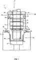
Die
Beispielsgemäß ist Grundkörper 3 mittels einem Gewinde in Anschlussöffnung 5 eingedreht. Dafür umfasst Grundkörper 3 an einem Verbindungsabschnitt 21 ein Außengewinde und Anschlussöffnung 5 ist entsprechend mit einem Innengewinde ausgestattet. Hierdurch ist Grundkörper 3 fest mit Anschlussöffnung 5 von Anschlusskörper 4 verbunden. Es sind auch andere kraft- und/oder formschlüssige Verbindungsarten von Grundkörper 3 mit Anschlusskörper 4 möglich. Beispielsweise kann Grundkörper 3 in Anschlussöffnung 5 von Anschlusskörper 4 eingepresst sein.For example,
Mittels Anschlussvorrichtung 1 soll der Endabschnitt von Fluidleitung 2 mit Anschlusskörper 4 fest verbunden werden, damit ein Druckmittel durch Fluidleitung 2 entweder zu oder aus Anschlusskörper 4 geleitet werden kann.By means of connecting
Zum Verbinden von Fluidleitung 2 mit Anschlusskörper 4 wird der Endabschnitt von Fluidleitung 2 durch eine Einstecköffnung 19 eines Verschlussmittels 8 entlang einer Längsachse L von Anschlussvorrichtung 1 in Durchgangsöffnung 16 von Grundkörper 3 gesteckt. Im Grundkörper 3 ist ein Befestigungsmittel 7 angeordnet, welches dazu eingerichtet ist, den Endabschnitt von Fluidleitung 2 aufzunehmen und in Anschlussvorrichtung 1 zu halten. Befestigungsmittel 7 kann beispielsweise eine Fächerscheibe oder eine Sicherungsscheibe sein. Befestigungsmittel 7 ist in Durchgangsöffnung 16 von Grundkörper 3 axial verschiebbar sowie drehbeweglich gelagert. Die lose Aufnahme von Befestigungsmittel 7 im Grundkörper 3 bewirkt eine freie Bewegung entlang der Längsachse L sowie eine freie Drehbewegung des aufgenommenen Endabschnitts von Fluidleitung 2 im Grundkörper 3 um diese Achse. Dadurch lässt sich die mit Anschlussvorrichtung 1 verbundene Fluidleitung 2 einfach montieren, sowie demontieren und kann in verschiedenen Haltepositionen gehalten sowie verschoben werden. Beim Durchstecken des Endabschnitts von Fluidleitung 2 in Befestigungsmittel 7 werden radial nach innen gerichtete Laschen des Befestigungsmittel 7 von dem Endabschnitt verbogen. Die Laschen verkrallen sich dabei an der Außenwandung von Fluidleitung 2 wirken mit einer gewissen Gegenkraft als Widerhaken auf Fluidleitung 2 ein. Dadurch ist der Endabschnitt von Fluidleitung 2 im Grundkörper 3 gehalten und gegen ein Herausziehen oder Herausdrücken gesichert. Befestigungsmittel 7 liegt mit seinem äußerem Ring auf einer Anlageschulter 20 des Grundkörpers 3 auf. Anlageschulter 20 ist in Durchgangsöffnung 16 von Grundkörper 3 ausgebildet und ragt nach radial innen. Ab hier verjüngt sich zudem der Durchmesser von Durchgangsöffnung 16 in Richtung Anschlussöffnung 5.To connect
Damit der Endabschnitt von Fluidleitung 2 beim Einführen nicht zu tief in Anschlusskörper 4 geschoben wird, ist zudem ein ringförmiger Endanschlag 17 in im Grundkörper 3 ausgebildet. Endanschlag 17 ist am unteren Rand von Verbindungsabschnitt 21 von Grundkörper 3 als ein nach radial innen gerichteter Kragen geformt. Hier stößt das Ende von Fluidleitung 2 an und kann nicht weiter. Zugleich bildet Endanschlag 17 die Auslassöffnung von Anschlussvorrichtung 1.In order to ensure that the end section of
Auf den freiliegenden Abschnitt von Grundkörper 3, welcher als Verschlussabschnitt 22 dient, ist Verschlussmittel 8 in Montagerichtung Y auf Grundkörper 3 gesetzt. Verschlussmittel 8 umfasst ein Sicherungsmittel 13 mittels welchen Verschlussmittel 8 fest, aber lösbar mit Grundkörper 3 verbunden ist. Auf die zerstörungsfreie Befestigung von Verschlussmittel 8 mit Grundkörper 3 und die verschiedenen Verbindungsarten wird in der Beschreibung zu den
Im inneren von Durchgangsöffnung 16 sind neben Befestigungsmittel 7 noch weitere Mittel angeordnet, welche zur Befestigung und Abdichtung von Fluidleitung 2 in Anschlussvorrichtung 1 beitragen. Entgegen der Montagerichtung Y gesehen folgt auf Befestigungsmittel 7 ein erstes Distanzmittel 9, welches auf Befestigungsmittel 7 aufliegt. Darauf folgt mit leicht räumlichen Abstand ein erstes Dichtmittel 10. Davon leicht räumlich beabstandet ein zweites Distanzmittel 11 und davon ebenfalls leicht räumlich beabstandet ein zweites Dichtmittel 12. Abgeschlossen wird diese Anordnung von Verschlussmittel 8, welches die Mittel 7, 9, 10, 11 und 12 in Durchgangsöffnung 16 von Grundkörper 3 hält. Demzufolge sind erstes Distanzmittel 9, erstes Dichtmittel 10, zweites Distanzmittel 11 und zweites Dichtmittel 12 über den Endabschnitt von Fluidleitung 2 gesteckt.In addition to fastening means 7, further means are arranged inside the through-opening 16, which contribute to fastening and sealing the
Befestigungsmittel 7 ist dazu eingerichtet auf Fluidleitung 2 wirkende Zug- und/oder Druckkräfte über erstes Distanzmittel 9 auf erstes Dichtmittel 10 und weiter über zweites Distanzmittel 11 und zweites Dichtmittel 12 auf Verschlussmittel 8 zu übertragen. Befestigungsmittel 7, erstes Distanzmittel 9, erstes Dichtmittel 10, zweites Distanzmittel 11 und zweites Dichtmittel 12 sind innerhalb von Durchgangsöffnung 16 des Grundkörpers 3 in Längsrichtung beweglich gelagert, damit bei wirkenden Zug- und/oder Druckkräften auf Fluidleitung 2 eine erhöhte Kompression der Dichtmittel 10 und 12 erreicht wird und somit eine größere Abdichtwirkung gegen innere und äußere Einflüsse erzeugt ist.Fastening means 7 is designed to transfer tensile and/or compressive forces acting on
Dabei hat das zweite Distanzmittel 11 den Vorteil, dass das erste Dichtmittel 10 einen ordnungsgemäßen Sitz hat sowie seine ordnungsgemäße Funktion in Grundkörper 3 erfüllt. Sinn und Zweck des zweiten Distanzmittels 11 ist, dass Befestigungsmittel 7, erstes Distanzmittel 9 und erstes Dichtmittel 10 nach der Montage in Durchgangsöffnung 16 plan zueinander ausgerichtet sind, bevor Verschlussmittel 8 auf Grundkörper 3 montiert wird. Zweites Distanzmittel 11 hat noch zudem den Vorteil, dass Fluidleitung 2 bei der Montage und Demontage in Durchgangsöffnung 16 von Grundkörper 3 einfacher geführt und somit besser ausgerichtet ist. Dadurch wird Befestigungsmittel 7 senkrecht in Durchgangsöffnung 16 geschoben, sodass es nicht verkeilen kann und es zu keiner Beschädigung kommt.The
Weiterhin ist vorteilhaft, dass durch zweites Distanzmittel 11 die Fluidleitung 2 mit zweitem Dichtmittel 12 bei der Demontage aus einer defekten Anschlussvorrichtung 1 entnommen werden kann und bei anschließender Montage in eine neue Anschlussvorrichtung 1 besser eingeführt und gegenüber einer Beschädigung geschützt ist.Furthermore, it is advantageous that the
Zweites Dichtmittel 12 dichtet Fluidleitung 2 im Bereich von Einstecköffnung 19 des Verschlussmittels 8 ab. Dadurch kann auf ein Dichtmittel einem Verschlussmittel verzichtet werden. Zweites Dichtmittel 12 dient zum Schutz gegen Umwelteinflüsse wie beispielsweise Wasser, Schmutz oder sonstige Medien. Anschlussvorrichtung 1 ist somit gegenüber Einflüssen von außen abgedichtet, welche auf die darin aufgenommene Fluidleitung 2 einwirken könnten.Second sealing means 12 seals
Insbesondere beim Einsatz von Anschlussvorrichtung 1 in einem Fahrzeug ist Fluidleitung 2 Zug- und/oder Druckkräften ausgesetzt. Durch elastische Dichtmittel 10 und 12 wird bei eine Kompression erreicht, welche besonders gut Fluidleitung 2 luftdicht abdichtet und nach Außen gegen Umwelteinflüsse schützt.In particular, when using the
Verschlussmittel 8 mit seiner gegenüber dem Durchmesser von Durchgangsöffnung 16 kleiner Einstecköffnung 19 ist dazu eingerichtet auf Fluidleitung 2 wirkende Zug- und/oder Druckkräfte aufzunehmen, welcher über Befestigungsmittel 7, erstes Distanzmittel 9, erstes Dichtmittel 10, zweites Distanzmittel 11 und zweites Dichtmittel 12 auf dieses übertragen werden.Closure means 8 with its
Grundkörper 3 ist beispielsgemäß aus einem korrosionsbeständigen Kunststoffmaterial hergestellt, damit eine Korrosion zwischen Anschlusskörper 4 und Grundkörper 3 verhindert wird. Als Kunststoff werden beispielsweise Polyolefine, Polyvinylchloride oder Fluorpolymere verwendet. Diese Kunststoffmaterialien sind gegenüber beispielsweise Messing kostengünstiger sowie einfacher in der Erzeugung und Bearbeitung einer Anschlussvorrichtung 1. Zudem weisen diese Kunststoffmaterialien eine galvanische Korrosionsbeständigkeit von Anschlussvorrichtung 1 gegenüber Anschlusskörper 4 bei beispielsweise einwirkenden Umgebungseinflüssen wie Salz und Wasser auf.For example,
Grundkörper 3 umfasst weiterhin an seinem äußeren Umfang am Übergang von Verbindungsabschnitt 21 in Richtung von Verschlussabschnitt 22 einen Flansch 15 mit einer umfänglich verlaufenden Nut 14, in welcher ein Grundkörperdichtmittel 6 eingesetzt ist, wodurch Grundkörper 3 gegenüber Anschlusskörper 4 abgedichtet ist. Dadurch wird ein Austreten von Fluid aus Anschlusskörper 4 entlang der Verbindung mit Grundkörper 3 verhindert.The
In den nachfolgenden
Die
Die
In der
Abschließen wird in der
Vorteil der zerstörungsfreien Demontage von Verschlussmittel 8 gemäß den
Ein weiterer Vorteil besteht darin, dass nach dem Herausziehen der Fluidleitung das Befestigungsmittel durch Zerstören entfernt wird. Somit können die auf die Fluidleitung geschobenen Dichtmitteln und die Distanzmitteln abgezogen und wiederverwendet werden. Dies hat zum Vorteil, dass bei einem Austausch einer defekten Anschlussvorrichtung die Fluidleitung nicht abgeschnitten werden muss und somit zum Anschluss an eine neue Anschlussvorrichtung verwendet werden kann.Another advantage is that after the fluid line is pulled out, the fastening means is removed by destroying it. This means that the sealing means and spacers pushed onto the fluid line can be removed and reused. This has the advantage that when replacing a defective connection device, the fluid line does not have to be cut off and can therefore be used to connect to a new connection device.
Bezugszeichenlistelist of reference symbols
- 11
- Anschlussvorrichtungconnection device
- 22
- Fluidleitungfluid line
- 33
- Grundkörperbase body
- 44
- Anschlusskörperconnector body
- 55
- Anschlussöffnungconnection opening
- 66
- Grundkörperdichtmittelbase body sealant
- 77
- Befestigungsmittelfasteners
- 88
- Verschlussmittelclosure means
- 99
- erstes Distanzmittelfirst distance device
- 1010
- erstes Dichtmittelfirst sealant
- 1111
- zweites Distanzmittelsecond distance means
- 1212
- zweites Dichtmittelsecond sealant
- 1313
- Sicherungsmittelsecuring means
- 1414
- NutNut
- 1515
- Flanschflange
- 1616
- Durchgangsöffnungpassage opening
- 1717
- Endanschlagend stop
- 1818
- Gewindethread
- 1919
- Einstecköffnunginsertion opening
- 2020
- Anlageschulterinvestment shoulder
- 2121
- Verbindungsabschnittconnecting section
- 2222
- Verschlussabschnittclosure section
- LL
- Längsachselongitudinal axis
- YY
- Montagerichtungmounting direction
ZITATE ENTHALTEN IN DER BESCHREIBUNGQUOTES INCLUDED IN THE DESCRIPTION
Diese Liste der vom Anmelder aufgeführten Dokumente wurde automatisiert erzeugt und ist ausschließlich zur besseren Information des Lesers aufgenommen. Die Liste ist nicht Bestandteil der deutschen Patent- bzw. Gebrauchsmusteranmeldung. Das DPMA übernimmt keinerlei Haftung für etwaige Fehler oder Auslassungen.This list of documents listed by the applicant was generated automatically and is included solely for the better information of the reader. The list is not part of the German patent or utility model application. The DPMA accepts no liability for any errors or omissions.
Zitierte PatentliteraturCited patent literature
- WO 2017/129667 A1 [0003]WO 2017/129667 A1 [0003]
Claims (12)
Translated fromGermanPriority Applications (4)
| Application Number | Priority Date | Filing Date | Title |
|---|---|---|---|
| DE102023206627.0ADE102023206627A1 (en) | 2023-07-12 | 2023-07-12 | Connection device for connecting a fluid line to a connection body |
| CN202410836360.9ACN119309075A (en) | 2023-07-12 | 2024-06-26 | Connecting device for connecting a fluid line to a connecting body |
| JP2024103736AJP2025013215A (en) | 2023-07-12 | 2024-06-27 | CONNECTION DEVICE FOR CONNECTING A FLUID LINE TO A CONNECTION BODY - Patent application |
| US18/770,983US20250020250A1 (en) | 2023-07-12 | 2024-07-12 | Connection device for connecting a fluid line to a connection body |
Applications Claiming Priority (1)
| Application Number | Priority Date | Filing Date | Title |
|---|---|---|---|
| DE102023206627.0ADE102023206627A1 (en) | 2023-07-12 | 2023-07-12 | Connection device for connecting a fluid line to a connection body |
Publications (1)
| Publication Number | Publication Date |
|---|---|
| DE102023206627A1true DE102023206627A1 (en) | 2025-01-16 |
Family
ID=93930408
Family Applications (1)
| Application Number | Title | Priority Date | Filing Date |
|---|---|---|---|
| DE102023206627.0APendingDE102023206627A1 (en) | 2023-07-12 | 2023-07-12 | Connection device for connecting a fluid line to a connection body |
Country Status (4)
| Country | Link |
|---|---|
| US (1) | US20250020250A1 (en) |
| JP (1) | JP2025013215A (en) |
| CN (1) | CN119309075A (en) |
| DE (1) | DE102023206627A1 (en) |
Citations (5)
| Publication number | Priority date | Publication date | Assignee | Title |
|---|---|---|---|---|
| DE3923579A1 (en)* | 1988-07-21 | 1990-01-25 | Schaefer Stettiner Schrauben | Connector for plastics pipes - is in one piece with widening bore socket for holding ring and sealing ring |
| EP0610538A1 (en)* | 1993-02-12 | 1994-08-17 | Anton Hummel Verwaltungs GmbH | Quick connection for pipes, hoses and the like |
| US20070108764A1 (en)* | 2005-11-04 | 2007-05-17 | Aldo Nicolino | Fast-fit coupling for a fluid circulation system |
| EP2366934A1 (en)* | 2010-03-03 | 2011-09-21 | R. Nussbaum AG | Coupling piece for metal pipes |
| WO2017129667A1 (en) | 2016-01-28 | 2017-08-03 | Voss Automotive Gmbh | Coupling body for a plug connection of pipelines, in particular plastic pipelines |
Family Cites Families (9)
| Publication number | Priority date | Publication date | Assignee | Title |
|---|---|---|---|---|
| US4664427A (en)* | 1985-04-01 | 1987-05-12 | Master Industries, Inc. | Quick connect fitting |
| JPH01255790A (en)* | 1988-04-06 | 1989-10-12 | Toosetsu Kk | Joining construction for new charge and exhaust cylinder |
| US5609370A (en)* | 1994-12-02 | 1997-03-11 | Itt Corporation | Positive latch quick connector |
| US6733047B1 (en)* | 1999-09-22 | 2004-05-11 | Itt Manufacturing Enterprises, Inc. | Quick connector for fuel/vapor applications |
| US20160025252A1 (en)* | 2014-07-23 | 2016-01-28 | Paccar Inc | Quick fitting connector |
| JP6078857B2 (en)* | 2015-08-27 | 2017-02-15 | 株式会社トヨックス | Pipe fitting |
| JP7358165B2 (en)* | 2019-09-30 | 2023-10-10 | 積水化学工業株式会社 | Piping connection members, connection joints |
| CN111706735A (en)* | 2020-07-16 | 2020-09-25 | 日丰企业(佛山)有限公司 | a pipe joint |
| JP7057855B2 (en)* | 2020-08-04 | 2022-04-20 | Njt銅管株式会社 | Pressure-resistant pipe fittings and pipe connection methods using them |
- 2023
- 2023-07-12DEDE102023206627.0Apatent/DE102023206627A1/enactivePending
- 2024
- 2024-06-26CNCN202410836360.9Apatent/CN119309075A/enactivePending
- 2024-06-27JPJP2024103736Apatent/JP2025013215A/enactivePending
- 2024-07-12USUS18/770,983patent/US20250020250A1/enactivePending
Patent Citations (5)
| Publication number | Priority date | Publication date | Assignee | Title |
|---|---|---|---|---|
| DE3923579A1 (en)* | 1988-07-21 | 1990-01-25 | Schaefer Stettiner Schrauben | Connector for plastics pipes - is in one piece with widening bore socket for holding ring and sealing ring |
| EP0610538A1 (en)* | 1993-02-12 | 1994-08-17 | Anton Hummel Verwaltungs GmbH | Quick connection for pipes, hoses and the like |
| US20070108764A1 (en)* | 2005-11-04 | 2007-05-17 | Aldo Nicolino | Fast-fit coupling for a fluid circulation system |
| EP2366934A1 (en)* | 2010-03-03 | 2011-09-21 | R. Nussbaum AG | Coupling piece for metal pipes |
| WO2017129667A1 (en) | 2016-01-28 | 2017-08-03 | Voss Automotive Gmbh | Coupling body for a plug connection of pipelines, in particular plastic pipelines |
Also Published As
| Publication number | Publication date |
|---|---|
| US20250020250A1 (en) | 2025-01-16 |
| JP2025013215A (en) | 2025-01-24 |
| CN119309075A (en) | 2025-01-14 |
Similar Documents
| Publication | Publication Date | Title |
|---|---|---|
| DE102007008066B4 (en) | fitting | |
| DE112008004188B4 (en) | Fixing structure with a grommet | |
| DE102007047860B3 (en) | Connecting element, e.g. for automobile, has bolt, non-removable sleeve with first narrow point, second narrow point with radially sprung element(s) that engage thread in force- and/or shape-locking manner and axially continuous slot or gap | |
| EP2136088A2 (en) | Connection element with a screw and an undetachable attached casing | |
| DE102010061067A1 (en) | Device for fixing a cable to a cable outlet connection | |
| EP2413012B1 (en) | Connector | |
| WO2012136784A2 (en) | Line connector having a connection barb for a plastic pipeline | |
| DE202007012400U1 (en) | Connecting device for media lines in the region of a wall duct and wall element | |
| WO2016155861A1 (en) | Plug-in connection arrangement and method for preparing a plug-in connection arrangement | |
| EP1540234B1 (en) | Adapter-intermediate ring for a screw-in part of a fluid plug system | |
| DE102016124805B4 (en) | membrane valve | |
| WO2009007165A1 (en) | Charge-air hose | |
| DE102013223241B4 (en) | Heat transfer medium connection assembly, in particular for a heat exchanger arrangement of a vehicle heater | |
| DE102011053447A1 (en) | Cable fitting for fixation of cable at plug connector housing or housing wall of switching cabinet, has sealing element and strain relief element arranged in series in axial direction, and flange plates arranged parallel to each other | |
| DE102009033948A1 (en) | Cable or hose coupling device comprises hollow cylindric connecting piece connected with housing, and pressure element with clamping section, where attachment section is provided for attachment of coupling in opening of wall of housing | |
| EP0898109A1 (en) | Plug coupling for pipes | |
| DE60026946T2 (en) | Means for pressing a shaft to a clevis of a steering device | |
| DE102023206627A1 (en) | Connection device for connecting a fluid line to a connection body | |
| EP1936252B1 (en) | Connector device for media lines | |
| EP2095003B1 (en) | Block connector for fluid conduits | |
| EP4127494B1 (en) | Retaining nut | |
| DE19819758A1 (en) | Plug connection for pipes | |
| DE10007527C2 (en) | Sealing packing for leading cables through a wall | |
| DE102018107505A1 (en) | "Connecting device for media lines" | |
| DE102022107490A1 (en) | Modular connector |
Legal Events
| Date | Code | Title | Description |
|---|---|---|---|
| R012 | Request for examination validly filed | ||
| R081 | Change of applicant/patentee | Owner name:CONTINENTAL AUTOMOTIVE TECHNOLOGIES GMBH, DE Free format text:FORMER OWNER: CONTINENTAL AUTOMOTIVE TECHNOLOGIES GMBH, 30165 HANNOVER, DE | |
| R016 | Response to examination communication |