DE102023127790A1 - Robot arm control with haptic feedback to an operator during control - Google Patents
Robot arm control with haptic feedback to an operator during controlDownload PDFInfo
- Publication number
- DE102023127790A1 DE102023127790A1DE102023127790.1ADE102023127790ADE102023127790A1DE 102023127790 A1DE102023127790 A1DE 102023127790A1DE 102023127790 ADE102023127790 ADE 102023127790ADE 102023127790 A1DE102023127790 A1DE 102023127790A1
- Authority
- DE
- Germany
- Prior art keywords
- manipulator arm
- handle
- robot
- workpiece
- holding device
- Prior art date
- Legal status (The legal status is an assumption and is not a legal conclusion. Google has not performed a legal analysis and makes no representation as to the accuracy of the status listed.)
- Pending
Links
Images

Classifications
- B—PERFORMING OPERATIONS; TRANSPORTING
- B25—HAND TOOLS; PORTABLE POWER-DRIVEN TOOLS; MANIPULATORS
- B25J—MANIPULATORS; CHAMBERS PROVIDED WITH MANIPULATION DEVICES
- B25J9/00—Programme-controlled manipulators
- B25J9/16—Programme controls
- B25J9/1628—Programme controls characterised by the control loop
- B25J9/1633—Programme controls characterised by the control loop compliant, force, torque control, e.g. combined with position control
- B—PERFORMING OPERATIONS; TRANSPORTING
- B25—HAND TOOLS; PORTABLE POWER-DRIVEN TOOLS; MANIPULATORS
- B25J—MANIPULATORS; CHAMBERS PROVIDED WITH MANIPULATION DEVICES
- B25J13/00—Controls for manipulators
- B25J13/08—Controls for manipulators by means of sensing devices, e.g. viewing or touching devices
- B25J13/085—Force or torque sensors
- B—PERFORMING OPERATIONS; TRANSPORTING
- B25—HAND TOOLS; PORTABLE POWER-DRIVEN TOOLS; MANIPULATORS
- B25J—MANIPULATORS; CHAMBERS PROVIDED WITH MANIPULATION DEVICES
- B25J9/00—Programme-controlled manipulators
- B25J9/16—Programme controls
- B25J9/1656—Programme controls characterised by programming, planning systems for manipulators
- B25J9/1664—Programme controls characterised by programming, planning systems for manipulators characterised by motion, path, trajectory planning
- B—PERFORMING OPERATIONS; TRANSPORTING
- B25—HAND TOOLS; PORTABLE POWER-DRIVEN TOOLS; MANIPULATORS
- B25J—MANIPULATORS; CHAMBERS PROVIDED WITH MANIPULATION DEVICES
- B25J9/00—Programme-controlled manipulators
- B25J9/16—Programme controls
- B25J9/1656—Programme controls characterised by programming, planning systems for manipulators
- B25J9/1669—Programme controls characterised by programming, planning systems for manipulators characterised by special application, e.g. multi-arm co-operation, assembly, grasping
- G—PHYSICS
- G05—CONTROLLING; REGULATING
- G05B—CONTROL OR REGULATING SYSTEMS IN GENERAL; FUNCTIONAL ELEMENTS OF SUCH SYSTEMS; MONITORING OR TESTING ARRANGEMENTS FOR SUCH SYSTEMS OR ELEMENTS
- G05B19/00—Programme-control systems
- G05B19/02—Programme-control systems electric
- G05B19/42—Recording and playback systems, i.e. in which the programme is recorded from a cycle of operations, e.g. the cycle of operations being manually controlled, after which this record is played back on the same machine
- G05B19/423—Teaching successive positions by walk-through, i.e. the tool head or end effector being grasped and guided directly, with or without servo-assistance, to follow a path
- G—PHYSICS
- G05—CONTROLLING; REGULATING
- G05B—CONTROL OR REGULATING SYSTEMS IN GENERAL; FUNCTIONAL ELEMENTS OF SUCH SYSTEMS; MONITORING OR TESTING ARRANGEMENTS FOR SUCH SYSTEMS OR ELEMENTS
- G05B2219/00—Program-control systems
- G05B2219/30—Nc systems
- G05B2219/36—Nc in input of data, input key till input tape
- G05B2219/36429—Power assisted positioning
- G—PHYSICS
- G05—CONTROLLING; REGULATING
- G05B—CONTROL OR REGULATING SYSTEMS IN GENERAL; FUNCTIONAL ELEMENTS OF SUCH SYSTEMS; MONITORING OR TESTING ARRANGEMENTS FOR SUCH SYSTEMS OR ELEMENTS
- G05B2219/00—Program-control systems
- G05B2219/30—Nc systems
- G05B2219/39—Robotics, robotics to robotics hand
- G05B2219/39124—Grasp common rigid object, no movement end effectors relative to object
Landscapes
- Engineering & Computer Science (AREA)
- Robotics (AREA)
- Mechanical Engineering (AREA)
- Physics & Mathematics (AREA)
- General Physics & Mathematics (AREA)
- Automation & Control Theory (AREA)
- Human Computer Interaction (AREA)
- Manipulator (AREA)
Abstract
Translated fromGerman
Description
Translated fromGermanDie vorliegende Erfindung betrifft eine Roboterarmsteuerung mit haptischer Rückmeldung an einen Bediener bei Steuerung.The present invention relates to a robot arm controller with haptic feedback to an operator during control.
Bekannt sind Manipulatorarme, insbesondere bei Industrierobotern, mit zugehöriger Robotersteuerung. Industrieroboter können an ihren Manipulatorarmen beispielsweise mit Werkzeugen ausgerüstet sein und dieses Werkzeug halten. Unter anderem typische Werkzeuge sind dabei Werkzeuge zur Bearbeitung von Metall wie beispielsweise Schweiß- oder Fräs- oder Schleifköpfe.Manipulator arms, especially in industrial robots, with associated robot controllers are well known. Industrial robots can, for example, be equipped with tools on their manipulator arms and hold these tools. Typical tools include tools for processing metal, such as welding, milling, or grinding heads.
Manipulatorarme weisen dabei gewöhnlicherweise mehrere Gliedelemente auf, die über elektrisch angetriebene Gelenke ein gehaltenes Werkzeug hinsichtlich Orientierung und Position positionieren und ansteuern können.Manipulator arms usually have several link elements that can position and control a held tool in terms of orientation and position via electrically driven joints.
In der Automobilindustrie werden solche Roboter beispielsweise für automatisierte Schweißarbeiten eingesetzt, wobei die Roboter dabei Schritte eines gespeicherten Programms ausführen.In the automotive industry, for example, such robots are used for automated welding work, with the robots carrying out steps of a stored program.
Bekannt ist auch, Industrieroboter auf Linearachsen mittels einer speicherprogrammierbaren Steuerung oder als sogenannte externe Achse in der Robotersteuerung integriert entlang einer Linearachse zu verfahren.It is also known to move industrial robots on linear axes using a programmable logic controller or as a so-called external axis integrated in the robot controller along a linear axis.
Es ist auch bekannt derartige Industrieroboter in Kollaboration mit einem Bedienenden als sogenannte Cobots (collaborating robot) zu betreiben. Diese Cobots unterscheiden sich von einem herkömmlichen Industrieroboter dadurch, dass sie für die direkte Interaktion von Mensch und Maschine geeignet sind. Diese Roboter können sowohl automatisierte Verfahrensschritte nach einem vorgegebenen Programm durchführen als auch direkt Verfahrensschritte durchführen, während der Roboter durch einen Bediener geführt wird. Im zweiten Fall wird der Roboter als Unterstützung für den Bediener verwendet. Der Roboter kann dann ein Werkzeug zu einem Werkstück positionieren und orientieren, wobei der Bediener den Roboter führt und ansteuert.It is also known to operate such industrial robots in collaboration with an operator as so-called cobots (collaborating robots). These cobots differ from conventional industrial robots in that they are suitable for direct human-machine interaction. These robots can both perform automated process steps according to a predefined program and perform process steps directly while the robot is guided by an operator. In the latter case, the robot is used to support the operator. The robot can then position and orient a tool relative to a workpiece, with the operator guiding and controlling the robot.
Der vorliegenden Erfindung liegt die Aufgabe zugrunde, für den Bediener die Steuerung des Roboters intuitiv und einfach zu gestalten.The object of the present invention is to make the control of the robot intuitive and simple for the operator.
Diese Aufgabe wird gelöst mit den Merkmalen der unabhängigen Ansprüche. Weitere vorteilhafte Ausgestaltungen der Erfindung sind in den abhängig formulierten Ansprüchen angegeben. Die in den abhängig formulierten Ansprüchen einzeln aufgeführten Merkmale sind in technologisch sinnvollerweise miteinander kombinierbar und können weitere Ausgestaltungen der Erfindung definieren.This object is achieved by the features of the independent claims. Further advantageous embodiments of the invention are specified in the dependent claims. The features listed individually in the dependent claims can be combined with one another in a technologically expedient manner and can define further embodiments of the invention.
Es wird ein Roboter zum Halten und Bearbeiten eines Werkstücks vorgestellt, der eine Steuerung zum Ansteuern einer Halteeinrichtung und zum Ansteuern eines Manipulatorarms sowie einen entsprechenden mehrgliedrigen Manipulatorarm umfasst. Der Manipulatorarm weist ein Griffstück auf, wobei der Manipulatorarm dazu eingerichtet ist Kräfte zu ermitteln, die durch den Bediener auf das Griffstück des Manipulatorarms ausgeübt werden, und entsprechende Informationen an die Steuerung zu übertragen. Weiterhin umfasst der Roboter eine Halteeinrichtung zum Halten des Werkstücks oder eines Werkzeugs. In einer Ausführungsform kann die Halteeinrichtung an dem distalen Ende des Manipulatorarms angeordnet sein. In einer anderen Ausführungsform kann die Halteeinrichtung an dem proximalen Ende des Manipulatorarms angeordnet sein. Die Halteeinrichtung ist informativ mit der Steuerung verbunden und ist dazu eingerichtet, das Werkstück beispielsweise linear oder rotatorisch zu verfahren. Die Steuerung ist dazu eingerichtet die Halteeinrichtung und/oder den Manipulatorarm anzusteuern, die Position des Werkstücks relativ zu dem Manipulatorarm entsprechend der über den Manipulatorarm ermittelten Kräfte linear oder rotatorisch zu verfahren. Die Steuerung ist dazu eingerichtet, gleichzeitig mit der Ansteuerung der Halteeinrichtung das Griffstück des Manipulatorarms basierend auf den über den Manipulatorarm ermittelten Kräfte linear oder rotatorisch aus einer Ausgangsposition auszulenken. Der Ausdruck „gleichzeitig“ beschreibt dabei, dass das Aufbringen einer Kraft und das dadurch bewirkte Auslenken des Manipulatorarms in der Wahrnehmung des Bedieners gleichzeitig ist, also das Auslenken zeitlich nicht merklich zum Aufbringen der Kraft unterscheidbar ist. Denn typischerweise ist die Zeit zum Übertragen von Signalen, Verarbeiten von Signalen vernachlässigbar oder subjektiv von einem Bediener nicht wahrnehmbar. Das Auslenken des Manipulatorarms aus einer vorherigen Referenz- oder Ausgangsposition endet, sobald ermittelt ist, dass keine Kraft mehr auf das Griffstück ausgeübt wird. Entsprechend ist der Manipulatorarm dann wieder in eine vorherige Ausgangs- oder Referenzposition zurückgeführt.A robot for holding and processing a workpiece is presented, comprising a controller for controlling a holding device and for controlling a manipulator arm, as well as a corresponding multi-joint manipulator arm. The manipulator arm has a handle, wherein the manipulator arm is configured to determine forces exerted by the operator on the handle of the manipulator arm and to transmit corresponding information to the controller. Furthermore, the robot comprises a holding device for holding the workpiece or a tool. In one embodiment, the holding device can be arranged at the distal end of the manipulator arm. In another embodiment, the holding device can be arranged at the proximal end of the manipulator arm. The holding device is informationally connected to the controller and is configured to move the workpiece, for example, linearly or rotationally. The controller is configured to control the holding device and/or the manipulator arm to move the position of the workpiece relative to the manipulator arm linearly or rotationally according to the forces determined via the manipulator arm. The controller is designed to simultaneously control the holding device and linearly or rotationally deflect the handle of the manipulator arm from a starting position based on the forces determined via the manipulator arm. The term "simultaneous" describes that the application of a force and the resulting deflection of the manipulator arm are simultaneous in the perception of the operator, i.e. the deflection cannot be noticeably distinguished from the application of the force. This is because the time required to transmit and process signals is typically negligible or subjectively imperceptible to an operator. The deflection of the manipulator arm from a previous reference or starting position ends as soon as it is determined that no further force is being exerted on the handle. The manipulator arm is then returned to a previous starting or reference position.
Der Manipulatorarm weist ein distales Ende und ein proximales Ende auf, wobei das proximale Ende mit dem Fundament oder dem Werktisch oder einer anderen geeigneten Halterung verbunden ist. Weiterhin kann der Manipulatorarm mehrere Gliedelemente umfassen, die über Gelenke und Achsen miteinander bewegbar verbunden sind. Dazu kann der Manipulatorarm Motoren, Getriebe und Winkelgeber aufweisen, welche den Manipulatorarm bewegen. Der Manipulatorarm kann weiterhin Leitungen zur Energieversorgung, Ansteuerung und Signalübertragen aufweisen.The manipulator arm has a distal end and a proximal end, with the proximal end being connected to the base or workbench or another suitable support. Furthermore, the manipulator arm can comprise several link elements that are movably connected to one another via joints and axes. For this purpose, the manipulator arm can have motors, gears, and angle encoders that move the manipulator arm. The manipulator arm can also have lines for power supply, control, and signal transmission.
Der Manipulatorarm weist insbesondere mindestens zwei Gliedelemente auf. Die Gliedelemente sind sequenziell miteinander über Gelenke verbunden. Die Gelenke können durch elektrische Motoren angetrieben werden, wobei ein Gelenk in mehrere Freiheitsgraden bewegt werden kann. Insbesondere kann das Gelenk einen rotatorischen Freiheitsgrad aufweisen. Besonders bevorzugt weist ein Gelenk zwei rotatorische Freiheitsgrade auf. Ein Roboter mit einem mehrgliedrigen Manipulatorarm hat den technischen Vorteil dass aufwendigere Bewegungen möglich sind und der Manipulatorarm sein distales Ende auch an Stellen des Werkstücks positionieren und orientieren kann, die sonst nur schwer oder gar nicht zu erreichen sind.The manipulator arm, in particular, has at least two link elements. The link elements are sequentially connected to one another via joints. The joints can be driven by electric motors, with each joint being capable of movement in multiple degrees of freedom. In particular, the joint can have one rotational degree of freedom. Particularly preferably, each joint has two rotational degrees of freedom. A robot with a multi-link manipulator arm has the technical advantage that more complex movements are possible, and the manipulator arm can position and orient its distal end even at points on the workpiece that would otherwise be difficult or impossible to reach.
Das Werkstück kann aus einem beliebigen Material sein. Es kann beispielsweise metallisch oder mineralisch sein, bevorzugt kann das Werkstück ein Kunststoff sein, und besonders bevorzugt kann das Werkstück eine Mischung verschiedener Materialien sein.The workpiece can be made of any material. For example, it can be metallic or mineral; preferably, the workpiece can be a plastic, and particularly preferably, the workpiece can be a mixture of different materials.
Bearbeiten bedeutet, dass ein Werkzeug zum Werkstück geführt wird und das Werkstück mit dem Werkzeug bearbeitet wird. Bearbeiten kann auch bedeuten, dass ein Werkstück zum Werkzeug geführt wird und das Werkstück mit dem Werkzeug bearbeitet wird. Insbesondere kann an dem Werkstück etwas befestigt werden und/oder entfernt werden. Hierfür können bekannte Fertigungsverfahren verwendet werden. Bearbeiten kann auch bedeuten, dass das Werkstück positioniert wird oder vermessen wird.Machining means that a tool is brought to the workpiece and the workpiece is machined with the tool. Machining can also mean that a workpiece is brought to the tool and the workpiece is machined with the tool. In particular, something can be attached to and/or removed from the workpiece. Known manufacturing processes can be used for this. Machining can also mean that the workpiece is positioned or measured.
Der Manipulatorarm weist ein Griffstück auf, welches typischerweise so an seinem distalen Ende angeordnet ist, dass es nah an dem Werkzeug angeordnet ist, welches am Ende des Manipulatorarms angeordnet werden kann. Ein Bediener kann den Manipulatorarm mittels des Griffstücks steuern. Hierfür kann der Bediener das Griffstück umgreifen und eine Kraft auf das Griffstück ausüben, beispielsweise in eine Richtung.The manipulator arm has a handle, which is typically positioned at its distal end so that it is close to the tool, which can be positioned at the end of the manipulator arm. An operator can control the manipulator arm using the handle. To do so, the operator can grasp the handle and exert a force on the handle, for example, in one direction.
Das Griffstück kann auch ein jeglicher Bereich des Manipulatorarms sein, welcher dazu geeignet und vorgesehen ist, dass ein Bediener dieses ergreift, um eine Kraft auf den Manipulatorarm auszuüben, der nicht notwendigerweise ergonomisch ausgeformt ist. Bevorzugt ist das Griffstück oder der Griffbereich ein Bereich am distalen Ende des Manipulatorarms. In einer alternativen Ausführungsform ist das Griffstück ein Bereich des Werkzeugs.The handle can also be any area of the manipulator arm that is suitable and intended for an operator to grasp in order to exert a force on the manipulator arm, which is not necessarily ergonomically shaped. Preferably, the handle or grip area is an area at the distal end of the manipulator arm. In an alternative embodiment, the handle is an area of the tool.
Der Manipulatorarm ist dazu eingerichtet auf das Griffstück des Manipulatorarms ausgeübte Kräfte zu ermitteln und entsprechende Informationen an die Steuerung zu übertragen. Eine Kraft kann dabei auch ein Drehmoment um eine Rotationsachse sein. Der Manipulatorarm hält zunächst seine Pose und/oder die Position. Eine Pose des Manipulatorarms meint dabei, dass sich die mehreren Gliedelemente des Manipulatorarms sich zueinander nicht bewegen und dadurch die momentane Form des Manipulatorarms sich nicht ändert, abgesehen von einer Auslenkung des Griffstücks aus einer Ausgangsposition. Die Kraft des Bedieners am Griffstück wird dann auf den Manipulatorarm übertragen. Zur Messung der Kraft ist am/im Manipulatorarm ein dazu geeigneter Sensor, in einer Ausführungsform eine Kraftmesserdose, auch Kraftaufnehmer, oder Kraftsensor genannt, angebracht, welche die auf das Griffstück des Manipulatorarms ausgeübte Kräfte ermittelt und entsprechende Informationen an die Steuerung überträgt. In einer anderen Ausführungsform kann ein geeigneter Sensor die Kräfte an den Gelenken des Manipulatorarms messen.The manipulator arm is configured to detect forces exerted on the handle of the manipulator arm and transmit corresponding information to the controller. A force can also be a torque about a rotational axis. The manipulator arm initially maintains its pose and/or position. A pose of the manipulator arm means that the multiple link elements of the manipulator arm do not move relative to one another, and thus the current shape of the manipulator arm does not change, apart from a deflection of the handle from an initial position. The operator's force on the handle is then transmitted to the manipulator arm. To measure the force, a suitable sensor is attached to/in the manipulator arm. In one embodiment, this sensor is called a force transducer or force sensor. This sensor detects the forces exerted on the handle of the manipulator arm and transmits corresponding information to the controller. In another embodiment, a suitable sensor can measure the forces at the joints of the manipulator arm.
Eine Kraft am Griffstück kann vektoriell in verschiedene Orientierungen zerlegt werden. Dabei ist es vorteilhaft, die Kräfte drei zueinander orthogonalen Richtungen zuzuordnen. Insbesondere kann die Orientierung einer Kraft entlang einer linearen Bewegungsachse des Roboters zugeordnet werden.A force on the handle can be vectorially decomposed into different orientations. It is advantageous to assign the forces to three mutually orthogonal directions. In particular, the orientation of a force can be assigned along a linear motion axis of the robot.
Eine möglicherweise ungewünschte Bewegungsrichtung des Manipulatorarms kann sofort als Kraft am Griffstück registriert werden und entsprechend an die Steuerung übertragen werden. Ein Bediener kann, wie unten beschrieben, durch eine entsprechende Eingabe an die Steuerung vorgeben, dass nur vorgegebene Richtungen einer Kraft für die Ansteuerung der Halteeinrichtung oder des Manipulatorarms berücksichtigt werden sollen.A potentially undesired direction of movement of the manipulator arm can be immediately registered as a force on the handle and transmitted accordingly to the controller. As described below, an operator can specify, by sending a corresponding input to the controller, that only specified directions of a force should be considered for controlling the holding device or the manipulator arm.
Auf diese Weise können die Kräfte und Kräfteänderungen des Bedieners am Griffstück dediziert ermittelt werden, sodass beispielsweise eine Kraft in zwei Richtungen vektoriell zerlegt wird. Auf diese Weise kann beispielsweise eine Kraft in einer Richtung ignoriert werden, die zu einer Bewegung des Manipulatorarms oder des Werkstücks führen würde, die unerwünscht ist. Das kann die Sicherheit in der Interaktion zwischen Menschen und Maschine erhöhen.In this way, the operator's forces and force changes on the handle can be specifically determined, allowing, for example, a force to be vectorially decomposed into two directions. This allows, for example, a force in one direction that would lead to an undesirable movement of the manipulator arm or workpiece to be ignored. This can increase safety in human-machine interaction.
Eine ermittelte Kraft kann sowohl für die Ansteuerung der Halteeinrichtung verwendet werden, um diese in eine gewünschte Richtung zu bewegen oder zu rotieren, als auch für die Ansteuerung des Manipulatorarms verwendet werden, um diesen entsprechend der ermittelten Kraft aus einer Ausgangsposition zu bewegen und dem Bediener eine haptische Rückmeldung zu geben. Der Bediener kann damit nicht nur sehen, dass seine auf das Griffstück ausgeübte Kraft ein entsprechendes Verfahren des Werkstücks bewirkt, sondern erhält auch ein haptisches „Feedback“.A measured force can be used both to control the holding device to move or rotate it in a desired direction, and to control the manipulator arm to move it from an initial position according to the measured force, providing the operator with haptic feedback. This allows the operator not only to see that the force applied to the grip is causing the workpiece to move accordingly, but also to receive haptic feedback.
Die Steuerung ist dazu informativ mit der Halteeinrichtung verbunden, sodass die Steuerung Anweisungen zur Steuerung an die Halteeinrichtung übertragen kann. Die Halteeinrichtung ist dabei zum Halten des Werkstücks eingerichtet, wobei die Halteeinrichtung zum linearen oder rotatorischen Verfahren des Werkstücks eingerichtet ist. Der Bediener kann das Griffstück beispielsweise von sich wegdrücken oder zu sich hinziehen, um das Werkstück zu rotieren, wobei die Geschwindigkeit der Rotation mit zunehmender Druck- oder Zugkraft zunimmt und endet, sobald der Bediener keine Druck- oder Zugkraft mehr auf das Griffstück ausübt, und wobei gleichzeitig die Steuerung den Manipulatorarm in Abhängigkeit von der Größe der Druck- oder Zugkraft so ansteuert, dass das Griffstück in Abhängigkeit der Kraft aus der ursprüngliche Ausgangsposition auslenkt wird. Dementsprechend steuert die Steuerung den Manipulatorarm so an, dass das Griffstück bei abnehmender Kraft in die Ausgangsposition zurückkehrt.For this purpose, the controller is informatively connected to the holding device so that the controller can transmit control instructions to the holding device. The holding device is designed to hold the workpiece, wherein the holding device is designed for linear or rotational movement of the workpiece. The operator can, for example, push the handle away from themselves or pull it towards themselves to rotate the workpiece. The speed of rotation increases with increasing compressive or tensile force and ends as soon as the operator no longer exerts any compressive or tensile force on the handle. At the same time, the controller controls the manipulator arm depending on the magnitude of the compressive or tensile force so that the handle is deflected from its original starting position depending on the force. Accordingly, the controller controls the manipulator arm so that the handle returns to its starting position when the force decreases.
Die Halteeinrichtung kann dabei zumindest eine Rotationsachse aufweisen, um welche das Werkstück gedreht werden kann. Die Halteeinrichtung kann aber auch zumindest eine Linearachse aufweisen, entlang derer das Werkstück linear verfahren werden kann. Hierfür kann die Halteeinrichtung elektrische lineare und/oder rotatorische Antriebe aufweisen.The holding device can have at least one rotational axis around which the workpiece can be rotated. However, the holding device can also have at least one linear axis along which the workpiece can be moved linearly. For this purpose, the holding device can have electric linear and/or rotary drives.
Weiterhin kann der Bediener am Griffstück eine Kraft ausüben, um den Manipulatorarm in einer an sich starren Pose entlang einer Linearachse in die der Kraftrichtung entsprechenden Richtung zu verfahren. Eine starre Pose ist dabei eine solche, die lediglich ein Auslenken des Griffstücks ermöglicht, solange eine Kraft auf das Griffstück ausgeübt wird. Der Bediener kann damit beispielsweise das Griffstück zur Seite drücken und dadurch den Manipulatorarm in einer ansonsten starren Pose entlang einer Linearachse in die entsprechende Richtung verfahren, wobei das Griffstück während des Verfahrens ausgelenkt ist.Furthermore, the operator can exert a force on the handle to move the manipulator arm in an otherwise rigid pose along a linear axis in the direction corresponding to the force. A rigid pose is one that only allows the handle to be deflected as long as a force is applied to the handle. For example, the operator can push the handle to the side and thereby move the manipulator arm in an otherwise rigid pose along a linear axis in the corresponding direction, with the handle being deflected during the movement.
Die Ausgangsposition ist eine relative Position des Griffstücks bezogen auf eine starre Pose des Manipulatorarms. Die Ausgangs- oder Referenzposition kann auch als Ruhelage bezeichnet werden. In anderen Worten kann die Ausgangsposition auch vereinfacht mit Vektoren beschrieben werden. Von einem Koordinatenursprung ausgehend kann das proximale Ende des Manipulatorarms als ein Ortsvektor beschrieben werden. Dieser Ortsvektor kann verändert werden, indem beispielsweise der Manipulatorarm auf einer Linearachse verschoben wird. Ein Griffstückvektor bezeichnet einen Vektor von dem proximalen Ende des Manipulatorarms auf das Griffstück. Ist der Manipulatorarm in einer starren Pose, so ist der Griffstückvektor die Auslenkung.The starting position is a relative position of the handle in relation to a rigid pose of the manipulator arm. The starting or reference position can also be referred to as the rest position. In other words, the starting position can also be described simply using vectors. Starting from a coordinate origin, the proximal end of the manipulator arm can be described as a position vector. This position vector can be changed, for example, by moving the manipulator arm along a linear axis. A handle vector refers to a vector from the proximal end of the manipulator arm to the handle. If the manipulator arm is in a rigid pose, the handle vector is the deflection.
Das Griffstück des Manipulatorarms kann in der starren Pose des Manipulatorarms entlang einer erlaubten Auslenkungsstrecke ausgelenkt werden und/oder entlang eines erlaubten Drehwinkels verdreht werden. Die lineare oder rotatorische Verfahrbewegung der starren Pose des Manipulatorarms oder der Halteeinrichtung kann umso schneller ausgeführt werden, desto größer die auf das Griffstück ausgeübte Kraft ist. Da eine größere Kraft auf das Griffstück typischerweise eine entsprechend größere Auslenkung des Griffstücks bewirkt, wird auch das Griffstück entlang der erlaubten Auslenkungsstrecke aus der Ausgangsposition weiter ausgelenkt.The handle of the manipulator arm can be deflected along a permitted deflection distance and/or rotated along a permitted angle of rotation in the rigid pose of the manipulator arm or the holding device. The greater the force exerted on the handle, the faster the linear or rotational movement of the rigid pose of the manipulator arm or the holding device can be performed. Since a greater force on the handle typically causes a correspondingly greater deflection of the handle, the handle is also deflected further from the starting position along the permitted deflection distance.
Der Bediener des Roboters erhält damit gleichzeitig mit der Ansteuerung der Halteeinrichtung am Griffstück des Manipulatorarms ein haptisches Feedback auf die von ihm ausgeübte Kraft.The robot operator thus receives haptic feedback on the force exerted by him at the same time as controlling the holding device on the handle of the manipulator arm.
Auf diese Weise kann ein Werkzeug besonders einfach geführt und relativ zu einem Werkstück positioniert werden. Weiterhin ist die Interaktion zwischen Menschen und Roboter durch die haptische Rückmeldung intuitiv. Dies erleichtert das Steuern des Roboters und erhöht gleichzeitig die Sicherheit bei der Bedienung.This makes it particularly easy to guide a tool and position it relative to a workpiece. Furthermore, the haptic feedback makes interaction between humans and robots intuitive. This simplifies robot control while simultaneously increasing safety during operation.
In einer Ausführungsform ist der Roboter als Cobot (collaborativ roboter) ausgeführt. Cobots können automatisierte Verfahrensschritte nach einem vorgegebenen Programm durchführen als auch direkt Verfahrensschritte durchführen, während der Cobot durch einen Bediener geführt wird. Im zweiten Fall wird der Cobot als Unterstützung für den Bediener verwendet. Ein Cobot hat den Vorteil, eine besonders sichere Zusammenarbeit mit einem Bediener zu ermöglichen.In one embodiment, the robot is designed as a cobot (collaborative robot). Cobots can perform automated process steps according to a predefined program or directly perform process steps while guided by an operator. In the second case, the cobot is used to support the operator. A cobot has the advantage of enabling particularly safe collaboration with an operator.
In einer weiteren Ausführungsform des Roboters ist der mehrgliedrige Manipulatorarm an seinem distalen Ende zur Aufnahme eines Werkzeugs zur Bearbeitung des Werkstücks eingerichtet.In a further embodiment of the robot, the multi-jointed manipulator arm is configured at its distal end to receive a tool for machining the workpiece.
Das Werkzeug kann in distaler Richtung des Manipulatorarms an das Griffstück des Manipulatorarms angrenzen, sodass in distaler Richtung das Griffstück das letzte Element des Manipulatorarms vor dem Werkzeug ist. Ein Werkzeug kann ein Schweißwerkzeug und/oder ein Trennwerkzeug sein, bevorzugt ein Positionierwerkzeug sein oder besonders bevorzugt ein Vermessungswerkzeug sein.The tool can be adjacent to the handle of the manipulator arm in the distal direction of the manipulator arm, so that in the distal direction, the handle is the last element of the manipulator arm before the tool. A tool can be a welding tool and/or a cutting tool, preferably a positioning tool, or particularly preferably a measuring tool.
In einer weiteren Ausführungsform des Roboters ist das Auslenken des Manipulatorarms basierend auf den über das Griffstück des Manipulatorarm ermittelten Kräfte nichtlinear.In a further embodiment of the robot, the deflection of the manipulator arm is non-linear based on the forces determined via the handle of the manipulator arm.
Die Auslenkung des Griffstücks des Manipulatorarms kann in einer Ausführungsform zu einer ermittelten ausgeübten Kraft nichtlinear zunehmen, sodass eine doppelt so große Kraft nicht die doppelte, sondern nur eine geringere Auslenkung des Manipulatorarms erzeugt. Insbesondere kann die Weglänge der Auslenkung des Manipulatorarms logarithmisch zur ermittelten Kraft sein. So kann in einer Ausführungsform die Wegstrecke der Auslenkung für eine vierfache Kraft nur doppelt so groß sein.In one embodiment, the deflection of the handle of the manipulator arm can lead to a The determined applied force may increase nonlinearly, so that a force twice as large does not produce twice the deflection of the manipulator arm, but rather only a smaller one. In particular, the path length of the manipulator arm's deflection may be logarithmic to the determined force. Thus, in one embodiment, the path length of the deflection may be only twice as large for a force four times as large.
Die Steuerung kann dementsprechend dazu eingerichtet sein, ein Werkstück entlang einer geraden Achse zu verfahren oder um eine Achse zu rotieren, wobei die Verfahr- oder Rotationsgeschwindigkeit abhängig ist von der Größe der ermittelten Kraft ist.The control can accordingly be configured to move a workpiece along a straight axis or to rotate it about an axis, whereby the speed of movement or rotation depends on the magnitude of the determined force.
In einer Ausführungsform ist die Verfahr- oder Rotationsgeschwindigkeit des Werkstücks linear zur Größe der ermittelten Kraft, sodass eine doppelt so große Kraft eine entsprechende doppelte Verfahr- oder Rotationsgeschwindigkeit bewirkt.In one embodiment, the travel or rotation speed of the workpiece is linear to the magnitude of the determined force, so that a force twice as large results in a corresponding double travel or rotation speed.
In einer anderen Ausführungsform kann die Verfahr- oder Rotationsgeschwindigkeit des Werkstücks nichtlinear zur Größe der ermittelten Kraft zunehmen, sodass beispielsweise eine zweifache Kraft eine vierfache Verfahr- oder Rotationsgeschwindigkeit bewirkt.In another embodiment, the travel or rotation speed of the workpiece may increase non-linearly with the magnitude of the determined force, so that, for example, twice the force causes four times the travel or rotation speed.
Die nichtlineare Zunahme der Verfahr- oder Rotationsgeschwindigkeit des Werkstücks bei einer Zunahme der ermittelten Kraft auf das Griffstück ermöglicht ein vergleichsweise schnelles Verfahren bzw. Rotieren des Werkstücks, wenn eine große Kraft auf das Griffstück ausgeübt und ermittelt wird und umgekehrt ein langsameres Verfahren bzw. Rotieren, wenn eine kleinere Kraft ermittelt wird. Dies ermöglicht einem Bediener ein exaktes Positionieren des Werkstücks bei geringen Verfahr- oder Rotationsgeschwindigkeiten und ein überproportional schnelles Verfahren bzw. Rotieren des Werkstücks, wenn der Bediener größere Kräfte auf das Griffstück ausübt.The nonlinear increase in the workpiece's travel or rotation speed with an increase in the measured force on the handle enables comparatively fast movement or rotation of the workpiece when a large force is applied to the handle and measured, and conversely, slower movement or rotation when a smaller force is measured. This allows an operator to precisely position the workpiece at low travel or rotation speeds and disproportionately fast movement or rotation of the workpiece when the operator exerts greater forces on the handle.
In einer Ausführungsform ist das Auslenken des Manipulatorarms basierend auf den über das Griffstück des Manipulatorarms ermittelten Kräfte linear zu der ermittelten Kraft.In one embodiment, the deflection of the manipulator arm based on the forces detected via the handle of the manipulator arm is linear to the detected force.
Die Steuerung kann dann dazu eingerichtet sein, eine Position des Werkstücks entsprechend der über den Manipulatorarm ermittelten linearen Zunahme der Kräfte linear oder rotatorisch mit der ermittelten Kraft entsprechenden linear zunehmenden Geschwindigkeit zu verfahren. Vorteilhaft ist, dass die Steuerung des Roboters intuitiver wird mit einer eindeutigen haptischen Rückmeldung an den Bediener. So haben stärkere Bewegungen am Griffstück proportionale Bewegungen des Manipulatorarms und/oder der Halteeinrichtung zur Folge, ohne dass bei großen Kräften überproportional große Verfahr- oder Rotationsgeschwindigkeiten erreicht werden. Diese Ausführungsform ist besonders für ungeübte Bediener vorteilhaft, da der Roboter sich proportional zur ausgeübten Kraft des Bedieners verhält.The controller can then be configured to move the workpiece to a position in a linear or rotational manner, corresponding to the linear increase in force determined via the manipulator arm, at a speed that increases linearly with the determined force. This makes controlling the robot more intuitive, with clear haptic feedback to the operator. Thus, stronger movements of the handle result in proportional movements of the manipulator arm and/or the holding device, without disproportionately high travel or rotation speeds being achieved when large forces are applied. This design is particularly advantageous for inexperienced operators, as the robot behaves proportionally to the force exerted by the operator.
In einer Ausführungsform ist der Manipulatorarm an seinem proximalen Ende relativ zur Halteeinrichtung lösbar festgelegt. Beispielsweise kann der Manipulatorarm auf einer elektrisch angetriebenen Linearachse entlang der Linearachse verfahrbar sein. Der Manipulatorarm kann dadurch entlang zumindest einer Achse bewegbar sein.In one embodiment, the manipulator arm is releasably secured at its proximal end relative to the holding device. For example, the manipulator arm can be movable along an electrically driven linear axis. The manipulator arm can thus be movable along at least one axis.
Der Manipulatorarm kann auch entlang mehrerer, zueinander orthogonaler Achsen bewegbar sein. Bevorzugt kann das proximale Ende des Manipulatorarms auf einem elektrisch angetriebenen horizontalen Lineartisch entlang zweier orthogonaler Achsen verfahrbar sein. Besonders bevorzugt ist das proximale Ende des Manipulatorarms zusätzlich entlang der vertikalen dritten Achse mit einer Hubeinrichtung verfahrbar. Auf diese Weise erhält der Roboter eine größere Bearbeitungsreichweite, ohne dem Manipulatorarm weitere Gliedelemente hinzuzufügen. Weiterhin kann bei der Mensch- Maschine-Interaktion der Roboter dem Bewegungsraum des Bedieners besser folgen.The manipulator arm can also be movable along multiple, mutually orthogonal axes. Preferably, the proximal end of the manipulator arm can be moved along two orthogonal axes on an electrically driven horizontal linear table. Particularly preferably, the proximal end of the manipulator arm can also be moved along the third vertical axis using a lifting device. This gives the robot a greater processing range without adding additional link elements to the manipulator arm. Furthermore, during human-machine interaction, the robot can better follow the operator's movement space.
In einer weiteren bevorzugten Ausführungsform werden vorherigen Ausführungsformen mit diesem Merkmal kombiniert, sodass ein Bediener eine Kraft auf das Griffstück ausübt und die Steuerung das proximale Ende des Roboterarms entsprechend der ausgeübten Kraft verfährt. Dabei ist vorteilhaft, dass der Bediener den Roboter intuitiv mit haptischer Rückmeldung bei Steuerung verwenden kann und eine größere Bearbeitungsreichweite genutzt werden kannIn a further preferred embodiment, previous embodiments are combined with this feature, so that an operator applies a force to the handle, and the controller moves the proximal end of the robot arm according to the applied force. This is advantageous because the operator can use the robot intuitively with haptic feedback during control, and a larger processing range can be utilized.
In einer Ausführungsform weist der Roboter einen Schalter auf. Der Bediener kann durch Betätigung eines Schalters oder einer Kombination von Schalterbetätigungen auswählen, entlang welcher Achse ein Werkstück verfahren oder um welche Achse ein Werkstück rotiert oder das proximale Ende des Manipulatorarms verfahren werden soll, wenn der Bediener eine Kraft in einer vordefinierten Richtung auf das Griffstück ausübt.In one embodiment, the robot includes a switch. By actuating a switch or a combination of switch actuations, the operator can select the axis along which a workpiece should be moved, the axis around which a workpiece should be rotated, or the proximal end of the manipulator arm should be moved when the operator applies a force to the handle in a predefined direction.
Bevorzugt weist der Roboter dazu einen oder mehrere Druckschalter oder Taster am Griffstück auf, die ein Bediener beim Umfassen des Griffstücks bedienen kann.For this purpose, the robot preferably has one or more push buttons or buttons on the handle, which an operator can operate when grasping the handle.
In einer Ausführungsform kann der Bediener durch entsprechenden Tastendruck auswählen, ob bei einem Druck auf das Griffstück das Werkstück in die Richtung des Drucks entlang einer Linearachse verfahren oder das Werksstück um eine Rotationsachse rotiert werden soll. Durch das Betätigen verschiedener Tastenkombinationen kann der Bediener so auswählen, entlang welcher Achse ein Werkstück linear verfahren oder rotiert wird oder das proximale Ende des Roboters verfahren oder rotiert wird.In one embodiment, the operator can select by pressing a button whether the workpiece is in the direction of pressure along a linear axis or the workpiece should be rotated around a rotational axis. By pressing various key combinations, the operator can select the axis along which a workpiece should be moved linearly or rotated, or the proximal end of the robot should be moved or rotated.
Ein weiterer Aspekt der Erfindung ist ein Verfahren zur Steuerung des Roboters. Das Verfahren umfasst die Schritte:
- a) Ermitteln von auf das Griffstück des Manipulatorarms ausgeübten Kräften,
- b) Übertragen entsprechender Informationen an die Steuerung,
- c) Halten des Werkstücks in der Halteeinrichtung,
- d) Ansteuern der Halteeinrichtung oder des Manipulatorarms eine Position des Werkstücks relativ zu dem Manipulatorarm entsprechend der über den Manipulatorarm ermittelten Kräfte linear oder rotatorisch zu verfahren,
- e) rotatorisches oder lineares Auslenken des Griffstücks des Manipulatorarms gleichzeitig mit dem Ansteuern der Halteeinrichtung basierend auf den ermittelten Kräften aus einer Ausgangsposition.
- a) Determination of forces exerted on the handle of the manipulator arm,
- b) Transferring corresponding information to the controller,
- c) Holding the workpiece in the holding device,
- d) Controlling the holding device or the manipulator arm to move a position of the workpiece relative to the manipulator arm linearly or rotationally according to the forces determined via the manipulator arm,
- e) rotational or linear deflection of the handle of the manipulator arm simultaneously with the control of the holding device based on the determined forces from an initial position.
Typischerweise betätigt ein Bediener einen Schalter an dem Roboter, in einer Ausführungsform einen Taster, bevor er eine Kraft auf das Griffstück ausübt, um der Steuerung anzuzeigen, dass eine nachfolgend auf das Griffstück ausgeübte Kraft ermittelt und für ein Verfahren der Halteeinrichtung oder des Manipulatorarms verwendet werden soll.Typically, an operator actuates a switch on the robot, in one embodiment a button, before applying a force to the handle to indicate to the controller that a subsequently applied force to the handle should be detected and used to move the holding device or the manipulator arm.
Das Auslenken des Manipulatorarms aus einer vorherigen Ausgangsposition endet, sobald ermittelt wird, dass keine Kraft mehr auf das Griffstück ausgeübt wird. Entsprechend ist der Manipulatorarm dann wieder in eine vorherige Ausgangsposition zurückgeführt, wenn die Halteeinrichtung zum Verfahren angesteuert wurde. Falls die Position des Manipulatorarms verfahren wurde, so verbleibt das proximale Ende des Manipulatorarms an seiner neuen Position, jedoch endet das Auslenken des Griffstücks, sobald keine Kraft mehr auf das Griffstück ausgeübt wird. Der Bediener kann dabei über verschiedene Tasten bzw. Betätigungen der Steuerung signalisieren, ob der Manipulatorarm oder die Halteeinrichtung verfahren werden soll oder entlang welcher Achsen das Werkstück oder der Manipulatorarm verfahren oder rotiert werden soll..The manipulator arm's deflection from a previous starting position ends as soon as it is determined that no more force is being exerted on the handle. Accordingly, the manipulator arm is then returned to a previous starting position when the holding device is triggered to move. If the position of the manipulator arm has been moved, the proximal end of the manipulator arm remains in its new position, but the deflection of the handle ends as soon as no more force is exerted on the handle. The operator can use various buttons or actuations on the control system to signal whether the manipulator arm or the holding device should be moved, or along which axes the workpiece or the manipulator arm should be moved or rotated.
Ein Bediener erhält über die Auslenkung des Griffstücks eine haptische Rückmeldung über die ausgeübte Kraft auf das Griffstück, d.h. ein Feedback, sodass ein Steuern des Roboters intuitiv und einfach ist. Ein Werkstück kann dadurch einfach positioniert und orientiert werden.The deflection of the handle provides the operator with haptic feedback about the force exerted on the handle, making controlling the robot intuitive and easy. This allows for easy positioning and orientation of a workpiece.
Das Verfahren zum Steuern eines Roboters mit entsprechenden Programmbefehlen kann als Software implementiert sein. Die Software kann als ausführbares Programm von der Steuerung des Roboters ausgeführt werden und den Roboter entsprechend steuern.The method for controlling a robot with corresponding program commands can be implemented as software. The software can be executed as an executable program by the robot's controller and control the robot accordingly.
Die Erfindung sowie das technische Umfeld werden nachfolgend anhand der Figuren näher erläutert. Es ist darauf hinzuweisen, dass die Erfindung durch die gezeigten Ausführungsbeispiele nicht beschränkt werden soll. Insbesondere ist darauf hinzuweisen, dass die Figuren und insbesondere die dargestellten Größenverhältnisse nur schematisch sind. Gleiche Bezugszeichen bezeichnen gleiche Gegenstände, so dass ggf. Erläuterungen aus anderen Figuren ergänzend herangezogen werden können. Es zeigen:
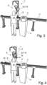
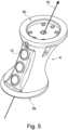
1 : eine perspektivische Ansicht eines erfindungsgemäßen Roboters zum Halten und Bearbeiten eines Werkstücks,2 : eine perspektivische Ansicht eines erfindungsgemäßen Roboters aus1 ,3 : eine perspektivische Ansicht eines weiteren erfindungsgemäßen Roboters zum Halten und Bearbeiten eines Werkstücks vor einer linearen Verschiebung,4 : eine perspektivische Ansicht eines erfindungsgemäßen Roboters aus3 ,5 : eine perspektivische Ansicht eines Griffstücks eines Manipulatorarms aus1 bis 4 .
1 : a perspective view of a robot according to the invention for holding and processing a workpiece,2 : a perspective view of a robot according to the invention from1 ,3 : a perspective view of another robot according to the invention for holding and machining a workpiece before a linear displacement,4 : a perspective view of a robot according to the invention from3 ,5 : a perspective view of a handle of a manipulator arm from1 until4 .
Der Roboter 1 umfasst einen mehrgliedrigen Manipulatorarm 5, eine Halteeinrichtung 4 und eine Steuerung. Der Roboter 1 ist ein Cobot und für die Mensch-Maschine-Interaktion geeignet.The robot 1 comprises a
In dieser und den weiteren Figuren ist die Steuerung nicht dargestellt. Die Steuerung erhält Informationen von dem Manipulatorarm, insbesondere Messwerte zur Position und zu Kräften, die auf den Manipulatorarm wirken und steuert diesen sowie die Halteeinrichtung 4.The controller is not shown in this and the following figures. The controller receives information from the manipulator arm, in particular measured values regarding the position and forces acting on the manipulator arm, and controls the manipulator arm and the holding
Die Halteeinrichtung 4 ist dazu eingerichtet und vorgesehen ein vom Roboter 1 zu bearbeitendes Werkstück 2 zu halten. Die Steuerung steuert die Halteeinrichtung 4 entsprechend an, sodass die Halteeinrichtung 4 das Werkstück entlang einer linearen Achse verfährt oder um eine Achse rotiert, also die Pose des Werkstücks relativ zum Manipulatorarm 5 ändert, wie es für die Bearbeitung mit einem Werkzeug nötig ist.The holding
Der Manipulatorarm 5 ist an seinem proximalen Ende 9 relativ zur Halteeinrichtung 4 festgelegt. An seinem distalen Ende 7 ist der Manipulatorarm zur Aufnahme eines Werkzeugs 8 eingerichtet. Mit dem Werkzeug 8 kann der Roboter 1 das Werkstück 2 bearbeiten, welches in der Halteeinrichtung 4 gehalten ist.The
Der Manipulatorarm 5 weist ein Griffstück 6 auf. Der Manipulatorarm 5 umfasst Motoren und Antriebe, um die Glieder des Manipulatorarms 5 zu verfahren oder zu rotieren. Weiterhin umfasst der Manipulatorarm 5 Sensoren und ist dazu eingerichtet von einem Bediener 18 auf das Griffstück 6 des Manipulatorarms 5 ausgeübte Kräfte zu ermitteln und entsprechende Informationen an die Steuerung zu übertragen. Die Kräfte können dabei entlang einer linearen Achse sein, d.h. wenn ein Bediener ein Kraft in einer gerade Richtung ausübt, beispielsweise wenn er eine Kraft zu einer Seite auf das Griffstück 6 und damit den Manipulatorarm 5 ausübt, also beispielsweise das Griffstück 6 von sich weg nach hinten drückt oder zu sich heranzieht. Die Richtung der Kraft kann dabei auch vertikal gerichtet sein, also nach oben oder unten.The
Alternativ kann eine Kraft rotatorisch sein, wenn also ein Bediener 18 ein Moment auf das Griffstück 6 ausübt, d.h. das Griffstück 6 um seine Mittelachse zu drehen versucht.Alternatively, a force can be rotational, i.e. when an
Der Roboter 1 lässt dabei zu, dass das Griffstück 6 in Richtung der ausgeübten linearen oder rotatorischen Kraft ausgelenkt wird. In einer Ausführungsform kann das Auslenken dadurch erfolgen, dass der Manipulatorarm 5 nicht vollständig starr, sondern flexibel gestaltet ist, wobei der Manipulatorarm 5 in seine entsprechende Ausgangsposition zurückkehrt, sobald die auslenkende Kraft nicht mehr ausgeübt wird.The robot 1 allows the
In einer alternativen Ausführungsform steuert die Steuerung des Roboters die Stellantriebe und Motoren des Manipulatorarms 5 so an, dass das Griffstück 6 entsprechend der ermittelten Kraft aus seiner Ausgangsposition ausgelenkt wird. Dementsprechend ist das Griffstück wieder zurück in seine Ausgangsposition zurückgefahren, sobald der Bediener 18 die Kraft auf das Griffstück 6 nicht mehr ausübt, In dieser Ausführungsform steuert die Steuerung des Roboters 1 die Wegstrecke oder den Rotationswinkel der Auslenkung linear oder nichtlinear zur ermittelten Kraft an.In an alternative embodiment, the robot's controller controls the actuators and motors of the
Bei einer Auslenkung proportional zur ermittelten Kraft ist die Länge der Wegstrecke oder der Rotationswinkel der Auslenkung direkt proportional zu der auf das Griffstück 6 ermittelten Kraft (lineare Zuordnung von Kraft zu Wegstrecke/Rotationswinkel). Bei einer doppelt so großen Kraft ist die Wegstrecke bzw. der Rotationswinkel der Auslenkung entsprechend doppelt so groß. Die Zuordnung von Wegstrecke bzw. Rotationswinkel zu einer ermittelten Kraft kann in einer weiteren Ausführungsform auch nicht proportional sein, sodass eine größere Kraft zwar einen größeren Auslenkweg oder Rotationswinkel bewirkt, die Zuordnung von Kraft zu Wegstrecke bzw. Rotationswinkel jedoch nicht linear ist. Mit einer solchen nicht proportionalen Ansteuerung kann die Steuerung die Wegstrecke der Auslenkung oder den Rotationswinkel so ansteuern, dass für die doppelte Wegstrecke der Auslenkung bzw. einen doppelt so großen Rotationswinkel viermal die ermittelte Kraft an dem Griffstück 6 anliegen muss.If the deflection is proportional to the determined force, the length of the path or the angle of rotation of the deflection is directly proportional to the force determined on the handle 6 (linear assignment of force to path/angle of rotation). If the force is twice as large, the path or angle of rotation of the deflection is correspondingly twice as large. In another embodiment, the assignment of path or angle of rotation to a determined force can also be non-proportional, so that while a greater force causes a greater deflection path or angle of rotation, the assignment of force to path or angle of rotation is not linear. With such non-proportional control, the controller can control the path of the deflection or the angle of rotation in such a way that for twice the path of the deflection or twice the angle of rotation, four times the determined force must be applied to the
Die Steuerung ist informativ, d.h. zum Austausch von ermittelten Information und Steueranweisungen, mit der Halteeinrichtung 4 verbunden. Die Halteeinrichtung 4 ist dazu eingerichtet das Werkstück 2 linear oder rotatorisch zu verfahren.The controller is connected to the
Die Steuerung ist dazu eingerichtet die Halteeinrichtung 4 und/oder den Manipulatorarm 5 anzusteuern. Dazu kann die Steuerung Steueranweisungen an die Halteeinrichtung 4 senden, sodass diese eine Position des Werkstücks 2 relativ zu dem Manipulatorarm 5 linear oder rotatorisch verfährt. Die Steuerung ist dazu eingerichtet, gleichzeitig mit der Ansteuerung der Halteeinrichtung 4 das Griffstück 6 des Manipulatorarms 5 ebenso basierend auf den über den Manipulatorarm 5 ermittelten Kräfte linear oder rotatorisch aus einer Ausgangsposition auszulenken.The controller is configured to control the holding
Der Manipulatorarm 5 ist an seinem distalen Ende 7 dazu vorgesehen und eingerichtet ein Werkzeug 8 zu halten oder aufzunehmen, mit dem das Werkstück 2 bearbeitet werden kann. Das Auslenken des Manipulatorarms 5, d.h. der Weg der Auslenkung, in einer Ausführungsform ist nicht proportional zu den auf den Manipulatorarm 5 ausgeübten und ermittelten Kräfte.The
Wie in
Wie in
Typischerweise ist das Griffstück 6 in dem Manipulatorarm zwischen dem letzten Glied des Manipulatorarms und einem Werkzeug 8 angeordnet, welches der Manipulatorarm hält.Typically, the
BezugszeichenlisteList of reference symbols
- 11
- Roboter, CobotRobot, Cobot
- 22
- Werkstückworkpiece
- 33
- Steuerungsteering
- 44
- HalteeinrichtungHolding device
- 55
- ManipulatorarmManipulator arm
- 66
- Griffstückhandle
- 6a,6b6a,6b
- MontageflächenMounting surfaces
- 77
- distales Endedistal end
- 88
- WerkzeugTool
- 99
- proximales Endeproximal end
- 1010
- Schalter, DrucktasterSwitch, push button
- 1111
- LinearführungLinear guide
- 1212
- erste Drehbewegungfirst rotational movement
- 1313
- zweite Drehbewegungsecond rotation
- 1414
- Kraft auf das GriffstückForce on the handle
- 1515
- Bewegungsrichtung des ManipulatorarmsDirection of movement of the manipulator arm
- 1616
- Achse des GriffstücksAxis of the handle
- 1717
- Sensoren, KraftmesserdoseSensors, force gauge
- 1818
- Bedieneroperator
Claims (13)
Translated fromGermanPriority Applications (3)
| Application Number | Priority Date | Filing Date | Title |
|---|---|---|---|
| DE102023127790.1ADE102023127790A1 (en) | 2023-10-11 | 2023-10-11 | Robot arm control with haptic feedback to an operator during control |
| EP24205868.3AEP4538816A1 (en) | 2023-10-11 | 2024-10-10 | Robotic arm controller with haptic feedback to an operator upon control |
| US18/913,482US20250121495A1 (en) | 2023-10-11 | 2024-10-11 | Robot arm controller with haptic feedback to an operator during control |
Applications Claiming Priority (1)
| Application Number | Priority Date | Filing Date | Title |
|---|---|---|---|
| DE102023127790.1ADE102023127790A1 (en) | 2023-10-11 | 2023-10-11 | Robot arm control with haptic feedback to an operator during control |
Publications (1)
| Publication Number | Publication Date |
|---|---|
| DE102023127790A1true DE102023127790A1 (en) | 2025-04-17 |
Family
ID=93100655
Family Applications (1)
| Application Number | Title | Priority Date | Filing Date |
|---|---|---|---|
| DE102023127790.1APendingDE102023127790A1 (en) | 2023-10-11 | 2023-10-11 | Robot arm control with haptic feedback to an operator during control |
Country Status (3)
| Country | Link |
|---|---|
| US (1) | US20250121495A1 (en) |
| EP (1) | EP4538816A1 (en) |
| DE (1) | DE102023127790A1 (en) |
Citations (10)
| Publication number | Priority date | Publication date | Assignee | Title |
|---|---|---|---|---|
| EP1987406B1 (en)* | 2006-02-23 | 2010-08-04 | Abb Ab | A system for controlling the position and orientation of an object in dependence on received forces and torques from a user |
| US20150211847A1 (en)* | 2014-01-29 | 2015-07-30 | Mitutoyo Corporation | Manual measuring system |
| DE102014202145A1 (en)* | 2014-02-06 | 2015-08-06 | Kuka Roboter Gmbh | A method of programming an industrial robot and associated industrial robots |
| DE102008027008B4 (en)* | 2008-06-06 | 2016-03-17 | Kuka Roboter Gmbh | Method and device for controlling a manipulator |
| DE102015205176B3 (en)* | 2015-03-23 | 2016-05-12 | Kuka Roboter Gmbh | Robust intuitive operating method by touching a manipulator |
| DE202016002733U1 (en)* | 2016-04-22 | 2017-07-26 | Kuka Roboter Gmbh | End effector means |
| DE112011100295B4 (en)* | 2010-01-20 | 2018-01-11 | Faro Technologies Inc. | Portable articulated arm coordinate measuring machine and integrated electronic data processing system |
| DE102017003000B4 (en)* | 2016-03-30 | 2019-07-25 | Fanuc Corporation | Robotic system cooperating with humans |
| EP2916099B1 (en)* | 2014-03-07 | 2020-09-30 | Hexagon Technology Center GmbH | Articulated arm coordinate measuring machine |
| US20230142821A1 (en)* | 2021-11-10 | 2023-05-11 | James Walter Beard, III | Method for Precise, Intuitive Positioning of Robotic Welding Machine |
Family Cites Families (2)
| Publication number | Priority date | Publication date | Assignee | Title |
|---|---|---|---|---|
| JP4443615B2 (en)* | 2008-02-27 | 2010-03-31 | トヨタ自動車株式会社 | Power assist device and control method thereof |
| DE102010029745A1 (en)* | 2010-06-07 | 2011-12-08 | Kuka Laboratories Gmbh | Workpiece handling system and method for manipulating workpieces by means of cooperating manipulators |
- 2023
- 2023-10-11DEDE102023127790.1Apatent/DE102023127790A1/enactivePending
- 2024
- 2024-10-10EPEP24205868.3Apatent/EP4538816A1/enactivePending
- 2024-10-11USUS18/913,482patent/US20250121495A1/enactivePending
Patent Citations (10)
| Publication number | Priority date | Publication date | Assignee | Title |
|---|---|---|---|---|
| EP1987406B1 (en)* | 2006-02-23 | 2010-08-04 | Abb Ab | A system for controlling the position and orientation of an object in dependence on received forces and torques from a user |
| DE102008027008B4 (en)* | 2008-06-06 | 2016-03-17 | Kuka Roboter Gmbh | Method and device for controlling a manipulator |
| DE112011100295B4 (en)* | 2010-01-20 | 2018-01-11 | Faro Technologies Inc. | Portable articulated arm coordinate measuring machine and integrated electronic data processing system |
| US20150211847A1 (en)* | 2014-01-29 | 2015-07-30 | Mitutoyo Corporation | Manual measuring system |
| DE102014202145A1 (en)* | 2014-02-06 | 2015-08-06 | Kuka Roboter Gmbh | A method of programming an industrial robot and associated industrial robots |
| EP2916099B1 (en)* | 2014-03-07 | 2020-09-30 | Hexagon Technology Center GmbH | Articulated arm coordinate measuring machine |
| DE102015205176B3 (en)* | 2015-03-23 | 2016-05-12 | Kuka Roboter Gmbh | Robust intuitive operating method by touching a manipulator |
| DE102017003000B4 (en)* | 2016-03-30 | 2019-07-25 | Fanuc Corporation | Robotic system cooperating with humans |
| DE202016002733U1 (en)* | 2016-04-22 | 2017-07-26 | Kuka Roboter Gmbh | End effector means |
| US20230142821A1 (en)* | 2021-11-10 | 2023-05-11 | James Walter Beard, III | Method for Precise, Intuitive Positioning of Robotic Welding Machine |
Also Published As
| Publication number | Publication date |
|---|---|
| EP4538816A1 (en) | 2025-04-16 |
| US20250121495A1 (en) | 2025-04-17 |
Similar Documents
| Publication | Publication Date | Title |
|---|---|---|
| DE102008062622B4 (en) | Method and device for entering commands into a controller of a manipulator | |
| DE102018107231B4 (en) | robot teaching device | |
| EP1950010B1 (en) | Robot and method for programming a robot | |
| EP2862677B1 (en) | Method for handling objects using at least two industrial robots | |
| DE69936073T2 (en) | robot control | |
| EP2223191B1 (en) | Industrial robot and method for programming an industrial robot | |
| EP2868445B1 (en) | Method for programming sequences of movements of a redundant industrial robot and associated industrial robot | |
| DE102008027008B4 (en) | Method and device for controlling a manipulator | |
| EP2000872B1 (en) | Industrial robot and method for programming an industrial robot | |
| WO2010069429A1 (en) | Method and device for inputting commands into a control of a manipulator | |
| DE102018007842B4 (en) | Control device for monitoring the direction of movement of an operating tool | |
| EP2851162A2 (en) | Method for manually handled adjustment of the pose of an industrial robot manipulator arm of an industrial robot and associated industrial robot | |
| DE102015004481B4 (en) | A robot control device for controlling a robot moved in accordance with an applied force | |
| EP2392435A2 (en) | Tool handling system and method for manipulating workpieces by means of cooperating manipulators | |
| EP2008778B1 (en) | Method and device for programming an industrial robot | |
| DE102020206568B4 (en) | Programming system for manually programming a movement of an industrial robot, industrial robot with such a programming system and method for manually programming a movement of an industrial robot | |
| DE102015117306B4 (en) | Multi-axis mouse for a multi-axis robot | |
| DE69121520T2 (en) | METHOD FOR CONTROLLING THE NOZZLE MOVEMENT OF A LASER JET MACHINE | |
| DE102023127790A1 (en) | Robot arm control with haptic feedback to an operator during control | |
| EP3045995A1 (en) | Measuring method comprising a combination of prepositioning and hand guiding | |
| EP2507008B1 (en) | Welding device having a generator for determining and transmitting co-ordinates of welding line points | |
| DE102018009767A1 (en) | Process for processing objects using an industrial robot | |
| DE102015003941A1 (en) | Controlling a mobile redundant robot | |
| EP2447797B1 (en) | Control device for a machine tool | |
| DE102007026117B4 (en) | machine tool |
Legal Events
| Date | Code | Title | Description |
|---|---|---|---|
| R163 | Identified publications notified |