DE102023127507A1 - ADJUSTABLE SEAT PAD INSERT - Google Patents
ADJUSTABLE SEAT PAD INSERTDownload PDFInfo
- Publication number
- DE102023127507A1 DE102023127507A1DE102023127507.0ADE102023127507ADE102023127507A1DE 102023127507 A1DE102023127507 A1DE 102023127507A1DE 102023127507 ADE102023127507 ADE 102023127507ADE 102023127507 A1DE102023127507 A1DE 102023127507A1
- Authority
- DE
- Germany
- Prior art keywords
- cushion
- insert frame
- hole
- cushion insert
- seat cushion
- Prior art date
- Legal status (The legal status is an assumption and is not a legal conclusion. Google has not performed a legal analysis and makes no representation as to the accuracy of the status listed.)
- Pending
Links
- 230000000712assemblyEffects0.000description1
- 238000000429assemblyMethods0.000description1
- 238000002485combustion reactionMethods0.000description1
- 230000000694effectsEffects0.000description1
- 238000009434installationMethods0.000description1
- 239000000463materialSubstances0.000description1
- 238000012986modificationMethods0.000description1
- 230000004048modificationEffects0.000description1
- 239000000758substrateSubstances0.000description1
Images


Classifications
- B—PERFORMING OPERATIONS; TRANSPORTING
- B60—VEHICLES IN GENERAL
- B60N—SEATS SPECIALLY ADAPTED FOR VEHICLES; VEHICLE PASSENGER ACCOMMODATION NOT OTHERWISE PROVIDED FOR
- B60N2/00—Seats specially adapted for vehicles; Arrangement or mounting of seats in vehicles
- B60N2/90—Details or parts not otherwise provided for
- B—PERFORMING OPERATIONS; TRANSPORTING
- B60—VEHICLES IN GENERAL
- B60N—SEATS SPECIALLY ADAPTED FOR VEHICLES; VEHICLE PASSENGER ACCOMMODATION NOT OTHERWISE PROVIDED FOR
- B60N2/00—Seats specially adapted for vehicles; Arrangement or mounting of seats in vehicles
- B60N2/62—Thigh-rests
- B—PERFORMING OPERATIONS; TRANSPORTING
- B60—VEHICLES IN GENERAL
- B60N—SEATS SPECIALLY ADAPTED FOR VEHICLES; VEHICLE PASSENGER ACCOMMODATION NOT OTHERWISE PROVIDED FOR
- B60N2/00—Seats specially adapted for vehicles; Arrangement or mounting of seats in vehicles
- B60N2/02—Seats specially adapted for vehicles; Arrangement or mounting of seats in vehicles the seat or part thereof being movable, e.g. adjustable
- B—PERFORMING OPERATIONS; TRANSPORTING
- B60—VEHICLES IN GENERAL
- B60N—SEATS SPECIALLY ADAPTED FOR VEHICLES; VEHICLE PASSENGER ACCOMMODATION NOT OTHERWISE PROVIDED FOR
- B60N2/00—Seats specially adapted for vehicles; Arrangement or mounting of seats in vehicles
- B60N2/90—Details or parts not otherwise provided for
- B60N2/919—Positioning and locking mechanisms
- B60N2002/952—Positioning and locking mechanisms characterised by details of the locking system
Landscapes
- Engineering & Computer Science (AREA)
- Aviation & Aerospace Engineering (AREA)
- Transportation (AREA)
- Mechanical Engineering (AREA)
- Seats For Vehicles (AREA)
Abstract
Translated fromGermanDescription
Translated fromGermanEINLEITUNGINTRODUCTION
Der Gegenstand der Offenbarung bezieht sich auf eine Sitzanordnung in einem Fahrzeug und insbesondere auf einen Mechanismus zum Einstellen eines Sitzpolstereinsatzes der Sitzanordnung.The subject matter of the disclosure relates to a seating assembly in a vehicle, and more particularly to a mechanism for adjusting a seat cushion insert of the seating assembly.
Fahrzeugsitze umfassen im Allgemeinen ein Sitzpolster und eine Sitzlehne. Das Sitzpolster ist eine einzelne Komponente mit nicht beweglichen Teilen. Eine Person, die auf dem Sitz sitzt, möchte vielleicht einen Polstereinsatz einstellen lassen. Da Sitze im Allgemeinen in einer Einheitsgröße konzipiert sind, könnte sich für manche Menschen ein Sitz unbequem anfühlen, wenn er nicht angepasst werden kann. Dementsprechend ist es wünschenswert, einen Mechanismus zum Einstellen eines Polstereinsatzes des Sitzes bereitzustellen, um den Komfort für eine Reihe von Personen zu verbessern und den richtigen Einbau eines Kindersitzes zu ermöglichen.Vehicle seats generally include a seat cushion and a seat back. The seat cushion is a single component with non-moving parts. A person sitting on the seat may want to have a bolster insert adjusted. Since seats are generally designed to be one size fits all, some people may find a seat uncomfortable if it cannot be adjusted. Accordingly, it is desirable to provide a mechanism for adjusting a bolster insert of the seat to improve comfort for a range of people and to allow for proper installation of a child seat.
KURZDARSTELLUNGSUMMARY
In einer beispielhaften Ausführungsform wird eine Sitzanordnung für ein Fahrzeug offenbart. Die Sitzanordnung umfasst ein Sitzpolster, einen mit dem Sitzpolster drehbar gekoppelten Polstereinsatzrahmen und eine Verriegelungsvorrichtung, um den Polstereinsatzrahmen mit dem Sitzpolster in Eingriff zu bringen und den Polstereinsatzrahmen vom Sitzpolster zu lösen, um das Einstellen eines Winkels des Polstereinsatzrahmens in Bezug auf das Sitzpolster zu ermöglichen.In an exemplary embodiment, a seat assembly for a vehicle is disclosed. The seat assembly includes a seat cushion, a cushion insert frame rotatably coupled to the seat cushion, and a locking device for engaging the cushion insert frame with the seat cushion and disengaging the cushion insert frame from the seat cushion to enable adjustment of an angle of the cushion insert frame with respect to the seat cushion.
Zusätzlich zu einem oder mehreren der hier beschriebenen Merkmale umfasst das Sitzpolster eine Halterung mit einem Loch, und der Polstereinsatzrahmen umfasst einen Zylinder mit einem Stift und einer Feder, die eine Vorspannkraft auf den Zylinder ausübt, um den Stift mit dem Loch in Eingriff zu bringen, sowie einen Gurt zum Ausüben einer Gegenkraft auf den Zylinder gegen die Vorspannkraft, um den Stift aus dem Loch zu lösen. Der Zylinder ist an einem Ende einer Stange angeordnet, die mit dem Polstereinsatzrahmen gekoppelt ist, und die Feder ist zwischen dem Zylinder und dem Ende der Stange angeordnet. Die Sitzanordnung umfasst ferner einen Motor zum Ausüben der Gegenkraft auf den Gurt. Das Sitzpolster umfasst eine Halterung mit einem Loch und der Polstereinsatzrahmen umfasst einen Hebelarm, der schwenkbar am Polstereinsatzrahmen befestigt ist, eine Feder, die eine Vorspannkraft auf den Hebelarm ausübt, um einen Stift des Hebelarms mit dem Loch in Eingriff zu bringen, und einen Gurt zum Ausüben einer Gegenkraft auf den Hebelarm gegen die Vorspannkraft, um den Stift aus dem Loch zu lösen. Die Feder ist zwischen einem Ende einer mit dem Polstereinsatzrahmen gekoppelten Stange und dem Hebelarm angeordnet. Die Sitzanordnung umfasst ferner einen Motor zum Ausüben der Gegenkraft auf den Gurt. Die Sitzanordnung umfasst ferner eine horizontale Leiste, die am Boden des Fahrzeugs befestigt ist, und einen Riegel, der schwenkbar am Polstereinsatzrahmen befestigt ist, wobei der Riegel mindestens eine erste Aussparung und eine zweite Aussparung zur Aufnahme der horizontalen Leiste und einen Griff zum Verriegeln des Riegels in seiner Position aufweist. Die Sitzanordnung umfasst ferner eine horizontale Leiste, die am Polstereinsatzrahmen befestigt ist, und einen Riegel, der schwenkbar am Fahrzeugboden befestigt ist, wobei der Riegel mindestens eine erste Aussparung und eine zweite Aussparung zur Aufnahme der horizontalen Leiste und einen Griff zum Verriegeln des Riegels in seiner Position aufweist. Die Verriegelungsvorrichtung ist an einem vorderen Ende des Polstereinsatzrahmens angeordnet.In addition to one or more of the features described herein, the seat cushion includes a bracket having a hole, and the cushion insert frame includes a cylinder having a pin and a spring that applies a biasing force to the cylinder to engage the pin with the hole, and a belt for applying a counterforce to the cylinder against the biasing force to release the pin from the hole. The cylinder is disposed at one end of a rod coupled to the cushion insert frame, and the spring is disposed between the cylinder and the end of the rod. The seat assembly further includes a motor for applying the counterforce to the belt. The seat cushion includes a bracket having a hole, and the cushion insert frame includes a lever arm pivotally attached to the cushion insert frame, a spring that applies a biasing force to the lever arm to engage a pin of the lever arm with the hole, and a belt for applying a counterforce to the lever arm against the biasing force to release the pin from the hole. The spring is disposed between an end of a rod coupled to the bolster frame and the lever arm. The seat assembly further includes a motor for applying the counterforce to the belt. The seat assembly further includes a horizontal bar attached to the floor of the vehicle and a latch pivotally attached to the bolster frame, the latch having at least a first recess and a second recess for receiving the horizontal bar and a handle for locking the latch in position. The seat assembly further includes a horizontal bar attached to the bolster frame and a latch pivotally attached to the vehicle floor, the latch having at least a first recess and a second recess for receiving the horizontal bar and a handle for locking the latch in position. The locking device is disposed at a front end of the bolster frame.
In einer weiteren beispielhaften Ausführungsform ist ein Fahrzeug offenbart. Das Fahrzeug umfasst ein Sitzpolster, einen mit dem Sitzpolster drehbar gekoppelten Polstereinsatzrahmen und eine Verriegelungsvorrichtung, um den Polstereinsatzrahmen mit dem Sitzpolster in Eingriff zu bringen und den Polstereinsatzrahmen vom Sitzpolster zu lösen, um das Einstellen eines Winkels des Polstereinsatzrahmens in Bezug auf das Sitzpolster zu ermöglichen.In another exemplary embodiment, a vehicle is disclosed. The vehicle includes a seat cushion, a cushion insert frame rotatably coupled to the seat cushion, and a locking device for engaging the cushion insert frame with the seat cushion and disengaging the cushion insert frame from the seat cushion to enable adjustment of an angle of the cushion insert frame with respect to the seat cushion.
Zusätzlich zu einem oder mehreren der hier beschriebenen Merkmale umfasst das Sitzpolster eine Halterung mit einem Loch, und der Polstereinsatzrahmen umfasst einen Zylinder mit einem Stift und einer Feder, die eine Vorspannkraft auf den Zylinder ausübt, um den Stift mit dem Loch in Eingriff zu bringen, sowie einen Gurt zum Ausüben einer Gegenkraft auf den Zylinder gegen die Vorspannkraft, um den Stift aus dem Loch zu lösen. Der Zylinder ist an einem Ende einer Stange angeordnet, die mit dem Polstereinsatzrahmen gekoppelt ist, und die Feder ist zwischen dem Zylinder und dem Ende der Stange angeordnet. Das Fahrzeug umfasst ferner einen Motor zum Ausüben der Gegenkraft auf den Gurt. Das Sitzpolster umfasst eine Halterung mit einem Loch und der Polstereinsatzrahmen umfasst einen Hebelarm, der schwenkbar am Polstereinsatzrahmen befestigt ist, eine Feder, die eine Vorspannkraft auf den Hebelarm ausübt, um einen Stift des Hebelarms mit dem Loch in Eingriff zu bringen, und einen Gurt zum Ausüben einer Gegenkraft auf den Hebelarm gegen die Vorspannkraft, um den Stift aus dem Loch zu lösen. Die Feder ist zwischen einem Ende einer mit dem Polstereinsatzrahmen gekoppelten Stange und dem Hebelarm angeordnet. Das Fahrzeug umfasst ferner einen Motor zum Ausüben der Gegenkraft auf den Gurt. Das Fahrzeug umfasst ferner eine horizontale Leiste, die am Boden des Fahrzeugs befestigt ist, und einen Riegel, der schwenkbar am Polstereinsatzrahmen befestigt ist, wobei der Riegel mindestens eine erste Aussparung und eine zweite Aussparung zur Aufnahme der horizontalen Leiste und einen Griff zum Verriegeln des Riegels in seiner Position aufweist. Das Fahrzeug umfasst ferner eine horizontale Leiste, die am Polstereinsatzrahmen befestigt ist, und einen Riegel, der schwenkbar am Boden des Fahrzeugs befestigt ist, wobei der Riegel mindestens eine erste Aussparung und eine zweite Aussparung zur Aufnahme der horizontalen Leiste und einen Griff zum Verriegeln des Riegels in seiner Position aufweist. Die Verriegelungsvorrichtung ist an einem vorderen Ende des Polstereinsatzrahmens angeordnet.In addition to one or more of the features described herein, the seat cushion includes a bracket having a hole, and the cushion insert frame includes a cylinder having a pin and a spring that applies a biasing force to the cylinder to engage the pin with the hole, and a belt for applying a counterforce to the cylinder against the biasing force to release the pin from the hole. The cylinder is disposed at one end of a rod coupled to the cushion insert frame, and the spring is disposed between the cylinder and the end of the rod. The vehicle further includes a motor for applying the counterforce to the belt. The seat cushion includes a bracket having a hole, and the cushion insert frame includes a lever arm pivotally attached to the cushion insert frame, a spring that applies a biasing force to the lever arm to engage a pin of the lever arm with the hole, and a belt for applying a counterforce to the lever arm against the biasing force to release the pin from the hole. The spring is arranged between one end of a rod coupled to the cushion insert frame and the lever arm. The vehicle further comprises a motor for exerting the counterforce on the belt. The vehicle further comprises a horizontal bar which is floor of the vehicle, and a latch pivotally attached to the cushion insert frame, the latch having at least a first recess and a second recess for receiving the horizontal bar and a handle for locking the latch in position. The vehicle further includes a horizontal bar attached to the cushion insert frame, and a latch pivotally attached to the floor of the vehicle, the latch having at least a first recess and a second recess for receiving the horizontal bar and a handle for locking the latch in position. The locking device is arranged at a front end of the cushion insert frame.
Die vorstehend genannten Merkmale und Vorteile, sowie andere Merkmale und Vorteile der Offenbarung sind aus der folgenden detaillierten Beschreibung in Verbindung mit den beigefügten Zeichnungen ohne weiteres ersichtlich.The above features and advantages, as well as other features and advantages of the disclosure, are readily apparent from the following detailed description taken in conjunction with the accompanying drawings.
KURZBESCHREIBUNG DER ZEICHNUNGENBRIEF DESCRIPTION OF THE DRAWINGS
Weitere Merkmale, Vorteile und Details sind nur beispielhaft in der folgenden detaillierten Beschreibung aufgeführt, wobei sich die detaillierte Beschreibung auf die Zeichnungen bezieht, in denen gilt:
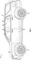
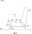
1 zeigt ein Fahrzeug gemäß einer beispielhaften Ausführungsform,2 zeigt eine Seitenansicht einer Sitzanordnung des Fahrzeugs in einer beispielhaften Ausführungsform;3 zeigt eine perspektivische Ansicht eines Sitzpolsters der Sitzanordnung;4 zeigt eine Vorderansicht eines Verstellmechanismus des Sitzpolsters in einer ersten Position;5 zeigt eine Vorderansicht des Verstellmechanismus des Sitzpolsters in einer zweiten Position;6 zeigt eine Vorderansicht einer Verriegelungsvorrichtung in verriegelter Konfiguration;7 zeigt eine Vorderansicht der Verriegelungsvorrichtung in entriegelter Konfiguration;8 zeigt eine Vorderansicht der Verriegelungsvorrichtung in einer alternativen Ausführungsform in verriegelter Konfiguration;9 zeigt eine Vorderansicht der Verriegelungsvorrichtung in der alternativen Ausführungsform in entriegelter Konfiguration;10 zeigt eine Vorderansicht einer schwenkbaren Verriegelungsvorrichtung für den Verstellmechanismus in verriegelter Konfiguration;11 zeigt eine Vorderansicht der schwenkbaren Verriegelungsvorrichtung in entriegelter Konfiguration;12 zeigt eine Vorderansicht der schwenkbaren Verriegelungsvorrichtung in einer alternativen Ausführungsform, wobei sich die Verriegelungsvorrichtung in verriegelter Konfiguration befindet;13 zeigt eine Vorderansicht der schwenkbaren Verriegelungsvorrichtung in entriegelter Konfiguration;14 zeigt eine Seitenansicht des Sitzpolsters, die einen ersten Verriegelungsmechanismus zum Verändern der Höhe eines Polstereinsatzes darstellt;15 zeigt eine Vorderansicht des ersten Verriegelungsmechanismus in einer ersten Konfiguration;16 zeigt eine Vorderansicht des ersten Verriegelungsmechanismus in einer zweiten Konfiguration;17 zeigt eine Seitenansicht eines zweiten Verriegelungsmechanismus zum Verändern der Höhe eines Polstereinsatzes;18 zeigt eine Vorderansicht des zweiten Verriegelungsmechanismus in einer ersten Konfiguration; und19 zeigt eine Vorderansicht des zweiten Verriegelungsmechanismus in einer zweiten Konfiguration.
1 shows a vehicle according to an exemplary embodiment,2 shows a side view of a seating arrangement of the vehicle in an exemplary embodiment;3 shows a perspective view of a seat cushion of the seating assembly;4 shows a front view of an adjustment mechanism of the seat cushion in a first position;5 shows a front view of the seat cushion adjustment mechanism in a second position;6 shows a front view of a locking device in locked configuration;7 shows a front view of the locking device in unlocked configuration;8 shows a front view of the locking device in an alternative embodiment in locked configuration;9 shows a front view of the locking device in the alternative embodiment in unlocked configuration;10 shows a front view of a pivotable locking device for the adjustment mechanism in locked configuration;11 shows a front view of the pivoting locking device in unlocked configuration;12 shows a front view of the pivotable locking device in an alternative embodiment, wherein the locking device is in a locked configuration;13 shows a front view of the pivoting locking device in unlocked configuration;14 shows a side view of the seat cushion, illustrating a first locking mechanism for changing the height of a cushion insert;15 shows a front view of the first locking mechanism in a first configuration;16 shows a front view of the first locking mechanism in a second configuration;17 shows a side view of a second locking mechanism for changing the height of a cushion insert;18 shows a front view of the second locking mechanism in a first configuration; and19 shows a front view of the second locking mechanism in a second configuration.
DETAILLIERTE BESCHREIBUNGDETAILED DESCRIPTION
Die folgende Beschreibung hat lediglich beispielhaften Charakter und ist nicht dazu bestimmt, die vorliegende Offenbarung, ihre Anwendung oder ihren Gebrauch einzuschränken. Es versteht sich, dass in den Zeichnungen entsprechende Bezugszeichen gleiche oder entsprechende Teile und Merkmale angeben.The following description is merely exemplary and is not intended to limit the present disclosure, its application, or uses. It is to be understood that throughout the drawings, corresponding reference characters indicate like or corresponding parts and features.
Gemäß einer beispielhaften Ausführungsform ist ein Fahrzeug 10 in
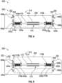
Der Verstellmechanismus 214 umfasst eine Verriegelungsvorrichtung 410 zum Eingreifen in die und Lösen aus der rechte(n) Halterung 402 und der linke(n) Halterung 404. Die Verriegelungsvorrichtung 410 umfasst eine Stange 412, die über ein Auflager 414 am Polstereinsatz 208 oder am Polstereinsatzrahmen 306 befestigt ist. Die Stange 412 liegt horizontal und ist in der ersten Position des Polsters mit einander gegenüberliegenden Löchern ausgerichtet (z. B. das erste rechte Loch 406a und das erste linke Loch 406b). Ein rechter Zylinder 416a (oder eine rechte Kappe) ist an einem rechten Ende 418a der Stange 412 angeordnet und umfasst eine rechte Feder 420a, die eine Vorspannkraft ausübt, die den rechten Zylinder vom rechten Ende weg vorspannt. Der rechte Zylinder 416a umfasst an seinem äußeren Ende einen rechten Stift 422a, der in die Löcher (z. B. das erste rechte Loch 406a) der rechten Halterung 402 eingeführt wird.The
In ähnlicher Weise ist ein linker Zylinder 416b (oder eine linke Kappe) am linken Ende 418b der Stange 412 angeordnet und enthält eine linke Feder 420b, die eine Vorspannkraft ausübt, die den zweiten Zylinder vom zweiten Ende weg vorspannt. Der linke Zylinder 416b umfasst an seinem äußeren Ende einen linken Stift 422b, der in die Löcher (z. B. das erste linke Loch 406b) der linken Halterung 404 eingeführt wird.Similarly, a
In der ersten Position befindet sich der Polstereinsatz 208 in Bezug auf das Sitzpolster 202 in einer „unteren“ Position. Der rechte Stift 422a ist in dem ersten rechten Loch 406a und der linke Stift 422b in dem ersten linken Loch 406b angeordnet.In the first position, the
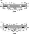
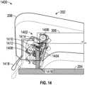
In
Ein rechter Gurt 1012a verbindet ein freies Ende 1014a des rechten Hebelarms 1004a mit einer Drehvorrichtung 1020. In ähnlicher Weise verbindet ein linker Gurt 1012b ein freies Ende 1014b des linken Hebelarms 1004b mit der Drehvorrichtung 1020. Wie in
Der erste Haken 1408 bildet eine erste Aussparung 1412 und der zweite Haken 1410 bildet eine zweite Aussparung 1414. Am Boden 204 ist eine Schlaufe 1416 befestigt. Der Riegel 1404 kann nach vorne gebracht werden, um einen horizontalen Abschnitt der Schlaufe 1416 entweder in der ersten Aussparung 1412 oder in der zweiten Aussparung 1414 zu erfassen. Ein Griff 1418 wird zum Ver- und Entriegeln des Riegels 1404 verwendet. Der Griff 1418 kann in einer ersten Position platziert werden, um den Riegel 1404 in seiner Position zu verriegeln, und in einer zweiten Position, damit sich der Riegel frei um das Scharnier 1406 drehen kann. Nachdem der Polstereinsatz 208 auf eine gewünschte Höhe eingestellt ist, wird der Riegel 1404 nach vorne gebracht, um den horizontalen Abschnitt der Schlaufe 1416 zu erfassen, und der Griff 1418 wird in die erste Position gebracht, um den Riegel in seiner Position zu verriegeln.The
Eine Schlaufe 1716 ist am Polstereinsatzrahmen 306 befestigt. Der Riegel 1704 kann nach vorne gebracht werden, um einen horizontalen Abschnitt der Schlaufe 1716 entweder in der ersten Aussparung 1712 oder in der zweiten Aussparung 1714 zu erfassen. Ein Griff 1718 kann in eine erste Position gebracht werden, um den Riegel 1704 in seiner Position zu verriegeln, und in eine zweite Position, damit sich der Riegel um das Scharnier 1706 drehen kann.A
Die Begriffe „ein“ und „eine“ bedeuten keine Mengenbegrenzung, sondern bezeichnen das Vorhandensein von mindestens einem der genannten Gegenstände. Der Begriff „oder“ bedeutet „und/oder“, sofern sich aus dem Kontext nicht eindeutig etwas anderes ergibt. Wenn in der gesamten Beschreibung von „einem Aspekt“ die Rede ist, bedeutet dies, dass ein bestimmtes Element (z. B. ein Merkmal, eine Struktur, ein Schritt oder eine Eigenschaft), das im Zusammenhang mit dem Aspekt beschrieben wird, in mindestens einem der hier beschriebenen Aspekte enthalten ist und in anderen Aspekten vorliegen kann oder nicht. Es versteht sich, dass die beschriebenen Elemente in den verschiedenen Aspekten auf jede geeignete Weise kombiniert werden können.The terms "a" and "an" do not imply a limitation of quantity, but denote the presence of at least one of the items mentioned. The term "or" means "and/or" unless the context clearly indicates otherwise. Whenever "an aspect" is mentioned throughout the description, it means that a particular element (e.g. a feature, structure, step or property) described in connection with the aspect is included in at least one of the aspects described herein and may or may not be present in other aspects. It is understood that the elements described in the various aspects may be combined in any suitable way.
Wenn ein Element wie eine Schicht, ein Film, eine Region oder ein Substrat als „auf“ einem anderen Element liegend bezeichnet wird, kann es direkt auf dem anderen Element liegen oder es können auch dazwischenliegende Elemente vorhanden sein. Im Gegensatz dazu gibt es keine dazwischenliegenden Elemente, wenn ein Element als „direkt auf“ einem anderen Element liegend bezeichnet wird.When an element such as a layer, film, region, or substrate is referred to as lying "on" another element, it may lie directly on the other element, or there may also be intervening elements. In contrast, when an element is referred to as lying "directly on" another element, there are no intervening elements.
Sofern hier nicht anders angegeben, sind alle Prüfnormen die neueste Norm, die zum Anmeldetag dieser Anmeldung in Kraft ist, oder, wenn eine Priorität beansprucht wird, zum Anmeldetag der frühesten Prioritätsanmeldung, in der die Prüfnorm erscheint.Unless otherwise indicated herein, all testing standards are the most recent standard in effect as of the filing date of this application or, if priority is claimed, as of the filing date of the earliest priority application in which the testing standard appears.
Sofern nicht anders definiert, haben die hier verwendeten technischen und wissenschaftlichen Begriffe die gleiche Bedeutung, wie sie von einem Fachkundigen auf dem Gebiet, zu dem diese Offenbarung gehört, allgemein verstanden wird.Unless otherwise defined, technical and scientific terms used herein have the same meaning as commonly understood by one of ordinary skill in the art to which this disclosure belongs.
Während die vorstehende Offenbarung unter Bezugnahme auf beispielhafte Ausführungsformen beschrieben wurde, ist unter Fachkundigen bekannt, dass verschiedene Änderungen vorgenommen und Elemente durch gleichwertige ersetzt werden können, ohne von deren Umfang abzuweichen. Darüber hinaus können viele Modifizierungen vorgenommen werden, um eine bestimmte Situation oder ein bestimmtes Material an die Lehren der Offenbarung anzupassen, ohne von deren wesentlichem Umfang abzuweichen. Daher soll die vorliegende Offenbarung nicht auf die besonderen offenbarten Ausführungsformen beschränkt sein, sondern alle Ausführungsformen umfassen, die in ihren Umfang fallen.While the foregoing disclosure has been described with reference to exemplary embodiments, it will be appreciated by those skilled in the art that various changes may be made and equivalents may be substituted for elements without departing from the scope thereof. Moreover, many modifications may be made to adapt a particular situation or material to the teachings of the disclosure without departing from the essential scope thereof. Therefore, the present disclosure is not intended to be limited to the particular embodiments disclosed, but will include all embodiments falling within its scope.
Claims (10)
Translated fromGermanApplications Claiming Priority (2)
| Application Number | Priority Date | Filing Date | Title |
|---|---|---|---|
| US18/354,149 | 2023-07-18 | ||
| US18/354,149US20250026245A1 (en) | 2023-07-18 | 2023-07-18 | Adjustable seat cushion insert |
Publications (1)
| Publication Number | Publication Date |
|---|---|
| DE102023127507A1true DE102023127507A1 (en) | 2025-01-23 |
Family
ID=94170585
Family Applications (1)
| Application Number | Title | Priority Date | Filing Date |
|---|---|---|---|
| DE102023127507.0APendingDE102023127507A1 (en) | 2023-07-18 | 2023-10-09 | ADJUSTABLE SEAT PAD INSERT |
Country Status (3)
| Country | Link |
|---|---|
| US (1) | US20250026245A1 (en) |
| CN (1) | CN119329387A (en) |
| DE (1) | DE102023127507A1 (en) |
Citations (13)
| Publication number | Priority date | Publication date | Assignee | Title |
|---|---|---|---|---|
| US3940181A (en) | 1973-05-18 | 1976-02-24 | Dart Industries, Inc. | Adjustable hassock |
| JPS5639927A (en) | 1979-09-05 | 1981-04-15 | Aisin Seiki Co Ltd | Thigh support device |
| JPS5758523A (en) | 1980-09-25 | 1982-04-08 | Tachikawa Spring Co Ltd | Seat height controlling apparatus for car |
| JPS5819834U (en) | 1981-07-31 | 1983-02-07 | 池田物産株式会社 | Seat thigh support device |
| DE3139945A1 (en) | 1981-10-08 | 1983-04-28 | Keiper Automobiltechnik Gmbh & Co Kg, 5630 Remscheid | Seat, especially a motor-vehicle seat |
| JPS63155461U (en) | 1987-03-31 | 1988-10-12 | ||
| US5988749A (en) | 1996-09-04 | 1999-11-23 | Absolute Comfort, Inc. | Couch with sliding seat |
| US20040080200A1 (en) | 2002-10-25 | 2004-04-29 | Arkady Golynsky | Cable control with overload protection device |
| US20060071450A1 (en) | 2004-09-24 | 2006-04-06 | Super Made Products Co., Ltd. | Table saw cart |
| US20070024095A1 (en) | 2003-07-21 | 2007-02-01 | Shun-Min Chen | Collapsible high chair for children |
| DE102011078306A1 (en) | 2011-06-29 | 2013-01-03 | Bayerische Motoren Werke Aktiengesellschaft | Seat for motor car, has seat pan that is pivotable for inclination of seat relative to seat frame, lockable at different inclination angles by manual locking device and pre-tensioned by force acting against weight of person sitting on seat |
| US20160135602A1 (en) | 2014-11-13 | 2016-05-19 | Charles Patrick Smith | Expandable Chair |
| DE202021100742U1 (en) | 2021-02-15 | 2022-05-18 | CYBEX GmbH | Children's reception facility, in particular prams |
Family Cites Families (1)
| Publication number | Priority date | Publication date | Assignee | Title |
|---|---|---|---|---|
| US8998320B2 (en)* | 2009-02-24 | 2015-04-07 | GM Global Technology Operations LLC | Using resting load to augment active material actuator demand in power seats |
- 2023
- 2023-07-18USUS18/354,149patent/US20250026245A1/enactivePending
- 2023-10-09DEDE102023127507.0Apatent/DE102023127507A1/enactivePending
- 2023-10-25CNCN202311393522.8Apatent/CN119329387A/enactivePending
Patent Citations (13)
| Publication number | Priority date | Publication date | Assignee | Title |
|---|---|---|---|---|
| US3940181A (en) | 1973-05-18 | 1976-02-24 | Dart Industries, Inc. | Adjustable hassock |
| JPS5639927A (en) | 1979-09-05 | 1981-04-15 | Aisin Seiki Co Ltd | Thigh support device |
| JPS5758523A (en) | 1980-09-25 | 1982-04-08 | Tachikawa Spring Co Ltd | Seat height controlling apparatus for car |
| JPS5819834U (en) | 1981-07-31 | 1983-02-07 | 池田物産株式会社 | Seat thigh support device |
| DE3139945A1 (en) | 1981-10-08 | 1983-04-28 | Keiper Automobiltechnik Gmbh & Co Kg, 5630 Remscheid | Seat, especially a motor-vehicle seat |
| JPS63155461U (en) | 1987-03-31 | 1988-10-12 | ||
| US5988749A (en) | 1996-09-04 | 1999-11-23 | Absolute Comfort, Inc. | Couch with sliding seat |
| US20040080200A1 (en) | 2002-10-25 | 2004-04-29 | Arkady Golynsky | Cable control with overload protection device |
| US20070024095A1 (en) | 2003-07-21 | 2007-02-01 | Shun-Min Chen | Collapsible high chair for children |
| US20060071450A1 (en) | 2004-09-24 | 2006-04-06 | Super Made Products Co., Ltd. | Table saw cart |
| DE102011078306A1 (en) | 2011-06-29 | 2013-01-03 | Bayerische Motoren Werke Aktiengesellschaft | Seat for motor car, has seat pan that is pivotable for inclination of seat relative to seat frame, lockable at different inclination angles by manual locking device and pre-tensioned by force acting against weight of person sitting on seat |
| US20160135602A1 (en) | 2014-11-13 | 2016-05-19 | Charles Patrick Smith | Expandable Chair |
| DE202021100742U1 (en) | 2021-02-15 | 2022-05-18 | CYBEX GmbH | Children's reception facility, in particular prams |
Also Published As
| Publication number | Publication date |
|---|---|
| US20250026245A1 (en) | 2025-01-23 |
| CN119329387A (en) | 2025-01-21 |
Similar Documents
| Publication | Publication Date | Title |
|---|---|---|
| DE69802779T2 (en) | Motor vehicle seat, whose adjustable headrest is connected to the backrest lock | |
| DE69619185T2 (en) | Seat for small transport vehicle | |
| DE69804101T2 (en) | REMOVABLE VEHICLE SEAT ASSEMBLY | |
| DE102006006294B4 (en) | Damper for an adjustable vehicle seat | |
| EP1165342B1 (en) | Automobile seat | |
| DE69919359T2 (en) | FOLDABLE AND TRANSFORMABLE VEHICLE SEAT ASSEMBLY | |
| DE69604373T2 (en) | Seat with variable arrangement for motor vehicles | |
| DE69104913T2 (en) | Adjustable passenger seat arrangement. | |
| DE19932214B4 (en) | vehicle seat | |
| DE68916739T2 (en) | Seat structure for a vehicle. | |
| DE102009003470B4 (en) | car seats | |
| DE3445353A1 (en) | Vehicle seat | |
| DE69702653T2 (en) | Automatic height and angle adjustment mechanism of a backrest | |
| DE10026062A1 (en) | Car seat / stretcher assembly for toddlers and method for adjusting the position of a child stretcher | |
| DE102017104761A1 (en) | Adjustment device for a headrest of a vehicle seat and vehicle seat with the adjusting device | |
| DE19714283A1 (en) | Headrest for motor vehicle seats | |
| DE3724138A1 (en) | SLIDING DEVICE FOR A VEHICLE SEAT | |
| DE102019214016A1 (en) | SEAT ARRANGEMENT WITH ADJUSTABLE BACKREST | |
| DE102011004396B4 (en) | Retractable headrest | |
| DE10141861A1 (en) | Seat with releasable lock mechanism in vehicle, has slide operation mechanism for adjusting position of seat slide in forward and backward directions to predetermined position before releasing lock | |
| DE102010002601A1 (en) | Rotary locking mechanism for a headrest | |
| DE102020207409A1 (en) | SEATING ARRANGEMENT | |
| DE10345181A1 (en) | Vehicle seat assembly | |
| DE4201829A1 (en) | Vehicle seat with folding backrest - has locking and release levers to permit forward movement of folded seat | |
| DE69700556T2 (en) | Vehicle seat that can be moved forward to reach a rear room |
Legal Events
| Date | Code | Title | Description |
|---|---|---|---|
| R012 | Request for examination validly filed | ||
| R016 | Response to examination communication |