DE102023125292A1 - MEASURING SYSTEM AND MEASURING METHOD - Google Patents
MEASURING SYSTEM AND MEASURING METHODDownload PDFInfo
- Publication number
- DE102023125292A1 DE102023125292A1DE102023125292.5ADE102023125292ADE102023125292A1DE 102023125292 A1DE102023125292 A1DE 102023125292A1DE 102023125292 ADE102023125292 ADE 102023125292ADE 102023125292 A1DE102023125292 A1DE 102023125292A1
- Authority
- DE
- Germany
- Prior art keywords
- protection factor
- protection
- determining
- measuring
- source device
- Prior art date
- Legal status (The legal status is an assumption and is not a legal conclusion. Google has not performed a legal analysis and makes no representation as to the accuracy of the status listed.)
- Pending
Links
Images


Classifications
- G—PHYSICS
- G01—MEASURING; TESTING
- G01N—INVESTIGATING OR ANALYSING MATERIALS BY DETERMINING THEIR CHEMICAL OR PHYSICAL PROPERTIES
- G01N21/00—Investigating or analysing materials by the use of optical means, i.e. using sub-millimetre waves, infrared, visible or ultraviolet light
- G01N21/17—Systems in which incident light is modified in accordance with the properties of the material investigated
- G01N21/25—Colour; Spectral properties, i.e. comparison of effect of material on the light at two or more different wavelengths or wavelength bands
- G01N21/31—Investigating relative effect of material at wavelengths characteristic of specific elements or molecules, e.g. atomic absorption spectrometry
- G—PHYSICS
- G01—MEASURING; TESTING
- G01N—INVESTIGATING OR ANALYSING MATERIALS BY DETERMINING THEIR CHEMICAL OR PHYSICAL PROPERTIES
- G01N21/00—Investigating or analysing materials by the use of optical means, i.e. using sub-millimetre waves, infrared, visible or ultraviolet light
- G01N21/17—Systems in which incident light is modified in accordance with the properties of the material investigated
- G01N21/47—Scattering, i.e. diffuse reflection
- G01N21/4738—Diffuse reflection, e.g. also for testing fluids, fibrous materials
- G—PHYSICS
- G01—MEASURING; TESTING
- G01N—INVESTIGATING OR ANALYSING MATERIALS BY DETERMINING THEIR CHEMICAL OR PHYSICAL PROPERTIES
- G01N33/00—Investigating or analysing materials by specific methods not covered by groups G01N1/00 - G01N31/00
- G01N33/15—Medicinal preparations ; Physical properties thereof, e.g. dissolubility
- G—PHYSICS
- G01—MEASURING; TESTING
- G01N—INVESTIGATING OR ANALYSING MATERIALS BY DETERMINING THEIR CHEMICAL OR PHYSICAL PROPERTIES
- G01N21/00—Investigating or analysing materials by the use of optical means, i.e. using sub-millimetre waves, infrared, visible or ultraviolet light
- G01N21/17—Systems in which incident light is modified in accordance with the properties of the material investigated
- G01N2021/1765—Method using an image detector and processing of image signal
- G—PHYSICS
- G01—MEASURING; TESTING
- G01N—INVESTIGATING OR ANALYSING MATERIALS BY DETERMINING THEIR CHEMICAL OR PHYSICAL PROPERTIES
- G01N2201/00—Features of devices classified in G01N21/00
- G01N2201/08—Optical fibres; light guides
Landscapes
- Life Sciences & Earth Sciences (AREA)
- Health & Medical Sciences (AREA)
- Physics & Mathematics (AREA)
- Chemical & Material Sciences (AREA)
- Biochemistry (AREA)
- Pathology (AREA)
- Immunology (AREA)
- General Physics & Mathematics (AREA)
- General Health & Medical Sciences (AREA)
- Analytical Chemistry (AREA)
- Engineering & Computer Science (AREA)
- Spectroscopy & Molecular Physics (AREA)
- Biophysics (AREA)
- Medicinal Chemistry (AREA)
- Food Science & Technology (AREA)
- Pharmacology & Pharmacy (AREA)
- Molecular Biology (AREA)
- Bioinformatics & Cheminformatics (AREA)
- Measurement Of The Respiration, Hearing Ability, Form, And Blood Characteristics Of Living Organisms (AREA)
Abstract
Translated fromGerman
Description
Translated fromGermanDie Erfindung betrifft ein Verfahren zur Bestimmung eines Sonnenschutzfaktors eines Hautschutzmittels mit den Verfahrensschritten erstes Bestrahlen eines ersten Messortes eines Messfeldes eines Messkörpers mit einer aus einer ersten Strahlquelle ausgesendeten Strahlung, erste Detektion der vom ersten Messort eines Messfeldes des bestrahlten Messkörpers re- und/oder transmittierten Strahlung mit einem Detektor, wobei das Messfeld mit einer zweiten Strahlquelle bestrahlt wird. Weiterhin betrifft die Erfindung ein Schutzfaktor-Evaluierungssystem zur Bestimmung eines Schutzfaktors eines Hautschutzmittels mit einer Messeinrichtung mit einer ersten Strahlquelleneinrichtung, einer zweiten Strahlquelleneinrichtung, einer Detektoreinheit sowie einer Steuereinheit.The invention relates to a method for determining a sun protection factor of a skin protection product, comprising the method steps of first irradiating a first measuring location of a measuring field of a measuring body with radiation emitted from a first radiation source, first detecting the radiation reflected and/or transmitted from the first measuring location of a measuring field of the irradiated measuring body with a detector, wherein the measuring field is irradiated with a second radiation source. Furthermore, the invention relates to a protection factor evaluation system for determining a protection factor of a skin protection product, comprising a measuring device with a first radiation source device, a second radiation source device, a detector unit, and a control unit.
Stand der TechnikState of the art
Die bisherigen durch die Behörden der europäischen Union (EU) und der amerikanischen Food and Drug Administration (FDA) zugelassenen Methoden für die Bestimmung des SPF (Sun Protect Factor) sind alle schädigend für den beteiligten Probanden, indem sie ein Erythem, also eine durch Licht hervorgerufene Entzündungsreaktion der Haut hervorrufen (
Diese Aufgabe soll mit dieser Erfindung wahrgenommen werden. Die bestehenden Verfahren sind in verschiedenen Fundstellen definiert:
- In Normen und Vorschriften definierte Verfahren:
- a. ISO 24444 definiert ein Verfahren zur In-vivo-Bestimmung des SPF. Grundlage des Verfahrens ist die Erzeugung von Erythemen auf der Haut von Probanden durch Strahlung im UVB-Bereich. Daher ist das Verfahren für den Probanden schädigend.
- b. ISO 24443 definiert ein In-vitro-Verfahren zur Bestimmung des UVA-Schutzfaktors (UVAPF). Das Sonnenschutzmittel wird auf eine Kunststoffplatte aufgetragen, so dass ein Transmissionsspektrum des Sonnenschutzmittels gemessen werden kann. Aufgrund nicht kontrollierbarer Schwankungen der Prozedur wird das Transmissionsspektrum durch eine Skalierung an das Ergebnis des Erythem-Tests nach ISO 24444 angepasst und ist damit von dessen Durchführung abhängig. Die verwendete Kunststoffplatte ist mit einer aufgerauten Oberfläche ein unrealistisches Hautmodell.
- c. ISO 24442 definiert ein In-vivo-Verfahren, in dem der UVA-Schutzfaktor mittels der minimalen UVA-Dosis zur Erzeugung einer irreversiblen Pigmentierung (Sonnenbräune) der Haut bestimmt wird. Auch dieses Verfahren bedingt eine Veränderung der Haut des Probanden.
- Procedures defined in standards and regulations:
- a. ISO 24444 defines a method for the in vivo determination of SPF. The method is based on the induction of erythema on the skin of volunteers by UVB radiation. Therefore, the method is harmful to the volunteer.
- b. ISO 24443 defines an in vitro method for determining the UVA protection factor (UVAPF). The sunscreen is applied to a plastic plate so that a transmission spectrum of the sunscreen can be measured. Due to uncontrollable fluctuations in the procedure, the transmission spectrum is adjusted by scaling to the result of the erythema test according to ISO 24444 and is therefore dependent on the test method. The plastic plate used, with its roughened surface, is an unrealistic skin model.
- c. ISO 24442 defines an in vivo method in which the UVA protection factor is determined using the minimum UVA dose required to produce irreversible pigmentation (suntan) of the skin. This method also requires a change in the subject's skin.
Patentierte Verfahren:Patented processes:
In
Um den Label-SPF von topisch applizierten Sonnenschutzmitteln in vivo zu ermitteln, werden weltweit Testmethoden wie die ISO 24444, die FDA-Guideline oder der Australische Standard verwendet. Grundlage all dieser Methoden ist das Herbeiführen einer erythemalen Hautreaktion durch das Bestrahlen der Haut mit UV-Licht. Dies ist erforderlich, um die minimale erythemale Dosis der unbehandelten (MEDu) und produktbehandelten Haut (MEDp) zu bestimmen. Zuverlässige in vitro Methoden, bei denen die menschliche Haut durch synthetische Substratträger ersetzt wird, sind für die SPF-Bestimmung nicht verfügbar.To determine the label SPF of topically applied sunscreens in vivo, test methods such as ISO 24444, the FDA Guideline, or the Australian Standard are used worldwide. All of these methods are based on inducing an erythemal skin reaction by irradiating the skin with UV light. This is necessary to determine the minimum erythemal dose of untreated (MEDu) and product-treated skin (MEDp). Reliable in vitro methods that replace human skin with synthetic substrates are not available for SPF determination.
Bekannt sind monochromatische Geräte, die herkömmliche Xenon-Lampen verwenden und daher teuer in Anschaffung und Betrieb sind. Durch verbaute Monochromatoren werden unterschiedliche Wellenlängen nacheinander gemessen, was bei Bewegungen der Probanden unvorteilhaft ist. Polychromatische Geräte von verwenden ebenfalls Xenon-Lampen. Der in vivo Messwert wird mittels Filter derart gewichtet, dass es mit dem in vivo UVA-PF übereinstimmt. Multi-LED-Geräte für Testinstitute stellen eine weitere Variante da, welche jedoch durch die spektroskopische Detektion deutlich größer und teurer ist.Monochromatic devices are known that use conventional xenon lamps and are therefore expensive to purchase and operate. Built-in monochromators measure different wavelengths one after the other, which is disadvantageous when the subjects are moving. Polychromatic devices also use xenon lamps. The in vivo measured value is weighted using a filter so that it is comparable with the in vivo UVA-PF. Multi-LED devices for testing institutes represent another option, but they are significantly larger and more expensive due to the spectroscopic detection.
Es ist daher Aufgabe der Erfindung, ein Verfahren zur Bestimmung eines Schutzfaktors eines Hautschutzmittels bereitzustellen, mit dem die Belastung infolge der Einstrahlung auf die menschliche Haut verringert wird, das qualitativ hochwertige Analyseergebnisse bereitstellt und gleichzeitig schnell und einfach durchführbar ist. Es ist ebenfalls Aufgabe der Erfindung, ein Schutzfaktor-Evaluierungssystem zur Untersuchung des Sonnenschutzfaktors von Sonnenschutzmitteln bereitzustellen, das qualitativ hochwertige Analyseergebnisse bereitstellt, die Belastung infolge der Einstrahlung auf die menschliche Haut verringert und kostengünstig in Herstellung und Betrieb ist.It is therefore an object of the invention to provide a method for determining a protection factor of a skin protection agent, which reduces the exposure to radiation on human skin, provides high-quality analytical results, and is also quick and easy to perform. It is also an object of the invention to provide a protection factor evaluation system for testing the sun protection factor of sunscreens, which provides high-quality analytical results, reduces the exposure to radiation on human skin, and is cost-effective to manufacture and operate.
Die Aufgabe wird mittels des Verfahrens zur Bestimmung eines Schutzfaktors eines Hautschutzmittels gemäß Anspruch 1 gelöst. Weitere vorteilhafte Ausführungen der Erfindung sind in den Unteransprüchen dargelegt.The object is achieved by means of the method for determining a protection factor of a skin protection agent according to
Das erfindungsgemäße Verfahren zur Bestimmung eines Schutzfaktors eines Hautschutzmittels weist zwei Verfahrensschritte auf: Im ersten Verfahrensschritt erfolgt ein erstes Bestrahlen eines ersten Messortes eines Messfeldes eines Messkörpers mit einer aus einer ersten Strahlquelle ausgesendeten Strahlung. Die Bestimmung des Schutzfaktors eines Hautschutzmittels erfordert die Aufnahme von jeweils einem Remissionsspektrum bzw. eines Transmissionsspektrums eines mit Schutzmittel unbehandelten Messkörpers und des mit Schutzmittel behandelten Messkörpers. Um Reproduzierbarkeit der aufgenommen Remissionsspektren bzw. Transmissionsspektren zu gewährleisten, sind die Messorte der Aufnahme des Remissionsspektrums bzw. des Transmissionsspektrums des mit Schutzmittel unbehandelten Messkörpers und des Remissionsspektrums bzw. des Transmissionsspektrums des mit Schutzmittel behandelten Messkörpers gleich, m.a.W. von demselben Messort des Messkörpers wird ein Remissionsspektrum bzw. ein Transmissionsspektrum des mit Schutzmittel unbehandelten Messkörpers und ein Remissionsspektrum bzw. ein Transmissionsspektrum des mit Schutzmittel behandelten Messkörpers aufgenommen. Ein Messkörper ist im Falle der in-vivo-Aufnahme eines Remissionsspektrums ein menschlicher Proband, insbesondere die menschliche Haut. Im Falle der Aufnahme eines in-vitro-Transmissionsspektrums nach ISO 24443 ist der Messkörper eine aufgerauhten PMMA-Platte. Die Daten des Remissionsspektrums bzw. des Transmissionsspektrums beinhalten Intensität über Wellenlänge in vorzugsweise digitalisiertem Format.The method according to the invention for determining a protection factor of a skin protection agent comprises two method steps: In the first method step, a first measurement location of a measurement field of a measuring body is first irradiated with radiation emitted from a first radiation source. Determining the protection factor of a skin protection agent requires the recording of a remission spectrum or a transmission spectrum of a measuring body untreated with a protective agent and of the measuring body treated with a protective agent. To ensure reproducibility of the recorded remission spectra or transmission spectra, the measurement locations for the recording of the remission spectrum or transmission spectrum of the measuring body untreated with a protective agent and the remission spectrum or transmission spectrum of the measuring body treated with a protective agent are the same. In other words, a remission spectrum or a transmission spectrum of the measuring body untreated with a protective agent and a remission spectrum or a transmission spectrum of the measuring body treated with a protective agent are recorded from the same measurement location on the measuring body. In the case of in vivo recording of a remission spectrum, a measuring object is a human subject, specifically human skin. In the case of recording an in vitro transmission spectrum according to ISO 24443, the measuring object is a roughened PMMA plate. The data of the remission spectrum or transmission spectrum contain intensity versus wavelength, preferably in a digitized format.
Im zweiten Verfahrensschritt erfolgt eine erste Detektion der vom ersten Messort des bestrahlten Messkörpers re- und/oder transmittierten Strahlung mit einem Detektor. Das Verhältnis der Intensitäten der remittierten und/oder transmittierten Strahlung zur in den Messkörper eingekoppelten Strahlung ist ein Maß der Schutzfaktors des Hautschutzmittels. Die Detektionswellenlänge umfasst wie die Bestrahlungswellenlänge bevorzugt einen Wellenlängenbereich, wobei der Wellenlängenbereich der Detektionswellenlänge bevorzugt innerhalb des Bereichs der Bestrahlungswellenlänge liegt oder den gesamten Bereich der Bestrahlungswellenlänge umfasst.In the second method step, a detector initially detects the radiation reflected and/or transmitted from the first measurement location of the irradiated measuring body. The ratio of the intensities of the reflected and/or transmitted radiation to the radiation coupled into the measuring body is a measure of the protection factor of the skin protection agent. The detection wavelength, like the irradiation wavelength, preferably covers a wavelength range, with the wavelength range of the detection wavelength preferably lying within the range of the irradiation wavelength or covering the entire range of the irradiation wavelength.
Erfindungsgemäß wird das Messfeld mit einer zweiten Strahlquelleneinrichtung bestrahlt. Das auf dem Messkörper angeordnete Messfeld weist eine Mehrzahl von Messorten auf und wird im Stand der Technik mit Farbe markiert, z.B. mit einem Farbstift auf der Haut eines Probanden. Die zweite Strahlquelleneinrichtung weist eine zweite Strahlquelle auf, bestrahlt den Messkörper und bildet auf dem Messkörper ein Messfeld mit einer Mehrzahl von Messorten ab beispielsweise mit Hilfe eines Lichtmusters. Der Messkörper ist also die Projektionsfläche für das Messfeld, das nicht semipermanent auf der Haut eines Probanden farblich markiert werden muss.According to the invention, the measurement field is irradiated with a second beam source device. The measurement field arranged on the measuring body has a plurality of measurement locations and, in the prior art, is marked with color, e.g., with a colored pencil on the skin of a test subject. The second beam source device has a second beam source, irradiates the measuring body, and projects a measurement field with a plurality of measurement locations on the measuring body, for example, using a light pattern. The measuring body is thus the projection surface for the measurement field, which does not need to be semi-permanently marked with color on the skin of a test subject.
Der Schutzfaktor eines Hautschutzmittels (SPF = sun protecting factor) ist ein wissenschaftliches Maß und gibt eine Vorstellung davon, um wie viel geringer das Risiko von Hautschäden durch die Verwendung eines Sonnenschutzmittels ist. Dieser Faktor konzentriert sich auf die Zeit, die UVB-Strahlen benötigen, um durch ein Sonnenschutzmittel zu dringen und die Haut rot werden zu lassen (minimales Erythem, MED), verglichen mit der Zeit, die dies dauert, wenn kein Sonnenschutzmittel vorhanden ist. Die Dosis der Sonnenstrahlung, die erforderlich ist, um eine Hautrötung zu verursachen wird durch die Dosis geteilt, die erforderlich ist, um eine Rötung ohne Sonnenschutzmittel zu verursachen. Diese Berechnung basiert auf der Anwendung von 2 Milligramm Sonnenschutzmittel pro Quadratzentimeter der Hautoberfläche. Gegenwärtig wird der SPF von Sonnenschutzmitteln über eine in-vivo-Bestrahlung mit einem Sonnensimulator bestimmt (
In einer Weiterbildung der Erfindung sendet die zweite Strahlquelleneinrichtung Licht im sichtbaren Bereich aus. Das von der zweiten Strahlquelleneinrichtung ausgesendete Licht im sichtbaren Spektralbereich projiziert ein Messfeld auf den Messkörper, das ebenfalls im sichtbaren Spektralbereich und daher für einen Nutzer sichtbar ist.In a further development of the invention, the second beam source device emits light in the visible range. The light emitted by the second beam source The light emitted by the device in the visible spectral range projects a measuring field onto the measuring body, which is also in the visible spectral range and therefore visible to a user.
In einer weiteren Ausführung der Erfindung bildet die von der zweiten Strahlquelleneinrichtung ausgesendete zweiten Strahlung ein Lichtmuster auf dem Messkörper. Das Lichtmuster wird bevorzugt lagestabil auf den Messkörper projiziert, d.h. die relativen Positionen von Lichtmuster und Messkörper zueinander sind konstant.In a further embodiment of the invention, the second radiation emitted by the second beam source device forms a light pattern on the measuring body. The light pattern is preferably projected onto the measuring body in a positionally stable manner, i.e., the relative positions of the light pattern and the measuring body are constant.
In einer weiteren Gestaltung der Erfindung markiert die von der zweiten Strahlquelleneinrichtung ausgesendete zweiten Strahlung einen Messort des Messfeldes des Messkörpers optisch. Dazu projiziert die zweite Strahlquelleneinrichtung das Messfeld mit Licht im sichtbaren Spektralbereich auf den Messkörper. Das Messfeld ist daher ebenfalls im sichtbaren Spektralbereich und daher für einen Nutzer optisch sichtbar.In a further embodiment of the invention, the second radiation emitted by the second beam source device optically marks a measurement location of the measurement field of the measuring body. To this end, the second beam source device projects the measurement field onto the measuring body using light in the visible spectral range. The measurement field is therefore also in the visible spectral range and therefore optically visible to a user.
In einer Weiterbildung der Erfindung weist das Messfeld mehrere Messorte auf, wodurch eine Mehrzahl von Ermittlungen von Schutzfaktor einer Mehrzahl von Hautschutzmitteln möglich ist. Die Positionen der Messorte sollten dabei nach dem Zufallsprinzip auf dem Messkörper verteilt sein, um systematische Fehler zu verringern. Zwischen den Rändern benachbarter Messorte sollte bevorzugt ein Mindestabstand von 1cm bestehen.In a further development of the invention, the measuring field has multiple measuring locations, allowing multiple determinations of the protection factor of a plurality of skin protection products. The positions of the measuring locations should be randomly distributed on the measuring body to reduce systematic errors. A minimum distance of 1 cm should preferably be maintained between the edges of adjacent measuring locations.
In einer weiteren Ausgestaltung der Erfindung wird der erste Messort mit der Kamera überwacht. Insbesondere wird der erste Messort verortet und der Ort des ersten Messortes gespeichert. Zur Überwachung der Position des ersten Messortes können eine oder mehrere Referenzmarken am oder in der Nähe des Messkörpers fest angeordnet sein. Durch die Referenzmarke wird eine Invarianz des Messkörpers gegenüber Lage, Drehung und Größe erreicht, die Position des Messkörpers also absolut erfasst. Eine derartige Referenzmarke wird z.B. in der Schrift
In einer weiteren Ausgestaltung der Erfindung werden zur Überwachung der Position des Behandlungsortes, des ersten Messortes und/oder der Position des Messkörpers eine oder mehrere Referenzmarken am oder in der Nähe des Messkörpers fest angeordnet. Durch die Referenzmarke wird eine Invarianz des Messkörpers und damit auch des ersten Behandlungsortes und/ der des ersten Messortes gegenüber Lage, Drehung und Größe erreicht, die Position des Messkörpers also absolut erfasst. Eine derartige Referenzmarke wird z.B. in der Schrift
In einer Weiterbildung der Erfindung wird der erste Messort mit Hilfe des Kamerabildes der Kamera und/oder identifiziert. Der erste Messort wird aufgrund seines Ortes und seiner individuellen Merkmale z.B. mittels einer Bilderkennungssoftware eindeutig identifiziert.In a further development of the invention, the first measurement location is identified using the camera image and/or the camera sensor. The first measurement location is uniquely identified based on its location and its individual characteristics, e.g., using image recognition software.
In einer weiteren Ausführung der Erfindung wird ein Messort mit einer Substanz behandelt. Nach Aufnahme der re- und/oder transmittierten Strahlung einer mit Schutzmittel unbehandelten Probe erfolgt eine Aufnahme der re- und/oder transmittierten Strahlung einer mit Schutzmittel behandelten Probe. Dazu wird auf den Messort z.B. das Schutzmittel nach ISO 24442 in der Menge von 2.0 mg / cm2 aufgetragen.In a further embodiment of the invention, a measurement location is treated with a substance. After recording the reflected and/or transmitted radiation of a sample untreated with a protective agent, the reflected and/or transmitted radiation of a sample treated with a protective agent is recorded. For this purpose, the protective agent according to ISO 24442, for example, is applied to the measurement location in an amount of 2.0 mg/cm² .
In einer weiteren Ausführung der Erfindung wird ein zweiter Messort des Messkörpers mit einer aus der ersten Strahlquelle ausgesendeten ersten Strahlung bestrahlt. Der Messkörper weist zur Ermittlung des Schutzfaktors eines Hautschutzmittels eine Mehrzahl von Messorten auf. Zur Bestimmung des Schutzfaktors der Mehrzahl von Hautschutzmitteln wird die Aufnahme von jeweils einem Remissionsspektrum bzw. eines Transmissionsspektrums eines mit Schutzmittel unbehandelten Messkörpers und des mit Schutzmittel behandelten Messkörpers von den jeweiligen Messorten durchgeführt.In a further embodiment of the invention, a second measurement location of the measuring body is irradiated with a first radiation emitted from the first radiation source. The measuring body has a plurality of measurement locations to determine the protection factor of a skin protection agent. To determine the protection factor of the plurality of skin protection agents, a remission spectrum or a transmission spectrum of a measuring body untreated with a protective agent and of the measuring body treated with a protective agent are recorded from the respective measurement locations.
In einer weiteren Gestaltung der Erfindung wird die vom zweiten Messort des bestrahlten Messkörpers re- und/oder transmittierten Strahlung mit einer Detektionseinheit detektiert. Es erfolgt also eine zweite Detektion der vom zweiten Messort des bestrahlten Messkörpers re- und/oder transmittierten Strahlung mit einer Detektionseinheit. Das Verhältnis der Intensitäten der remittierten und/oder transmittierten Strahlung zur in den Messkörper eingekoppelten Strahlung ist ein Maß der Schutzfaktors des Hautschutzmittels. Die Detektionswellenlänge umfasst wie die Bestrahlungswellenlänge bevorzugt einen Wellenlängenbereich, wobei der Wellenlängenbereich der Detektionswellenlänge bevorzugt innerhalb des Bereichs der Bestrahlungswellenlänge liegt oder den gesamten Bereich der Bestrahlungswellenlänge umfasst.In a further embodiment of the invention, the radiation reflected and/or transmitted from the second measuring location of the irradiated measuring body is detected by a detection unit. Thus, a second detection of the radiation reflected and/or transmitted from the second measuring location of the irradiated measuring body is carried out by a detection unit. The ratio of the intensities of the reflected and/or transmitted radiation to the radiation coupled into the measuring body The radiation is a measure of the protection factor of the skin protection agent. The detection wavelength, like the irradiation wavelength, preferably covers a wavelength range, with the wavelength range of the detection wavelength preferably lying within the range of the irradiation wavelength or covering the entire range of the irradiation wavelength.
In einer weiteren Ausgestaltung der Erfindung wird der zweite Messort mit einer Kamera überwacht. Der zweite Messort wird wie der erste Messort mit einer Kamera überwacht. Insbesondere wird der zweite Messort verortet und der Ort des zweiten Messortes gespeichert. In einer Weiterbildung der Erfindung ist der zweite Messort identisch ist mit dem ersten Messort. Auf ein und denselben ersten Messort werden dann zu unterschiedlichen Zeiten unterschiedliche Schutzmittel aufgetragen, deren Schutzfaktor dann ermittelt wird.In a further embodiment of the invention, the second measurement location is monitored with a camera. The second measurement location is monitored with a camera like the first measurement location. In particular, the second measurement location is located and the location of the second measurement location is stored. In a further development of the invention, the second measurement location is identical to the first measurement location. Different protective agents are then applied to the same first measurement location at different times, and their protection factor is then determined.
In einer Weiterbildung der Erfindung wird die Auftreffposition der von der zweiten Strahlquelleneinrichtung ausgesendeten zweiten Strahlung mit Hilfe der Kamera überwacht. In einer weiteren Ausgestaltung der Erfindung wird die Auftreffposition der von der zweiten Strahlquelleneinrichtung ausgesendeten zweiten Strahlung mit Hilfe der Kamera identifiziert. In einem weiteren Aspekt der Erfindung wird die identifizierte Auftreffposition der von der zweiten Strahlquelleneinrichtung ausgesendeten zweiten Strahlung mit einer Zielposition verglichen. Die von der zweiten Strahlquelleneinrichtung zur Projizierung des Messfeldes ausgesandte zweite Strahlung ist durch die Steuereinheit derart steuerbar, dass die Lage, Ausdehnung des Messfeldes und die Anzahl der einzelnen Messorte individuell auf die Gegebenheiten des Messkörpers einstellbar ist. Diese einstellbaren Parameter sind ebenfalls für jeden Messkörper individuell in der Steuereinheit speicherbar und können für z.B. Wiederholungsmessungen wieder abgerufen werden. Mittels der Kamera wird die Auftreffposition der von der zweiten Strahlquelleneinrichtung ausgesandten zweiten Strahlung auf dem Messkörper überwacht und identifiziert und mit der gespeicherten Zielposition verglichen.In one development of the invention, the impact position of the second radiation emitted by the second beam source device is monitored with the aid of the camera. In a further embodiment of the invention, the impact position of the second radiation emitted by the second beam source device is identified with the aid of the camera. In a further aspect of the invention, the identified impact position of the second radiation emitted by the second beam source device is compared with a target position. The second radiation emitted by the second beam source device to project the measuring field can be controlled by the control unit such that the position, extent of the measuring field, and the number of individual measuring locations can be individually adjusted to the conditions of the measuring body. These adjustable parameters can also be individually stored for each measuring body in the control unit and can be retrieved again, for example, for repeated measurements. The camera is used to monitor and identify the impact position of the second radiation emitted by the second beam source device on the measuring body and to compare this with the stored target position.
In einer weiteren Ausbildung der Erfindung wird die identifizierte Position der Strahlquelle, der Strahlauslass und/oder des von der zweiten Strahlquelleneinrichtung anvisierten Messortes mit einer Zielposition verglichen. Um Reproduzierbarkeit der aufgenommen Remissionsspektren bzw. Transmissionsspektren zu gewährleisten, müssen die Messorte der Aufnahme des Remissionsspektrums bzw. des Transmissionsspektrums des mit Schutzmittel unbehandelten Messkörpers und des Remissionsspektrums bzw. des Transmissionsspektrums des mit Schutzmittel behandelten Messkörpers gleich verortet sein.In a further embodiment of the invention, the identified position of the beam source, the beam outlet, and/or the measurement location targeted by the second beam source device is compared with a target position. To ensure reproducibility of the recorded remission spectra or transmission spectra, the measurement locations for recording the remission spectrum or transmission spectrum of the measurement body untreated with a protective agent and the remission spectrum or transmission spectrum of the measurement body treated with a protective agent must be identical.
In einer weiteren Gestaltung der Erfindung wird eine Information über die Übereinstimmung der Zielposition mit der identifizierten Auftreffposition der zweiten Strahlquelleneinrichtung, des Strahlauslasses und/oder des von der Strahlquelle anvisierten Messortes ausgegeben. Die Ausgabe erfolgt mittels einer visuellen und/oder akustischen Anzeigeeinrichtung. In einer vorteilhaften Weiterbildung wird die ausgegebene Information als akustisches, visuelles oder ein elektrisches Signal ausgegeben. Dazu verfügt die Anzeigeeinrichtung über eine visuelle Anzeige, z.B. einen Bildschirm, und/oder einen Lautsprecher.In a further embodiment of the invention, information about the correspondence of the target position with the identified impact position of the second beam source device, the beam outlet, and/or the measurement location targeted by the beam source is output. This information is output via a visual and/or acoustic display device. In an advantageous refinement, the output information is output as an acoustic, visual, or electrical signal. For this purpose, the display device has a visual display, e.g., a screen, and/or a loudspeaker.
In einer weiteren Ausbildung der Erfindung erfolgt die Identifikation und/oder Überwachung der identifizierten Auftreffposition der von der zweiten Strahlquelleneinrichtung ausgesendeten zweiten Strahlung mit Hilfe einer Bilderkennungssoftware. Die Bilderkennungssoftware ist auf einer Steuereinheit gespeichert und identifiziert mittels der von der Kamera bereitgestellten Bilddaten die auf dem Messkörper angeordneten Messorte vorzugsweise automatisch.In a further embodiment of the invention, the identified impact position of the second radiation emitted by the second radiation source device is identified and/or monitored using image recognition software. The image recognition software is stored on a control unit and, using the image data provided by the camera, preferably automatically identifies the measurement locations arranged on the measuring body.
Die Aufgabe wird weiterhin mit dem erfindungsgemäßen Schutzfaktor-Evaluierungssystem zur Bestimmung eines Schutzfaktors eines Hautschutzmittels gelöst. Weitere vorteilhafte Ausgestaltungen der Erfindung sind ebenfalls in den Unteransprüchen dargelegt.The object is further achieved with the protection factor evaluation system according to the invention for determining a protection factor of a skin protection agent. Further advantageous embodiments of the invention are also set forth in the subclaims.
Das erfindungsgemäße Schutzfaktor-Evaluierungssystem zur Bestimmung eines Schutzfaktors eines Hautschutzmittels weist eine Messeinrichtung auf. Die Messeinrichtung weist eine erste Strahlquelleneinrichtung, eine Detektoreinheit und eine zweite Strahlquelleneinrichtung auf. Außerdem weist das Schutzfaktor-Evaluierungssystem eine Steuereinheit zur Steuerung des Schutzfaktor-Evaluierungssystems auf.The inventive protection factor evaluation system for determining a protection factor of a skin protection agent comprises a measuring device. The measuring device comprises a first radiation source device, a detector unit, and a second radiation source device. Furthermore, the protection factor evaluation system comprises a control unit for controlling the protection factor evaluation system.
Die Messeinrichtung ist geeignet, mittels der ersten Strahlquelleneinrichtung elektromagnetische Strahlung in einen Messkörper einzuleiten, bevorzugt die menschliche Haut. Die erste Strahlquelleneinrichtung weist eine erste Strahlquelle auf. Zusätzlich weist die Messeinrichtung eine zweite Strahlquelleneinrichtung auf, wobei die zweite Strahlquelleneinrichtung eine zweite Strahlquelle aufweist. Eine Strahlquelle ist eine technische Einrichtung zur Erzeugung von elektromagnetischer Strahlung. Außerdem ist die Messeinrichtung geeignet, die remittierte und/oder transmittierte elektromagnetische Strahlung zu erfassen. Mittels der Steuereinheit ist das Schutzfaktor-Evaluierungssystem steuerbar, außerdem sind die von der Detektionseinheit erfassten Strahlung mittels der Steuereinheit verarbeitbar. Das Detektionsfenster und die Auflösung der Detektionseinheit wird mittels der Steuereinheit festgelegt, die detektierten Signale gespeichert, aufbereitet (z.B. verstärkt) und dargestellt und ausgewertet.The measuring device is suitable for introducing electromagnetic radiation into a measuring body, preferably human skin, by means of the first radiation source device. The first radiation source device has a first radiation source. In addition, the measuring device has a second radiation source device, wherein the second radiation source device has a second radiation source. A radiation source is a technical device for generating electromagnetic radiation. Furthermore, the measuring device is suitable for detecting the remitted and/or transmitted electromagnetic radiation. The protection factor evaluation system can be controlled by means of the control unit, and the radiation detected by the detection unit can be processed by means of the control unit. The detection window and the resolution of the detection unit are determined by means of the Control unit, the detected signals are stored, processed (e.g. amplified), displayed and evaluated.
In einer Weiterbildung der Erfindung ist die zweite Strahlquelleneinrichtung von der ersten Strahlquelleneinrichtung verschieden. In einer Weiterbildung ist die zweite Strahlquelleneinrichtung von der ersten Strahlquelleneinrichtung in ihrer Bauart und/oder ihren Leistungsparametern verschieden. In einem weiteren Aspekt der Erfindung unterscheidet sich die von der zweiten Strahlquelleneinrichtung ausgesendete zweite Strahlung von der von der ersten Strahlquelleneinrichtung ausgesendeten ersten Strahlung. In einer weiteren Ausführung der Erfindung unterscheidet sich von der zweiten Strahlquelleneinrichtung ausgesendete zweite Strahlung von der von der ersten Strahlquelleneinrichtung ausgesendeten ersten Strahlung in der Wellenlänge, der Intensität, der bestrahlten Fläche und/oder der Bestrahlungsdauer. Die erste Strahlquelleneinrichtung ist geeignet zum Aussenden von elektromagnetischer Strahlung im vorzugsweise UV-Bereich bis zum blauen Spektralbereich (280nm - 500nm) zur Ermittlung des Schutzfaktors eines Hautschutzmittels in vivo nach ISO 24442 bzw. 24444. Die erste Strahlquelleneinrichtung weist daher z.B. eine Xenon-Bogen-Lampe auf, die mittels Filtern ein sonnenähnliches Spektrum erzeugt. Die zweite Strahlquelleneinrichtung ist geeignet zum Aussenden von elektromagnetischer Strahlung im sichtbaren Spektralbereich, wobei die Intensität der zweiten Strahlung derart gering unterhalb der Sonnenintensität gewählt ist, dass ein Messfeld deutlich auf dem Rücken eines Probanden sichtbar ist, aber keine Hautschäden verursacht.In one development of the invention, the second beam source device differs from the first beam source device. In one development, the second beam source device differs from the first beam source device in its design and/or its performance parameters. In a further aspect of the invention, the second radiation emitted by the second beam source device differs from the first radiation emitted by the first beam source device. In a further embodiment of the invention, the second radiation emitted by the second beam source device differs from the first radiation emitted by the first beam source device in wavelength, intensity, irradiated area and/or irradiation duration. The first beam source device is suitable for emitting electromagnetic radiation, preferably in the UV range up to the blue spectral range (280 nm - 500 nm), for determining the protection factor of a skin protection agent in vivo according to ISO 24442 or 24444. The first beam source device therefore comprises, for example, a xenon arc lamp that generates a sun-like spectrum using filters. The second beam source device is suitable for emitting electromagnetic radiation in the visible spectral range, with the intensity of the second radiation selected to be so slightly below the sun's intensity that a measurement field is clearly visible on the back of a test subject, but does not cause skin damage.
In einer weiteren Ausführung der Erfindung werden die erste Strahlquelleneinrichtung von einem ersten Steuerprogramm und die zweite Strahlquelleneinrichtung von einem zweiten Steuerprogramm angesteuert, wobei das erste Steuerprogramm vom zweiten Steuerprogramm verschieden ist. Mittels des ersten Steuerprogramms werden die Parameter der ersten Strahlquelleneinrichtung derart gesteuert, dass mittels der ersten Strahlquelleneinrichtung eine Ermittlung des Schutzfaktors eines Hautschutzmittels in vivo beispielsweise nach ISO 24442 bzw. 24444 ermöglicht ist. Mittels des zweiten Steuerprogramms werden Parameter der zweiten Strahlquelleneinrichtung gesteuert, dass ein Messfeld deutlich auf dem Rücken eines Probanden sichtbar ist.In a further embodiment of the invention, the first beam source device is controlled by a first control program and the second beam source device is controlled by a second control program, wherein the first control program is different from the second control program. The first control program controls the parameters of the first beam source device such that the first beam source device enables the determination of the protection factor of a skin protection agent in vivo, for example, according to ISO 24442 or 24444. The second control program controls the parameters of the second beam source device such that a measurement field is clearly visible on the back of a test subject.
In einer vorteilhaften Gestaltung der Erfindung ist die zweite Strahlquelleneinrichtung dazu geeignet, ein Lichtmuster auf den Messkörper auszusenden. Das Lichtmuster bildet ein Messfeld optisch auf dem Messkörper ab, eine Kennzeichnung des Messfeldes mittels z.B. Farbmarker oder Schablone ist nicht notwendig. In einer vorteilhaften Weiterbildung der Erfindung ist das Lichtmuster dazu geeignet, verschiedene Messorte zu kennzeichnen. In einer weiteren Ausbildung der Erfindung ist das Lichtmuster dazu geeignet, gleichzeitig verschiedene Messorte zu kennzeichnen. Das Lichtmuster kennzeichnet die Messorte derart, dass Lage, Ausdehnung des Messfeldes und die Anzahl der einzelnen Messorte individuell auf die anatomischen Gegebenheiten eines Probanden einstellbar ist.In an advantageous embodiment of the invention, the second beam source device is suitable for emitting a light pattern onto the measuring body. The light pattern optically projects a measuring field onto the measuring body; marking the measuring field using, for example, a colored marker or stencil is not necessary. In an advantageous development of the invention, the light pattern is suitable for marking different measuring locations. In a further embodiment of the invention, the light pattern is suitable for marking different measuring locations simultaneously. The light pattern marks the measuring locations in such a way that the position, extent of the measuring field, and the number of individual measuring locations can be individually adjusted to the anatomical characteristics of a test subject.
In einer weiteren Ausgestaltung der Erfindung weist das Schutzfaktor-Evaluierungssystem eine Kamera auf, die mit der Steuereinheit verbunden und durch diese steuerbar ist. Mittels der Kamera sind die Messorte bevorzugt automatisch identifizierbar und überwachbar. Eine Kamera im Sinne der Erfindung ist ein Gerät, das Bilder und/oder Bildsequenzen erfassen kann. Vorzugsweise werden Bilder und/oder Bildsequenzen elektronisch erfasst und auf Magnetband oder andere Datenträger aufgezeichnet und analog und bevorzugt digital gespeichert.In a further embodiment of the invention, the protection factor evaluation system comprises a camera that is connected to and controllable by the control unit. The camera can be used to automatically identify and monitor the measurement locations. A camera, within the meaning of the invention, is a device that can capture images and/or image sequences. Images and/or image sequences are preferably captured electronically and recorded on magnetic tape or other data storage media, and stored in analog and preferably digital formats.
In einer Weiterbildung der Erfindung weist das Schutzfaktor-Evaluierungssystem eine Auswerteeinheit auf. Die Auswerteeinheit ist bevorzugt ein Computer, der über ein geeignetes Computerprogramm zur Speicherung und Darstellung der mittels der Detektionseinheit detektierten Signale und zur Evaluierung eines Schutzfaktors eines Hautschutzmittels.In a further development of the invention, the protection factor evaluation system comprises an evaluation unit. The evaluation unit is preferably a computer equipped with a suitable computer program for storing and displaying the signals detected by the detection unit and for evaluating a protection factor of a skin protection agent.
In einer weiteren Ausführung der Erfindung weist die erste Strahlquelleneinrichtung eine erste Strahlquelle und/oder einen ersten Strahlauslass auf. Eine Strahlquelle ist eine technische Einrichtung zur Erzeugung von elektromagnetischer Strahlung. Die mittels der ersten Strahlquelleneinrichtung erzeugte elektromagnetische Strahlung wird mittels des ersten Strahlauslasses auf den Messkörper aufgebracht. Der erste Strahlauslass ist mittels optischer Elemente mit der Strahlquelle verbunden, z.B. mittels eines Lichtleiters.In a further embodiment of the invention, the first beam source device comprises a first beam source and/or a first beam outlet. A beam source is a technical device for generating electromagnetic radiation. The electromagnetic radiation generated by the first beam source device is applied to the measuring body via the first beam outlet. The first beam outlet is connected to the beam source by means of optical elements, e.g., by means of a fiber optic cable.
In einer vorteilhaften Weiterbildung der Erfindung ist die erste Strahlquelle und/oder der erste Strahlauslass positionierbar. Erste Strahlquelle und bevorzugt der mit der Strahlquelle optisch verbundene erste Strahlauslass sind derart positionierbar, dass der erste Strahlauslass die erzeugte elektromagnetische Strahlung auf die Messorte aufbringen kann.In an advantageous development of the invention, the first beam source and/or the first beam outlet are positionable. The first beam source and preferably the first beam outlet, which is optically connected to the beam source, are positionable such that the first beam outlet can apply the generated electromagnetic radiation to the measurement locations.
In einer weiteren Ausbildung der Erfindung ist die Position der ersten Strahlquelle und/oder des von der ersten Strahlquelle anvisierten Messortes mit der Kamera überwachbar. Insbesondere sind die anvisierten Messorte verortbar, die Orte der Messorte sind speicherbar. Zur Überwachung der Position der Messorte, des Behandlungsortes und/oder die Position des Messkörpers können eine oder mehrere Referenzmarken am oder in der Nähe des Probanden fest angeordnet sein. Durch die Referenzmarke wird eine Invarianz des Probanden gegenüber Lage, Drehung und Größe erreicht, die Position des Probanden also absolut erfasst. Eine derartige Referenzmarke wird z.B. in der Schrift
In einer weiteren Gestaltung der Erfindung weist das Schutzfaktor-Evaluierungssystem eine Ausgabeeinheit auf. Die Ausgabeeinheit weist eine visuelle und/oder akustische Anzeigeeinrichtung auf. Dazu verfügt die Anzeigeeinrichtung über eine visuelle Anzeige, z.B. einen Bildschirm, und/oder einen Lautsprecher. In einer Weiterbildung der Erfindung ist die Ausgabeeinheit in Abhängigkeit der Kameraaufnahme steuerbar. Bei Übereinstimmung der Position von erstem Strahlauslass und Messort wird eine entsprechende Ausgabe ausgegeben.In a further embodiment of the invention, the protection factor evaluation system has an output unit. The output unit has a visual and/or acoustic display device. For this purpose, the display device has a visual display, e.g., a screen, and/or a loudspeaker. In a further development of the invention, the output unit can be controlled depending on the camera recording. If the position of the first beam outlet and the measurement location match, a corresponding output is provided.
Ausführungsbeispiele des erfindungsgemäßen Verfahrens zur Bestimmung eines Schutzfaktors und des erfindungsgemäßen Schutzfaktor-Evaluierungssystems sind in den Zeichnungen schematisch vereinfacht dargestellt und werden in der nachfolgenden Beschreibung näher erläutert.Embodiments of the method according to the invention for determining a protection factor and of the protection factor evaluation system according to the invention are shown in simplified schematic form in the drawings and are explained in more detail in the following description.
Es zeigen:
1 : Schutzfaktor-Evaluierungssystem, Messorte auf dem Rücken eines Probanden, zweite Strahlquelleneinrichtung mit Messeinrichtung verbunden2 : Schutzfaktor-Evaluierungssystem, Auswerteeinheit außerhalb der Messeinrichtung angeordnet, Proband beweglich angeordnet, zweite Strahlquelleneinrichtung und Kamera mit Messeinrichtung verbunden3 a : Schutzfaktor-Evaluierungssystem, Auswerteeinheit außerhalb der Messeinrichtung angeordnet, Probenkopf beweglich angeordnet, zweite Strahlquelleneinrichtung mit Steuereinheit verbunden3 b : Schutzfaktor-Evaluierungssystem, Auswerteeinheit außerhalb der Messeinrichtung angeordnet, Probenkopf beweglich angeordnet, zweite Strahlquelleneinrichtung und Kamera mit Steuereinheit verbunden4 a : Schutzfaktor-Evaluierungssystem, Steuereinheit und Auswerteeinheit in einem Gerät angeordnet, Proband und Probenkopf beweglich angeordnet, zweite Strahlquelleneinrichtung mit Steuereinheit verbunden4 b : Schutzfaktor-Evaluierungssystem, Steuereinheit und Auswerteeinheit in einem Gerät angeordnet, Proband und Probenkopf beweglich angeordnet, zweite Strahlquelleneinrichtung und Kamera mit Steuereinheit verbunden5 a : Schutzfaktor-Evaluierungssystem, Steuereinheit und Auswerteeinheit in einem Gerät angeordnet, zweite Strahlquelleneinrichtung mit Steuereinheit verbunden5 b : Schutzfaktor-Evaluierungssystem, Steuereinheit und Auswerteeinheit in einem Gerät angeordnet, zweite Strahlquelleneinrichtung und Kamera mit Steuereinheit verbunden6 a : Schutzfaktor-Evaluierungssystem, Steuereinheit, Strahlquellensteuereinheit und Auswerteeinheit in einem Gerät angeordnet, zweite Strahlquelleneinrichtung mit Steuereinheit verbunden6 b : Schutzfaktor-Evaluierungssystem, Steuereinheit, Strahlquellensteuereinheit und Auswerteeinheit in einem Gerät angeordnet, zweite Strahlquelleneinrichtung und Kamera mit Steuereinheit verbunden
1 : Protection factor evaluation system, measuring locations on the back of a test subject, second radiation source device connected to the measuring device2 : Protection factor evaluation system, evaluation unit arranged outside the measuring device, test subject arranged movably, second radiation source device and camera connected to the measuring device3 a : Protection factor evaluation system, evaluation unit arranged outside the measuring device, probe head arranged movably, second beam source device connected to control unit3b : Protection factor evaluation system, evaluation unit arranged outside the measuring device, probe head arranged movably, second beam source device and camera connected to control unit4 a : Protection factor evaluation system, control unit and evaluation unit arranged in one device, test subject and probe head arranged movably, second beam source device connected to control unit4b : Protection factor evaluation system, control unit and evaluation unit arranged in one device, test subject and probe head arranged movably, second beam source device and camera connected to control unit5 a : Protection factor evaluation system, control unit and evaluation unit arranged in one device, second radiation source device connected to control unit5b : Protection factor evaluation system, control unit and evaluation unit arranged in one device, second beam source device and camera connected to control unit6 a : Protection factor evaluation system, control unit, radiation source control unit and evaluation unit arranged in one device, second radiation source device connected to control unit6b : Protection factor evaluation system, control unit, radiation source control unit and evaluation unit arranged in one device, second radiation source device and camera connected to control unit
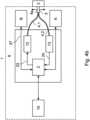
Die Messeinrichtung 6 ist mit der zweiten Strahlquelleneinrichtung B verbunden, mit der ein Lichtmuster MF auf der Haut des Probanden 3 ausgesendet wird. Die zweite Strahlquelleneinrichtung B sendet dazu Licht im sichtbaren Bereich derart auf den Probanden 3, dass das Lichtmuster MF ein Messfeld MF auf den Rücken des Probanden 3 projiziert. Das Messfeld MF weist eine Mehrzahl von Messorten Mi auf, die durch die von der zweiten Strahlquelleneinrichtung B ausgesendete Strahlung gleichzeitig optisch markiert sind.The measuring
Ein weiteres Ausführungsbeispiel des erfindungsgemäßen Schutzfaktor-Evaluierungssystems 1 zeigt
Die Durchführung erfolgt in vivo nach ISO 24442 bzw. 24444. Das Verfahren einer Messung zur Bestimmung eines Schutzfaktors eines Hautschutzmittels erfordert die Aufnahme von jeweils einem Remissionsspektrum der mit Schutzmittel unbehandelten Haut des Probanden 3 und der nach ISO 24442 oder 24444 in der Menge von 2.0mg/cm2 auf der zu prüfenden Hautoberfläche mit Schutzmittel behandelten Haut. Die Positionen der Messorte Mi mit und ohne Hautschutzmittel sollten nach dem Zufallsprinzip auf dem Rücken des Probanden 3 verteilt sein, um systematische Fehler aufgrund anatomischer Unterschiede der Haut zu verringern. Zwischen den Rändern benachbarter Messorte Mi sollte ein Mindestabstand von 1cm bestehen. Die Mindestfläche für einen Messort Mi beträgt nach ISO 24442 bzw. 24444 30cm2 und die Höchstfläche 60cm2.The test is carried out in vivo according to ISO 24442 or 24444. The measurement procedure for determining the protection factor of a skin protectant requires the recording of a reflectance spectrum of the skin of test subject 3 that is untreated with a protectant and of the skin treated with a protectant according to ISO 24442 or 24444 in an amount of 2.0 mg/cm2 on the skin surface to be tested. The positions of the measurement sites Mi with and without skin protectant should be randomly distributed on the back of test subject 3 in order to reduce systematic errors due to anatomical differences in the skin. There should be a minimum distance of 1 cm between the edges of adjacent measurement sites Mi . The minimum area for a measurement site Mi is 30 cm2 and the maximum area is 60 cm2 according to ISO 24442 or 24444.
Die Positionen der Messorte Mi sollten demnach mit einem Hautmarker und/oder einer Schablone aus nicht absorbierendem Material markiert und so gegenseitig abgegrenzt werden. Diese Abgrenzung wird erfindungsgemäß durch die zweite Strahlquelleneinrichtung B übernommen, die ein Lichtmuster MF auf den Rücken des Probanden 3 projiziert und damit ein Messfeld MF auf der Haut des Probanden 3 derart optisch markiert, dass eine Mehrzahl von Messorten Mi auf der Haut des Probanden 3 nach ISO 24442 bzw. 24444 gekennzeichnet ist.The positions of the measurement locations Mi should therefore be marked with a skin marker and/or a stencil made of non-absorbent material and thus delimited from one another. According to the invention, this delimitation is performed by the second beam source device B, which projects a light pattern MF onto the back of the subject 3 and thus optically marks a measurement field MF on the skin of the subject 3 in such a way that a plurality of measurement locations Mi on the skin of the subject 3 are marked according to ISO 24442 or 24444.
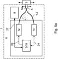
Mittels eines Lichtleiters 4.1 wird die von der ersten Strahlquelleneinrichtung 12 emittierte erste Strahlung mit einer Bestrahlungswellenlänge im Bereich zwischen 280nm und 500nm über den Probenkopf 5 und dem darin angeordneten Strahlauslass 5a in den Messkörper 3 eingeleitet. Das von dem Messkörper 3 reflektierte Licht gelangt über einen weiteren Lichtleiter 4.2 in die Detektionseinheit 13. Die Detektionseinheit 13 weist einen Monochromator, Filter, Photomultiplier, Spektrometer und/oder eine Photodiode auf. In diesem und allen folgenden Ausführungsbeispielen weist die Detektionseinheit 13 eine Photodiode auf. Detektionseinheit 13 und erste Strahlquelleneinrichtung 12 sind über Datenleitungen 23, 24 mit einer Steuereinheit 2 verbunden, die ihrerseits über eine weitere Datenleitung 25 mit der Auswerteeinheit 10 verbunden ist. Die Steuereinheit 2 ist üblicherweise ein PC oder Notebook-Computer mit geeignetem Computerprogramm, ebenso die Auswerteeinheit 10. Steuereinheit 2 und Detektionseinheit 13 sind ebenfalls über eine Datenleitung 24 miteinander verbunden. Die zweite Strahlquelleneinrichtung B ist mit der Steuereinheit 2 mittels der Datenleitung 27 verbunden (
Das von der LED 12.1 erzeugte Licht wird ungefiltert auf den ersten Messort M1 des Messkörpers 3 eingestrahlt, um ein hohes S / R-Verhältnis zu gewährleisten. Die Einstrahlung erfolgt mit einer Intensität, die keine akute Schädigung in der Haut verursacht, was unterhalb der einfachen MED, bzw. unterhalb der MZB-Werte, bzw. deutlich unterhalb den durch Sonneneinstrahlung verursachten Werten liegt. Das von dem ersten Messort M1 des Probanden 3 remittierte Licht wird durch den Lichtleiter 4.2 an Photodiode der Detektoreinheit 13 geleitet, von der Photodiode erfasst und in Messwerte umgewandelt, die Messwerte werden an die Steuereinheit 2 gesendet und in der Steuereinheit 2 gespeichert. Der erste Messort M1 wird von der Kamera K anvisiert, wobei in diesem und allen folgenden Ausführungsbeispielen alle Messorte Mi, die auf dem Rücken eines menschlichen Probanden 3 angeordnet sind, zeitgleich im Sichtfeld der Kamera K sind. Die Steuereinheit 2 weist eine Bilderkennungssoftware auf, mit der der erste Messort M1 überwacht und identifiziert wird.The light generated by the LED 12.1 is irradiated unfiltered onto the first measurement locationM1 of the measuring
In diesem Ausführungsbeispiel ist das Schutzfaktor-Evaluierungssystems 1 und der Probenkopf 5 fest angeordnet, während der Proband 3 beweglich angeordnet ist. Zur Aufnahme des Remissionsspektrums des zweiten Messortes M2 wird der zweite Messort M2 von der Kamera anvisiert und durch die Bilderkennungssoftware der Steuereinheit 2 identifiziert. Der Proband 3 wird dann derart bewegt, dass das durch den Probenkopf 5 und damit durch den Strahlauslass 5a von der LED 12.1 erzeugte Licht auf den zweiten Messort M2 eingestrahlt wird, wobei die Intensität der erzeugten Strahlung mit der bei der Aufnahme des ersten Messortes M1 übereinstimmt. Das von dem zweiten Messort M2 des Probanden 3 remittierte Licht wird durch den Lichtleiter 4.2 an Photodiode der Detektionseinheit 13 geleitet, von der Photodiode der Detektionseinheit 13 erfasst und in Messwerte umgewandelt, die Messwerte werden an die Steuereinheit 2 gesendet und in der Steuereinheit 2 gespeichert. In gleicher Weise wird jeweils ein Remissionsspektrum eines jeden Messortes Mi erfasst und in der Steuereinheit 2 separat gespeichert.In this embodiment, the protection
Die von der zweiten Strahlquelleneinrichtung B ausgesandte zweite Strahlung weist eine Wellenlänge von minimal 600nm auf, liegt also im sichtbaren roten Spektralbereich. Die Intensität der zweiten Strahlung ist derart gering unterhalb der Sonnenintensität, dass das Messfeld MF deutlich auf dem Rücken des Probanden 3 sichtbar ist, aber keine Hautschäden verursacht. Die von der zweiten Strahlquelleneinrichtung B zur Projizierung des Messfeldes MF ausgesandte zweite Strahlung ist durch die Steuereinheit 2 derart steuerbar, dass die Lage, Ausdehnung des Messfeldes MF und die Anzahl der einzelnen Messorte Mi individuell auf die anatomischen Gegebenheiten des Probanden 3 einstellbar ist. Diese einstellbaren Parameter sind ebenfalls für jeden Probanden 3 individuell in der Steuereinheit 2 speicherbar und können für z.B. Wiederholungsmessungen wieder abgerufen werden. Mittels der Kamera K wird die Auftreffposition der von der zweiten Strahlquelleneinrichtung B ausgesandten zweiten Strahlung auf dem Probanden 3 überwacht und identifiziert und mit der gespeicherten Zielposition verglichen. Bei Übereinstimmung der überwachten Auftreffposition der von der zweiten Strahlquelleneinrichtung B ausgesandten zweiten Strahlung mit der Zielposition gibt die mit der Steuereinheit 2 gekoppelte Ausgabeeinheit 14 ein akustisches Signal aus.The second radiation emitted by the second beam source device B has a wavelength of at least 600 nm, i.e., it lies in the visible red spectral range. The intensity of the second radiation is so slightly below the intensity of the sun that the measuring field MF is clearly visible on the back of the
Die Applikation des Hautschutzmittels und die anschließende zweite Messung wird an derselben Stelle der Messprobe 3, insbesondere auf derselben Stelle der Haut eines Probanden 3, durchgeführt, um die Reproduzierbarkeit der ersten und der zweiten Messung zu gewährleisten. Dazu wird das Hautschutzmittel zunächst auf den ersten Messort M1 appliziert. Ebenfalls zur Gewährleistung der Reproduzierbarkeit steuert die Steuereinheit 2 die LED 12.1 derart, dass das von der LED 12.1 erzeugte Licht durch den Lichtleiter 4.1 auf den ersten Messort M1 des Probanden 3 geleitet wird, wobei Intensität und Belichtungszeit von erster und zweiter Messung übereinstimmen. Mittels der Kamera K und der auf der Steuereinheit 2 gespeicherten Bilderkennungssoftware wird der erste Messort M1 identifiziert, und der Proband 3 wird derart bewegt, dass das durch den Probenkopf 5 und damit durch den Strahlauslass 5a von der LED 12.1 erzeugte Licht auf den ersten Messort M1 eingestrahlt wird. Während der Bewegung des Probanden 3 wird der erste Messort M1 durch die Kamera K überwacht.The application of the skin protection agent and the subsequent second measurement are carried out at the same location on the
Zur Überwachung der Position des ersten Messortes M1 können eine oder mehrere Referenzmarken am oder in der Nähe des Probanden 3 fest angeordnet sein. Durch die Referenzmarke wird eine Invarianz des Probanden 3 gegenüber Lage, Drehung und Größe erreicht, die Position des Probanden 3 also absolut erfasst. Die Referenzmarke kann ein Muster aufweisen, das durch die Steuereinheit 2 und die darauf gespeicherte Bilderkennungssoftware erkannt und identifizierbar ist. Die Referenzmarke kann alternativ oder zusätzlich retroreflektierend ausgeführt sein, wobei dann in unmittelbarer Nähe der Kamera K eine Beleuchtungseinrichtung angeordnet sein kann, z.B. ein durch die Steuereinheit 2 steuerbares Ringlicht um das Objektiv der Kamera K.To monitor the position of the first measurement location M1, one or more reference marks can be fixedly arranged on or near the
Bei Erreichen der korrekten Position des Probanden 3 gibt die mit der Steuereinheit 2 gekoppelte Ausgabeeinheit 14 ebenfalls ein akustisches Signal. Das Remissionsspektrum des ersten Messortes M1 wird in der Steuereinheit 2 gespeichert.When the correct position of the subject 3 is reached, the output unit 14 coupled to the
Zur Aufnahme des Remissionsspektrums des mit Hautschutzmittel applizierten zweiten Messortes M2 wird das Hautschutzmittel auf den zweiten Messort M2 appliziert, der zweite Messort M2 von der Kamera anvisiert und durch die Bilderkennungssoftware der Steuereinheit 2 identifiziert. Der Proband 3 wird anschließend derart bewegt, dass das durch den Probenkopf 5 und damit durch den Strahlauslass 5a von der LED 12.1 erzeugte Licht auf den zweiten Messort M2 eingestrahlt wird. Bei Erreichen der korrekten Position des Probanden 3 gibt die mit der Steuereinheit 2 gekoppelte Ausgabeeinheit 14 ebenfalls ein akustisches Signal. Das Remissionsspektrum des zweiten Messortes M2 wird in der Steuereinheit 2 gespeichert. Auf diese Weise wird jeweils ein Remissionsspektren eines jeden mit Hautschutzmittel applizierten Messortes Mi erfasst und in der Steuereinheit 2 separat gespeichert.To record the remission spectrum of the second measurement location M2 applied with skin protection agent, the skin protection agent is applied to the second measurement location M2 , the second measurement location M2 is targeted by the camera and identified by the image recognition software of the
Mittels der Kamera K und der auf der Steuereinheit 2 gespeicherten Bilderkennungssoftware wird ebenfalls die Auftreffposition der von der zweiten Strahlquelleneinrichtung B ausgesandten zweiten Strahlung auf dem Probanden 3 derart überwacht, identifiziert und mit der gespeicherten Zielposition verglichen, dass bei der Bewegung des Probanden 3 das Messfeld MF und damit die Messorte Mi relativ zum Probanden 3 jederzeit eine konstante Position einnimmt, die Messorte Mi also auf dem Probanden 3 jederzeit gleich verortet sind.By means of the camera K and the image recognition software stored on the
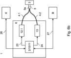
Ein weiteres Ausführungsbeispiel des erfindungsgemäßen Schutzfaktor-Evaluierungssystems 1 zeigt
Zur Aufnahme von Remissionsspektren der mit Schutzmittel unbehandelten Haut wird auf den ersten Messort M1 das durch den Probenkopf 5 und damit durch den Strahlauslass 5a von der LED 12.1 erzeugte Licht aufgebracht, das von dem ersten Messort M1 des Probanden 3 remittierte Licht wird durch den Lichtleiter 4.2 an Photodiode der Detektionseinheit 13 geleitet und in der Steuereinheit 2 gespeichert. Zur Aufnahme des Remissionsspektrums des zweiten Messortes M2 wird der zweite Messort M2 von der Kamera anvisiert und durch die Bilderkennungssoftware der Steuereinheit 2 identifiziert. Die Steuereinheit 2 steuert den Probenkopf 5 mit dem Strahlauslass 5a dann derart, dass das durch den Probenkopf 5 und damit durch den Strahlauslass 5a von der LED 12.1 erzeugte Licht auf den zweiten Messort M2 eingestrahlt wird.To record reflectance spectra of skin untreated with protective agent, the light generated by the
Zur Aufnahme von Remissionsspektren der mit Schutzmittel behandelten Haut wird auf den ersten Messort M1 das durch den Strahlauslass 5a von der LED 12.1 erzeugte Licht aufgebracht, das von dem ersten Messort M1 des Probanden 3 remittierte Licht wird durch den Lichtleiter 4.2 an Photodiode der Detektoreinheit 13 geleitet und in der Steuereinheit 2 gespeichert. Zur Aufnahme des Remissionsspektrums des zweiten Messortes M2 wird der zweite Messort M2 von der Kamera anvisiert und durch die Bilderkennungssoftware der Steuereinheit 2 identifiziert. Die Steuereinheit 2 steuert den Probenkopf 5 mit dem Strahlauslass 5a dann derart, dass das durch den Probenkopf 5 und damit durch den Strahlauslass 5a von der LED 12.1 erzeugte Licht auf den zweiten Messort M2 eingestrahlt wird. Bei Erreichen der korrekten Position des Probenkopfes 5 gibt die mit der Steuereinheit 2 gekoppelte Ausgabeeinheit 14 ein akustisches Signal.To record reflectance spectra of the skin treated with protective agent, the light generated by the
Zur Aufnahme von Remissionsspektren der mit Schutzmittel unbehandelten Haut wird auf den ersten Messort M1 das durch den Probenkopf 5 und damit durch den Strahlauslass 5a von der LED 12.1 erzeugte Licht aufgebracht, das von dem ersten Messort M1 des Probanden 3 remittierte Licht wird durch den Lichtleiter 4.2 an Photodiode der Detektionseinheit 13 geleitet und in der Steuereinheit 2 gespeichert. Zur Aufnahme des Remissionsspektrums des zweiten Messortes M2 wird der zweite Messort M2 von der Kamera anvisiert und durch die Bilderkennungssoftware der Steuereinheit 2 identifiziert. Die Steuereinheit 2 steuert den Probenkopf 5 mit dem Strahlauslass 5a und den Probanden 3 derart, dass das durch den Probenkopf 5 und damit durch den Strahlauslass 5a von der LED 12.1 erzeugte Licht auf den zweiten Messort M2 eingestrahlt wird.To record reflectance spectra of skin untreated with protective agent, the light generated by the
Zur Aufnahme von Remissionsspektren der mit Schutzmittel behandelten Haut wird auf den ersten Messort M1 das durch den Strahlauslass 5a von der LED 12.1 erzeugte Licht aufgebracht, das von dem ersten Messort M1 des Probanden 3 remittierte Licht wird durch den Lichtleiter 4.2 an Photodiode der Detektoreinheit 13 geleitet und in der Steuereinheit 2 gespeichert. Zur Aufnahme des Remissionsspektrums des zweiten Messortes M2 wird der zweite Messort M2 von der Kamera anvisiert und durch die Bilderkennungssoftware der Steuereinheit 2 identifiziert. Die Steuereinheit 2 steuert den Probenkopf 5 mit dem Strahlauslass 5a und den Probanden 3 dann derart, dass das durch den Probenkopf 5 und damit durch den Strahlauslass 5a von der LED 12.1 erzeugte Licht auf den zweiten Messort M2 eingestrahlt wird. Bei Erreichen der korrekten Position des Probenkopfes 5 gibt die mit der Steuereinheit 2 gekoppelte Ausgabeeinheit 14 ein akustisches Signal. Die Ausgabeeinheit 14 kann neben einem akustischen Signal auch ein optisches und/oder elektrisches Signal ausgeben. Bevorzugt ist die Ausgabeeinheit 14 ein Lautsprecher und/oder ein mit der Steuereinheit 2 gekoppelter Bildschirm.To record reflectance spectra of the skin treated with protective agent, the light generated by the
Mittels der Kamera K und der auf der Steuereinheit 2 gespeicherten Bilderkennungssoftware wird die Auftreffposition der von der zweiten Strahlquelleneinrichtung B ausgesandten zweiten Strahlung auf dem Probanden 3 derart überwacht, identifiziert und mit der gespeicherten Zielposition verglichen, dass bei der Bewegung des Probanden 3 bzw. des Probenkopfes 5 das Messfeld MF und damit die Messorte Mi relativ zum Probanden 3 jederzeit eine konstante Position einnimmt, die Messorte Mi also auf dem Probanden 3 jederzeit gleich verortet sind.By means of the camera K and the image recognition software stored on the
BEZUGSZEICHENLISTELIST OF REFERENCE SYMBOLS
- 11
- Schutzfaktor-EvaluierungssystemProtection Factor Evaluation System
- 22
- SteuereinheitControl unit
- 33
- Probe/Messkörper/Haut eines ProbandenSample/measuring body/skin of a test person
- 4.1, 4.24.1, 4.2
- Lichtleiter/FaserbündelOptical fiber/fiber bundle
- 55
- ProbenkopfProbe head
- 5a5a
- Strahlauslassjet outlet
- 66
- Messeinrichtungmeasuring device
- 7.17.1
- Referenzmarke am MessobjektReference mark on the measuring object
- 7.27.2
- Referenzmarke in der Nähe des MessobjektsReference mark near the measuring object
- 1010
- AuswerteeinrichtungEvaluation device
- 1111
- StrahlquellensteuerungBeam source control
- 1212
- Erste StrahlquelleneinrichtungFirst beam source facility
- 12.112.1
- Erste StrahlquelleFirst beam source
- 1313
- DetektionseinheitDetection unit
- 1414
- AusgabeeinheitOutput unit
- BB
- Zweite Strahlquelle / BeleuchtungSecond beam source / illumination
- KK
- Kameracamera
- MiWed
- MessortMeasuring location
- MFMF
- Messfeldmeasuring field
- 2121
- Verbindung Strahlquellensteuerung - SteuereinheitConnection beam source control - control unit
- 2222
- Verbindung Detektionseinheit / Spektrometer - SteuereinheitConnection detection unit / spectrometer - control unit
- 2323
- Verbindung Steuereinheit - Erste StrahlquelleneinrichtungConnection control unit - first beam source device
- 2424
- Verbindung Steuereinheit - DetektionseinheitConnection control unit - detection unit
- 2525
- Verbindung Steuereinheit - AuswerteeinrichtungConnection control unit - evaluation device
- 2626
- Verbindung Steuereinheit - KameraConnection control unit - camera
- 2727
- Verbindung Steuereinheit - Zweite StrahlquelleneinrichtungConnection control unit - second beam source device
ZITATE ENTHALTEN IN DER BESCHREIBUNGQUOTES CONTAINED IN THE DESCRIPTION
Diese Liste der vom Anmelder aufgeführten Dokumente wurde automatisiert erzeugt und ist ausschließlich zur besseren Information des Lesers aufgenommen. Die Liste ist nicht Bestandteil der deutschen Patent- bzw. Gebrauchsmusteranmeldung. Das DPMA übernimmt keinerlei Haftung für etwaige Fehler oder Auslassungen.This list of documents submitted by the applicant was generated automatically and is included solely for the convenience of the reader. This list is not part of the German patent or utility model application. The DPMA assumes no liability for any errors or omissions.
Zitierte PatentliteraturCited patent literature
- DE 198 28 497 A1 [0004]DE 198 28 497 A1 [0004]
- DE 10 2004 020 644 A1 [0005]
DE 10 2004 020 644 A1 [0005] - DE 103 47 608 A1 [0018, 0019, 0039]DE 103 47 608 A1 [0018, 0019, 0039]
Zitierte Nicht-PatentliteraturCited non-patent literature
- COLI PA -15 European Cosmetic, Toiletry and Perfumery Association: Colipa SPF Test Method 94/289, 1994 [0002]COLI PA -15 European Cosmetic, Toiletry and Perfumery Association: Colipa SPF Test Method 94/289, 1994 [0002]
- European Commission, 20 Standardisation Mandate Assigned To CEN Concerning Methods For Testing Efficacy Of Sunscreen Products, M/389 EN, Brüssels, 12 July 2006 [0002]European Commission, 20 Standardization Mandate Assigned To CEN Concerning Methods For Testing Efficacy Of Sunscreen Products, M/389 EN, Brussels, 12 July 2006 [0002]
- ISO 24444:2010 „Cosmetics - Sun protection test methods - In vivo determination of the sun protection factor (SPF) [0013]ISO 24444:2010 “Cosmetics - Sun protection test methods - In vivo determination of the sun protection factor (SPF) [0013]
Claims (38)
Translated fromGermanPriority Applications (1)
| Application Number | Priority Date | Filing Date | Title |
|---|---|---|---|
| DE102023125292.5ADE102023125292A1 (en) | 2023-09-19 | 2023-09-19 | MEASURING SYSTEM AND MEASURING METHOD |
Applications Claiming Priority (1)
| Application Number | Priority Date | Filing Date | Title |
|---|---|---|---|
| DE102023125292.5ADE102023125292A1 (en) | 2023-09-19 | 2023-09-19 | MEASURING SYSTEM AND MEASURING METHOD |
Publications (1)
| Publication Number | Publication Date |
|---|---|
| DE102023125292A1true DE102023125292A1 (en) | 2025-03-20 |
Family
ID=94776576
Family Applications (1)
| Application Number | Title | Priority Date | Filing Date |
|---|---|---|---|
| DE102023125292.5APendingDE102023125292A1 (en) | 2023-09-19 | 2023-09-19 | MEASURING SYSTEM AND MEASURING METHOD |
Country Status (1)
| Country | Link |
|---|---|
| DE (1) | DE102023125292A1 (en) |
Citations (5)
| Publication number | Priority date | Publication date | Assignee | Title |
|---|---|---|---|---|
| DE19828497A1 (en) | 1998-06-26 | 1999-12-30 | Mbr Messtechnik Gmbh | Detecting skin-damaging solar radiation |
| DE10347608A1 (en) | 2003-10-09 | 2005-05-19 | Daimlerchrysler Ag | Reference mark for photogrammetry/metrophotography has elements for fixing the center of the mark and for variable encoding of data on a circle around the center of the mark |
| DE102004020644A1 (en) | 2004-04-22 | 2005-11-17 | Coty B.V. | Method for determining an integral sun protection factor which detects UVA and UVB radiation |
| US10324032B2 (en)* | 2015-09-25 | 2019-06-18 | Apple Inc. | Light-based shielding detection |
| US20200182698A1 (en)* | 2015-06-15 | 2020-06-11 | Seoul Viosys Co., Ltd. | Hyper-spectral image measurement device and calibration method therefor, photographing module and device for skin diagnosis, skin diagnosis method, and skin image processing method |
- 2023
- 2023-09-19DEDE102023125292.5Apatent/DE102023125292A1/enactivePending
Patent Citations (5)
| Publication number | Priority date | Publication date | Assignee | Title |
|---|---|---|---|---|
| DE19828497A1 (en) | 1998-06-26 | 1999-12-30 | Mbr Messtechnik Gmbh | Detecting skin-damaging solar radiation |
| DE10347608A1 (en) | 2003-10-09 | 2005-05-19 | Daimlerchrysler Ag | Reference mark for photogrammetry/metrophotography has elements for fixing the center of the mark and for variable encoding of data on a circle around the center of the mark |
| DE102004020644A1 (en) | 2004-04-22 | 2005-11-17 | Coty B.V. | Method for determining an integral sun protection factor which detects UVA and UVB radiation |
| US20200182698A1 (en)* | 2015-06-15 | 2020-06-11 | Seoul Viosys Co., Ltd. | Hyper-spectral image measurement device and calibration method therefor, photographing module and device for skin diagnosis, skin diagnosis method, and skin image processing method |
| US10324032B2 (en)* | 2015-09-25 | 2019-06-18 | Apple Inc. | Light-based shielding detection |
Non-Patent Citations (3)
| Title |
|---|
| COLI PA -15 European Cosmetic, Toiletry and Perfumery Association: Colipa SPF Test Method 94/289, 1994 |
| European Commission, 20 Standardisation Mandate Assigned To CEN Concerning Methods For Testing Efficacy Of Sunscreen Products, M/389 EN, Brüssels, 12 July 2006 |
| ISO 24444:2010 „Cosmetics - Sun protection test methods - In vivo determination of the sun protection factor (SPF) |
Similar Documents
| Publication | Publication Date | Title |
|---|---|---|
| DE4200741C2 (en) | Device for the detection of caries on teeth | |
| EP1155657B1 (en) | Apparatus and method for distinguishing cancerous tissue | |
| DE202014010558U1 (en) | Device for receiving a hyperspectral image | |
| DE10128717A1 (en) | Method for recognition of natural skin, based on the properties of visible and near visible light scattered from the skin surface, thus increasing the security of biometric fingerprint identification | |
| DE102007062367A1 (en) | Optical diagnosis apparatus for improving illumination uniformity, capable of illuminating an assigned individual area of a target skin part by using a plurality of light emitting diodes as phosphor excitation light sources | |
| DE102009019545B4 (en) | Method and device for performing an optical comparison between at least two patterns, preferably by comparing selectable sections | |
| DE102020103490A1 (en) | MEASURING SYSTEM AND MEASURING METHOD | |
| WO2022013296A1 (en) | Measuring system and measuring method | |
| DE2741732C2 (en) | Layering device for the production of transverse layer images | |
| DE3718202C1 (en) | Arrangement for measuring a condition value for organic tissue areas | |
| WO2008113461A1 (en) | Method and device for evaluating fluorescence image records | |
| WO2024110310A9 (en) | Measuring method for determining a protection factor, and protection factor evaluation system | |
| EP3741290B1 (en) | Device for generating images of skin lesions | |
| EP4372364A1 (en) | Device and method for determining a protection factor | |
| DE102023125292A1 (en) | MEASURING SYSTEM AND MEASURING METHOD | |
| DE10118472C1 (en) | Head coil for a magnetic resonance device | |
| DE102022132844A1 (en) | MEASURING SYSTEM AND MEASURING METHODS | |
| DE102022124831A1 (en) | MEASURING SYSTEM AND MEASURING METHODS | |
| DE102023102315A1 (en) | MEASURING SYSTEM AND MEASURING METHODS | |
| DE102023125291A1 (en) | MEASURING SYSTEM AND MEASURING METHOD | |
| DE19802781A1 (en) | Quick identification of valuable objects by digital image analysis | |
| DE102023107705A1 (en) | DEVICE AND METHOD FOR DETERMINING A PROTECTION FACTOR | |
| WO2024068791A1 (en) | Method for determining a protection factor of a skin protectant | |
| DE102018221906B4 (en) | System for the detection of a measuring point on a sample | |
| WO2004027402A1 (en) | Method for determining the state of the surface of the skin of a human or animal body and arrangement for carrying out said method |
Legal Events
| Date | Code | Title | Description |
|---|---|---|---|
| R163 | Identified publications notified |