DE102023122449A1 - Surgical pistol grip and surgical instrument with pistol grip - Google Patents
Surgical pistol grip and surgical instrument with pistol gripDownload PDFInfo
- Publication number
- DE102023122449A1 DE102023122449A1DE102023122449.2ADE102023122449ADE102023122449A1DE 102023122449 A1DE102023122449 A1DE 102023122449A1DE 102023122449 ADE102023122449 ADE 102023122449ADE 102023122449 A1DE102023122449 A1DE 102023122449A1
- Authority
- DE
- Germany
- Prior art keywords
- handle
- actuating lever
- instrument
- overload protection
- protection element
- Prior art date
- Legal status (The legal status is an assumption and is not a legal conclusion. Google has not performed a legal analysis and makes no representation as to the accuracy of the status listed.)
- Pending
Links
- 230000008878couplingEffects0.000claimsabstractdescription14
- 238000010168coupling processMethods0.000claimsabstractdescription14
- 238000005859coupling reactionMethods0.000claimsabstractdescription14
- 230000005540biological transmissionEffects0.000claimsdescription76
- 238000009413insulationMethods0.000description51
- ORQBXQOJMQIAOY-UHFFFAOYSA-NnobeliumChemical compound[No]ORQBXQOJMQIAOY-UHFFFAOYSA-N0.000description15
- 238000013461designMethods0.000description14
- 230000036316preloadEffects0.000description10
- 238000003780insertionMethods0.000description8
- 230000037431insertionEffects0.000description8
- 238000013519translationMethods0.000description7
- 230000007246mechanismEffects0.000description4
- 239000002184metalSubstances0.000description4
- 229910000831SteelInorganic materials0.000description3
- 230000015572biosynthetic processEffects0.000description3
- POIUWJQBRNEFGX-XAMSXPGMSA-NcathelicidinChemical compoundC([C@@H](C(=O)N[C@@H](CCCNC(N)=N)C(=O)N[C@@H](CCCCN)C(=O)N[C@@H](CO)C(=O)N[C@@H](CCCCN)C(=O)N[C@@H](CCC(O)=O)C(=O)N[C@@H](CCCCN)C(=O)N[C@@H]([C@@H](C)CC)C(=O)NCC(=O)N[C@@H](CCCCN)C(=O)N[C@@H](CCC(O)=O)C(=O)N[C@@H](CC=1C=CC=CC=1)C(=O)N[C@@H](CCCCN)C(=O)N[C@@H](CCCNC(N)=N)C(=O)N[C@@H]([C@@H](C)CC)C(=O)N[C@@H](C(C)C)C(=O)N[C@@H](CCC(N)=O)C(=O)N[C@@H](CCCNC(N)=N)C(=O)N[C@@H]([C@@H](C)CC)C(=O)N[C@@H](CCCCN)C(=O)N[C@@H](CC(O)=O)C(=O)N[C@@H](CC=1C=CC=CC=1)C(=O)N[C@@H](CC(C)C)C(=O)N[C@@H](CCCNC(N)=N)C(=O)N[C@@H](CC(N)=O)C(=O)N[C@@H](CC(C)C)C(=O)N[C@@H](C(C)C)C(=O)N1[C@@H](CCC1)C(=O)N[C@@H](CCCNC(N)=N)C(=O)N[C@@H]([C@@H](C)O)C(=O)N[C@@H](CCC(O)=O)C(=O)N[C@@H](CO)C(O)=O)NC(=O)[C@H](CC=1C=CC=CC=1)NC(=O)[C@H](CC(O)=O)NC(=O)CNC(=O)[C@H](CC(C)C)NC(=O)[C@@H](N)CC(C)C)C1=CC=CC=C1POIUWJQBRNEFGX-XAMSXPGMSA-N0.000description3
- 238000011161developmentMethods0.000description3
- 230000018109developmental processEffects0.000description3
- 238000006073displacement reactionMethods0.000description3
- 238000010292electrical insulationMethods0.000description3
- 239000010959steelSubstances0.000description3
- 230000008901benefitEffects0.000description2
- 210000003811fingerAnatomy0.000description2
- 235000019589hardnessNutrition0.000description2
- 238000009434installationMethods0.000description2
- 239000000463materialSubstances0.000description2
- 230000001954sterilising effectEffects0.000description2
- BUHVIAUBTBOHAG-FOYDDCNASA-N(2r,3r,4s,5r)-2-[6-[[2-(3,5-dimethoxyphenyl)-2-(2-methylphenyl)ethyl]amino]purin-9-yl]-5-(hydroxymethyl)oxolane-3,4-diolChemical compoundCOC1=CC(OC)=CC(C(CNC=2C=3N=CN(C=3N=CN=2)[C@H]2[C@@H]([C@H](O)[C@@H](CO)O2)O)C=2C(=CC=CC=2)C)=C1BUHVIAUBTBOHAG-FOYDDCNASA-N0.000description1
- 241000282693CercopithecidaeSpecies0.000description1
- 239000004696Poly ether ether ketoneSubstances0.000description1
- 230000004913activationEffects0.000description1
- JUPQTSLXMOCDHR-UHFFFAOYSA-Nbenzene-1,4-diol;bis(4-fluorophenyl)methanoneChemical compoundOC1=CC=C(O)C=C1.C1=CC(F)=CC=C1C(=O)C1=CC=C(F)C=C1JUPQTSLXMOCDHR-UHFFFAOYSA-N0.000description1
- 239000004020conductorSubstances0.000description1
- 238000010276constructionMethods0.000description1
- 238000001839endoscopyMethods0.000description1
- 238000002357laparoscopic surgeryMethods0.000description1
- 238000002324minimally invasive surgeryMethods0.000description1
- 239000004033plasticSubstances0.000description1
- 229920002530polyetherether ketonePolymers0.000description1
- 230000009467reductionEffects0.000description1
- 238000004659sterilization and disinfectionMethods0.000description1
- 230000008719thickeningEffects0.000description1
- 210000003813thumbAnatomy0.000description1
- 238000012546transferMethods0.000description1
Images


Classifications
- A—HUMAN NECESSITIES
- A61—MEDICAL OR VETERINARY SCIENCE; HYGIENE
- A61B—DIAGNOSIS; SURGERY; IDENTIFICATION
- A61B17/00—Surgical instruments, devices or methods
- A61B17/28—Surgical forceps
- A61B17/29—Forceps for use in minimally invasive surgery
- A61B17/2909—Handles
- A—HUMAN NECESSITIES
- A61—MEDICAL OR VETERINARY SCIENCE; HYGIENE
- A61B—DIAGNOSIS; SURGERY; IDENTIFICATION
- A61B18/00—Surgical instruments, devices or methods for transferring non-mechanical forms of energy to or from the body
- A61B18/04—Surgical instruments, devices or methods for transferring non-mechanical forms of energy to or from the body by heating
- A61B18/12—Surgical instruments, devices or methods for transferring non-mechanical forms of energy to or from the body by heating by passing a current through the tissue to be heated, e.g. high-frequency current
- A61B18/14—Probes or electrodes therefor
- A61B18/1442—Probes having pivoting end effectors, e.g. forceps
- A61B18/1445—Probes having pivoting end effectors, e.g. forceps at the distal end of a shaft, e.g. forceps or scissors at the end of a rigid rod
- A—HUMAN NECESSITIES
- A61—MEDICAL OR VETERINARY SCIENCE; HYGIENE
- A61B—DIAGNOSIS; SURGERY; IDENTIFICATION
- A61B90/00—Instruments, implements or accessories specially adapted for surgery or diagnosis and not covered by any of the groups A61B1/00 - A61B50/00, e.g. for luxation treatment or for protecting wound edges
- A61B90/03—Automatic limiting or abutting means, e.g. for safety
- A—HUMAN NECESSITIES
- A61—MEDICAL OR VETERINARY SCIENCE; HYGIENE
- A61B—DIAGNOSIS; SURGERY; IDENTIFICATION
- A61B17/00—Surgical instruments, devices or methods
- A61B2017/0046—Surgical instruments, devices or methods with a releasable handle; with handle and operating part separable
- A—HUMAN NECESSITIES
- A61—MEDICAL OR VETERINARY SCIENCE; HYGIENE
- A61B—DIAGNOSIS; SURGERY; IDENTIFICATION
- A61B17/00—Surgical instruments, devices or methods
- A61B17/28—Surgical forceps
- A61B17/29—Forceps for use in minimally invasive surgery
- A61B17/2909—Handles
- A61B2017/2912—Handles transmission of forces to actuating rod or piston
- A61B2017/2919—Handles transmission of forces to actuating rod or piston details of linkages or pivot points
- A61B2017/292—Handles transmission of forces to actuating rod or piston details of linkages or pivot points connection of actuating rod to handle, e.g. ball end in recess
- A—HUMAN NECESSITIES
- A61—MEDICAL OR VETERINARY SCIENCE; HYGIENE
- A61B—DIAGNOSIS; SURGERY; IDENTIFICATION
- A61B17/00—Surgical instruments, devices or methods
- A61B17/28—Surgical forceps
- A61B17/29—Forceps for use in minimally invasive surgery
- A61B17/2909—Handles
- A61B2017/2912—Handles transmission of forces to actuating rod or piston
- A61B2017/2923—Toothed members, e.g. rack and pinion
- A—HUMAN NECESSITIES
- A61—MEDICAL OR VETERINARY SCIENCE; HYGIENE
- A61B—DIAGNOSIS; SURGERY; IDENTIFICATION
- A61B17/00—Surgical instruments, devices or methods
- A61B17/28—Surgical forceps
- A61B17/29—Forceps for use in minimally invasive surgery
- A61B17/2909—Handles
- A61B2017/2925—Pistol grips
- A—HUMAN NECESSITIES
- A61—MEDICAL OR VETERINARY SCIENCE; HYGIENE
- A61B—DIAGNOSIS; SURGERY; IDENTIFICATION
- A61B17/00—Surgical instruments, devices or methods
- A61B17/28—Surgical forceps
- A61B17/29—Forceps for use in minimally invasive surgery
- A61B2017/2926—Details of heads or jaws
- A61B2017/2927—Details of heads or jaws the angular position of the head being adjustable with respect to the shaft
- A61B2017/2929—Details of heads or jaws the angular position of the head being adjustable with respect to the shaft with a head rotatable about the longitudinal axis of the shaft
- A—HUMAN NECESSITIES
- A61—MEDICAL OR VETERINARY SCIENCE; HYGIENE
- A61B—DIAGNOSIS; SURGERY; IDENTIFICATION
- A61B17/00—Surgical instruments, devices or methods
- A61B17/28—Surgical forceps
- A61B17/29—Forceps for use in minimally invasive surgery
- A61B2017/2926—Details of heads or jaws
- A61B2017/2932—Transmission of forces to jaw members
- A61B2017/2933—Transmission of forces to jaw members camming or guiding means
- A61B2017/2936—Pins in guiding slots
- A—HUMAN NECESSITIES
- A61—MEDICAL OR VETERINARY SCIENCE; HYGIENE
- A61B—DIAGNOSIS; SURGERY; IDENTIFICATION
- A61B17/00—Surgical instruments, devices or methods
- A61B17/28—Surgical forceps
- A61B17/29—Forceps for use in minimally invasive surgery
- A61B2017/2946—Locking means
- A—HUMAN NECESSITIES
- A61—MEDICAL OR VETERINARY SCIENCE; HYGIENE
- A61B—DIAGNOSIS; SURGERY; IDENTIFICATION
- A61B90/00—Instruments, implements or accessories specially adapted for surgery or diagnosis and not covered by any of the groups A61B1/00 - A61B50/00, e.g. for luxation treatment or for protecting wound edges
- A61B90/08—Accessories or related features not otherwise provided for
- A61B2090/0813—Accessories designed for easy sterilising, i.e. re-usable
Landscapes
- Health & Medical Sciences (AREA)
- Surgery (AREA)
- Life Sciences & Earth Sciences (AREA)
- Engineering & Computer Science (AREA)
- Veterinary Medicine (AREA)
- Molecular Biology (AREA)
- Nuclear Medicine, Radiotherapy & Molecular Imaging (AREA)
- Public Health (AREA)
- Biomedical Technology (AREA)
- Heart & Thoracic Surgery (AREA)
- Medical Informatics (AREA)
- General Health & Medical Sciences (AREA)
- Animal Behavior & Ethology (AREA)
- Otolaryngology (AREA)
- Plasma & Fusion (AREA)
- Physics & Mathematics (AREA)
- Oral & Maxillofacial Surgery (AREA)
- Pathology (AREA)
- Ophthalmology & Optometry (AREA)
- Surgical Instruments (AREA)
Abstract
Translated fromGermanDescription
Translated fromGermanTechnisches Gebiettechnical field
Die vorliegende Offenbarung betrifft einen chirurgischen Pistolen-Handgriff für ein chirurgisches Instrument oder eines chirurgischen Instruments, insbesondere elektrochirurgisches Instrument der minimalinvasiven Schaftbauart. Zudem betrifft die vorliegende Offenbarung ein chirurgisches Instrument mit einem solchen Pistolen-Handgriff.The present disclosure relates to a surgical pistol handle for a surgical instrument or a surgical instrument, in particular an electrosurgical instrument of the minimally invasive shaft design. In addition, the present disclosure relates to a surgical instrument with such a pistol handle.
Aus dem Stand der Technik sind bereits (elektro-)chirurgische Instrumente, insbesondere der minimalinvasiven Bauart, bekannt, die mittels eines insbesondere mehrteiligen, etwa aus zwei scheren-, klemmbacken-, zangen- oder pinzettenförmigen, gegeneinander/zueinander beweglichen, insbesondere verschwenkbaren Werkzeugbranchen/-elementen aufgebauten Werkzeugs ein Schneiden, Greifen, Halten und/oder Klemmen von Körpergewebe ermöglichen, um dieses durch Anlegen einer Hochfrequenzspannung monopolar oder bipolar zu koagulieren, zu veröden oder zu durchtrennen. Ein solches Instrument ist beispielsweise aus der
Dabei ist das Werkzeug an einem distalen (/operateurfernen bzw. patientennahen) Ende des Instruments, insbesondere an einem Instrumentenschaft des Instruments angelenkt (oder anlenkbar) und zu einer Betätigung (/Bedienung) des Werkzeugs über eine Transmission, vorzugsweise in Form einer im Inneren des Instrumentenschafts angeordneten, insbesondere längsverschieblichen Zug-/Druckstange, mit einem Handgriff an einem proximalen (/operateurnahen bzw. patientenfernen) Ende des Instruments gekoppelt. Der Handgriff weist ein der Betätigung des Werkzeugs entsprechendes Betätigungselement (etwa in Form eines Griff-/Abzughebels, einer Taste, eines Drehknopfs, eines Scherengriffs) auf, dessen (insbesondere manuelle) Betätigung/Aktuierung zu einer entsprechend umgesetzten Bewegung der Werkzeugbranchen am Einsatz-/Anwendungsort führt, wie etwa zu einer Schneide-/Greif-/Halte-/Klemmbewegung und/oder einer Dreh-/Schwenkbewegung am oder im Gewebe eines Patienten.The tool is articulated (or articulateable) at a distal end of the instrument (far from the operator or near the patient), in particular at an instrument shaft of the instrument, and is coupled to a handle at a proximal end of the instrument (near the operator or far from the patient) for actuation (operation) of the tool via a transmission, preferably in the form of a pull/push rod arranged inside the instrument shaft, in particular a longitudinally displaceable rod. The handle has an actuating element corresponding to the actuation of the tool (for example in the form of a handle/trigger lever, a button, a rotary knob, a scissor handle), the (in particular manual) actuation/activation of which leads to a correspondingly implemented movement of the tool branches at the place of use/application, such as a cutting/gripping/holding/clamping movement and/or a rotating/pivoting movement on or in the tissue of a patient.
Elektrochirurgische Instrumente der einschlägigen Bauart verwenden in der Regel einen sogenannten Pistolen-Handgriff mit einer starren/unbeweglichen Griffschale, insbesondere in Form eines (Getriebe-)Gehäuse, das sich von distal in Richtung proximal, d.h. im Wesentlichen entlang einer Schaftachse des Instrumentenschafts, erstreckt, und eines feststehenden Griffelements, das sich in einem Winkel/quer zur distal-proximal Richtung erstreckt und an einem proximalen Endabschnitt des (Getriebe-)Gehäuses (integral/unmittelbar) an diesem ausgebildet oder (als separates, fest damit verbundenes Bauteil) daran fixiert ist. An der Griffschale ist ein insbesondere manuell betätigbarer, vorzugsweise fingerführbarer oder fingergeführter Betätigungshebel (/Abzugsbügel/-züngel) schwenkbar angelenkt, der - beispielsweise im Affengriff - durch mehrere Finger einer Greifhand eines Operateurs/Bedieners gehalten und zum Betätigen hin zur Griffschale, insbesondere zum Griffelement, manuell gezogen werden kann. Diese Zieh-/Betätigungsbewegung des Betätigungshebels/Abzugsbügels wird über ein im (Getriebe-)Gehäuse untergebrachtes Getriebe auf die Transmission innerhalb des an den Handgriff angekuppelten oder ankuppelbaren Instrumentenschafts auf das Werkzeug das Instrument übertragen, um dieses entsprechend zu bewegen/betätigen. Außerdem ist an dem Pistolen-Handgriff vorzugsweise eine Art Schalter angebracht, mittels dem das Anlegen der Hochfrequenzspannung an dem Werkzeug ausgelöst werden kann.Electrosurgical instruments of the relevant design generally use a so-called pistol handle with a rigid/immovable handle shell, in particular in the form of a (gear) housing that extends from distal to proximal, i.e. essentially along a shaft axis of the instrument shaft, and a fixed handle element that extends at an angle/transversely to the distal-proximal direction and is formed (integrally/directly) on a proximal end section of the (gear) housing or is fixed to it (as a separate, firmly connected component). An actuating lever (/trigger/blade), in particular manually operable, preferably finger-guided or finger-guided, is pivotally connected to the handle shell, which - for example in a monkey grip - can be held by several fingers of a gripping hand of a surgeon/operator and can be manually pulled towards the handle shell, in particular the handle element, for actuation. This pulling/actuating movement of the actuating lever/trigger guard is transmitted to the tool via a gear housed in the (gear) housing via the transmission within the instrument shaft, which is coupled or can be coupled to the handle, in order to move/actuate it accordingly. In addition, a type of switch is preferably attached to the pistol handle, by means of which the high-frequency voltage can be applied to the tool.
Wenigstens eine der beiden Werkzeugbranchen kann mit einer Elektrode oder Elektrodenreihe ausgestattet sein, über welche die Hochfrequenzspannung in das ergriffene Patientengewebe wahlweise eingeleitet werden kann. In diesem Fall läge ein elektrochirurgisches Instrument der monopolaren Bauart vor, bei der ein Patient beispielsweise auf einer Metallplatte aufliegt, über die der Hochfrequenzspannung abgeleitet wird. Alternativ hierzu können aber auch beide, sich gegenüberliegenden Werkzeugbranchen mit einer entsprechenden Elektrode oder Elektrodenreihe ausgestattet sein oder aus einem elektrisch leitfähigen Material bestehen, so dass die Hochfrequenzspannung nur in einem Spalt zwischen den Branchen anliegt. In diesem Fall läge dann ein elektrochirurgisches Instrument der bipolaren Bauart vor.At least one of the two tool branches can be equipped with an electrode or row of electrodes, via which the high-frequency voltage can be selectively introduced into the patient's tissue. In this case, this would be a monopolar electrosurgical instrument, in which a patient lies on a metal plate, for example, via which the high-frequency voltage is discharged. Alternatively, both opposing tool branches can be equipped with a corresponding electrode or row of electrodes or can be made of an electrically conductive material, so that the high-frequency voltage is only present in a gap between the branches. In this case, this would be a bipolar electrosurgical instrument.
Bei bekannten Pistolen-Handgriffen ist es aufgrund der Bauform möglich, sehr hohe Betätigungskräfte über den Betätigungshebel aufzubringen. Insbesondere, wenn dabei zwischen den Werkzeugbranchen Gewebe oder dergleichen eingeklemmt/gegriffen ist, wird eine Schwenkbewegung des Betätigungshebels (vor einer möglichen Endstellung) begrenzt, wodurch bei einem weiteren Aufbringen einer Betätigungskraft oder einem Erhöhen der Betätigungskraft die im Kraftübertragungszug angeordneten Komponenten des Instruments beschädigt werden könnten, was unbedingt zu vermeiden ist.Due to their design, it is possible to apply very high actuation forces via the actuation lever on known pistol handles. In particular, if tissue or similar is clamped/gripped between the tool jaws, a pivoting movement of the actuation lever (before a possible end position) is limited, which means that if an additional actuation force is applied or the actuation force is increased, the components of the instrument arranged in the force transmission cable could be damaged, which must be avoided at all costs.
Es ist also die Aufgabe der vorliegenden Offenbarung, die Nachteile aus dem Stand der Technik zu vermeiden oder wenigstens zu verringern. Insbesondere soll ein Pistolen-Handgriff eines oder für ein chirurgisches Instrument sowie ein chirurgisches Instrument mit einem solchen Pistolen-Handgriff bereitgestellt werden, der/das besonders ergonomisch zu bedienen ist sowie bauraumsparend aufgebaut ist, und gleichzeitig eine geeignete Kraftübertragung von dem Handgriff auf das Werkzeug ermöglicht und die in der Kraftübertragung beteiligten Komponenten dabei vor Überbelastung und dadurch entstehender Beschädigung schützt.It is therefore the object of the present disclosure to avoid or at least reduce the disadvantages of the prior art. In particular, a pistol handle of or for a surgical instrument and a surgical instrument with such a pistol handle which is particularly ergonomic to use and has a space-saving design, while at the same time enabling suitable power transmission from the handle to the tool and protecting the components involved in the power transmission from overloading and the resulting damage.
Diese Aufgabe wird gelöst durch einen chirurgischen Pistolen-Handgriff eines oder für ein chirurgisches Instrument, insbesondere elektrochirurgisches Instrument mit den Merkmalen des unabhängigen Patentanspruchs und/oder durch ein chirurgisches Instrument, insbesondere elektrochirurgisches Instrument mit den Merkmalen des nebengeordneten Patentanspruchs. Vorteilhafte Ausgestaltungen und Weiterbildungen gemäß der Offenbarung sind Gegenstand der Unteransprüche.This object is achieved by a surgical pistol handle of or for a surgical instrument, in particular an electrosurgical instrument with the features of the independent patent claim and/or by a surgical instrument, in particular an electrosurgical instrument with the features of the independent patent claim. Advantageous embodiments and further developments according to the disclosure are the subject of the subclaims.
Demnach wird die Aufgabe durch einen chirurgischen Pistolen-Handgriff (nachfolgend auch lediglich als Handgriff bezeichnet) eines oder für ein chirurgisches Instrument, insbesondere elektrochirurgisches Instrument der minimalinvasiven Schaftbauart gelöst. Der Handgriff weist ein Getriebegehäuse auf, das sich von distal in Richtung proximal (/in einer distal-proximal-Richtung, die im Wesentlichen einer Richtung entlang einer Schaftachse eines an den Handgriff angekoppelten oder ankoppelbaren Instrumentenschafts bzw. einer Schaftbaugruppe entspricht) erstreckt. Zudem weist der Handgriff ein feststehendes Griffelement (/Griffteil) auf, das sich in einem Winkel, d.h. quer, zur distal-proximal-Richtung, erstreckt und an einem proximalen Endabschnitt des Getriebegehäuses (fest daran) fixiert ist oder insbesondere an dem Getriebegehäuse ausgebildet ist, d.h. integral mit dem Getriebegehäuse ausgebildet/verbunden ist. Ferner weist der Handgriff einen an dem Getriebegehäuse schwenkbar angelenkten, insbesondere manuell betätigbaren, vorzugsweise fingerführbaren Betätigungshebel (/Abzugshebel) auf, durch den eine Betätigungskraft (durch den Operateur) aufgebracht werden kann. Weiter weist der Handgriff ein im Getriebegehäuse untergebrachtes/aufgenommenes Getriebe auf, das ausgebildet ist, um eine (durch die manuelle Betätigung hervorgerufene) Schwenkbewegung des Betätigungshebels in eine Translationsbewegung, vorzugsweise Längsbewegung einer Transmission, vorzugsweise einer innerhalb eines an den Pistolen-Handgriff distal angekuppelten/angekoppelten oder ankuppelbaren/ankoppelbaren Instrumentenschafts gelagerten Zug-/Druckstange zu übertragen. Dabei weist das Getriebe ein an dem Getriebegehäuse angelenktes (erstes) Drehteil und ein die Schwenkbewegung des Betätigungshebels mit einer Rotation des (ersten) Drehteils koppelndes, elastisches Überlastsicherungselement auf. Das heißt, dass das Überlastsicherungselement im Kraftübertragungszug/Kraftfluss zwischen dem Betätigungshebel und dem Drehteil angeordnet ist. Dies hat den Vorteil, dass eine am Betätigungshebel aufgebrachte Überlast (direkt nach dem Einleiten) abgefedert werden kann, so dass alle im Kraftübertragungszug dahinter angeordneten Bauteile vor Überlast geschützt werden.Accordingly, the task is solved by a surgical pistol handle (hereinafter also referred to simply as handle) of or for a surgical instrument, in particular an electrosurgical instrument of the minimally invasive shaft design. The handle has a gear housing that extends from distal to proximal (/in a distal-proximal direction that essentially corresponds to a direction along a shaft axis of an instrument shaft or shaft assembly that is or can be coupled to the handle). In addition, the handle has a fixed handle element (/handle part) that extends at an angle, i.e. transversely, to the distal-proximal direction and is fixed to a proximal end section of the gear housing (firmly thereto) or in particular is formed on the gear housing, i.e. is formed/connected integrally to the gear housing. The handle also has an actuating lever (/trigger) which is pivotally connected to the gear housing, in particular can be operated manually and is preferably finger-operable, and by means of which an actuating force can be applied (by the surgeon). The handle also has a gear housed in the gear housing, which is designed to convert a pivoting movement of the actuating lever (caused by manual actuation) into a translational movement, preferably a longitudinal movement of a transmission, preferably a pull/push rod mounted within an instrument shaft which is distally coupled or can be coupled to the pistol handle. The gear has a (first) rotating part which is pivoted to the gear housing and an elastic overload protection element which couples the pivoting movement of the actuating lever to a rotation of the (first) rotating part. This means that the overload protection element is arranged in the force transmission line/force flow between the actuating lever and the rotating part. This has the advantage that an overload applied to the actuating lever (immediately after it is introduced) can be cushioned so that all components arranged behind it in the power transmission train are protected against overload.
Ein Kern der vorliegenden Offenbarung besteht folglich darin, dass in dem Handgriff ein Überlastsicherungselement eingebaut ist, welches eine zu hohe auf den Betätigungshebel aufgebrachte Betätigungskraft abfedert, so dass diese nicht auf das Getriebe und die im Kraftübertragungszug angeordneten Komponenten übertragen wird.A core of the present disclosure is therefore that an overload protection element is built into the handle, which cushions an excessive actuating force applied to the actuating lever so that it is not transmitted to the gear box and the components arranged in the power transmission train.
Gemäß einer bevorzugten Ausführungsform können der Betätigungshebel und das Drehteil um dieselbe Achse (drehbar bzw. schwenkbar) an dem Getriebegehäuse angelenkt sein. Dadurch wird ein besonders einfacher Aufbau ermöglicht und eine gute Kraftübertragung über das Überlastsicherungselement im „normalen“ Lastbereich (d.h. nicht im Überlastbereich) sichergestellt.According to a preferred embodiment, the actuating lever and the rotating part can be hinged to the gear housing about the same axis (rotatable or pivotable). This enables a particularly simple construction and ensures good power transmission via the overload protection element in the "normal" load range (i.e. not in the overload range).
Gemäß einer bevorzugten Ausführungsform kann das Überlastsicherungselement als ein Federelement, insbesondere als eine Schraubenfeder, ausgebildet sein. Dadurch ist das Überlastsicherungselement einfach und kostengünstig. Zudem kann die Dimensionierung der Überlastsicherung durch Wahl einer entsprechenden Schraubenfeder eingestellt werden.According to a preferred embodiment, the overload protection element can be designed as a spring element, in particular as a helical spring. This makes the overload protection element simple and cost-effective. In addition, the dimensioning of the overload protection can be adjusted by selecting an appropriate helical spring.
Gemäß einer bevorzugten Ausführungsform kann der Betätigungshebel eine Ausnehmung aufweisen, in der das Überlastsicherungselement aufgenommen ist. Das heißt, dass das Überlastsicherungselement bauraumtechnisch direkt in dem Betätigungshebel integriert ist, so dass der Handgriff trotz zusätzlichem Überlastsicherungselement bauraumsparend ist.According to a preferred embodiment, the actuating lever can have a recess in which the overload protection element is accommodated. This means that the overload protection element is integrated directly into the actuating lever in terms of installation space, so that the handle saves installation space despite the additional overload protection element.
Gemäß einer Weiterbildung der bevorzugten Ausführungsform kann das Überlastsicherungselement vollständig innerhalb der Ausnehmung des Betätigungshebels angeordnet ist, wobei das Überlastsicherungselement vorzugsweise nach außen hin durch den Betätigungshebel abgedeckt ist. Dadurch kann das Überlastsicherungselement vor Kontakt mit der Umgebung geschützt werden, was Vorteile hinsichtlich Sterilisation hat.According to a further development of the preferred embodiment, the overload protection element can be arranged completely within the recess of the actuating lever, wherein the overload protection element is preferably covered on the outside by the actuating lever. The overload protection element can thus be protected from contact with the environment, which has advantages in terms of sterilization.
Gemäß einer Weiterbildung der bevorzugten Ausführungsform kann das Überlastsicherungselement lose, d.h. nicht fest verbunden mit dem Betätigungshebel und/oder dem Drehteil) in der Ausnehmung aufgenommen sein. Das heißt, dass die Enden des Überlastsicherungselement lediglich an dem Betätigungshebel bzw. Drehteil anliegen und nur Druckkräfte übertragen werden können.According to a further development of the preferred embodiment, the overload protection element can be accommodated in the recess loosely, i.e. not firmly connected to the actuating lever and/or the rotating part. This means that the ends of the overload protection element only rest on the actuating lever or the rotating part and only pressure forces can be transmitted.
Gemäß einer bevorzugten Ausführungsform kann der Betätigungshebel, etwa durch Zusammendrücken von Betätigungshebel und Griffelement, in eine Betätigungsrichtung zum Griffelement hin (und, etwa durch Auseinanderdrücken von Betätigungshebel und Griffelement in eine Rückstellrichtung vom Griffelement weg) verschwenkbar sein. Dabei kann das Überlastsicherungselement insbesondere so angeordnet sein, dass es in der Betätigungsrichtung wirkt. Vorzugsweise kann das Überlastsicherungselement so angeordnet sein, dass es (nur/ausschließlich) in der Betätigungsrichtung (und nicht in der Rückstellrichtung) wirkt. Das heißt, dass das Überlastsicherungselement nur die Schwenkbewegung des Betätigungshebels zum Griffelement hin begrenzt/dämpft/vor Überlast sichert/schützt. Insbesondere können eine Betätigungsübertragungsfläche des Betätigungshebels und eine Rückstellübertragungsfläche des Betätigungshebels voneinander getrennt, d.h. an unterschiedlichen Flächen, ausgebildet sein. Das heißt, dass der Betätigungshebel und das erste Drehteil nicht fest miteinander verbunden sind, und eine (rein drückende) Kraftübertragung bei dem Betätigen des Betätigungshebels über die über das Überlastsicherungselement mit dem ersten Drehteil gekoppelte Betätigungsübertragungsfläche und eine (rein drückende) Kraftübertragung bei dem Rückstellen des Betätigungshebels (direkt) über die an dem ersten Drehteil anliegende gekoppelte Rückstellübertragungsfläche erfolgt.According to a preferred embodiment, the actuating lever can be pivoted in an actuating direction towards the handle element (and, for example, by pushing the actuating lever and handle element apart in a return direction away from the handle element), for example by pressing the actuating lever and handle element together. The overload protection element can in particular be arranged so that it acts in the actuating direction. Preferably, the overload protection element can be arranged so that it acts (only/exclusively) in the actuating direction (and not in the return direction). This means that the overload protection element only limits/damps/secures/protects against overload the pivoting movement of the actuating lever towards the handle element. In particular, an actuating transmission surface of the actuating lever and a return transmission surface of the actuating lever can be formed separately from one another, i.e. on different surfaces. This means that the actuating lever and the first rotating part are not firmly connected to one another, and a (purely pressing) force transmission when the actuating lever is actuated takes place via the actuating transmission surface coupled to the first rotating part via the overload protection element and a (purely pressing) force transmission when the actuating lever is returned takes place (directly) via the coupled return transmission surface adjacent to the first rotating part.
Gemäß einer bevorzugten Ausführungsform kann das Überlastsicherungselement so angeordnet und dimensioniert sein, dass eine anfängliche Kraftübertragung (anfänglich im Sinne der Betätigung, d.h. ausgehend von der Schwenkbewegung aus einer unbetätigten Stellung des Betätigungshebels hin zum Griffelement) über das Überlastsicherungselement zwischen dem Betätigungshebel und dem Drehteil ein im Wesentlichen lineares Übertragungsverhalten aufweist. Das heißt, dass die Kopplung über das Überlastsicherungselement bei der anfänglichen Kraftübertragung, insbesondere bei Kraftübertragung innerhalb des „normalen“ Lastbereich/Arbeitsbereichs (und ohne Widerstand am Werkzeug), quasi starr/unelastisch ist. Das heißt, dass das Überlastsicherungselement eine ausreichend hohe Steifigkeit/Härte aufweist, um die Kraftübertragung im „normalen“ Lastbereich nicht oder nur kaum zu beeinflussen.According to a preferred embodiment, the overload protection element can be arranged and dimensioned such that an initial force transmission (initially in the sense of actuation, i.e. starting from the pivoting movement from an unactuated position of the actuating lever to the handle element) via the overload protection element between the actuating lever and the rotating part has a substantially linear transmission behavior. This means that the coupling via the overload protection element is quasi rigid/inelastic during the initial force transmission, in particular during force transmission within the "normal" load range/working range (and without resistance on the tool). This means that the overload protection element has a sufficiently high rigidity/hardness to have little or no influence on the force transmission in the "normal" load range.
Gemäß einer bevorzugten Ausführungsform kann das Überlastsicherungselement so angeordnet und dimensioniert sein, dass das Überlastsicherungselement erst ab einer über den Betätigungshebel aufgebrachten Betätigungskraft größer 200 N, vorzugsweise größer 300 N, (aber maximal erst ab einer über den Betätigungshebel 22 aufgebrachten Betätigungskraft von 1000 N), komprimiert wird. Dadurch kann erreicht werden, dass das Überlastsicherungselement nicht zu früh wirkt, sondern, dass die Kraftübertragung im „normalen“ Lastbereich nicht oder nur kaum durch das Überlastsicherungselement beeinflusst ist, und erst ab einer kritischen Belastung für die im Kraftübertragungszug befindlichen Bauteile wirkt.According to a preferred embodiment, the overload protection element can be arranged and dimensioned such that the overload protection element is only compressed when the actuating force applied via the actuating lever is greater than 200 N, preferably greater than 300 N (but only when the actuating force applied via the actuating
Die Aufgabe der Offenbarung wird auch durch ein chirurgisches Instrument, insbesondere elektrochirurgisches Instrument der minimalinvasiven Schaftbauart, mit einem beschriebenen Pistolen-Handgriff gelöst.The object of the disclosure is also achieved by a surgical instrument, in particular an electrosurgical instrument of the minimally invasive shaft design, with a described pistol handle.
Kurzbeschreibung der FigurenShort description of the characters
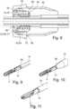
1 zeigt eine perspektivische Ansicht eines Instruments gemäß der vorliegenden Offenbarung,1 shows a perspective view of an instrument according to the present disclosure,2 zeigt eine perspektivische Ansicht eines distalen Teils des Instruments,2 shows a perspective view of a distal part of the instrument,3 zeigt eine vergrößerte perspektivische Ansicht eines proximalen Teils des Instruments,3 shows an enlarged perspective view of a proximal part of the instrument,4 bis 11 zeigen eine Ausbildung bzw. Aufnahme eines Isolationsmantels des Instruments;4 to 11 show a formation or inclusion of an insulating jacket of the instrument;12 zeigt eine Längsschnittdarstellung eines Handgriffs des Instruments;12 shows a longitudinal section of a handle of the instrument;13 und14 zeigen Längsschnittdarstellungen des Handgriffs in einer vollständig geöffneten bzw. geschlossenen Stellung (bzw. betätigten und unbetätigten Stellung) eines Werkzeugs des Instruments;13 and14 show longitudinal sectional views of the handle in a fully open or closed position (or actuated and unactuated position) of a tool of the instrument;15 und16 zeigen eine Überlastsicherungsfunktion des Instruments;15 and16 show an overload protection function of the instrument;17 zeigt eine Längsschnittdarstellung des Handgriffs des Instruments in einer Ladeposition;17 shows a longitudinal section of the handle of the instrument in a loading position;18 zeigt eine Längsschnittdarstellung eines distalen Endbereichs des Instruments; und18 shows a longitudinal section of a distal end portion of the instrument; and19 zeigt eine Querschnittsdarstellung im Bereich eines Demontageknopfs des Instruments.19 shows a cross-sectional view in the area of a disassembly button of the instrument.
Beschreibung von bevorzugten AusführungsformenDescription of preferred embodiments
Das Instrument 2 weist ein distal angeordnetes Werkzeug 4, eine proximal zu dem Werkzeug 4 angeordnete Schaftbaugruppe 6 und einen proximal (zu dem Werkzeug 4 und der Schaftbaugruppe 6) angeordneten Handgriff 8 auf. Das heißt, dass das Werkzeug 4 an einem distalen Ende (/Arbeitsende) der Schaftbaugruppe 6 ankoppelbar oder angekoppelt ist und ein proximales Ende (/Betätigungsende) der Schaftbaugruppe 6 an dem Handgriff 8 distal ankoppelbar/ankuppelbar oder angekoppelt/angekuppelt ist. Dabei sind proximal und distal auf einen Operateur (/Bediener/Betätiger/Benutzer) des Instruments 2 bezogen definiert.The
Das Instrument 2 weist das (distal angeordnete) Werkzeug 4 auf. Das Werkzeug 4 ist insbesondere mehrteilig aufgebaut und kann beispielsweise aus zwei schere-, klemmbacken-, zangen- oder pinzettenförmigen, gegeneinander/zueinander beweglichen, insbesondere zueinander verschwenkbaren Werkzeugbranchen (/elementen) 10 aufgebaut sein. Bei einem Betätigen des Werkzeugs 4 verschwenken die Werkzeugbranchen 10 relativ zueinander, wodurch sie sich öffnen bzw. schließen. Das Werkzeug 4 kann bzw. die Werkzeugbranchen 10 können zum Schneiden, Greifen, Halten und/oder Klemmen von Körpergewebe dienen. Die Werkzeugbranchen 10 sind insbesondere an der Schaftbaugruppe 6 um eine Werkzeugschwenkachse drehbar angelenkt, so dass zumindest eine der Werkzeugbranchen 10, vorzugsweise beide Werkzeugbranchen 10, relativ zu der Schaftbaugruppe 6 und damit auch relativ zu der jeweils anderen Werkzeugbranche 10 verschwenkt werden kann. Die Werkzeugschwenkachse ist insbesondere quer bzw. senkrecht zu einer distal-proximal-Richtung ausgerichtet. Die distal-proximal-Richtung entspricht insbesondere einer Längsachse der Schaftbaugruppe 6 (im Folgenden lediglich als eine Schaftachse bezeichnet). Das Werkzeug 4 ist insbesondere um seine Längsachse drehgekoppelt mit der Schaftbaugruppe 6 verbunden, so dass das Werkzeug 4 (als Ganzes) mit der Schaftbaugruppe 6 verdreht werden kann. Das Werkzeug 4 ist insbesondere aus einem Metall, vorzugsweise aus Stahl, ausgebildet.The
Das Instrument 2 bzw. die Schaftbaugruppe 6 weist einen Instrumentenschaft (/Rohrschaft) 12 auf, dessen Längsachse (/Rohrachse) insbesondere der Schaftachse entspricht. Der Instrumentenschaft 12 kann vorzugsweise translatorisch fest und vorzugsweise um die Schaftachse drehbar aufgenommen sein. Das Werkzeug 4 kann mit dem Instrumentenschaft 12 derart gekoppelt sein, dass eine Rotation des Instrumentenschafts 12 (um die Schaftachse) eine Rotation des Werkzeugs 4 (um die Schaftachse) hervorruft (/erzwingt/aktuiert). Insbesondere können das Werkzeug 4 und der Instrumentenschaft 12, vorzugsweise direkt, um die Schaftachse drehfest miteinander verbunden sein. Der Instrumentenschaft 12 ist insbesondere aus einem Metall, vorzugsweise aus Stahl, ausgebildet.The
Das Instrument 2 bzw. die Schaftbaugruppe 6 weist eine Transmission, vorzugsweise eine im Inneren/innerhalb des Instrumentenschafts 12 gelagerte (/aufgenommene/angeordnete) Zug-/Druckstange 14 auf, deren Längsachse (/Stangenachse) insbesondere der Schaftachse bzw. im Wesentlichen der distal-proximal-Richtung entspricht. Die Transmission (/die Zug-/Druckstange 14) kann translatorisch verschiebbar, vorzugsweise axial-/längsbeweglich/-verschieblich, d.h. translatorisch entlang der Schaftachse verschieblich, und vorzugsweise rotatorisch fest aufgenommen sein. Das Werkzeug 4 kann mit der Transmission (/Zug-/Druckstange 14) derart gekoppelt sein, dass eine Translationsbewegung, insbesondere Längsbewegung (entlang der Schaftachse) ein Betätigen des Werkzeugs 4, insbesondere eine Schwenkbewegung (bzw. Öffnen und Schließen) der Werkzeugbranchen 10 (um die Werkzeugschwenkachse), hervorruft (/erzwingt/aktuiert). Insbesondere können das Werkzeug 4 und die Zug-/Druckstange 14, vorzugsweise über einen Kopplungsmechanismus, miteinander verbunden sein. Das heißt, dass die Zug-/Druckstangen-Längsbewegung in eine distale Richtung/Schubrichtung das Öffnen (oder Schließen) des Werkzeugs 4 bzw. der Werkzeugbranchen 10 und in eine proximale Richtung/Zugrichtung das Schließen (oder Öffnen) des Werkzeugs 4 bzw. der Werkzeugbranchen 10 hervorruft (/erzwingt/aktuiert). Die Zug-/Druckstange 14 ist insbesondere aus einem Metall, vorzugsweise aus Stahl, ausgebildet.The
Das Instrument 2 bzw. die Schaftbaugruppe 6 weist einen insbesondere auf dem Instrumentenschaft 12 angeordneten Isolationsmantel 16 auf, dessen Längsachse (/Mantelachse) insbesondere der Schaftachse entspricht. Der Isolationsmantel 16 kann, insbesondere relativ zu dem Instrumentenschaft 12 und/oder der Zug-/Druckstange 14, axial-/längsbeweglich/-verschieblich, d.h. translatorisch entlang der Schaftachse verschieblich, und vorzugsweise (frei) drehbar aufgenommen sein. Der Isolationsmantel 16 ist hohl, vorzugsweise rohrförmig, ausgebildet und dient zur (radial) außenseitigen elektrischen Isolierung des Instrumentenschafts 12 und/oder der Zug-/Druckstange 14, insbesondere zwischen einem distalen Endbereich und einem proximalen Endbereich des Instrumentenschafts 12 und/oder der Zug-/Druckstange 14. Der Isolationsmantel 16 ist aus einem zum Instrumentenschaft 12 unterschiedliche Material, insbesondere aus einem Kunststoff, vorzugsweise aus PEEK, ausgebildet. Eine Ausbildung bzw. Aufnahme des Isolationsmantels 16 wird untenstehend näher beschrieben.The
Das Instrument 2 bzw. die Schaftbaugruppe 6 weist eine insbesondere auf dem Instrumentenschaft 12 angeordnete, vorzugsweise im Querschnitt ringförmige Kappe 18 auf. Durch eine (zentrale) Öffnung der Kappe 18 können der Instrumentenschaft 12, die Zug-/Druckstange 14 und/oder der Isolationsmantel 16 axial hindurchgeführt sein. Die Kappe 18 kann, insbesondere relativ zu dem Instrumentenschaft 12, translatorisch fest und vorzugsweise rotatorisch fest aufgenommen sein. Die Kappe 18 dient als Axialanschlag der Schaftbaugruppe 6 an dem Handgriff 8.The
Das Instrument 2 weist den (proximal angeordneten) Handgriff 8 auf. Der Handgriff 8 ist insbesondere nach Art eines Pistolengriffs bzw. als ein Pistolen-Handgriff ausgebildet. Der Handgriff 8 weist ein Getriebegehäuse 20 auf, das sich insbesondere von distal in Richtung proximal, d.h. in der distal-proximal-Richtung bzw. im Wesentlichen parallel zur/entlang der Schaftachse, erstreckt.The
Zudem weist der Handgriff 8 ein feststehendes Griffelement (/Griffteil) 21 auf. Das Griffelement 21 erstreckt sich insbesondere in einem Winkel, d.h. quer, zur distal-proximal-Richtung. Das Griffelement 21 kann an einem proximalen Endabschnitt des Getriebegehäuses 20 fixiert sein oder insbesondere an dem Getriebegehäuse 20 ausgebildet sein, d.h. integral mit dem Getriebegehäuse 20 verbunden sein. Insbesondere sind das Getriebegehäuse 20 und das Griffelement 21 fest miteinander verbunden.In addition, the
Weiter weist der Handgriff 8 einen an dem Getriebegehäuse 20 angelenkten, insbesondere fingergeführten bzw. fingerführbaren Betätigungshebel 22 auf. Der Betätigungshebel 22 ist insbesondere manuell betätigbar und weist eine Angriffsstelle zum Aufbringen einer Betätigungskraft (durch den Operateur) aus. Der Betätigungshebel 22 kann eine, vorzugsweise geschlossene bzw. im Wesentlichen ringförmige, Schlaufe zur Aufnahme von Fingern (vorzugsweise nicht eines Daumens) des Operateurs aufweisen, welche die Betätigungskraft-Angriffsstelle bildet. Der Betätigungshebel 22 kann schwenkbar aufgenommen sein. Der Betätigungshebel 22 ist insbesondere an dem Getriebegehäuse 20 um eine Betätigungshebelschwenkachse drehbar angelenkt, so dass der Betätigungshebel 22 relativ zu dem Getriebegehäuse 20, d.h. zu dem Griffelement 21 hin oder von dem Griffelement 21 weg, verschwenkt werden kann. Die Betätigungshebelschwenkachse ist insbesondere quer bzw. senkrecht zu der Schaftachse, d.h. der distal-proximal-Richtung. Durch eine manuelle Betätigung des Betätigungshebels 22, d.h. durch ein Aufbringen der Betätigungskraft an der Betätigungskraft-Angriffsstelle, insbesondere der Schlaufe, wird eine Schwenkbewegung des Betätigungshebels 22 (relativ zu dem Getriebegehäuse 20) hervorgerufen (/erzwungen/aktuiert). Die Schwenkbewegung des Betätigungshebels 22 zu dem Griffelement 21 hin, aktuiert etwa durch Schließen einer Hand des Operateurs/Zusammendrücken von Betätigungshebel 22 und Griffelement 21, wird im Folgenden lediglich als Verschwenken/Schwenkbewegung in eine Betätigungsrichtung bzw. Betätigen des Betätigungshebels 22 bezeichnet. Die Schwenkbewegung des Betätigungshebels 22 von dem Griffelement 21 weg, aktuiert etwa durch Öffnen einer Hand des Operateurs/Auseinanderdrücken von Betätigungshebel 22 und Griffelement 21, wird im Folgenden lediglich als Verschwenken/Schwenkbewegung in eine Rückstellrichtung bzw. Rückstellen des Betätigungshebels 22 bezeichnet.Furthermore, the
Das Instrument 2 bzw. der Handgriff 8 weist ein Getriebe 24 auf, das die (durch die manuelle Betätigung aktuierte) Schwenkbewegung des Betätigungshebels 22 in eine Translationsbewegung der Transmission, insbesondere in eine Längsbewegung der Zug-/Druckstange 14 überträgt. Das heißt, dass das Getriebe 24 die Schwenkbewegung des Betätigungshebels 22 mit der Längsbewegung der Zug-/Druckstange 14 (und damit (indirekt) mit dem Betätigen des Werkzeugs 4 bzw. dem Öffnen und dem Schließen der Werkzeugbranchen 10) koppelt. Mit anderen Worten aktuiert das Betätigen des Betätigungshebels 22 die Längsbewegung der Zug-/Druckstange 14 in die Schubrichtung (oder in die Zugrichtung) und das Rückstellen des Betätigungshebels 22 die Längsbewegung der Zug-/Druckstange 14 in die Zugrichtung (oder in die Schubrichtung) (welche wiederum das Betätigen (bzw. Öffnen oder Schließen) des Werkzeugs 4 hervorruft). Das Getriebe 24 kann vorzugsweise größtenteils oder vollständig innerhalb des Getriebegehäuses 20 angeordnet sein bzw. von dem Getriebegehäuse 20 nach außen hin abgedeckt sein. Eine Ausbildung des Getriebes 24 wird untenstehend näher beschrieben.The
Das Instrument 2 bzw. der Handgriff 8 weist einen, insbesondere an einem distalen Ende des Handgriffs 8 angeordneten Drehstern 26 auf, dessen Längsachse (/Sternachse) insbesondere der Schaftachse entspricht. Der Drehstern 26 kann, insbesondere relativ zu dem Getriebegehäuse 20, vorzugsweise translatorisch fest und vorzugsweise um die Schaftachse drehbar aufgenommen sein. Durch eine (zentrale) Öffnung des Drehsterns 26 können der Instrumentenschaft 12, die Zug-/Druckstange 14 und/oder der Isolationsmantel 16 axial hindurchgeführt oder hindurchführbar sein. Der Drehstern 26 kann mit dem Instrumentenschaft 12 derart koppelbar oder gekoppelt sein, dass eine Rotation des Drehsterns 26 (um die Schaftachse) die Rotation des Instrumentenschafts 12 (um die Schaftachse) hervorruft (/erzwingt/aktuiert) (welche wiederum die Rotation des Werkzeugs 4 hervorruft). Insbesondere können der Drehstern 26 und der Instrumentenschaft 12, vorzugsweise direkt oder über ein mit dem Instrumentenschaft 12 (fest) verbundenes Bauteil, um die Schaftachse drehfest miteinander verbunden sein.The
Das Instrument 2 bzw. der Handgriff 8 weist einen Demontageknopf 28 auf, bei dessen Betätigung (/Drücken) die Schaftbaugruppe 6 und der Handgriff 8 demontierbar sind, d.h. die Schaftbaugruppe 6 aus dem Handgriff 8 auskoppelbar ist. Eine Ausbildung des Demontageknopfs 28 wird untenstehend näher beschrieben.The
Das Instrument 2 bzw. der Handgriff 8 weist einen Hochfrequenzanschluss, insbesondere einen HF-Pin 30 auf, durch den das Werkzeug 4, insbesondere die Werkzeugbranchen 10, mit einer Hochfrequenzspannung beaufschlagbar ist. Der HF-Pin 30 kann, insbesondere relativ zu dem Getriebegehäuse 20, vorzugsweise translatorisch fest und vorzugsweise rotatorisch fest aufgenommen sein. Der HF-Pin 30 kann in Kontakt mit dem Instrumentenschaft 12 und/oder der Zug-/Druckstange 14 sein oder bringbar sein, um die Hochfrequenzspannung durch das Material des Instrumentenschafts 12 und/oder der Zug-/Druckstange 14 an das Werkzeug 4 zu übertragen. Der HF-Pin 30 kann als ein bipolarer oder als ein monopolarer HF-Pin ausgebildet sein.The
Der Handgriff 8 weist einen Rastmechanismus 32 auf, durch den eine Schwenkposition des Betätigungshebels 22 in vorbestimmten Rastpositionen feststellbar ist. Der Rastmechanismus 32 kann aus einem am Griffelement 21 (fest) angebrachten Rastbügel und einer am Betätigungshebel 22 (fest) angebrachten Raste aufgebaut sein.The
Der Handgriff 8 weist einen Taster 34 auf, mit dem eine Beaufschlagung des Werkzeugs 4 mit der Hochfrequenzspannung ausgelöst werden kann. Alternativ kann der Taster 34 zur Entriegelung des Rastmechanismus 32 dienen.The
Die Ausbildung bzw. Aufnahme des Isolationsmantels 16 wird mit Bezugnahme auf
Der Isolationsmantel 16 ist, wie oben beschrieben, axial verschieblich (/frei schwimmend) auf dem Instrumentenschaft 12 aufgenommen. An dem Instrument 2 ist ein proximaler Axialanschlag 36 zur Begrenzung einer proximal gerichteten Axialbewegung (in Richtung zum Handgriff 8 hin) des Isolationsmantels 16 ausgebildet.As described above, the
Gemäß einem Aspekt der Offenbarung ist der proximale Axialanschlag 36 axial verschieblich auf dem Instrumentenschaft 12 aufgenommen/angeordnet. Dabei ist der proximale Axialanschlag 36 distal/in eine distale Richtung axialvorgespannt. Das heißt, dass der proximale Axialanschlag 36 eine distal gerichtete Axialkraft auf den Isolationsmantel 16 aufbringt bzw. der proximale Axialanschlag 36 durch eine axiale Vorspannung distal/in die distale Richtung gedrückt wird.According to one aspect of the disclosure, the proximal axial stop 36 is accommodated/arranged on the
In einem abgekühlten Zustand befindet sich der Isolationsmantel 16 in seiner Montageposition und liegt axial an dem proximalen Axialanschlag 36 an. Durch eine Erwärmung, etwa bei einer Sterilisation des Instruments 2 und/oder der Schaftbaugruppe 6, dehnen sich der Isolationsmantel 16 und der Instrumentenschaft 12, aufgrund ihrer unterschiedlichen Wärmeausdehnungskoeffizienten, unterschiedlich weit aus, so dass es zu einem axialen Verrutschen des Isolationsmantels 16 auf dem Instrumentenschaft 12 kommt. Der proximale Axialanschlag 36 verschiebt sich durch eine Ausdehnung des Isolationsmantels 16 in eine proximale Richtung, wodurch die axiale Vorspannung auf den proximalen Axialanschlag 36 zunimmt. Wenn der Isolationsmantel 16 wieder abkühlt und sich zusammenzieht, wird der Isolationsmantel 16 durch die axiale Vorspannung des proximalen Axialanschlag 36 in seine Montageposition zurückgeschoben.When cooled, the
Der Adapter 42 kann vorzugsweise einen distalen Anschlag 44 zur Begrenzung einer distal gerichteten Axialbewegung (in Richtung zum Werkzeug 4 hin) des axialverschieblichen proximalen Axialanschlags 36 (d.h. der Scheibe 38 und/oder der Feder 40) aufweisen. Dabei kann eine Axialposition des distalen Anschlags 44 vorzugsweise in Abhängigkeit eines Wärmeausdehungsverhaltens des Isolationsmantels 16 und/oder des Instrumentenschafts 12 festgelegt sein. Insbesondere kann die Axialposition so festgelegt sein, dass der Isolationsmantel 16 in dem abgekühlten Zustand an dem proximalen Axialanschlag 36 (sowie einem später beschriebenen distalen Axialanschlag 80) axial anliegt (d.h., dass sich der Isolationsmantel 16 nicht aufgrund seines Wärmeausdehungsverhaltens weiter in die distale Richtung zurückziehen soll als der proximale Axialanschlag 36 aufgrund des distalen Anschlags 44 in die distale Richtung gedrückt werden kann). Der distale Anschlag 44 kann insbesondere an einem sich radial nach innen (insbesondere weiter über einen Außenumfang des proximalen Axialanschlags 36/der Scheibe 38 hinaus nach innen) erstreckenden Abschnitt des Adapters 42 ausgebildet sein.The
Der Adapter 42 kann vorzugsweise eine Aufnahmeschale 46 mit einer Einlegeöffnung zum (axialen) Einlegen (/Einschieben/Einsetzen) des proximalen Axialanschlags 36, insbesondere der Scheibe 38 und/oder der Feder 40, aufweisen. Die Einlegeöffnung kann insbesondere einen größeren Außendurchmesser als der proximale Axialanschlag 36, insbesondere als die Scheibe 38 und/oder die Feder 40, aufweisen. Die Einlegeöffnung kann vorzugsweise auf einer proximalen Seite des Adapters 42 ausgebildet sein. Die Aufnahmeschale 46 kann den distalen Anschlag 44 vorzugsweise direkt/integral ausbilden.The
Der Adapter 42 kann vorzugsweise eine distale Öffnung 48 aufweisen, die insbesondere im Wesentlichen so groß ist wie ein Außendurchmesser des Isolationsmantels 16 (bzw. geringfügig größer um die Axialverschiebbarkeit des Isolationsmantels 16 zu gewährleisten), durch die der Isolationsmantel 16 (sowie der Instrumentenschaft 12 und/oder die Zug-/Druckstange 14) axial hindurchgeführt oder hindurchführbar ist. Die distale Öffnung 48 kann (direkt/integral) an einem Innenumfang (/-durchmesser) der Aufnahmeschale 46 ausgebildet sein.The
Der erste bzw. zweite proximale Axialanschlag 50, 52 ist vorzugsweise an einer insbesondere auf dem Instrumentenschaft 12 aufgenommenen (etwa auf einen Außenumfang des Instrumentenschafts 12 aufgesteckte/aufgesetzte) ringförmigen ersten Scheibe 54 bzw. zweiten Scheibe 56 ausgebildet. Die axiale Vorspannung des ersten bzw. zweiten proximalen Axialanschlags 50, 52 ist vorzugsweise durch ein insbesondere auf dem Instrumentenschaft 12 angeordnetes, axial vorspannendes Druckelement, insbesondere eine erste Feder 58 bzw. zweite Feder 60, vorzugsweise in Form einer Schraubenfeder, realisiert. Die erste bzw. zweite Feder 58, 60 kann vorzugsweise direkt an der ersten bzw. zweiten Scheibe 54, 56 anliegen. Alternativ kann die erste bzw. zweite Feder 58, 60 vorzugsweise direkt an dem ersten bzw. zweiten Isolationsmantel 16 anliegen, so dass eine axiale Stirnfläche der ersten bzw. zweiten Feder 58, 60 den ersten bzw. zweiten proximalen Axialanschlag 50, 52 ausbildet.The first or second proximal axial stop 50, 52 is preferably formed on an annular first disk 54 or second disk 56, which is received in particular on the instrument shaft 12 (e.g., placed/fitted onto an outer circumference of the instrument shaft 12). The axial preload of the first or second proximal axial stop 50, 52 is preferably realized by an axially preloading pressure element, in particular a
In der proximalen Aufnahme ist insbesondere immer nur ein erster oder zweiter Isolationsmantel 16 eingesetzt.
Vorzugsweise können die erste Feder 58 und die zweite Feder 60 unterschiedliche Federhärten aufweisen. Insbesondere kann die zweite Feder 60 eine größere Federhärte als die erste Feder aufweisen.Preferably, the
Vorzugsweise können die erste Feder 58 und die zweite Feder 60 radial geschachtelt/ineinander angeordnet sein. Insbesondere kann die erste Feder 58 radial innerhalb der zweiten Feder 60 angeordnet sein.Preferably, the
Vorzugsweise können die erste Scheibe 54 und die zweite Scheibe 56 axial aneinander anliegen. Insbesondere kann die erste Scheibe 54 proximal der zweiten Scheibe 56 angeordnet sein.Preferably, the first disk 54 and the second disk 56 can abut one another axially. In particular, the first disk 54 can be arranged proximal to the second disk 56.
Vorzugsweise können die erste Scheibe 54 und die zweite Scheibe 56 unterschiedliche Innendurchmesser aufweisen. Insbesondere kann die distal angeordnete Scheibe 54, 56, hier die zweite Scheibe 56, einen größeren Innendurchmesser als die proximal angeordnete Scheibe 54, 56, hier die erste Scheibe 54, aufweisen, so dass der jeweilige Isolationsmantel 16 zum axialen Anliegen an der proximal angeordneten Scheibe 54, 56, hier der ersten Scheibe 54, durch die distal angeordnete Scheibe 54, 56, hier durch die zweite Scheibe 56, axial hindurchführbar ist. Alternativ kann die distal angeordnete Scheibe 54, 56 ein Durchgangsloch aufweisen, durch das der jeweilige Isolationsmantel 16 zum axialen Anliegen an der proximal angeordneten Scheibe 54, 56 hindurchführbar ist.Preferably, the first disk 54 and the second disk 56 can have different inner diameters. In particular, the distally arranged disk 54, 56, here the second disk 56, can have a larger inner diameter than the proximally arranged disk 54, 56, here the first disk 54, so that the respective insulating
Der erste bzw. zweite proximale Axialanschlag 50, 52 (d.h. die erste bzw. zweite Scheibe 54, 56 und/oder die erste bzw. zweite Feder 58, 60) kann vorzugsweise innerhalb eines insbesondere auf dem Instrumentenschaft 12 aufgenommenen, kapselartigen Adapters 62 angeordnet sein. Der Adapter 62 kann zur (radial) außenseitigen elektrischen Isolierung des Instrumentenschafts 12 und/oder der Zug-/Druckstange 14 dienen. Der Adapter 62 kann vorzugsweise axialfest mit dem Instrumentenschaft 12 verbunden sein.The first or second proximal axial stop 50, 52 (i.e. the first or second disk 54, 56 and/or the first or
Der Adapter 62 kann vorzugsweise einen distalen Anschlag 64 zur Begrenzung einer distal gerichteten Axialbewegung (in Richtung zum Werkzeug 4 hin) des axialverschieblichen ersten bzw. zweiten proximalen Axialanschlags 50, 52 aufweisen. Dabei kann eine Axialposition des distalen Anschlags 64 vorzugsweise in Abhängigkeit eines Wärmeausdehungsverhaltens des Isolationsmantels 16 und/oder des Instrumentenschafts 12 festgelegt sein. Insbesondere kann die Axialposition so festgelegt sein, dass der Isolationsmantel 16 in dem abgekühlten Zustand an dem ersten bzw. zweiten proximalen Axialanschlag 50, 52 (sowie einem später beschriebenen distalen Axialanschlag 80) axial anliegt (d.h., dass sich der Isolationsmantel 16 nicht aufgrund seines Wärmeausdehungsverhaltens weiter in die distale Richtung zurückziehen soll als der erste bzw. zweite proximale Axialanschlag 50, 52 aufgrund des distalen Anschlags 64 in die distale Richtung gedrückt werden kann). Der distale Anschlag 64 kann insbesondere an einem sich radial nach innen (insbesondere weiter über einen Außenumfang des ersten bzw. zweiten proximalen Axialanschlags 50, 52 hinaus nach innen) erstreckenden Abschnitt des Adapters 62 ausgebildet sein.The
Der Adapter 62 kann vorzugsweise eine Aufnahmeschale 66 mit einer Einlegeöffnung zum (axialen) Einlegen (/Einschieben/Einsetzen) des ersten bzw. zweiten proximalen Axialanschlags 50, 52, insbesondere der ersten bzw. zweiten Scheibe 54, 56 und/oder der ersten bzw. zweiten Feder 58, 60, aufweisen. Die Einlegeöffnung kann insbesondere einen größeren Außendurchmesser als der erste bzw. zweite proximale Axialanschlag 50, 52, insbesondere als die erste bzw. zweite Scheibe 54, 56 und/oder die erste bzw. zweite Feder 58, 60, aufweisen. Die Einlegeöffnung kann vorzugsweise auf einer distalen Seite des Adapters 62 ausgebildet sein.The
Der Adapter 62 kann vorzugsweise eine distale Öffnung 68 aufweisen, deren Außendurchmesser insbesondere im Wesentlichen dem des Isolationsmantels 16 (bzw. geringfügig größer ist um die Axialverschiebbarkeit des Isolationsmantels 16 zu gewährleisten), durch die der Isolationsmantel 16 (sowie der Instrumentenschaft 12 und/oder die Zug-/Druckstange 14) axial hindurchgeführt oder hindurchführbar ist. Alternativ kann die distale Öffnung 68 im Wesentlichen so groß wie ein Außendurchmesser des Instrumentenschafts 12 sein, wenn der Isolationsmantel 16 zur Kontaktierung der distal angeordneten Scheibe 54, 56, hier der ersten Scheibe 54, durch das Durchgangsloch hindurchgreift.The
Der Adapter 62 eine vorzugsweise separat von der Aufnahmeschale 66 ausgebildete Kappe 70 aufweisen, die von distaler Seite auf die Aufnahmeschale 66 aufsteckbar, insbesondere aufschraubbar ist. Die Kappe 70 kann den distalen Anschlag 64 vorzugsweise direkt/integral ausbilden. Der Adapter 62 kann vorzugsweise einen Axialdeckel 72 aufweisen, der die Einlegeöffnung an der Aufnahmeschale 66 verschließt und die distale Öffnung 68 an seinem Innenumfang (/-durchmesser) (direkt/integral) ausbildet. Der Axialdeckel 72 kann vorzugsweise durch die erste Scheibe 54 oder die zweite Scheibe 56 gebildet sein, insbesondere durch die proximal angeordnete Scheibe 54, 56, hier die zweite Scheibe 56. Alternativ kann die distale Öffnung 68 (direkt/integral) an einem Innenumfang (/-durchmesser) der Kappe 70 ausgebildet sein, wenn der Isolationsmantel 16 zur Kontaktierung der distal angeordneten Scheibe 54, 56, hier der ersten Scheibe 54, durch ein Durchgangsloch in der Kappe 70 hindurchgreift.The
An dem Instrument 2, insbesondere an dem Instrumentenschaft 12 (oder einem damit (translationsfest) verbundenen Bauteil), ist insbesondere ein distaler Axialanschlag 80 zur Begrenzung einer distal gerichteten Axialbewegung (in Richtung zum Werkzeug 4 hin) des Isolationsmantels 16 ausgebildet. Der distale Axialanschlag 80 kann axialfest zu dem Instrumentenschaft 12 aufgenommen sein, insbesondere axialfest mit dem Instrumentenschaft 12 verbunden bzw. an dem Instrumentenschaft 12 ausgebildet sein. In
Dabei ist die Betätigungshebelschwenkachse, um die der Betätigungshebel 22 an dem Getriebegehäuse 20 drehbar angelenkt ist, insbesondere zwischen der Translationsachse der Translationsbewegung der Transmission, insbesondere der Schaftachse (d.h. der Längsachse des Instrumentenschafts 12 bzw. der Zug-/Druckstange 14), und einem proximalen Endbereich des Betätigungshebels 22 (d.h. der Betätigungskraft-Angriffsstelle zum Aufbringen der Betätigungskraft) angeordnet. Mit anderen Worten befindet sich die Betätigungshebelschwenkachse (bei Benutzung des Instruments 2 in Vertikalrichtung) unterhalb der Schaftachse.The actuating lever pivot axis, about which the
Gemäß einem Aspekt der vorliegenden Offenbarung ist das Getriebe 24 so ausgebildet ist, dass eine Schwenkbewegung des Betätigungshebels 22 hin zum Griffelement 21 in eine Translationsbewegung der Transmission 14 in Richtung proximal transformiert wird. Das heißt, dass die Schwenkbewegung des Betätigungshebels 22 hin zum Griffelement 21 (das Betätigen des Betätigungshebels 22) in eine proximal gerichtete Längsbewegung der Zug-/Druckstange 14 (eine Zugbewegung der Zug-/Druckstange 14) gewandelt wird.According to one aspect of the present disclosure, the
Insbesondere ist das Getriebe 24 dazu zweiteilig oder mehrteilig ausgebildet. Vorzugsweise bildet das Getriebe 24 einen Kraftübertragungszug (vom Betätigungshebel 22 zur Transmission (Zug-/Druckstange 14)).In particular, the
Der Kraftübertragungszug weist ein erstes Drehteil (/Stellhebel) 82 auf. Das erste Drehteil 82 steht mit dem Betätigungshebel 22 in Wirkeingriff. Das heißt, dass die Schwenkbewegung des Betätigungshebels 22 mit einer Rotation des erstes Drehteils 82 gekoppelt ist. Das erste Drehteil 82 ist an dem Getriebegehäuse 20 um eine erste Drehachse drehbar angelenkt. Die erste Drehachse ist insbesondere quer bzw. senkrecht zu der Schaftachse. Das erste Drehteil 82 ist insbesondere separat zu dem Betätigungshebel 22 ausgebildet, kann aber alternativ auch an diesem (d.h. an einem Abschnitt des Betätigungshebels 22) ausgebildet sein, auch wenn dies nicht dargestellt ist.The power transmission cable has a first rotating part (/adjusting lever) 82. The first
Der Kraftübertragungszug weist ein zweites Drehteil (/Aufnahmeelement/Schließelement) 84 auf. Das zweite Drehteil 84 steht mit dem ersten Drehteil 82 unter Drehrichtungsumkehr in Wirkeingriff, vorzugsweise in Verzahnungseingriff. Das heißt, dass die Rotation des ersten Drehteils 82 mit einer Rotation des zweiten Drehteils 84 gekoppelt ist, und das erste Drehteil 82 und das zweite Drehteil 84 in unterschiedliche Drehrichtungen rotieren. Das zweite Drehteil 84 ist an dem Getriebegehäuse 20 um eine zweite Drehachse drehbar angelenkt. Die zweite Drehachse ist insbesondere quer bzw. senkrecht zu der Schaftachse. Die zweite Drehachse ist vorzugsweise parallel versetzt zu der ersten Drehachse. Das zweite Drehteil 84 hat vorzugsweise einen Kopplungsabschnitt 86 für die Transmission (/ Zug-/Druckstange 14). Der Kopplungsabschnitt 86 ist insbesondere mit der Transmission (/Zug-/Druckstange 14) in Wirkeingriff stehend oder bringbar. Das heißt, dass die Rotation des zweiten Drehteils 84 über den Kopplungsabschnitt 86 mit der Translationsbewegung der Transmission, insbesondere der Längsbewegung der Zug-/Druckstange 14, gekoppelt oder koppelbar ist.The power transmission cable has a second rotating part (/receiving element/closing element) 84. The second
Dazu können das erste Drehteil 82 und das zweite Drehteil 84 miteinander in Verzahnungseingriff stehende Zähne aufweisen. Die Verzahnung kann beispielsweise als eine Evolventenverzahnung ausgebildet sein. Durch den Verzahnungseingriff rotieren das erste Drehteil 82 und das zweite Drehteil 84 in unterschiedliche Drehrichtungen. Dies hat zur Folge, dass die Schwenkbewegung des Betätigungshebels 22 in der Betätigungsrichtung die Längsbewegung der Zug-/Druckstange 14 in die Zugrichtung und die Schwenkbewegung des Betätigungshebels 22 in der Rückstellrichtung die Längsbewegung der Zug-/Druckstange 14 in die Schubrichtung hervorruft (/erzwingt/aktuiert).For this purpose, the first
Vorzugsweise kann der Instrumentenschaft 12 in gekoppeltem Zustand als Anschlag für die Schwenkbewegung des Betätigungshebels 22, d.h. als Aufschwenkbegrenzung für den Betätigungshebel 22, bzw. als Rotationsbegrenzung für das erste Drehteil 82 und das zweite Drehteil 84 bzw. als Translationsbegrenzung für die Transmission, insbesondere als Längsbegrenzung für die Zug-/Druckstange 14 dienen. Das heißt, dass der Betätigungshebel 22 (nur) innerhalb eines, vorzugsweise beidseitig begrenzten Schwenkbereichs verschwenkbar ist bzw. das erste Drehteil 82 und das zweite Drehteil 84 (nur) innerhalb eines, vorzugsweise beidseitig begrenzten Rotationsbereichs bzw. die Transmission (/Zug-/Druckstange 14) (nur) innerhalb eines, vorzugsweise beidseitig begrenzten Translationsbereichs (/Längsbereich/Arbeitsbereich) längsbeweglich ist, d.h. einen maximalen Hub der Längsbewegung hat. Durch die Kopplung zwischen der Transmission (/Zug-/Druckstange 14) und dem Getriebe 24 (insbesondere dem zweiten Drehteil 82), der Kraftübertragung innerhalb des Getriebes 24 (insbesondere dem zweiten Drehteil 82 und dem ersten Drehteil 82) sowie der Kopplung zwischen dem Getriebe 24 (insbesondere dem ersten Drehteil 82) und dem Betätigungshebel 22 kann der Anschlag am Instrumentenschaft 12 für alle miteinander gekoppelten (oder koppelbaren) Bewegungen dienen.Preferably, the
Vorzugsweise kann das Getriebe 24 ein Übersetzungsverhältnis von 1:1 aufweisen. Insbesondere können die Zähne des ersten Drehteils 82 und des zweiten Drehteils 84 auf demselben Durchmesser angeordnet sein. Alternativ könnten die Zähne des ersten Drehteils 82 und des zweiten Drehteils 84 auf unterschiedlichen Durchmessern angeordnet sein, um eine Untersetzung oder eine Übersetzung zu realisieren, auch wenn es nicht dargestellt ist.Preferably, the
Vorzugsweise können die Zähne des ersten Drehteils 82 und/oder die Zähne des zweiten Drehteils 84 (nur) umfangsseitig abschnittsweise, d.h. nicht über einen gesamten Umfang, ausgebildet sein. Dabei kann eine Anzahl der Zähne des ersten Drehteils 82 und/oder des zweiten Drehteils 84, d.h. eine Dimensionierung der umfangsseitig abschnittsweisen Ausbildung, vorzugsweise in Abhängigkeit des maximalen Hubs der Längsbewegung/des begrenzten Längsbereichs der Zug-/Druckstange 14 festgelegt sein. Insbesondere können das erste Drehteil 82 und/oder das zweite Drehteil 84 zwei bis fünf Zähne, vorzugsweise zwei, drei oder vier Zähne, aufweisen. Alternativ könnten die Zähne des ersten Drehteils 82 und/oder des zweiten Drehteils 84 über den gesamten Umfang ausgebildet sein, auch wenn dies nicht dargestellt ist.Preferably, the teeth of the first
Vorzugsweise kann der Kopplungsabschnitt 86 des zweiten Drehteils 84 als eine axial hinterschnittene Ausnehmung 88 ausgebildet sein, in welche die Transmission (Zug-/Druckstange 14) axial hinterschneidend eingreifen kann oder eingreift, um die Drehung des zweiten Drehteils 84 mit der Translationsbewegung (/Längsbewegung der Zug-/Druckstange 14) zu koppeln. Dazu kann die Zug-/Druckstange 14 an ihrem proximalen Ende (Endbereich) eine, insbesondere in Form eines Kugeldruckstücks 90 ausgebildete, radiale (gegenüber einem axial angrenzenden Bereich vergrößerte) Verdickung aufweisen, die in die Ausnehmung 88 des zweiten Drehteils 84 axial hinterschneidend eingreift.Preferably, the coupling section 86 of the second
Vorzugsweise kann das Getriebe 24 einen an dem zweite Drehteil 84 (drehbar) angelenkten Führungsdorn 92 aufweisen. Der Führungsdorn 92 ist insbesondere an dem zweiten Drehteil 84 um eine Dorndrehachse drehbar angelenkt, so dass das zweite Drehteil 84 und der Führungsdorn 92 relativ zueinander verdreht werden können. Die Dorndrehachse ist insbesondere quer bzw. senkrecht zu der Schaftachse. Vorzugsweise kann die Dorndrehachse parallelversetzt zu der zweiten Drehachse (und/oder der ersten Drehachse) sein. Der Führungsdorn 92 ist längsgeführt, d.h. (nur) entlang seiner Längsachse verschieblich, in dem Getriebegehäuse 20 aufgenommen. Dabei kann die Längsachse des Führungsdorns 92 insbesondere parallelversetzt zu der Schaftachse sein. Vorzugsweise ist der Führungsdorn 92, über eine Feder 94, federvorgespannt in dem Getriebegehäuse 20 aufgenommen. Vorzugsweise kann die Federvorspannung des Führungsdorns 92 der Schwenkbewegung des Betätigungshebels 22 hin zum Griffelement 21 (d.h. der Betätigung) entgegenwirken.Preferably, the
Vorzugsweise kann der Handgriff 8 einen Außengriff 96 und einen fest mit dem Außengriff 96 verbundenen, beispielsweise angeschraubten Innengriff 98 aufweisen. Vorzugsweise kann der Innengriff 98 von dem Außengriff 96 außenseitig abgedeckt sein. Insbesondere kann das zweite Drehteil 84 drehbar an dem Innengriff 98 angelenkt sein. Insbesondere kann der Führungsdorn 92 drehbar an dem Innengriff 98 angelenkt sein. Zudem kann der Führungsdorn 92 in einer Aussparung 100 in dem Innengriff 98 längsgeführt aufgenommen sein.Preferably, the
Gemäß einem Aspekt der vorliegenden Offenbarung weist das Getriebe 24 das insbesondere an dem Getriebegehäuse 20 (drehbar) angelenkte erste Drehteil 82 sowie ein die Schwenkbewegung des Betätigungshebels 22 mit einer Rotation des ersten Drehteils 82 koppelndes, elastisches Überlastsicherungselement 102 auf (vgl. insbesondere auch
Vorzugsweise können der Betätigungshebel 22 und das erste Drehteil 82 um dieselbe Achse schwenkbar bzw. drehbar an dem Getriebegehäuse 20 angelenkt sein. Das heißt, dass die Betätigungshebelschwenkachse vorzugsweise der ersten Drehachse entspricht.Preferably, the actuating
Vorzugsweise kann der Betätigungshebel 22 eine Ausnehmung 104 aufweisen, in der das Überlastsicherungselement 102 aufgenommen ist. Insbesondere kann das Überlastsicherungselement 102 vollständig innerhalb der Ausnehmung 104 angeordnet sein. Das heißt, dass das Überlastsicherungselement 102 vorzugsweise nach außen hin durch den Betätigungshebel 22 abgedeckt ist.Preferably, the actuating
Vorzugsweise kann das Überlastsicherungselement 102 lose in der Ausnehmung 104 aufgenommen sein, d.h. nicht fest mit dem Betätigungshebel 22 und/oder dem ersten Drehteil 82 verbunden sein. Insbesondere kann das Überlastsicherungselement 102 längsgeführt, d.h. d.h. (nur) entlang seiner Längsachse verschieblich bzw. elastisch komprimierbar bzw. verbiegbar in der Ausnehmung 104 aufgenommen sein.Preferably, the
Wie oben beschrieben, kann der Betätigungshebel 22 in die Betätigungsrichtung, d.h. in die Richtung von dem Betätigungshebel 22 aus zu dem Griffelement 21 hin, aktuiert etwa durch Schließen einer Hand des Operateurs/Zusammendrücken von Betätigungshebel 22 und Griffelement 21, und in die Rückstellrichtung, d.h. in die Richtung von dem Betätigungshebel 22 aus von dem Griffelement 21 weg, aktuiert etwa durch Öffnen einer Hand des Operateurs/Auseinanderdrücken von Betätigungshebel 22 und Griffelement 21, verschwenkt werden, d.h. betätigt und rückgestellt werden.As described above, the actuating
Dabei kann das Überlastsicherungselement 102 vorzugsweise so angeordnet sein, dass es (nur/ausschließlich) in der Betätigungsrichtung (und nicht in der Rückstellrichtung) wirkt. Das heißt, dass das Überlastsicherungselement 102 nur die Schwenkbewegung des Betätigungshebels 22 zum Griffelement 21 hin begrenzt/dämpft/vor Überlast sichert/schützt. Insbesondere können eine Betätigungsübertragungsfläche 106 des Betätigungshebels 22 und eine Rückstellübertragungsfläche 108 des Betätigungshebels 22 voneinander getrennt, d.h. an unterschiedlichen Flächen, ausgebildet sein. Das heißt, dass der Betätigungshebel 22 und das erste Drehteil 82 nicht fest miteinander verbunden sind, und eine Kraftübertragung bei dem Betätigen des Betätigungshebels 22 über die über das Überlastsicherungselement 102 mit dem ersten Drehteil 82 gekoppelte Betätigungsübertragungsfläche 106 und eine Kraftübertragung bei dem Rückstellen des Betätigungshebels 22 (direkt) über die an dem ersten Drehteil 82 anliegende gekoppelte Rückstellübertragungsfläche 108 erfolgt.The
Zudem kann das Überlastsicherungselement 102 vorzugsweise so angeordnet und dimensioniert sein, dass eine anfängliche (anfänglich im Sinne der Betätigung, d.h. ausgehend von der Schwenkbewegung aus einer unbetätigten Stellung des Betätigungshebels 22) Kraftübertragung über das Überlastsicherungselement 102 zwischen dem Betätigungshebel 22 und dem ersten Drehteil 82 ein im Wesentlichen lineares Übertragungsverhalten aufweist. Das heißt, dass die Kopplung über das Überlastsicherungselement 102 bei der anfänglichen Kraftübertragung, insbesondere bei Kraftübertragung innerhalb des „normalen“ Arbeitsbereichs (und ohne Widerstand am Werkzeug 4), quasi starr/unelastisch ist.In addition, the
Insbesondere kann das Überlastsicherungselement 102 vorzugsweise so angeordnet und dimensioniert sein, dass das Überlastsicherungselement erst ab einer über den Betätigungshebel 22 aufgebrachten Betätigungskraft größer 200 N, vorzugsweise größer 300 N, (aber maximal erst ab einer über den Betätigungshebel 22 aufgebrachten Betätigungskraft von 1000 N) komprimiert wird.In particular, the
Gemäß einem Aspekt der vorliegenden Offenbarung kann der Instrumentenschaft 12 an den Handgriff 8 gekoppelt oder koppelbar sein und in gekoppeltem Zustand als Anschlag für die Schwenkbewegung des Betätigungshebels 22 (und der im Kraftübertragungszug damit gekoppelten Bauteile) dienen. Das heißt, dass der Instrumentenschaft 12 im gekoppelten Zustand als Aufschwenkbegrenzung für den Betätigungshebel 22, sowie als Translationsbegrenzung für die Transmission bzw. Längsbegrenzung für die Zug-/Druckstange 14, und damit als Wegbegrenzung für das Werkzeug 4 dient. Das heißt auch, dass in einem entkoppelten Zustand des Instrumentenschafts 12 die Anschlagsfunktion für die Schwenkbewegung des Betätigungshebels 22 sowie die Translationsbegrenzung für die Transmission bzw. die Längsbegrenzung für die Zug-/Druckstange 14, und damit die Wegbegrenzung für das Werkzeug 4 entfällt, so dass die beweglich geführten oder angelenkten Bestandteile des Kraftübertragungszugs des Getriebes 24 bzw. des Instruments 2 sich frei (bezüglich ihres Freiheitsgrads/ihrer aufgrund einer entsprechenden Lagerung/Aufnahme bzw. Anbringung möglichen Bewegung) bewegen können.According to one aspect of the present disclosure, the
Dabei kann der Instrumentenschaft 12 derart als Anschlag dienen, dass eine Entkopplung der Transmission (/Zug-/Druckstange 14) von dem Getriebe 24 nur im entkoppelten Zustand des Instrumentenschafts 12 vom Handgriff 8 infolge des Wegfalls seiner Anschlagfunktion möglich ist. Das heißt, dass eine Entkopplung der Transmission (/Zug-/Druckstange 14) von dem Getriebe 24 im am Handgriff 8 gekoppelten Zustand des Instrumentenschafts 12 infolge dessen Anschlagsfunktion gesperrt ist.The
Wie oben beschrieben, kann der durch den Instrumentenschaft 12 gebildete Anschlag vorzugsweise als ein die Translationsbewegung der Transmission (/die Längsbewegung der Zug-/Druckstange 14) insbesondere beidseitig begrenzender Axialanschlag ausgebildet sein.As described above, the stop formed by the
Beispielsweise kann der Anschlag dadurch gebildet sein, dass die Transmission (/Zug-/Druckstange 14) einen Zapfen 110 hat, der in einer Kulisse 112 an dem Instrumentenschaft 12 aufgenommen ist, so dass bei am Kulissenrand anliegendem Zapfen 110 eine weitere Translationsbewegung (in Richtung des Kulissenrands) unterbunden ist (vgl.
Vorzugsweise kann das Getriebe 24 das mit dem Betätigungshebel 22 in Wirkverbindung stehende zweite Drehteil 84 aufweisen, dessen Rotation über eine (erste) axiale Formschlussverbindung mit der Translationsbewegung der Transmission (/der Längsbewegung der Zug-/Druckstange 14) koppelbar oder gekoppelt ist. Die erste axiale Formschlussverbindung ist insbesondere durch die axial hinterschnittene Ausnehmung 88 im zweiten Drehteil 84 ausgebildet, in die die Transmission, insbesondere das Kugeldruckstück 90 der Zug-/Druckstange 14 (im gekoppelten Zustand des Instrumentenschafts 12 und damit der Zug-/Druckstange 14) axial hinterschneidend eingreift.Preferably, the
Vorzugsweise kann die Transmission (/Zug-Druckstange 14) im entkoppelten Zustand des Instrumentenschafts 12 so weit translatorisch verschiebbar, insbesondere längsbeweglich, sein und (aufgrund der Kopplung zwischen der Transmission und dem zweiten Drehteil 84 bzw. dem Getriebe 24) kann insbesondere das zweite Drehteil 84 im entkoppelten Zustand des Instrumentenschafts (12) so weit drehbar sein, dass die axiale Formschlussverbindung zwischen der Transmission und dem zweiten Drehteil 84 lösbar ist. Diese Stellung des zweiten Drehteils 84 wird im Folgenden auch als eine Demontagestellung des zweiten Drehteils 84 bezeichnet bzw. als Ladeposition des Instruments 2 bezeichnet (vgl. insbesondere
Zudem kann das zweite Drehteil 84 federvorgespannt in dem Handgriff 8, insbesondere dem Getriebegehäuse 20, aufgenommen sein. Dabei kann insbesondere eine Federvorspannung des zweiten Drehteils 84 das zweite Drehteil 84 in die Demontagestellung drücken, in der die erste axiale Formschlussverbindung zwischen der Transmission (/Zug-/Druckstange 14) und dem zweiten Drehteil 84 lösbar ist. Die Federvorspannung kann insbesondere über die den Führungsdorn 92 vorspannende Feder 94 realisiert sein. Die Demontagestellung kann insbesondere einer unbetätigt überstreckten Stellung des Betätigungshebels 22 entsprechen, d.h. einer Stellung, in der der Betätigungshebel 22 weiter von dem Griffelement 21 weg positioniert ist als in der unbetätigten Stellung.In addition, the second
Insbesondere kann der Instrumentenschaft 12 im gekoppelten Zustand axialfest mit dem Handgriff 8 gekoppelt sein und im entkoppelten Zustand axialverschieblich zu dem Handgriff 8 sein. Das heißt, dass eine Kopplung zwischen dem Instrumentenschaft 12 und dem Handgriff 8 insbesondere einer axialfesten Verbindung entspricht.In particular, the
Wie oben beschrieben kann das Instrument 2 bzw. der Handgriff 8 vorzugsweise den Demontageknopf 28 aufweisen, bei dessen Betätigung (/Drücken) die Schaftbaugruppe 6/der Instrumentenschaft 12 und der Handgriff 8 demontierbar sind, d.h. die Schaftbaugruppe 6/der Instrumentenschaft 12 aus dem Handgriff 8 auskoppelbar ist. Der Demontageknopf 28 kann insbesondere manuell betätigbar sein. Durch ein Betätigen des Demontageknopfs 28 kann der Instrumentenschaft 12 von dem Handgriff 8 axial entkoppelbar sein. Das heißt, dass der Demontageknopf 28 eine Axialverschiebung des Instrumentenschafts 12 relativ zum Handgriff 8 sperren kann. Mit anderen Worten können der Instrumentenschaft 12 und der Handgriff bei betätigtem Demontageknopf 28 zueinander frei axial verschoben werden und bei unbetätigtem Demontageknopf 28 axial miteinander verbunden werden bzw. sein.As described above, the
Vorzugsweise kann der Demontageknopf 28 einen (längs-)verschieblich in dem Handgriff 8 aufgenommenen Schließschieber 114 aufweisen, dessen Längsachse insbesondere einer Radialrichtung des Instrumentenschafts 12 entspricht. Das heißt, dass der Schließschieber 114 quer bzw. senkrecht zu der Schaftachse verschieblich ist. Der Schließschieber 114 kann vorzugsweise über eine zweite axiale Formschlussverbindung mit dem Instrumentenschaft 12 koppelbar oder gekoppelt sein. Dabei kann die zweite axiale Formschlussverbindung vorzugsweise durch eine (Längs-)Verschiebung des Demontageknopfs 28 (relativ zu dem Handgriff 8) lösbar sein.The
Insbesondere kann der Schließschieber 114 federvorgespannt in dem Handgriff aufgenommen sein. Dabei kann die (zweite) axiale Formschlussverbindung vorzugsweise entgegen einer Federvorspannung des Schließschiebers 114 lösbar sein. Das heißt, dass eine Federvorspannung einer Feder 116 den Schließschieber 114 in eine unbetätigte Position drückt bzw. in axial formschlüssigen Eingriff mit dem Instrumentenschaft 12 drückt.In particular, the
Beispielsweise kann die zweite axiale Formschlussverbindung durch eine in dem Schließschieber 114 ausgebildete langlochartige Kulisse 118 gebildet sein, mit welcher der Instrumentenschaft 12 (bei betätigtem Demontageknopf 28) außer axial formschlüssigem Eingriff ist und somit axial durch die Kulisse 118 hindurchführbar ist und (bei unbetätigtem Demontageknopf 28) in axial formschlüssigen Eingriff ist und somit nicht axial zu der Kulisse 118 (und damit zum Handgriff 8) bewegbar ist. Dazu kann der Instrumentenschaft 12 vorzugsweise eine (etwa umfangsseitig umlaufende) Radialnut 120 aufweisen, in die ein Endbereich/Kulissenrand der Kulisse 118 in der unbetätigten Position des Demontageknopfs 28 eingreift (und dadurch eine Axialbewegung des Instrumentenschafts 12 (in Richtung durch die Kulisse hindurch) unterbindet) und in einer betätigten Position (/längsverschobenen Position) des Demontageknopfs 28 in einem zentralen Bereich/einer Kulissenmitte der Kulisse 118 aufgenommen ist (vgl.
ZITATE ENTHALTEN IN DER BESCHREIBUNGQUOTES INCLUDED IN THE DESCRIPTION
Diese Liste der vom Anmelder aufgeführten Dokumente wurde automatisiert erzeugt und ist ausschließlich zur besseren Information des Lesers aufgenommen. Die Liste ist nicht Bestandteil der deutschen Patent- bzw. Gebrauchsmusteranmeldung. Das DPMA übernimmt keinerlei Haftung für etwaige Fehler oder Auslassungen.This list of documents listed by the applicant was generated automatically and is included solely for the better information of the reader. The list is not part of the German patent or utility model application. The DPMA accepts no liability for any errors or omissions.
Zitierte PatentliteraturCited patent literature
- EP 3 033 022 A1 [0002]EP 3 033 022 A1 [0002]
Claims (10)
Translated fromGermanPriority Applications (3)
| Application Number | Priority Date | Filing Date | Title |
|---|---|---|---|
| DE102023122449.2ADE102023122449A1 (en) | 2023-08-22 | 2023-08-22 | Surgical pistol grip and surgical instrument with pistol grip |
| PCT/EP2024/073307WO2025040663A1 (en) | 2023-08-22 | 2024-08-20 | Surgical pistol grip, and surgical instrument comprising pistol grip |
| EP24759102.7AEP4580527A1 (en) | 2023-08-22 | 2024-08-20 | Surgical pistol grip, and surgical instrument comprising pistol grip |
Applications Claiming Priority (1)
| Application Number | Priority Date | Filing Date | Title |
|---|---|---|---|
| DE102023122449.2ADE102023122449A1 (en) | 2023-08-22 | 2023-08-22 | Surgical pistol grip and surgical instrument with pistol grip |
Publications (1)
| Publication Number | Publication Date |
|---|---|
| DE102023122449A1true DE102023122449A1 (en) | 2025-02-27 |
Family
ID=92503793
Family Applications (1)
| Application Number | Title | Priority Date | Filing Date |
|---|---|---|---|
| DE102023122449.2APendingDE102023122449A1 (en) | 2023-08-22 | 2023-08-22 | Surgical pistol grip and surgical instrument with pistol grip |
Country Status (3)
| Country | Link |
|---|---|
| EP (1) | EP4580527A1 (en) |
| DE (1) | DE102023122449A1 (en) |
| WO (1) | WO2025040663A1 (en) |
Citations (3)
| Publication number | Priority date | Publication date | Assignee | Title |
|---|---|---|---|---|
| DE3709067A1 (en)* | 1987-03-19 | 1988-09-29 | Ewald Hensler | Medical, especially surgical, instrument |
| EP1607053A1 (en)* | 2004-06-14 | 2005-12-21 | Ethicon Endo-Surgery, Inc. | Endoscopic surgical instrument having a rotational actuator with an energy storage element |
| EP3033022A1 (en) | 2014-11-04 | 2016-06-22 | Aesculap AG | Bipolar surgical instrument comprising a reusable handle and a single-use tool |
Family Cites Families (6)
| Publication number | Priority date | Publication date | Assignee | Title |
|---|---|---|---|---|
| US5947984A (en)* | 1997-10-10 | 1999-09-07 | Ethicon Endo-Surger, Inc. | Ultrasonic clamp coagulator apparatus having force limiting clamping mechanism |
| AU2007221906B1 (en)* | 2007-10-09 | 2008-10-23 | John Silady | Control System for A Grasping Instrument |
| US20090299141A1 (en)* | 2008-04-25 | 2009-12-03 | Downey Earl C | Laparoscopic Surgical Instrument |
| DE102012002770A1 (en)* | 2012-02-11 | 2013-08-14 | Karl Storz Gmbh & Co. Kg | Medical instrument |
| US20140180263A1 (en)* | 2012-12-20 | 2014-06-26 | Earl C. Downey | Surgical Instrument |
| US10751052B2 (en)* | 2017-08-10 | 2020-08-25 | Ethicon Llc | Surgical device with overload mechanism |
- 2023
- 2023-08-22DEDE102023122449.2Apatent/DE102023122449A1/enactivePending
- 2024
- 2024-08-20WOPCT/EP2024/073307patent/WO2025040663A1/enactivePending
- 2024-08-20EPEP24759102.7Apatent/EP4580527A1/enactivePending
Patent Citations (3)
| Publication number | Priority date | Publication date | Assignee | Title |
|---|---|---|---|---|
| DE3709067A1 (en)* | 1987-03-19 | 1988-09-29 | Ewald Hensler | Medical, especially surgical, instrument |
| EP1607053A1 (en)* | 2004-06-14 | 2005-12-21 | Ethicon Endo-Surgery, Inc. | Endoscopic surgical instrument having a rotational actuator with an energy storage element |
| EP3033022A1 (en) | 2014-11-04 | 2016-06-22 | Aesculap AG | Bipolar surgical instrument comprising a reusable handle and a single-use tool |
Also Published As
| Publication number | Publication date |
|---|---|
| EP4580527A1 (en) | 2025-07-09 |
| WO2025040663A1 (en) | 2025-02-27 |
Similar Documents
| Publication | Publication Date | Title |
|---|---|---|
| EP0901347B2 (en) | Instrument with a bendable handle | |
| EP2371316B1 (en) | Surgical instrument, in particular electro-surgical instrument | |
| WO2000038581A1 (en) | Handle for a medical hollow shaft instrument | |
| WO2000054674A1 (en) | Handle for a medical instrument | |
| EP1014879A1 (en) | Medical screwdriver | |
| EP1022989A1 (en) | Instrument or forceps for medical, in particular endoscopic, use | |
| EP0860148A2 (en) | Bayonet coupling for the releasable connection of two tubular-shaft instruments or two parts of an instrument | |
| DE102013101651A1 (en) | Endoscopic instrument and shaft for an endoscopic instrument | |
| EP3100690A1 (en) | Instrument for endoscopic surgery | |
| EP1701661B1 (en) | Medical cutting and/or holding instrument | |
| WO2002045599A1 (en) | Medical instrument | |
| DE102010033424B4 (en) | Endoscopic instrument | |
| EP1629785B1 (en) | Medical forceps | |
| DE102023122449A1 (en) | Surgical pistol grip and surgical instrument with pistol grip | |
| EP4565151B1 (en) | Surgical pistol-grip handle, and surgical instrument having a pistol-grip handle | |
| DE102023122453A1 (en) | disassembly mechanism between shaft assembly and handle | |
| DE9105399U1 (en) | Extractor | |
| EP1365691B1 (en) | Medical instrument | |
| DE102023122472A1 (en) | Surgical shaft assembly and surgical instrument with shaft assembly | |
| EP0342402B1 (en) | Medical instrument | |
| DE102012110260B4 (en) | Operating handle for a microsurgical instrument | |
| EP3503820B1 (en) | Surgical jaw-type instrument comprising a counterbalanced lever system | |
| DE102011081344B4 (en) | coagulation | |
| DE102011083331A1 (en) | gripping instrument | |
| EP4590215A1 (en) | Minimally invasive surgical instrument |
Legal Events
| Date | Code | Title | Description |
|---|---|---|---|
| R163 | Identified publications notified |