DE102023116606A1 - PORTABLE IMPACT PROTECTION AIRBAG - Google Patents
PORTABLE IMPACT PROTECTION AIRBAGDownload PDFInfo
- Publication number
- DE102023116606A1 DE102023116606A1DE102023116606.9ADE102023116606ADE102023116606A1DE 102023116606 A1DE102023116606 A1DE 102023116606A1DE 102023116606 ADE102023116606 ADE 102023116606ADE 102023116606 A1DE102023116606 A1DE 102023116606A1
- Authority
- DE
- Germany
- Prior art keywords
- airbag
- user
- impact protection
- inflatable
- inflated
- Prior art date
- Legal status (The legal status is an assumption and is not a legal conclusion. Google has not performed a legal analysis and makes no representation as to the accuracy of the status listed.)
- Pending
Links
- 230000001681protective effectEffects0.000claimsabstractdescription63
- 239000004744fabricSubstances0.000claimsabstractdescription21
- 230000002459sustained effectEffects0.000claimsabstractdescription4
- 230000004044responseEffects0.000claimsdescription16
- 230000001133accelerationEffects0.000claimsdescription5
- 238000004891communicationMethods0.000description5
- 239000000463materialSubstances0.000description4
- 230000000694effectsEffects0.000description3
- 239000012530fluidSubstances0.000description3
- 238000000034methodMethods0.000description3
- 230000000007visual effectEffects0.000description3
- 230000000712assemblyEffects0.000description2
- 238000000429assemblyMethods0.000description2
- 230000008901benefitEffects0.000description2
- 230000000266injurious effectEffects0.000description2
- 238000004519manufacturing processMethods0.000description2
- 230000002093peripheral effectEffects0.000description2
- 230000003044adaptive effectEffects0.000description1
- 230000003247decreasing effectEffects0.000description1
- 238000001514detection methodMethods0.000description1
- 238000010586diagramMethods0.000description1
- 229920001971elastomerPolymers0.000description1
- 239000000806elastomerSubstances0.000description1
- 230000007717exclusionEffects0.000description1
- 230000003993interactionEffects0.000description1
- 210000003127kneeAnatomy0.000description1
- 238000012856packingMethods0.000description1
- 239000004033plasticSubstances0.000description1
- 229920003023plasticPolymers0.000description1
- 229920001084poly(chloroprene)Polymers0.000description1
- 230000008569processEffects0.000description1
- 230000001012protectorEffects0.000description1
- 238000005096rolling processMethods0.000description1
- 238000003860storageMethods0.000description1
- 239000004636vulcanized rubberSubstances0.000description1
- 238000009941weavingMethods0.000description1
Images


Classifications
- A—HUMAN NECESSITIES
- A41—WEARING APPAREL
- A41D—OUTERWEAR; PROTECTIVE GARMENTS; ACCESSORIES
- A41D13/00—Professional, industrial or sporting protective garments, e.g. surgeons' gowns or garments protecting against blows or punches
- A41D13/015—Professional, industrial or sporting protective garments, e.g. surgeons' gowns or garments protecting against blows or punches with shock-absorbing means
- A41D13/018—Professional, industrial or sporting protective garments, e.g. surgeons' gowns or garments protecting against blows or punches with shock-absorbing means inflatable automatically
- A—HUMAN NECESSITIES
- A41—WEARING APPAREL
- A41D—OUTERWEAR; PROTECTIVE GARMENTS; ACCESSORIES
- A41D13/00—Professional, industrial or sporting protective garments, e.g. surgeons' gowns or garments protecting against blows or punches
- A41D13/015—Professional, industrial or sporting protective garments, e.g. surgeons' gowns or garments protecting against blows or punches with shock-absorbing means
- A41D13/0155—Professional, industrial or sporting protective garments, e.g. surgeons' gowns or garments protecting against blows or punches with shock-absorbing means having inflatable structure, e.g. non automatic
- A—HUMAN NECESSITIES
- A41—WEARING APPAREL
- A41D—OUTERWEAR; PROTECTIVE GARMENTS; ACCESSORIES
- A41D2600/00—Uses of garments specially adapted for specific purposes
- A41D2600/10—Uses of garments specially adapted for specific purposes for sport activities
- A41D2600/102—Motorcycling
Landscapes
- Health & Medical Sciences (AREA)
- General Health & Medical Sciences (AREA)
- Physical Education & Sports Medicine (AREA)
- Engineering & Computer Science (AREA)
- Textile Engineering (AREA)
- Professional, Industrial, Or Sporting Protective Garments (AREA)
Abstract
Translated fromGerman
Description
Translated fromGermanGebiet der Erfindungfield of the invention
Die vorliegende Erfindung betrifft einen tragbaren Aufprallschutzairbag und insbesondere (aber nicht ausschließlich) einen tragbaren Aufprallschutzairbag, der für die Verwendung durch einen Fahrer eines motorisierten Zweiradfahrzeugs (PTW), wie z. B. eines Motorrads oder Rollers, geeignet ist.The present invention relates to a portable impact protection airbag, and more particularly (but not exclusively) to a portable impact protection airbag suitable for use by a rider of a motorized two-wheeled vehicle (PTW), such as a motorcycle or scooter.
Hintergrundbackground
Aufblasbare Airbaganordnungen sind in der Automobilindustrie sehr bekannt. Airbags sind seit vielen Jahren im Innenraum von Fahrzeugen wie beispielsweise Pkw vorhanden, um die Insassen bei Unfällen, wie z. B. einem Aufprall, zu schützen. Solche Airbags werden bei einem drohenden oder stattfindenden Fahrzeugaufprall schnell aufgeblasen, um den Aufprall eines Fahrzeuginsassen auf Elemente des Fahrzeugs wie das Lenkrad oder das Armaturenbrett zu dämpfen. Im Laufe der Zeit ist es üblich geworden, zusätzliche Airbags an verschiedenen Stellen im Innenraum eines Kraftfahrzeugs anzubringen, um einen zusätzlichen oder verbesserten Schutz bei verschiedenen Unfalltypen wie z. B. Überschlag und Schrägaufprall zu bieten. So ist es heute gängige Praxis, Kraftfahrzeuge mit Airbags in Form von aufblasbaren Curtainairbags, Seitenairbags, Knieairbags und Airbags verschiedener Konfigurationen für die Fondpassagiere auszustatten. Einige Fahrzeuge umfassen sogar Airbags, die sich über Teile der Fahrzeugaußenseite entfalten, um Fußgänger oder sogenannte ungeschützte Verkehrsteilnehmer („Vulnerable Road Users“, VRUs) wie Radfahrer oder Motorradfahrer zu schützen, falls sie bei einem Unfall vom Fahrzeug erfasst werden.Inflatable airbag assemblies are well known in the automotive industry. Airbags have been present in the interior of vehicles, such as cars, for many years to protect occupants in the event of an accident, such as a collision. Such airbags are rapidly inflated when a vehicle collision is imminent or occurring to cushion the impact of a vehicle occupant on elements of the vehicle, such as the steering wheel or dashboard. Over time, it has become common practice to install additional airbags at various locations in the interior of a motor vehicle to provide additional or enhanced protection in the event of various types of accidents, such as rollovers and oblique impacts. For example, it is now common practice to equip motor vehicles with airbags in the form of inflatable curtain airbags, side airbags, knee airbags, and airbags of various configurations for rear passengers. Some vehicles even include airbags that inflate over parts of the vehicle's exterior to protect pedestrians or so-called vulnerable road users (VRUs) such as cyclists or motorcyclists if they are hit by the vehicle in an accident.
Es wurde auch vorgeschlagen, tragbare Aufprallschutzvorrichtungen vorzusehen, um einen spezifischen Schutz für bestimmte Körperteile zu bieten, indem aufblasbare Schutzvorrichtungen in der Nähe eines bestimmten zu schützenden Körperteils angeordnet werden. Durch das Tragen einer aufblasbaren Aufprallschutzvorrichtung an einer bestimmten Körperstelle kann die Vorrichtung im Falle eines drohenden oder stattfindenden Unfalls aufgeblasen werden, um eine dämpfende Wirkung für diesen bestimmten Körperteil zu erzeugen. Solche tragbaren Vorrichtungen werden als besonders vorteilhaft für Fahrer von so genannten „motorisierten Zweirädern“ („powered two-wheeler vehicles“, nachstehend PTWs) wie Motorrädern oder Rollern oder auch Tretfahrrädern angesehen.It has also been proposed to provide wearable impact protection devices to provide specific protection for certain parts of the body by placing inflatable protection devices close to a specific part of the body to be protected. By wearing an inflatable impact protection device on a specific part of the body, the device can be inflated in the event of an impending or occurring accident to provide a cushioning effect for that specific part of the body. Such wearable devices are considered to be particularly advantageous for riders of so-called "powered two-wheeler vehicles" (PTWs), such as motorcycles or scooters, or even pedal bicycles.
So wurde beispielsweise vorgeschlagen, Airbags in Motorradbekleidung wie Motorradjacken vorzusehen, um den Schutz von Motorradfahrern bei Unfällen zu verbessern.For example, it has been proposed to include airbags in motorcycle clothing such as motorcycle jackets to improve the protection of motorcyclists in the event of an accident.
In beispielhaften Anordnungen verfügt ein Kleidungsstück wie eine Motorradschutzjacke in der Regel über einen Airbag (der beispielsweise im Futter des Kleidungsstücks untergebracht ist), der in Fluidverbindung mit einer Aufblasvorrichtung wie einem Gasgenerator steht. Die Aufblasvorrichtung ist funktionsfähig mit einem Unfall- oder Aufprallsensor verbunden (der entweder im Kleidungsstück selbst oder alternativ auf einem Kraftrad vorgesehen sein kann), der so ausgebildet ist, dass er ein Betätigungssignal an die Aufblasvorrichtung sendet, wenn ein wahrscheinlicher oder tatsächlicher Unfall oder Aufprall festgestellt wird, wodurch die Aufblasvorrichtung zum Aufblasen des Airbags ausgelöst wird und somit den Airbag innerhalb des Kleidungsstücks entfaltet. Wie zu erkennen ist, führt das Aufblasen des Airbags im Inneren des Kleidungsstücks zu einem Polstereffekt für den Teil des Körpers des Trägers, um den herum oder über dem der Airbag angebracht ist. So schützt beispielsweise eine Motorradjacke mit Airbag den Torso eines Motorradfahrers, der die Jacke trägt.In exemplary arrangements, a garment such as a protective motorcycle jacket typically includes an airbag (e.g. housed in the lining of the garment) in fluid communication with an inflator such as a gas generator. The inflator is operatively connected to an accident or impact sensor (which may be provided either in the garment itself or alternatively on a motorcycle) which is arranged to send an actuation signal to the inflator when a probable or actual accident or impact is detected, thereby triggering the inflator to inflate the airbag and thus deploying the airbag within the garment. As can be seen, inflation of the airbag within the garment results in a cushioning effect for the part of the wearer's body around or over which the airbag is mounted. For example, a motorcycle jacket with an airbag protects the torso of a motorcyclist wearing the jacket.
Die wichtigsten Parameter, die für die Leistung des entfaltbaren Airbags im Hinblick auf die Dämpfungswirkung von Bedeutung sind, sind Druck und Dicke, d. h. der maximale Gasinnendruck und die maximale Dicke des aufgeblasenen Airbags bei seiner Entfaltung. Im Allgemeinen ist bekannt, dass innerhalb bestimmter Grenzen eine größere aufgeblasene Dicke und ein höherer aufgeblasener Druck die Leistung eines Airbags im Hinblick auf einen wirksamen Schutz verbessern. Es hat sich jedoch herausgestellt, dass es bei aufblasbaren, tragbaren Vorrichtungen sehr schwierig sein kann, Airbags unterzubringen, die beim Aufblasen eine beträchtliche Dicke erreichen, weil in einem tragbaren Kleidungsstück (wie z. B. einer Motorradjacke) oft nur sehr wenig Platz zur Verfügung steht. Wie zu erkennen ist, erfordern Airbags, die auf ein Betätigungssignal hin während des Gebrauchs aufgeblasen werden sollen, ein schnelles und damit aggressives Aufblasen und müssen daher aus einem entsprechend robusten Gewebe hergestellt werden, um ihre strukturelle Integrität zu gewährleisten.The main parameters affecting the performance of the deployable airbag in terms of cushioning effect are pressure and thickness, i.e. the maximum internal gas pressure and the maximum thickness of the inflated airbag when deployed. In general, it is known that, within certain limits, a greater inflated thickness and a higher inflated pressure improve the performance of an airbag in terms of effective protection. However, it has been found that in inflatable wearable devices, it can be very difficult to accommodate airbags that reach a significant thickness when inflated, because of the often very limited space available in a wearable garment (such as a motorcycle jacket). As can be seen, airbags that are intended to inflate in response to an actuation signal during use require rapid and therefore aggressive inflation and must therefore be made of suitably robust fabric to ensure their structural integrity.
Der begrenzte Raum zwischen der äußersten Schicht eines Kleidungsstücks und dem Körper des Trägers schränkt die Größe ein, bis zu der sich ein Airbag zwischen dem Körper des Trägers und der äußersten Schicht des Kleidungsstücks aufblasen kann. Aber auch ein Airbag, der so ausgebildet ist, dass er beim sehr schnellen Aufblasen eine relativ große Dicke erreicht und dabei sicherstellt, dass die strukturelle Integrität des Airbags erhalten bleibt, umfasst mehr Strukturmaterial (typischerweise Gewebe), und benötigt daher zwangsläufig mehr Platz, selbst wenn er unaufgeblasen ist (d. h. vor der Entfaltung), als ein Airbag, der für eine relativ geringe Dicke ausgebildet ist. Eine große Masse an Airbaggewebe in einem Kleidungsstück kann dazu führen, dass das Kleidungsstück unangenehm zu tragen ist, insbesondere über einen längeren Zeitraum, wie es beispielsweise bei einer Motorradjacke erforderlich sein kann. Eine persönliche Aufprallschutzvorrichtung, die unbequem zu tragen ist, hat den Nachteil, dass der Benutzer aus Bequemlichkeitsgründen nicht bereit sein könnte, die Vorrichtung zu tragen.The limited space between the outermost layer of a garment and the wearer's body limits the size to which an airbag can inflate between the wearer's body and the outermost layer of the garment. However, even an airbag designed to achieve a relatively large thickness when inflated very quickly, while ensuring that the structural integrity of the airbag is maintained, will comprise more structural material (typically fabric), and will therefore necessarily require more space, even when uninflated (i.e. prior to deployment), than an airbag designed to have a relatively small thickness. A large mass of Airbag fabric in a garment may make the garment uncomfortable to wear, particularly for long periods of time, as may be required with a motorcycle jacket, for example. A personal impact protection device that is uncomfortable to wear has the disadvantage that the user may be unwilling to wear the device for convenience reasons.
Es wurden auch andere Formen von tragbaren persönlichen Schutzvorrichtungen vorgeschlagen, die weniger von den vorstehenden Problemen betroffen sind. Es wurde zum Beispiel vorgeschlagen, Airbags in einem ursprünglich gefalteten und/oder gerollten Paket in einem Zubehörteil wie einem Rucksack, einem Gurtzeug oder einer Gürteltasche bereitzustellen. Solche Anordnungen können größere Airbags mit mehr Strukturmaterial (in der Regel Gewebe) aufnehmen als Motorradjacken, gelten aber als sperrig und unbequem zu tragen. Außerdem können solche Anordnungen kompliziert und damit teuer in der Herstellung sein.Other forms of wearable personal protective devices have also been proposed that are less affected by the above problems. For example, it has been proposed to provide airbags in an initial folded and/or rolled package in an accessory such as a backpack, harness or fanny pack. Such arrangements can accommodate larger airbags with more structural material (usually fabric) than motorcycle jackets, but are considered bulky and uncomfortable to wear. In addition, such arrangements can be complicated and thus expensive to manufacture.
Aufgrund des breiten Spektrums potenzieller Unfallsituationen, an denen PTWs beteiligt sind, kann es auch schwierig sein, solche Vorkehrungen nach dem Stand der Technik mit Unfall- oder Aufprallsensoren (die typischerweise einen oder mehrere Beschleunigungsmesser umfassen) auszustatten, die 100 % der potenziell verletzenden Unfälle zuverlässig erkennen. Wie zu erkennen ist, kann eine tragbare Aufprallschutzvorrichtung, die nur auf ein Betätigungssignal eines Aufprall- oder Aufprallsensors reagiert, bei einigen Arten von Unfällen nicht entfaltet werden und dem Benutzer daher einen suboptimalen Aufprallschutz bieten.Due to the wide range of potential accident situations involving PTWs, it may also be difficult to equip such state-of-the-art devices with crash or impact sensors (typically comprising one or more accelerometers) that reliably detect 100% of potentially injurious crashes. As can be seen, a wearable impact protection device that only responds to an actuation signal from a crash or impact sensor may not deploy in some types of crashes and therefore provide suboptimal impact protection to the user.
Ein weiteres Problem bei herkömmlichen tragbaren Aufprallschutzvorrichtungen, die nur auf ein Betätigungssignal eines Unfall- oder Aufprallsensors reagieren, besteht darin, dass sie nach dem Einsatz entweder entsorgt oder sehr sorgfältig neu verpackt werden müssen, um einen zuverlässigen zukünftigen Einsatz zu gewährleisten.Another problem with traditional portable impact protection devices that only respond to an actuation signal from a crash or impact sensor is that they must either be disposed of or very carefully repackaged after use to ensure reliable future use.
Die vorliegende Erfindung wurde vor dem Hintergrund der vorstehenden Umstände ausgearbeitet.The present invention has been made in view of the above circumstances.
Zusammenfassung der ErfindungSummary of the Invention
Gemäß einem Aspekt der vorliegenden Erfindung ist ein tragbarer Aufprallschutzairbag vorgesehen, wobei der Airbag erste und zweite übereinanderliegende und miteinander verbundene Gewebeschichten umfasst, die zwischen sich ein aufblasbares Volumen zur Aufnahme von Aufblasgas definieren, der Airbag dazu ausgebildet ist, dass er um den Torso eines Benutzers getragen werden kann, so dass eine der Schichten eine Körperseite des Airbags definiert, die an den Torso des Benutzers angrenzt und diesen zumindest teilweise bedeckt, wenn er in Gebrauch ist, und die andere der Schichten eine Außenseite des Airbags definiert, wobei an dem Airbag eine Betätigungsanordnung vorgesehen ist, die selektiv betätigt werden kann, um den Airbag zwischen den Folgenden Zuständen zu entleeren und aufzublasen: i) einem unaufgeblasenen, nicht schützenden Zustand und ii) einem aufgeblasenen, schützenden Zustand, wobei die Betätigungsanordnung dazu ausgebildet ist, dass sie in dem aufgeblasenen, schützenden Zustand einen anhaltenden Aufblasdruck innerhalb des aufblasbaren Volumens bereitstellt und aufrecht erhält, um einen Aufprallschutz für den Torso des Benutzers während der gesamten Tragezeit durch einen Benutzer zu gewährleisten.According to one aspect of the present invention there is provided a wearable impact protection airbag, the airbag comprising first and second superimposed and interconnected fabric layers defining an inflatable volume therebetween for containing inflation gas, the airbag being adapted to be worn around the torso of a user such that one of the layers defines a body side of the airbag adjacent to and at least partially covering the user's torso when in use and the other of the layers defines an exterior of the airbag, the airbag having an actuation assembly selectively actuable to deflate and inflate the airbag between the following states: i) a deflated, non-protective state and ii) an inflated, protective state, the actuation assembly being adapted to provide and maintain a sustained inflation pressure within the inflatable volume in the inflated, protective state to provide impact protection to the user's torso throughout the period of wear by to ensure a user.
Der Airbag der vorliegenden Erfindung kann insbesondere als Schutzvorrichtung für den Fahrer eines PTWs, wie z. B. eines Motorrads oder Rollers, verwendet werden. Die Erfindung ermöglicht es einem solchen Benutzer, den Airbag vor Antritt einer Reise oder Fahrt in den aufgeblasenen schützenden Zustand (z. B. mit einem vorgeschriebenen Fülldruck) vorab aufzublasen und diesen Zustand während der gesamten Reise oder Fahrt beizubehalten. Auf diese Weise kann der Airbag dem Fahrer während der gesamten Reise oder Fahrt einen wirksamen Aufprallschutz bieten, ohne dass ein schnelles Aufblasen während der Fahrt erforderlich ist, wenn ein möglicher oder tatsächlicher Aufprall oder Unfall erkannt wird. Der Airbag ist also während des Gebrauchs immer aufgeblasen und bietet somit jederzeit Aufprallschutz während des Gebrauchs. Der Airbag kann auch einen verbesserten Schutz vor Aufprallen bieten, die von einer Standardanordnung nach dem Stand der Technik, die einen Beschleunigungsmesser oder Unfallsensor enthält, normalerweise nicht erkannt werden könnten.The airbag of the present invention may be used in particular as a protection device for the driver of a personal vehicle such as a motorcycle or scooter. The invention allows such a user to pre-inflate the airbag to the inflated protective state (e.g., to a prescribed inflation pressure) before starting a trip or journey and to maintain that state throughout the trip or journey. In this way, the airbag may provide effective impact protection to the driver throughout the trip or journey without the need for rapid inflation during travel when a potential or actual impact or accident is detected. Thus, the airbag is always inflated during use, thus providing impact protection at all times during use. The airbag may also provide enhanced protection against impacts that could not normally be detected by a standard prior art arrangement incorporating an accelerometer or crash sensor.
Es wird vorgeschlagen, dass der Aufblasdruck zwischen 40 kPa und 120 kPa liegen kann. In einigen Ausführungsformen kann der Aufblasdruck bei 80 kPa liegen.It is suggested that the inflation pressure may be between 40 kPa and 120 kPa. In some embodiments, the inflation pressure may be 80 kPa.
Der Airbag kann nach dem Gebrauch, z. B. am Ende einer Reise oder Fahrt, bequem entleert und so verkleinert werden, um ihn bequem zu verstauen oder zu verpacken.The airbag can be conveniently deflated after use, e.g. at the end of a trip or journey, and thus reduced in size for convenient storage or packing.
Die Betätigungsanordnung kann wechselweise (und wiederholbar) betätigt werden: i) zum Aufblasen des Airbags aus dem unaufgeblasenen, nicht schützenden Zustand in den aufgeblasenen schützenden Zustand; und ii) zum Entleeren des Airbags aus dem aufgeblasenen, schützenden Zustand in den unaufgeblasenen nicht schützenden Zustand und umgekehrt.The actuation arrangement can be alternately (and repeatedly) actuated: (i) to inflate the airbag from the deflated, non-protective condition to the inflated, protective condition; and (ii) to deflate the airbag from the inflated, protective condition to the deflated, non-protective condition and vice versa.
Die Betätigungsanordnung kann betätigbar sein, während der Airbag von einem Benutzer getragen wird, um den Airbag zwischen dem unaufgeblasenen, nicht schützenden Zustand und dem aufgeblasenen, schützenden Zustand aufzublasen und zu entleeren, und der Airbag kann dazu ausgebildet sein, dass die Körperseite einen vergleichbaren Umfang des Torsos eines Benutzers sowohl in dem unaufgeblasenen, nicht schützenden Zustand als auch in dem aufgeblasenen, schützenden Zustand abdeckt. Dies kann einen kostengünstigeren und komfortableren tragbaren Airbag im Vergleich zu Anordnungen aus dem Stand der Technik vorsehen, die typischerweise dazu ausgebildet sind, sich aggressiv und schnell aufzublasen, indem sie sich als Reaktion auf ein Betätigungssignal von einem Beschleunigungsmesser oder Unfallsensor aus einem ursprünglich fest verpackten Zustand entfalten und/oder aufrollen.The actuation assembly may be operable while the airbag is worn by a user to inflate and deflate the airbag between the deflated, non-protective state and the inflated, protective state, and the airbag may be configured so that the body side covers a comparable circumference of a user's torso in both the deflated, non-protective state and the inflated, protective state. This may provide a more cost-effective and comfortable wearable airbag compared to prior art assemblies that are typically configured to aggressively and rapidly inflate by deploying and/or rolling up from an initially tightly packed state in response to an actuation signal from an accelerometer or crash sensor.
Gegebenenfalls ist der Airbag dazu ausgebildet, dass die Körperseite im aufgeblasenen schützenden Zustand nicht mehr vom Torso des Benutzers bedeckt als im unaufgeblasenen nicht schützenden Zustand. Dies kann eine einfachere Konstruktion des Airbags als bei Anordnungen nach dem Stand der Technik ermöglichen und somit die Herstellungskosten senken.Where appropriate, the airbag is designed so that the side of the body in the inflated protective state does not cover more of the user's torso than in the deflated non-protective state. This may allow a simpler design of the airbag than in prior art arrangements and thus reduce manufacturing costs.
Praktischerweise kann das aufblasbare Volumen mindestens zwei fluidtechnisch miteinander verbundene aufblasbare Hauptkammern umfassen; wobei eine der Kammern so angeordnet ist, dass sie ein vorderes aufblasbares Panel des Airbags definiert, das dazu ausgebildet ist, dass es im Gebrauch einen vorderen Bereich des Torsos eines Benutzers abdeckt; und eine andere der Kammern so angeordnet ist, dass sie ein hinteres aufblasbares Panel des Airbags definiert, das dazu ausgebildet ist, dass es im Gebrauch einen hinteren Bereich des Torsos eines Benutzers abdeckt.Conveniently, the inflatable volume may comprise at least two fluidly connected main inflatable chambers; one of the chambers arranged to define a front inflatable panel of the airbag adapted to cover a front region of a user's torso in use; and another of the chambers arranged to define a rear inflatable panel of the airbag adapted to cover a rear region of a user's torso in use.
In einigen Ausführungsformen kann der tragbare Aufprallschutzairbag ferner ein nicht aufblasbares starres oder elastisch verformbares Aufprallschutzpanel umfassen, das an der Außenseite des aufblasbaren Rückenpanels befestigt ist.In some embodiments, the portable impact protection airbag may further comprise a non-inflatable rigid or elastically deformable impact protection panel attached to the outside of the inflatable back panel.
Praktischerweise kann der Airbag in Form eines Gurtzeugs, einer Weste oder einer Jacke vorgesehen sein.Conveniently, the airbag can be provided in the form of a harness, a vest or a jacket.
Vorteilhafterweise kann die Betätigungsanordnung von einem Benutzer manuell betätigt werden, um den Airbag in den aufgeblasenen schützenden Zustand aufzublasen, und kann von dem Benutzer manuell betätigt werden, um den Airbag in den entleerten, nicht schützenden Zustand zu entleeren.Advantageously, the actuation assembly can be manually operated by a user to inflate the airbag to the inflated protective condition and can be manually operated by the user to deflate the airbag to the deflated, non-protective condition.
In einigen Ausführungsformen kann die Betätigungsanordnung eine Handpumpenanordnung umfassen, die betätigt werden kann, um Aufblasluft in das aufblasbare Volumen zu leiten, um den Airbag in den aufgeblasenen schützenden Zustand aufzublasen. In solchen Ausführungsformen kann die Handpumpe entweder als integraler Bestandteil des Airbags vorgesehen sein, so dass sie vom Benutzer während des Gebrauchs getragen werden kann, oder sie kann außerhalb des Airbags angebracht und mit diesem fluidmäßig verbunden sein, um das Aufblasen vor dem Gebrauch zu erleichtern.In some embodiments, the actuation assembly may include a hand pump assembly that may be actuated to direct inflation air into the inflatable volume to inflate the airbag to the inflated protective condition. In such embodiments, the hand pump may either be provided as an integral part of the airbag so that it may be worn by the user during use, or it may be mounted externally to the airbag and fluidly connected thereto to facilitate inflation prior to use.
In einigen bevorzugten Ausführungsformen kann die Betätigungsanordnung einen elektrisch betriebenen Kompressor umfassen, um Aufblasgas in das aufblasbare Volumen zu leiten und den Airbag in den aufgeblasenen schützenden Zustand aufzublasen. In solchen Ausführungsformen kann der Kompressor entweder als integraler Bestandteil des Airbags vorgesehen sein, so dass er vom Benutzer während des Gebrauchs getragen werden kann, oder er kann außerhalb des Airbags angebracht und mit diesem fluidmäßig verbunden sein, um das Aufblasen vor dem Gebrauch zu erleichtern.In some preferred embodiments, the actuation assembly may include an electrically operated compressor to direct inflation gas into the inflatable volume and inflate the airbag to the inflated protective condition. In such embodiments, the compressor may either be provided as an integral part of the airbag so that it can be worn by the user during use, or it may be mounted externally to the airbag and fluidly connected thereto to facilitate inflation prior to use.
Gegebenenfalls kann in einigen Ausführungsformen der Kompressor auch in Kombination mit einem Drucksensor und einer Steuerung vorgesehen sein. Der Drucksensor kann dazu ausgebildet sein, den Aufblasdruck in der aufblasbaren Kammer zu messen und ein für den gemessenen Druck repräsentatives Drucksignal an die Steuerung zu liefern. Die Steuerung kann dazu ausgebildet sein, den Kompressor in Abhängigkeit von (d. h. als Reaktion auf) das Drucksignal zu steuern, um den Aufblasdruck der aufblasbaren Kammer automatisch so einzustellen, dass ein Zielaufblasdruck erreicht und im Wesentlichen aufrechterhalten wird. Der Zielaufblasdruck kann zwischen 40 kPa und 120 kPa liegen.Optionally, in some embodiments, the compressor may also be provided in combination with a pressure sensor and a controller. The pressure sensor may be configured to measure the inflation pressure in the inflatable chamber and provide a pressure signal representative of the measured pressure to the controller. The controller may be configured to control the compressor in dependence on (i.e., in response to) the pressure signal to automatically adjust the inflation pressure of the inflatable chamber to achieve and substantially maintain a target inflation pressure. The target inflation pressure may be between 40 kPa and 120 kPa.
In einigen Ausführungsformen kann der Zielaufblasdruck auf einen Medianwert von 80 kPa eingestellt werden.In some embodiments, the target inflation pressure may be set to a median value of 80 kPa.
In einigen Ausführungsformen kann die Betätigungsanordnung ferner ein GPS-Empfängermodul umfassen, das an dem Airbag vorgesehen und dazu ausgebildet ist, dass es GPS-Daten an die Steuerung liefert, wobei die Steuerung dazu ausgebildet ist, dass sie die GPS-Daten verwendet, um die Bewegungsgeschwindigkeit des Airbags im Gebrauch zu berechnen und den Zielaufblasdruck als Reaktion auf die berechnete Geschwindigkeit automatisch einzustellen, um: den Zielaufblasdruck als Reaktion auf eine Zunahme der Geschwindigkeit zu erhöhen; und den Zielaufblasdruck als Reaktion auf eine Abnahme der Geschwindigkeit zu verringern.In some embodiments, the actuation assembly may further comprise a GPS receiver module provided on the airbag and configured to provide GPS data to the controller, the controller configured to use the GPS data to calculate the speed of movement of the airbag in use and automatically adjust the target inflation pressure in response to the calculated speed to: increase the target inflation pressure in response to an increase in speed; and decrease the target inflation pressure in response to a decrease in speed.
Es sind Ausführungsformen vorgesehen, bei denen die Betätigungsanordnung ferner einen Beschleunigungsmesser umfasst, der an dem Airbag vorgesehen ist, und bei denen die Steuerung dazu ausgebildet ist, den Zielaufblasdruck in Reaktion auf den Empfang eines Signals von dem Beschleunigungsmesser automatisch zu erhöhen, das anzeigt, dass der Airbag einer Beschleunigung oder Abbremsung unterzogen wird, die einen vorbestimmten Schwellenwert überschreitet.Embodiments are provided wherein the actuation assembly further comprises an accelerometer provided on the airbag, and wherein the controller is configured to automatically increase the target inflation pressure in response to receiving a signal from the accelerometer indicating that the airbag is undergoing an acceleration or deceleration that exceeds a predetermined threshold.
Der tragbare Aufprallschutzairbag kann in Kombination mit einem PTW mit einer Batterie vorgesehen sein, wobei der Kompressor so konfiguriert sein kann, dass er von der Batterie des Fahrzeugs mit Strom versorgt wird. Der Kompressor kann beispielsweise lösbar elektrisch mit der Fahrzeugbatterie verbunden sein.The portable impact protection airbag may be provided in combination with a PTW having a battery, wherein the compressor may be configured to be powered by the battery of the vehicle. For example, the compressor may be removably electrically connected to the vehicle battery.
Alternativ oder zusätzlich kann der Kompressor in Kombination mit einer Batterie in einer Kompressoreinheit vorgesehen sein, die in den Airbag integriert ist, um von einem Benutzer getragen zu werden, wenn der Airbag in Gebrauch ist.Alternatively or additionally, the compressor may be provided in combination with a battery in a compressor unit integrated into the airbag to be worn by a user when the airbag is in use.
Bei Ausführungsformen, bei denen das vorstehend erwähnte Aufprallschutzpanel an der Außenseite des aufblasbaren Rückenpanels des Airbags befestigt ist, kann die Kompressoreinheit an dem Aufprallschutzpanel angebracht werden.In embodiments where the above-mentioned impact protection panel is attached to the outside of the inflatable back panel of the airbag, the compressor unit can be attached to the impact protection panel.
Die Betätigungsanordnung kann ein manuell betätigbares Ventil umfassen, das zwischen einem geschlossenen Zustand, in dem das aufblasbare Volumen verschlossen ist, und einem offenen Zustand, in dem das aufblasbare Volumen entlüftet wird, betätigt werden kann, um dadurch de Airbag in den unaufgeblasenen, nicht schützenden Zustand zu entleeren.The actuation arrangement may comprise a manually operable valve operable between a closed state in which the inflatable volume is sealed and an open state in which the inflatable volume is vented, thereby deflating the airbag to the uninflated, non-protective state.
Die Betätigungsanordnung kann ein Druckablassventil umfassen, das dazu ausgebildet ist, das aufblasbare Volumen (z. B. automatisch) zu entlüften, wenn dessen Aufblasdruck einen vorgegebenen Schwellenwert überschreitet. Der vorgegebene Schwellenwert kann zum Beispiel zwischen 40 kPa und 120 kPa liegen.The actuation arrangement may comprise a pressure relief valve configured to vent the inflatable volume (e.g. automatically) when its inflation pressure exceeds a predetermined threshold. The predetermined threshold may be, for example, between 40 kPa and 120 kPa.
Gegebenenfalls kann die Betätigungsanordnung eine Druckanzeige umfassen, die dazu ausgebildet ist, dem Benutzer den Aufblasdruck der aufblasbaren Kammer anzuzeigen. Die Druckanzeige kann eine mechanische Druckanzeige sein, die dazu ausgebildet ist, eine visuelle Darstellung des Aufblasdrucks der aufblasbaren Kammer zu erzeugen. Alternativ kann die Druckanzeige auch eine elektrische Druckanzeige sein, die mit einem Drucksensor verbunden ist, der dazu ausgebildet ist, den Aufblasdruck innerhalb der aufblasbaren Kammer zu messen.Optionally, the actuation arrangement may comprise a pressure indicator configured to indicate to the user the inflation pressure of the inflatable chamber. The pressure indicator may be a mechanical pressure indicator configured to produce a visual representation of the inflation pressure of the inflatable chamber. Alternatively, the pressure indicator may be an electrical pressure indicator connected to a pressure sensor configured to measure the inflation pressure within the inflatable chamber.
Die Druckanzeige kann dazu ausgebildet sein, eine visuelle Anzeige des Aufblasdrucks der aufblasbaren Kammer zu erzeugen. Gegebenenfalls ist die Druckanzeige dazu ausgebildet, eine haptische Anzeige des Aufblasdrucks der aufblasbaren Kammer zu erzeugen. In einigen Ausführungsformen kann die Druckanzeige dazu ausgebildet sein, einen akustischen Hinweis für den Aufblasdruck der aufblasbaren Kammer zu erzeugen.The pressure indicator may be configured to provide a visual indication of the inflation pressure of the inflatable chamber. Optionally, the pressure indicator is configured to provide a haptic indication of the inflation pressure of the inflatable chamber. In some embodiments, the pressure indicator may be configured to provide an audible indication of the inflation pressure of the inflatable chamber.
Die oder jede der oben genannten Anzeigen und Hinweise, die für den Aufblasdruck repräsentativ sind, können eine Angabe darüber enthalten, ob der Aufblasdruck über oder unter einem vorgegebenen Schwellenwert liegt.The or each of the above indicators and indications representative of inflation pressure may include an indication as to whether the inflation pressure is above or below a predetermined threshold.
In einigen Ausführungsformen kann zumindest ein Teil der Betätigungsanordnung in den Airbag integriert sein, so dass sie von einem Benutzer getragen wird, wenn der Airbag in Gebrauch ist.In some embodiments, at least a portion of the actuation assembly may be integrated into the airbag so that it is worn by a user when the airbag is in use.
Die Erfindung umfasst die Kombination der beschriebenen Aspekte und bevorzugten Merkmale, es sei denn, eine solche Kombination ist offensichtlich unzulässig oder wird ausdrücklich ausgeschlossen.The invention comprises the combination of the described aspects and preferred features, unless such a combination is obviously impermissible or is expressly excluded.
Fachleute werden erkennen, dass ein Merkmal oder ein Parameter, das bzw. der in Bezug auf einen der oben genannten Aspekte beschrieben wird, auch auf jeden anderen Aspekt angewendet werden kann, es sei denn, diese schließen sich gegenseitig aus. Darüber hinaus kann jedes hier beschriebene Merkmal oder jeder hier beschriebene Parameter auf jeden Aspekt angewendet und/oder mit jedem anderen hier beschriebenen Merkmal oder Parameter kombiniert werden, es sei denn, diese schließen sich gegenseitig aus.Those skilled in the art will recognize that a feature or parameter described with respect to any of the above aspects may also be applied to any other aspect, unless they are mutually exclusive. Furthermore, any feature or parameter described herein may be applied to any aspect and/or combined with any other feature or parameter described herein, unless they are mutually exclusive.
Zusammenfassung der FigurenSummary of the characters
Zum besseren Verständnis der Erfindung und zur Veranschaulichung weiterer Merkmale der Erfindung werden nun Ausführungsformen der Erfindung anhand der beigefügten Zeichnungen beispielhaft beschrieben:
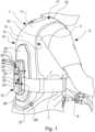
1 ist eine perspektivische Ansicht von hinten und von der rechten Seite, die einen Benutzer (d. h. den Fahrer eines PTW) zeigt, der einen Aufprallschutzairbag gemäß der vorliegenden Erfindung trägt, der in Form einer Weste vorgesehen ist, wobei der Airbag in einem unaufgeblasenen, nicht schützenden Zustand dargestellt ist;2 ist eine perspektivische Ansicht von der linken Seite, dieden Aufprallschutzairbag aus 1 in einem alternativen aufgeblasenen, schützenden Zustand zeigt3 ist eine perspektivische Ansicht von vorne und von der linken Seite, die den Aufprallschutzairbag im aufgeblasenen, schützenden Zustand, wie in2 , zeigt;4 ist eine schematische Darstellung, die ein mögliches Benutzerschnittstellensystem mit einem Smartphone und einer Smartwatch zeigt; und5 ist eine perspektivische Ansicht ähnlich der aus3 , die jedoch eine alternative Ausführungsform des Aufprallschutzairbags mit einer integrierten Handpumpenanordnung zum Aufblasen zeigt.
1 is a rear and right side perspective view showing a user (i.e., the driver of a PTW) wearing an impact protection airbag according to the present invention provided in the form of a vest, the airbag being shown in a deflated, non-protective condition;2 is a perspective view from the left side showing the impact protection airbag from1 in an alternative inflated, protective state3 is a perspective view from the front and left side showing the impact protection airbag in the inflated, protective state as shown in2 , shows;4 is a schematic diagram showing a possible user interface system with a smartphone and a smartwatch; and5 is a perspective view similar to that of3 , which however shows an alternative embodiment of the impact protection airbag with an integrated hand pump arrangement for inflation.
Detaillierte Beschreibung der ErfindungDetailed description of the invention
Nun werden Aspekte und Ausführungsformen der vorliegenden Erfindung unter Bezugnahme auf die beiliegenden Figuren erörtert. Für Fachleute ergeben sich weitere Aspekte und Ausführungsformen.Aspects and embodiments of the present invention will now be discussed with reference to the accompanying figures. Other aspects and embodiments will become apparent to those skilled in the art.
Wie erwähnt, ist der Airbag 1 dazu ausgebildet, sich über den Brustbereich, die Schultern und den Rücken des Benutzers zu erstrecken, und ist mit einer Sicherungsvorrichtung versehen, die einen verstellbaren Hüftgurt 7 umfasst, der es ermöglicht, den vorderen und den hinteren Bereich des Airbags 1 um die Seiten des Torsos 3 des Benutzers zusammenzuziehen, um einen festen und sicheren Sitz zu gewährleisten, wenn der Airbag 1 getragen wird. Der Hüftgurt 7 kann in bekannter Art in der Länge verstellt werden (z. B. durch einen einfachen Klettverschluss), um ihn an Benutzer unterschiedlicher Größen anzupassen. Der Hüftgurt 7 kann aus flexiblem Gurtband geformt sein.As mentioned, the
Der Airbag 1 ist aus einer ersten und einer zweiten übereinanderliegenden Gewebeschicht 8, 9 gebildet, die durch eine Umfangsnaht 10 miteinander verbunden sind, um dazwischen ein aufblasbares Volumen 11 für die Aufnahme von Aufblasluft aus einer Betätigungsanordnung 12 zu definieren. Die Umfangsnaht 10 definiert somit den Umfang des aufblasbaren Volumens 11. Wie zu erkennen ist, ist in den
Wie in den
Der in den
Wie in
In der dargestellten Ausführungsform ist die Betätigungsanordnung 12 in Form einer im Wesentlichen eigenständigen Einheit mit einem Gehäuse 21 vorgesehen, das an dem Aufprallschutzpanel 20 befestigt ist. Die Betätigungsanordnung 12 ist somit in den Airbag 1 integriert, so dass sie vom Benutzer 2 getragen wird, wenn der Airbag 1 in Gebrauch ist (d. h., wenn der Airbag 1 getragen wird).In the illustrated embodiment, the
Die Betätigungsanordnung 12 kann in verschiedenen Formen vorliegen (von denen einige im Folgenden näher beschrieben werden), soll aber vom Benutzer 2 wechselweise (und manuell) betätigt werden können: i) zum Aufblasen des Airbags 1 aus dem unaufgeblasenen, nicht schützenden Zustand, der in
Die Betätigungsanordnung 12 kann betätigt werden, während der Airbag 1 tatsächlich von einem Benutzer 2 getragen wird, um den Airbag zwischen dem oben beschriebenen aufgeblasenen und unaufgeblasenen Zustand aufzublasen und zu entleeren. Es ist daher nicht erforderlich, dass der Benutzer den Airbag 1 vor dem Anlegen aufbläst, und es ist auch nicht erforderlich, den Airbag 1 vor dem Abnehmen zu entleeren. Ferner ist, wie dargestellt, der Airbag 1 in seinem unaufgeblasenen Zustand nicht in eine enge Packung verpackt (z. B. gefaltet und/oder gerollt). Der Airbag 1 kann daher dazu ausgebildet sein, relativ kompakt zu sein. In einigen Ausführungsformen, wie sie in den
Eine Ausführungsform der Betätigungsanordnung 12 wird nun unter besonderer Bezugnahme auf
In der dargestellten Ausführungsform umfasst die Betätigungsanordnung 12 einen elektrisch betriebenen Kompressor 22, der mit einer Stromquelle in Form einer wiederaufladbaren Batterie 23 elektrisch verbunden ist. Der Kompressor 22 und die Batterie 23 sind beide im Gehäuse 21 untergebracht, das in dieser Ausführungsform die Form einer Kompressoreinheit hat. Die Batterie 23 kann in einigen Ausführungsformen von der Kompressoreinheit 21 getrennt werden. Ferner sind andere Ausführungsformen denkbar, bei denen die Kompressoreinheit 21 überhaupt keine Batterie enthält. Beispielsweise könnte die Kompressoreinheit 21 stattdessen mit Mitteln versehen sein, die eine lösbare und elektrische Verbindung zu einer von einem PTW 4 mitgeführten Batterie (z. B. der Zündbatterie des PTW) herstellen, um so den Kompressor 22 zu betreiben. Auf diese Weise kann der Benutzer 2 die Kompressoreinheit 21 vor Antritt einer Fahrt oder Reise elektrisch an die Batterie des PTW anschließen (z. B. durch ein geeignetes elektrisches Kabel) und danach die Kompressoreinheit 21 vom PTW abtrennen. Durch diese Art der Anordnung könnte die Größe der Kompressoreinheit 21 verringert werden.In the illustrated embodiment, the
Der Kompressor 22 verfügt über eine erste Luftstromöffnung (nicht dargestellt), die hinter einer Reihe von kombinierten Luftein- und -auslassöffnungen 24, die durch die hinterste Fläche der Kompressoreinheit 21 hindurchgehen, vorgesehen ist und somit in direkter Fluidverbindung steht. Der Kompressor 22 hat auch eine zweite Luftstromöffnung 25, die in Fluidverbindung mit einem Luftstromdurchlass steht, der sich vom Kompressorgehäuse 21 durch eine Öffnung (nicht dargestellt) im Aufprallschutzpanel 20 und durch eine ausgerichtete Öffnung (ebenfalls nicht dargestellt) erstreckt, die durch den darunter liegenden Bereich, der nach außen weisenden Gewebeschicht 8 des aufblasbaren Rückenpanels 15 gebildet wird. Der Kompressor 22 befindet sich somit in einem effektiven Luftstrompfad, der sich zwischen der Atmosphäre außerhalb des Kompressorgehäuses 21 und dem aufblasbaren Volumen 11 innerhalb des Airbags 1 erstreckt, und zwar über die Einlass-/Auslassöffnungen 24 und die ausgerichteten Öffnungen, die durch das Aufprallschutzpanel 20 und die nach außen gerichtete Gewebeschicht 8 verlaufen.The
Der Kompressor 22 verfügt über eine geeignete, vom Benutzer bedienbare Steuerung, mit der der Benutzer den Kompressor betätigen kann: i) um Aufblasluft aus der Atmosphäre außerhalb des Airbags 1 durch die Einlass-/Auslassöffnungen 24 im Gehäuse 21 und in das aufblasbare Volumen 11 des Airbags 1 zu leiten, um dadurch den Airbag in den in den
Zusätzlich zu der vorstehend beschriebenen Kompressoranordnung kann der Airbag 1 gegebenenfalls auch mit einem Druckablassventil 26 als Teil der Betätigungsanordnung vorgesehen sein. Das Druckablassventil 26 kann entweder durch eine Öffnung 27 in einer der Gewebeschichten 8, 9 des Airbags 1 vorgesehen sein, wie in
Die Kompressoreinheit 21 kann auch eine Steuerung (zum Beispiel eine elektronische Steuereinheit) und einen Drucksensor umfassen, der so angeordnet und ausgebildet ist, dass er den Aufblasdruck in der aufblasbaren Kammer 11 des Airbags 1 misst und ein entsprechendes Drucksignal an die Steuerung bereitstellt.The
Die dargestellte Kompressoreinheit 21 ist auch mit einem primären Benutzerbedienfeld 28 ausgestattet. Ein sekundäres Benutzerbedienfeld 29 kann auch an dem vorderen aufblasbaren Panel 16 des Airbags 1 vorgesehen sein, wie in
Jedes Benutzerbedienfeld 28, 29 verfügt über einen jeweiligen Hauptbetätigungsknopf 31, der vom Benutzer 2 wechselweise betätigt werden kann, um den Airbag 1 in den in den
Neben dem Hauptbetätigungsknopf 31 weist jedes Benutzerbedienfeld 28, 29 auch eine entsprechende Druckanzeige 32 auf. In der speziellen Ausführungsform, die hier gezeigt wird, hat jede Druckanzeige 32 die Form einer Reihe diskreter LEDs und ist dazu ausgebildet, gesteuert durch die Steuerung und in Abhängigkeit von dem vom Drucksensor gelieferten Drucksignal eine optische Anzeige bereitzustellen, die den Aufblasdruck der aufblasbaren Kammer 11 darstellt. Alternativ oder zusätzlich kann jede Druckanzeige 32 dazu ausgebildet sein, eine haptische Anzeige (z. B. durch einen oder mehrere kleine Exzentermotoren) oder einen akustischen Hinweis (z. B. durch einen oder mehrere kleine Lautsprecher) bereitzustellen, die den Aufblasdruck der aufblasbaren Kammer 11 darstellt. Es ist vorgesehen, dass in einigen Ausführungsformen die Druckanzeige 32 so ausgebildet sein kann, dass sie dem Benutzer einen Hinweis darauf gibt, ob der gemessene Aufblasdruck der aufblasbaren Kammer 11 über oder unter einem vorgegebenen Schwellenwert liegt. Wie vorstehend erwähnt, kann der vorgegebene Schwellenwert im Bereich von 40 kPa bis 120 kPa liegen, in einigen Ausführungsformen gegebenenfalls auch bei etwa 80 kPa.In addition to the
In einigen Ausführungsformen ist die Steuerung dazu ausgebildet, den Kompressor 22 in Abhängigkeit (d. h. in Reaktion) auf das vom Drucksensor bereitgestellte Drucksignal aktiv zu steuern und kann dadurch den Aufblasdruck der aufblasbaren Kammer 11 automatisch anpassen, um einen zielgerichteten Aufblasdruck zu erreichen und im Wesentlichen beizubehalten. Der vorgegebene Schwellenwert kann im Bereich von 40 kPa bis 120 kPa liegen, in einigen Ausführungsformen gegebenenfalls auch bei etwa 80 kPa. In solchen Ausführungsformen steuert die Steuerung den Kompressor 22 aktiv, sobald die aufblasbare Kammer 11 im Wesentlichen bis zum aufgeblasenen, schützenden Zustand aufgepumpt ist, so dass: i) Aufblasluft aus der Atmosphäre außerhalb des Airbags 1 durch die Einlass-/Auslassöffnungen 24 im Gehäuse 21 und in das aufblasbare Volumen 11 des Airbags 1 geleitet wird, wenn festgestellt wird, dass der Aufblasdruck unter dem Zielwert liegt, um so den Zielaufblasdruck wiederherzustellen; und ii) Aufblasluft in die entgegengesetzte Richtung aus dem aufblasbaren Volumen 11 innerhalb des Airbags über die Einlass-/Auslassöffnungen 24 in die Atmosphäre geleitet wird, wenn festgestellt wird, dass der Aufblasdruck den Zielwert überschreitet, um dadurch den Zielaufblasdruck wiederherzustellen.In some embodiments, the controller is configured to actively control the
Ferner werden Ausführungsformen der aktiven Steuerung vorgeschlagen, bei denen die Kompressoreinheit 21 ferner ein GPS-Empfängermodul umfassen kann, das ausgebildet ist, um GPS-Daten für die Steuerung bereitzustellen. In solchen Ausführungsformen ist das Steuergerät so ausgebildet, dass es anhand der GPS-Daten die Fahrgeschwindigkeit des Airbags 1 im Gebrauch berechnet (die somit repräsentativ für die Geschwindigkeit des PTW 4 ist) und den Zielaufblasdruck als Reaktion au die berechneten Geschwindigkeit automatisch so anpasst, dass: i) der Zielaufblasdruck als Reaktion auf eine Erhöhung der Geschwindigkeit erhöht wird; und ii) der Zielaufblasdruck als Reaktion auf eine Abnahme der Geschwindigkeit verringert wird. Auf diese Weise kann der Kompressor 22 aktiv gesteuert werden, um den Aufblasdruck der aufblasbaren Kammer 11 während der Fahrt oder Reise mit relativ hoher Geschwindigkeit zu erhöhen (und damit die Festigkeit des Airbags 1 im aufgeblasenen schützenden Zustand zu erhöhen) und den Aufblasdruck während der Fahrt mit niedrigerer Geschwindigkeit zu verringern oder auf ein mittleres Niveau zurückzuführen (und damit die Festigkeit des Airbags 1 im aufgeblasenen, schützenden Zustand zu verringern). Diese Art der Steuerung ermöglicht es, den Airbag 1 während relativ risikoreicher (d. h. schneller) Abschnitte der Fahrt oder Reise auf einen höheren Aufblasdruck und zu anderen Zeiten auf einen niedrigeren Aufblasdruck aufzublasen, was für den Benutzer 2, der den Airbag 1 trägt, angenehmer sein kann.Further embodiments of the active control are proposed in which the
In weiteren Ausführungsformen kann der GPS-Empfänger durch einen Beschleunigungsmesser ergänzt oder ersetzt werden, der so konfiguriert ist, dass er ein Beschleunigungssignal an die Steuerung liefert. In solchen Ausführungsformen ist die Steuerung dazu ausgebildet, den Zielaufblasdruck automatisch zu erhöhen, wenn der Beschleunigungsmesser ein Signal empfängt, das eine Beschleunigung oder Verlangsamung angibt, die einen vorgegebenen Schwellenwert überschreitet (der z. B. als Indikator für einen wahrscheinlichen Unfall angesehen werden kann). Auf diese Weise kann der Kompressor 22 aktiv gesteuert werden, um den Aufblasdruck der aufblasbaren Kammer 11 als direkte Reaktion auf die Erkennung eines potenziell verletzenden Unfalls zu erhöhen, wodurch die Festigkeit des Airbags 1 im aufgeblasenen, schützenden Zustand erhöht wird und somit der Aufprallschutz, der dem Benutzer 2 unter solchen Umständen bereitgestellt wird, verbessert wird.In further embodiments, the GPS receiver may be supplemented or replaced by an accelerometer configured to provide an acceleration signal to the controller. In such embodiments, the controller is configured to automatically increase the target inflation pressure when the accelerometer receives a signal indicating an acceleration or deceleration that exceeds a predetermined threshold (which may, for example, be considered an indicator of a likely accident). In this way, the
Bei Betrachtung von
Rein beispielhaft ist auf dem abgebildeten Smartphone 33 eine laufende App 35 abgebildet, die dem Benutzer 2 verschiedene Symbole mit Informationen zum Systemstatus bereitstellt, umfassend: Verbindungsstatus 36 (d. h. zwischen dem Smartphone 33 und der Kompressoreinheit 21); aktueller Aufblasstatus 37 des Airbags 1 (z. B. „Bereit zum Aufblasen"(„Ready for inflation“), was bedeutet, dass der Airbag gerade unaufgeblasen ist, oder alternativ „Aufgeblasen" („lnflated“), was bedeutet, dass der Airbag 1 aufgeblasen ist); und den Ladezustand der Batterie 38 (d. h. der Batterie 23, die den Kompressor 22 mit Strom versorgt). Ferner zeigt die App 35 verschiedene Symbole an, die Bedienungsknöpfe bezeichnen, durch deren Betätigung verschiedene Betriebsarten der Kompressoreinheit 21 ausgewählt werden können, die zum Beispiel Folgendes umfassen: einen „Geschwindigkeitsabhängigen Modus“ 39 („Speed adaptive mode“, der den Aufblasdruck des Airbags 1 in Abhängigkeit von der Geschwindigkeit steuert, wie oben beschrieben); einen „Leistungsmodus“ 40 („Performance mode“, der zum Beispiel den Aufblasdruck des Airbags 1 in Abhängigkeit von Beschleunigungssignalen eines Beschleunigungsmessers steuern kann, wie vorstehend beschrieben); einen „Stadt“-Modus 41 („City mode“, der zum Beispiel den Zielaufblasdruck auf ein relativ niedriges Niveau einstellen kann); einen „Autobahn“-Modus 42 („Highway mode“, der zum Beispiel den Ziellaufblasdruck auf ein relativ hohes Niveau einstellen kann); und einen „Energiesparmodus“ 43 („Power saving mode“, bei dem zum Beispiel die aktive Steuerung des Kompressors 22 deaktiviert und lediglich ein mittlerer Zielaufblasdruck aufrechterhalten wird).By way of example only, the
Die Smartphone-App 35 zeigt ferner ein Symbol an, das eine Hauptbetätigungstaste 44 darstellt, über die der Benutzer das Aufblasen und Entleeren des Airbags 1 auslösen kann. In dem in
Die Smartwatch-App 36 kann die vorstehend beschriebene Funktionalität und die Symbole der Smartphone-App 35 nachbilden und somit identische Steuerungsfunktionen für den Betrieb der Kompressoreinheit 21 ohne das Smartphone 33 vorsehen. In der in
Obwohl die Erfindung vorstehend unter besonderer Bezugnahme auf verschiedene Ausführungsformen beschrieben wurde, die eine Betätigungsanordnung 12 aufweisen, die einen elektrisch angetriebenen Kompressor 22 umfasst, ist zu beachten, dass dies nicht als wesentlich angesehen wird.
In Ausführungsformen, die eine manuell bedienbare Handpumpe 45 umfassen, kann der Benutzer 2 das oben beschriebene, manuell bedienbare Druckablassventil 26 verwenden, um die Aufblaskammer 11 manuell zu entlüften und dadurch den Airbag 1 zu entleeren. Wie in
Während die Erfindung vorstehend unter besonderer Bezugnahme auf Ausführungsformen beschrieben wurde, die eine um den Torso 3 des Benutzers zu tragende Weste aufweisen, ist anzumerken, dass die Erfindung nicht auf eine solche Anordnung des Airbags beschränkt ist. Zum Beispiel sind alternative Ausführungsformen in Aussicht gestellt, bei denen der Airbag in Form eines Gurtzeugs vorgesehen sein kann; zum Beispiel einen Airbag umfassend, der sich auf jeder Seite der Vorderseite des Torsos eines Benutzers und um den Hals des Benutzers erstreckt, wenn er getragen wird, aber nicht notwendigerweise über den Rücken des Benutzers verläuft. Es sind auch alternative Ausführungsformen in Aussicht gestellt, bei denen der Airbag als Teil einer Schutzjacke, zum Beispiel einer Motorradjacke, vorgesehen ist, zum Beispiel innerhalb der Struktur der Jacke zwischen einem Innenfutter und einer Außenschicht.Whilst the invention has been described above with particular reference to embodiments comprising a vest to be worn around the user's
Die Merkmale, die in der vorstehenden Beschreibung oder in den folgenden Ansprüchen oder in den beigefügten Zeichnungen offenbart sind und die in ihren spezifischen Formen oder in Form eines Mittels zur Erfüllung der offenbarten Funktion oder eines Verfahrens oder eines Prozesses zur Erzielung der offenbarten Ergebnisse ausgedrückt sind, können einzeln oder in einer beliebigen Kombination dieser Merkmale zur Realisierung der Erfindung in verschiedenen Formen verwendet werden.The features disclosed in the foregoing description or in the following claims or in the appended drawings, expressed in their specific forms or in the form of a means for performing the disclosed function or a method or process for achieving the disclosed results, may be used individually or in any combination of these features to realize the invention in various forms.
Obwohl die Erfindung in Verbindung mit den vorstehend beschriebenen beispielhaften Ausführungsformen beschrieben worden ist, ergeben sich für Fachleute bei Lektüre dieser Offenbarung viele gleichwertige Änderungen und Variationen. Dementsprechend werden die oben beschriebenen beispielhaften Ausführungsformen der Erfindung als veranschaulichend und nicht als einschränkend betrachtet. Verschiedene Änderungen an den beschriebenen Ausführungsformen können vorgenommen werden, ohne vom Umfang der Erfindung abzuweichen.Although the invention has been described in connection with the exemplary embodiments described above, many equivalent changes and variations will become apparent to those skilled in the art upon reading this disclosure. Accordingly, the exemplary embodiments of the invention described above are considered to be illustrative and not restrictive. Various changes may be made to the described embodiments without departing from the scope of the invention.
Um jeden Zweifel auszuschließen, dienen alle theoretischen Erläuterungen, die hierin bereitgestellt werden, dem besseren Verständnis der Lesenden. Die Erfinder möchten an keine dieser theoretischen Erklärungen gebunden sein.For the avoidance of doubt, any theoretical explanations provided herein are for the benefit of the reader. The inventors do not intend to be bound by any such theoretical explanations.
Alle hierin verwendeten Abschnittsüberschriften dienen lediglich strukturierendem Zweck und sind nicht als Einschränkung des beschriebenen Gegenstands auszulegen.All section headings used herein are for structuring purposes only and should not be construed as limitations on the subject matter described.
In der gesamten Beschreibung, einschließlich der folgenden Ansprüche, sofern der Kontext nichts anderes erfordert, werden Wörter wie „aufweisen“, „umfassen“ und „einschließen“ und Varianten wie „aufweisend“, „umfasst“, „umfassend“ und „einschließlich“ so verstanden, dass sie die Einbeziehung einer angegebenen ganzen Zahl oder eines Schrittes oder einer Gruppe von ganzen Zahlen oder Schritten implizieren, aber nicht den Ausschluss einer anderen ganzen Zahl oder eines Schrittes oder einer Gruppe von ganzen Zahlen oder Schritten.Throughout the specification, including the claims that follow, unless the context requires otherwise, words such as "comprise," "comprise," and "include," and variants such as "comprising," "comprising," "comprising," and "including" are understood to imply the inclusion of a specified integer or step or group of integers or steps, but not the exclusion of any other integer or step or group of integers or steps.
Es ist zu beachten, dass die Singularformen „ein/eine“ und „der/die/das“, wie sie in der Beschreibung und den beigefügten Ansprüchen verwendet werden, Pluralreferenzen einschließen, es sei denn, der Kontext schreibt eindeutig etwas anderes vor. Bereiche können hierin als von „etwa“ einem bestimmten Wert und/oder bis zu „etwa“ einem anderen bestimmten Wert ausgedrückt werden. Wenn ein solcher Bereich ausgedrückt wird, schließt eine andere Ausführungsform den Bereich von dem einen bestimmten Wert und/oder bis zu dem anderen bestimmten Wert ein. Wenn Werte durch die Verwendung des Bezugsworts „etwa“ als Näherungswerte ausgedrückt werden, versteht es sich, dass der bestimmte Wert eine andere Ausführungsform darstellt. Der Begriff „etwa“ in Bezug auf einen Zahlenwert ist optional und bedeutet z. B. +/- 10 %.It should be noted that the singular forms "a" and "an" and "the" as used in the specification and appended claims include plural references unless the context clearly dictates otherwise. Ranges may be expressed herein as from "about" a particular value and/or up to "about" another particular value. When such a range is expressed, another embodiment includes the range from the one particular value and/or up to the other particular value. When values are expressed as approximate values through the use of the reference word "about," it is understood that the particular value represents another embodiment. The term "about" in reference to a numerical value is optional and means, for example, +/- 10%.
Die Begriffe „bevorzugt“ und „vorzugsweise“ beziehen sich hierin auf Ausführungsformen der Erfindung, die unter bestimmten Umständen bestimmte Vorteile bieten können. Es sei jedoch angemerkt, dass auch andere Ausführungsformen unter den gleichen oder anderen Umständen bevorzugt werden können. Die Erwähnung einer oder mehrerer bevorzugter Ausführungsformen bedeutet oder impliziert daher nicht, dass andere Ausführungsformen nicht nützlich sind, und zielt nicht darauf ab, andere Ausführungsformen vom Umfang der Offenbarung oder vom Umfang der Ansprüche auszuschließen.The terms "preferred" and "preferably" refer herein to embodiments of the invention that may provide particular advantages under certain circumstances. However, it should be noted that other embodiments may also be preferred under the same or different circumstances. Therefore, mention of one or more preferred embodiments does not mean or imply that other embodiments are not useful, and is not intended to exclude other embodiments from the scope of the disclosure or the scope of the claims.
Claims (15)
Translated fromGermanPriority Applications (2)
| Application Number | Priority Date | Filing Date | Title |
|---|---|---|---|
| DE102023116606.9ADE102023116606A1 (en) | 2023-06-23 | 2023-06-23 | PORTABLE IMPACT PROTECTION AIRBAG |
| PCT/EP2024/065148WO2024260708A1 (en) | 2023-06-23 | 2024-06-03 | A wearable impact protection airbag |
Applications Claiming Priority (1)
| Application Number | Priority Date | Filing Date | Title |
|---|---|---|---|
| DE102023116606.9ADE102023116606A1 (en) | 2023-06-23 | 2023-06-23 | PORTABLE IMPACT PROTECTION AIRBAG |
Publications (1)
| Publication Number | Publication Date |
|---|---|
| DE102023116606A1true DE102023116606A1 (en) | 2024-12-24 |
Family
ID=91465417
Family Applications (1)
| Application Number | Title | Priority Date | Filing Date |
|---|---|---|---|
| DE102023116606.9APendingDE102023116606A1 (en) | 2023-06-23 | 2023-06-23 | PORTABLE IMPACT PROTECTION AIRBAG |
Country Status (2)
| Country | Link |
|---|---|
| DE (1) | DE102023116606A1 (en) |
| WO (1) | WO2024260708A1 (en) |
Citations (6)
| Publication number | Priority date | Publication date | Assignee | Title |
|---|---|---|---|---|
| US3771170A (en)* | 1972-07-17 | 1973-11-13 | G Leon | Inflatable insulating material |
| US5546602A (en)* | 1995-10-06 | 1996-08-20 | Hale; Reggie D. | Protective gear |
| US20030106142A1 (en)* | 2001-12-06 | 2003-06-12 | Ingo Raithel | Inflatable insulation incorporating pressure relief means |
| DE102011012026A1 (en)* | 2011-02-22 | 2013-05-08 | Aleksej Limonow | Retainer for driver of e.g. motorized bicycle, has guard sphere which is positioned by surrounding the driver, and safety vest for upper body of driver, that is secured or fastened to backrest |
| US20150327602A1 (en)* | 2014-05-15 | 2015-11-19 | Robert Albin Nelson | Blo-warm vest |
| US20170181482A1 (en)* | 2015-12-28 | 2017-06-29 | Ian A. Bruce | Emergency anti-hypothermia system and highly portable, inflatable emergency vest therefor |
Family Cites Families (3)
| Publication number | Priority date | Publication date | Assignee | Title |
|---|---|---|---|---|
| EP2745720A1 (en)* | 2012-12-18 | 2014-06-25 | Raffaele Pettinato | Protection device |
| WO2016132255A1 (en)* | 2015-02-19 | 2016-08-25 | Giaretta Mattia | Inflatable protection system |
| CN111231884B (en)* | 2020-02-27 | 2021-12-21 | 江苏大学 | Active child airbag vest device and control method thereof |
- 2023
- 2023-06-23DEDE102023116606.9Apatent/DE102023116606A1/enactivePending
- 2024
- 2024-06-03WOPCT/EP2024/065148patent/WO2024260708A1/enactivePending
Patent Citations (6)
| Publication number | Priority date | Publication date | Assignee | Title |
|---|---|---|---|---|
| US3771170A (en)* | 1972-07-17 | 1973-11-13 | G Leon | Inflatable insulating material |
| US5546602A (en)* | 1995-10-06 | 1996-08-20 | Hale; Reggie D. | Protective gear |
| US20030106142A1 (en)* | 2001-12-06 | 2003-06-12 | Ingo Raithel | Inflatable insulation incorporating pressure relief means |
| DE102011012026A1 (en)* | 2011-02-22 | 2013-05-08 | Aleksej Limonow | Retainer for driver of e.g. motorized bicycle, has guard sphere which is positioned by surrounding the driver, and safety vest for upper body of driver, that is secured or fastened to backrest |
| US20150327602A1 (en)* | 2014-05-15 | 2015-11-19 | Robert Albin Nelson | Blo-warm vest |
| US20170181482A1 (en)* | 2015-12-28 | 2017-06-29 | Ian A. Bruce | Emergency anti-hypothermia system and highly portable, inflatable emergency vest therefor |
Also Published As
| Publication number | Publication date |
|---|---|
| WO2024260708A1 (en) | 2024-12-26 |
Similar Documents
| Publication | Publication Date | Title |
|---|---|---|
| DE102006045747B4 (en) | airbag device | |
| DE60116335T2 (en) | MULTIPLE SECURITY CLOTHING FOR MOTORCYCLISTS | |
| DE102016101034B4 (en) | Vehicle oblique impact absorption system | |
| DE19911688B4 (en) | An occupant sensor system and method for sensing an occupant | |
| DE602005002762T2 (en) | Double airbag device | |
| DE602004008899T2 (en) | AIRBAG ARRANGEMENT | |
| DE10315533B4 (en) | Airbag device for a motorcycle | |
| DE10332549A1 (en) | Airbag with ventilation | |
| DE102018104392A1 (en) | Airbag module and vehicle occupant restraint system | |
| DE102018112859A1 (en) | Airbag for front seats mounted on a bulkhead | |
| DE102007029392A1 (en) | Airbag drain with tether | |
| DE202014003584U1 (en) | Inflatable airbag to protect a person, airbag module, vehicle parts and vehicle occupant restraint system with such a gas bag | |
| DE102019119920A1 (en) | AIRBAG FOR RETRACTABLE STEERING WHEEL | |
| DE102017006274B3 (en) | Retaining device for an autonomously operable vehicle | |
| DE102018106009A1 (en) | SIDE ARB WITH FITTING CHAMBER | |
| DE102011116453A1 (en) | Protective helmet for protecting head of wearer from direct contact with e.g. edges, has filling fluid source for accident-initiated filling of inner and outer cavities under resilient expansion of elastic membrane of expansion body | |
| DE602004001528T2 (en) | Child seat. | |
| DE102020133158A1 (en) | A PERSONAL IMPACT PROTECTION SYSTEM | |
| DE19640658C2 (en) | Protective device for users of two-wheeled vehicles | |
| DE102022127848A1 (en) | DISPOSABLE MULTI-CHAMBER AND MULTI-CUSHION AIRBAG | |
| DE102011116444A1 (en) | Safety device e.g. airbag for free seat of e.g. motorcycle, has expansion element which is secured to elastic membrane that is provided for accident-initiated air filling under elastic expansion of the elastic membrane | |
| DE10316766A1 (en) | Protective suit for a motorcyclist, comprises outer airbags and pyrotechnic gas generators where the airbags are folded to form pleats and fastened in strips to the suit by the energy released on inflation | |
| DE102023116606A1 (en) | PORTABLE IMPACT PROTECTION AIRBAG | |
| DE102016107754A1 (en) | Protective suit for motorcyclists | |
| EP1940657B1 (en) | Vehicle seat with a lateral thorax and pelvis airbag fitted to the frame of the seat |
Legal Events
| Date | Code | Title | Description |
|---|---|---|---|
| R012 | Request for examination validly filed | ||
| R016 | Response to examination communication |