DE102023114852A1 - Ultrasonic machining process for joining layers and ultrasonic machining device - Google Patents
Ultrasonic machining process for joining layers and ultrasonic machining deviceDownload PDFInfo
- Publication number
- DE102023114852A1 DE102023114852A1DE102023114852.4ADE102023114852ADE102023114852A1DE 102023114852 A1DE102023114852 A1DE 102023114852A1DE 102023114852 ADE102023114852 ADE 102023114852ADE 102023114852 A1DE102023114852 A1DE 102023114852A1
- Authority
- DE
- Germany
- Prior art keywords
- layer
- sonotrode
- layers
- outer layer
- ultrasonic
- Prior art date
- Legal status (The legal status is an assumption and is not a legal conclusion. Google has not performed a legal analysis and makes no representation as to the accuracy of the status listed.)
- Pending
Links
- 238000003754machiningMethods0.000title2
- 239000000463materialSubstances0.000claimsabstractdescription105
- 238000000034methodMethods0.000claimsabstractdescription29
- 238000007789sealingMethods0.000claimsabstractdescription27
- 238000003672processing methodMethods0.000claimsabstractdescription11
- 230000010355oscillationEffects0.000claimsabstractdescription5
- 238000005096rolling processMethods0.000claimsdescription2
- 238000005304joiningMethods0.000description6
- 239000000853adhesiveSubstances0.000description5
- 230000001070adhesive effectEffects0.000description5
- 239000000047productSubstances0.000description5
- 238000004519manufacturing processMethods0.000description4
- 229920001169thermoplasticPolymers0.000description4
- 239000004416thermosoftening plasticSubstances0.000description4
- 229920000742CottonPolymers0.000description3
- 239000002390adhesive tapeSubstances0.000description3
- 239000000835fiberSubstances0.000description3
- 239000000155meltSubstances0.000description3
- 239000007858starting materialSubstances0.000description3
- 239000002131composite materialSubstances0.000description2
- 230000006835compressionEffects0.000description2
- 238000007906compressionMethods0.000description2
- 239000012141concentrateSubstances0.000description2
- 238000010438heat treatmentMethods0.000description2
- 239000000203mixtureSubstances0.000description2
- 239000011185multilayer composite materialSubstances0.000description2
- 239000007787solidSubstances0.000description2
- 239000012815thermoplastic materialSubstances0.000description2
- 238000002604ultrasonographyMethods0.000description2
- 241001136792AlleSpecies0.000description1
- FGUUSXIOTUKUDN-IBGZPJMESA-NC1(=CC=CC=C1)N1C2=C(NC([C@H](C1)NC=1OC(=NN=1)C1=CC=CC=C1)=O)C=CC=C2Chemical compoundC1(=CC=CC=C1)N1C2=C(NC([C@H](C1)NC=1OC(=NN=1)C1=CC=CC=C1)=O)C=CC=C2FGUUSXIOTUKUDN-IBGZPJMESA-N0.000description1
- 230000002745absorbentEffects0.000description1
- 239000002250absorbentSubstances0.000description1
- 238000005265energy consumptionMethods0.000description1
- 238000005516engineering processMethods0.000description1
- 239000012467final productSubstances0.000description1
- 230000001771impaired effectEffects0.000description1
- 239000013067intermediate productSubstances0.000description1
- 238000002360preparation methodMethods0.000description1
- 230000004936stimulating effectEffects0.000description1
Images

Classifications
- A—HUMAN NECESSITIES
- A61—MEDICAL OR VETERINARY SCIENCE; HYGIENE
- A61F—FILTERS IMPLANTABLE INTO BLOOD VESSELS; PROSTHESES; DEVICES PROVIDING PATENCY TO, OR PREVENTING COLLAPSING OF, TUBULAR STRUCTURES OF THE BODY, e.g. STENTS; ORTHOPAEDIC, NURSING OR CONTRACEPTIVE DEVICES; FOMENTATION; TREATMENT OR PROTECTION OF EYES OR EARS; BANDAGES, DRESSINGS OR ABSORBENT PADS; FIRST-AID KITS
- A61F13/00—Bandages or dressings; Absorbent pads
- A61F13/15—Absorbent pads, e.g. sanitary towels, swabs or tampons for external or internal application to the body; Supporting or fastening means therefor; Tampon applicators
- A61F13/20—Tampons, e.g. catamenial tampons; Accessories therefor
- A61F13/2082—Apparatus or processes of manufacturing
- A61F13/2085—Catamenial tampons
- A61F13/2088—Catamenial tampons shaping the tampon by compressing
- B—PERFORMING OPERATIONS; TRANSPORTING
- B29—WORKING OF PLASTICS; WORKING OF SUBSTANCES IN A PLASTIC STATE IN GENERAL
- B29C—SHAPING OR JOINING OF PLASTICS; SHAPING OF MATERIAL IN A PLASTIC STATE, NOT OTHERWISE PROVIDED FOR; AFTER-TREATMENT OF THE SHAPED PRODUCTS, e.g. REPAIRING
- B29C65/00—Joining or sealing of preformed parts, e.g. welding of plastics materials; Apparatus therefor
- B29C65/02—Joining or sealing of preformed parts, e.g. welding of plastics materials; Apparatus therefor by heating, with or without pressure
- B29C65/08—Joining or sealing of preformed parts, e.g. welding of plastics materials; Apparatus therefor by heating, with or without pressure using ultrasonic vibrations
- B—PERFORMING OPERATIONS; TRANSPORTING
- B29—WORKING OF PLASTICS; WORKING OF SUBSTANCES IN A PLASTIC STATE IN GENERAL
- B29C—SHAPING OR JOINING OF PLASTICS; SHAPING OF MATERIAL IN A PLASTIC STATE, NOT OTHERWISE PROVIDED FOR; AFTER-TREATMENT OF THE SHAPED PRODUCTS, e.g. REPAIRING
- B29C66/00—General aspects of processes or apparatus for joining preformed parts
- B29C66/01—General aspects dealing with the joint area or with the area to be joined
- B29C66/05—Particular design of joint configurations
- B29C66/10—Particular design of joint configurations particular design of the joint cross-sections
- B29C66/11—Joint cross-sections comprising a single joint-segment, i.e. one of the parts to be joined comprising a single joint-segment in the joint cross-section
- B29C66/112—Single lapped joints
- B29C66/1122—Single lap to lap joints, i.e. overlap joints
- B—PERFORMING OPERATIONS; TRANSPORTING
- B29—WORKING OF PLASTICS; WORKING OF SUBSTANCES IN A PLASTIC STATE IN GENERAL
- B29C—SHAPING OR JOINING OF PLASTICS; SHAPING OF MATERIAL IN A PLASTIC STATE, NOT OTHERWISE PROVIDED FOR; AFTER-TREATMENT OF THE SHAPED PRODUCTS, e.g. REPAIRING
- B29C66/00—General aspects of processes or apparatus for joining preformed parts
- B29C66/40—General aspects of joining substantially flat articles, e.g. plates, sheets or web-like materials; Making flat seams in tubular or hollow articles; Joining single elements to substantially flat surfaces
- B29C66/41—Joining substantially flat articles ; Making flat seams in tubular or hollow articles
- B29C66/43—Joining a relatively small portion of the surface of said articles
- B29C66/431—Joining the articles to themselves
- B—PERFORMING OPERATIONS; TRANSPORTING
- B29—WORKING OF PLASTICS; WORKING OF SUBSTANCES IN A PLASTIC STATE IN GENERAL
- B29C—SHAPING OR JOINING OF PLASTICS; SHAPING OF MATERIAL IN A PLASTIC STATE, NOT OTHERWISE PROVIDED FOR; AFTER-TREATMENT OF THE SHAPED PRODUCTS, e.g. REPAIRING
- B29C66/00—General aspects of processes or apparatus for joining preformed parts
- B29C66/70—General aspects of processes or apparatus for joining preformed parts characterised by the composition, physical properties or the structure of the material of the parts to be joined; Joining with non-plastics material
- B29C66/72—General aspects of processes or apparatus for joining preformed parts characterised by the composition, physical properties or the structure of the material of the parts to be joined; Joining with non-plastics material characterised by the structure of the material of the parts to be joined
- B29C66/723—General aspects of processes or apparatus for joining preformed parts characterised by the composition, physical properties or the structure of the material of the parts to be joined; Joining with non-plastics material characterised by the structure of the material of the parts to be joined being multi-layered
- B29C66/7232—General aspects of processes or apparatus for joining preformed parts characterised by the composition, physical properties or the structure of the material of the parts to be joined; Joining with non-plastics material characterised by the structure of the material of the parts to be joined being multi-layered comprising a non-plastics layer
- B29C66/72327—General aspects of processes or apparatus for joining preformed parts characterised by the composition, physical properties or the structure of the material of the parts to be joined; Joining with non-plastics material characterised by the structure of the material of the parts to be joined being multi-layered comprising a non-plastics layer consisting of natural products or their composites, not provided for in B29C66/72321 - B29C66/72324
- B—PERFORMING OPERATIONS; TRANSPORTING
- B29—WORKING OF PLASTICS; WORKING OF SUBSTANCES IN A PLASTIC STATE IN GENERAL
- B29C—SHAPING OR JOINING OF PLASTICS; SHAPING OF MATERIAL IN A PLASTIC STATE, NOT OTHERWISE PROVIDED FOR; AFTER-TREATMENT OF THE SHAPED PRODUCTS, e.g. REPAIRING
- B29C66/00—General aspects of processes or apparatus for joining preformed parts
- B29C66/70—General aspects of processes or apparatus for joining preformed parts characterised by the composition, physical properties or the structure of the material of the parts to be joined; Joining with non-plastics material
- B29C66/73—General aspects of processes or apparatus for joining preformed parts characterised by the composition, physical properties or the structure of the material of the parts to be joined; Joining with non-plastics material characterised by the intensive physical properties of the material of the parts to be joined, by the optical properties of the material of the parts to be joined, by the extensive physical properties of the parts to be joined, by the state of the material of the parts to be joined or by the material of the parts to be joined being a thermoplastic or a thermoset
- B29C66/739—General aspects of processes or apparatus for joining preformed parts characterised by the composition, physical properties or the structure of the material of the parts to be joined; Joining with non-plastics material characterised by the intensive physical properties of the material of the parts to be joined, by the optical properties of the material of the parts to be joined, by the extensive physical properties of the parts to be joined, by the state of the material of the parts to be joined or by the material of the parts to be joined being a thermoplastic or a thermoset characterised by the material of the parts to be joined being a thermoplastic or a thermoset
- B29C66/7392—General aspects of processes or apparatus for joining preformed parts characterised by the composition, physical properties or the structure of the material of the parts to be joined; Joining with non-plastics material characterised by the intensive physical properties of the material of the parts to be joined, by the optical properties of the material of the parts to be joined, by the extensive physical properties of the parts to be joined, by the state of the material of the parts to be joined or by the material of the parts to be joined being a thermoplastic or a thermoset characterised by the material of the parts to be joined being a thermoplastic or a thermoset characterised by the material of at least one of the parts being a thermoplastic
- B—PERFORMING OPERATIONS; TRANSPORTING
- B29—WORKING OF PLASTICS; WORKING OF SUBSTANCES IN A PLASTIC STATE IN GENERAL
- B29C—SHAPING OR JOINING OF PLASTICS; SHAPING OF MATERIAL IN A PLASTIC STATE, NOT OTHERWISE PROVIDED FOR; AFTER-TREATMENT OF THE SHAPED PRODUCTS, e.g. REPAIRING
- B29C66/00—General aspects of processes or apparatus for joining preformed parts
- B29C66/70—General aspects of processes or apparatus for joining preformed parts characterised by the composition, physical properties or the structure of the material of the parts to be joined; Joining with non-plastics material
- B29C66/74—Joining plastics material to non-plastics material
- B29C66/748—Joining plastics material to non-plastics material to natural products or their composites, not provided for in groups B29C66/742 - B29C66/746
- B29C66/7485—Natural fibres, e.g. wool, cotton
- B—PERFORMING OPERATIONS; TRANSPORTING
- B29—WORKING OF PLASTICS; WORKING OF SUBSTANCES IN A PLASTIC STATE IN GENERAL
- B29C—SHAPING OR JOINING OF PLASTICS; SHAPING OF MATERIAL IN A PLASTIC STATE, NOT OTHERWISE PROVIDED FOR; AFTER-TREATMENT OF THE SHAPED PRODUCTS, e.g. REPAIRING
- B29C66/00—General aspects of processes or apparatus for joining preformed parts
- B29C66/80—General aspects of machine operations or constructions and parts thereof
- B29C66/81—General aspects of the pressing elements, i.e. the elements applying pressure on the parts to be joined in the area to be joined, e.g. the welding jaws or clamps
- B29C66/814—General aspects of the pressing elements, i.e. the elements applying pressure on the parts to be joined in the area to be joined, e.g. the welding jaws or clamps characterised by the design of the pressing elements, e.g. of the welding jaws or clamps
- B29C66/8141—General aspects of the pressing elements, i.e. the elements applying pressure on the parts to be joined in the area to be joined, e.g. the welding jaws or clamps characterised by the design of the pressing elements, e.g. of the welding jaws or clamps characterised by the surface geometry of the part of the pressing elements, e.g. welding jaws or clamps, coming into contact with the parts to be joined
- B29C66/81431—General aspects of the pressing elements, i.e. the elements applying pressure on the parts to be joined in the area to be joined, e.g. the welding jaws or clamps characterised by the design of the pressing elements, e.g. of the welding jaws or clamps characterised by the surface geometry of the part of the pressing elements, e.g. welding jaws or clamps, coming into contact with the parts to be joined comprising a single cavity, e.g. a groove
- B—PERFORMING OPERATIONS; TRANSPORTING
- B29—WORKING OF PLASTICS; WORKING OF SUBSTANCES IN A PLASTIC STATE IN GENERAL
- B29C—SHAPING OR JOINING OF PLASTICS; SHAPING OF MATERIAL IN A PLASTIC STATE, NOT OTHERWISE PROVIDED FOR; AFTER-TREATMENT OF THE SHAPED PRODUCTS, e.g. REPAIRING
- B29C66/00—General aspects of processes or apparatus for joining preformed parts
- B29C66/80—General aspects of machine operations or constructions and parts thereof
- B29C66/83—General aspects of machine operations or constructions and parts thereof characterised by the movement of the joining or pressing tools
- B29C66/832—Reciprocating joining or pressing tools
- B29C66/8322—Joining or pressing tools reciprocating along one axis
- B—PERFORMING OPERATIONS; TRANSPORTING
- B29—WORKING OF PLASTICS; WORKING OF SUBSTANCES IN A PLASTIC STATE IN GENERAL
- B29C—SHAPING OR JOINING OF PLASTICS; SHAPING OF MATERIAL IN A PLASTIC STATE, NOT OTHERWISE PROVIDED FOR; AFTER-TREATMENT OF THE SHAPED PRODUCTS, e.g. REPAIRING
- B29C66/00—General aspects of processes or apparatus for joining preformed parts
- B29C66/80—General aspects of machine operations or constructions and parts thereof
- B29C66/83—General aspects of machine operations or constructions and parts thereof characterised by the movement of the joining or pressing tools
- B29C66/836—Moving relative to and tangentially to the parts to be joined, e.g. transversely to the displacement of the parts to be joined, e.g. using a X-Y table
- B—PERFORMING OPERATIONS; TRANSPORTING
- B29—WORKING OF PLASTICS; WORKING OF SUBSTANCES IN A PLASTIC STATE IN GENERAL
- B29C—SHAPING OR JOINING OF PLASTICS; SHAPING OF MATERIAL IN A PLASTIC STATE, NOT OTHERWISE PROVIDED FOR; AFTER-TREATMENT OF THE SHAPED PRODUCTS, e.g. REPAIRING
- B29C66/00—General aspects of processes or apparatus for joining preformed parts
- B29C66/90—Measuring or controlling the joining process
- B29C66/95—Measuring or controlling the joining process by measuring or controlling specific variables not covered by groups B29C66/91 - B29C66/94
- B29C66/951—Measuring or controlling the joining process by measuring or controlling specific variables not covered by groups B29C66/91 - B29C66/94 by measuring or controlling the vibration frequency and/or the vibration amplitude of vibrating joining tools, e.g. of ultrasonic welding tools
- B29C66/9517—Measuring or controlling the joining process by measuring or controlling specific variables not covered by groups B29C66/91 - B29C66/94 by measuring or controlling the vibration frequency and/or the vibration amplitude of vibrating joining tools, e.g. of ultrasonic welding tools characterised by specific vibration amplitude values or ranges
- B—PERFORMING OPERATIONS; TRANSPORTING
- B29—WORKING OF PLASTICS; WORKING OF SUBSTANCES IN A PLASTIC STATE IN GENERAL
- B29K—INDEXING SCHEME ASSOCIATED WITH SUBCLASSES B29B, B29C OR B29D, RELATING TO MOULDING MATERIALS OR TO MATERIALS FOR MOULDS, REINFORCEMENTS, FILLERS OR PREFORMED PARTS, e.g. INSERTS
- B29K2711/00—Use of natural products or their composites, not provided for in groups B29K2601/00 - B29K2709/00, for preformed parts, e.g. for inserts
- B29K2711/10—Natural fibres, e.g. wool or cotton
- B—PERFORMING OPERATIONS; TRANSPORTING
- B29—WORKING OF PLASTICS; WORKING OF SUBSTANCES IN A PLASTIC STATE IN GENERAL
- B29L—INDEXING SCHEME ASSOCIATED WITH SUBCLASS B29C, RELATING TO PARTICULAR ARTICLES
- B29L2031/00—Other particular articles
- B29L2031/48—Wearing apparel
- B29L2031/4871—Underwear
- B29L2031/4878—Diapers, napkins
Landscapes
- Engineering & Computer Science (AREA)
- Mechanical Engineering (AREA)
- Health & Medical Sciences (AREA)
- Chemical & Material Sciences (AREA)
- Composite Materials (AREA)
- Heart & Thoracic Surgery (AREA)
- Epidemiology (AREA)
- Biomedical Technology (AREA)
- Manufacturing & Machinery (AREA)
- Vascular Medicine (AREA)
- Life Sciences & Earth Sciences (AREA)
- Animal Behavior & Ethology (AREA)
- General Health & Medical Sciences (AREA)
- Public Health (AREA)
- Veterinary Medicine (AREA)
- Lining Or Joining Of Plastics Or The Like (AREA)
Abstract
Translated fromGerman
Description
Translated fromGermanDie vorliegende Erfindung betrifft ein Ultraschallbearbeitungsverfahren zur Verbindung von Schichten eines kompressiblen Materials sowie eine Ultraschallbearbeitungsvorrichtung zur Durchführung des Verfahrens.The present invention relates to an ultrasonic processing method for joining layers of a compressible material and to an ultrasonic processing device for carrying out the method.
Unter Kompression wird die Verringerung des Volumens und damit eine Erhöhung der Dichte eines Körpers verstanden, wenn dieser aus einer oder mehreren Richtungen zusammengedrückt, d.h. wenn eine Kraft auf den Körper ausgeübt wird. Im Allgemeinen kann daher jeder Festkörper als kompressibel angenommen werden, sofern ein genügend hoher Druck auf den Festkörper ausgeübt wird.Compression is the reduction in volume and thus an increase in density of a body when it is compressed from one or more directions, i.e. when a force is exerted on the body. In general, any solid body can therefore be considered compressible, provided that a sufficiently high pressure is exerted on the solid body.
Unter kompressiblen Materialien im Sinne der vorliegenden Erfindung werden jedoch insbesondere Materialien verstanden, deren Volumen und damit deren Dichte durch ein Zusammendrücken des Materials leicht veränderbar ist. Hierzu zählen beispielsweise lose Gefüge aus Fasern oder Fäden wie Watte oder schwammartige Materialien, die sich durch einen hohen Luftanteil auszeichnen und damit ein niedriges Kompressionsmodul < 0,01GPa aufweisen.However, compressible materials in the sense of the present invention are understood to mean in particular materials whose volume and thus their density can be easily changed by compressing the material. These include, for example, loose structures made of fibers or threads such as cotton wool or spongy materials that are characterized by a high air content and thus have a low compression modulus < 0.01 GPa.
Für die Bearbeitung dieser kompressiblen Materialien kommen zunehmend Ultraschallbearbeitungsverfahren zum Einsatz, um z.B. Hygieneprodukte wie Windeln oder Tampons herzustellen. Dazu wird eine Ultraschallschwingung mithilfe einer Sonotrode in das Material eingebracht, wodurch es zu einer lokal begrenzten Erwärmung des Materials kommt. Durch die Erwärmung werden die Bestandteile des Materials wie Fasern oder Fäden in ihrer Zusammensetzung verändert, sodass beispielsweise einzelne Schichten eines Materials miteinander verbunden werden können oder das Material in eine bestimmte Form gebracht wird.Ultrasonic processing methods are increasingly being used to process these compressible materials, for example to produce hygiene products such as diapers or tampons. To do this, an ultrasonic vibration is introduced into the material using a sonotrode, which causes the material to be heated locally. The heating changes the composition of the components of the material, such as fibers or threads, so that, for example, individual layers of a material can be connected to one another or the material can be shaped into a specific form.
Bei den beschriebenen Herstellungs- und Bearbeitungsverfahren mittels Ultraschall werden die kompressiblen Materialien typischerweise in Form von aufgerollten Materialbahnen der Bearbeitungsvorrichtung zugeführt oder zu einem Zwischen- oder Endprodukt aufgerollt. Dabei können auch unterschiedliche Materialbahnen der Bearbeitungsvorrichtung gleichzeitig zugeführt werden oder für die Zuführung miteinander verbunden werden. Wird das Bearbeitungsverfahren unterbrochen, etwa weil Materialien oder Werkzeuge ausgewechselt werden müssen, muss die Materialbahn gegen ein weiteres Abrollen gesichert werden. Zu diesem Zweck ist aus dem einschlägigen Stand der Technik bisher nur bekannt, die noch aufgerollte Materialbahn mit einem Klebeband oder einem anderen Klebemittel zu verschließen.In the described manufacturing and processing methods using ultrasound, the compressible materials are typically fed to the processing device in the form of rolled-up material webs or rolled up into an intermediate or final product. Different material webs can also be fed to the processing device at the same time or connected to one another for feeding. If the processing process is interrupted, for example because materials or tools have to be replaced, the material web must be secured against further unrolling. For this purpose, the only known method from the relevant state of the art is to seal the still rolled-up material web with an adhesive tape or other adhesive.
Dies stellt jedoch einen zusätzlichen Schritt im Bearbeitungsprozess dar, der mit einem hohen Personalbedarf und einer entsprechenden Präparationszeit einhergeht. Zudem führt die Verwendung eines Klebebandes zu zusätzlichen Materialkosten und reduziert die Nachhaltigkeit des Bearbeitungsprozesses bzw. des hergestellten Produktes. Die verwendeten Klebstoffe sind vor allem in Hygieneprodukten unerwünscht.However, this represents an additional step in the processing process, which requires a lot of personnel and a corresponding preparation time. In addition, the use of an adhesive tape leads to additional material costs and reduces the sustainability of the processing process or the manufactured product. The adhesives used are undesirable, especially in hygiene products.
Ein Verschließen von aufgerollten Materialbahnen ist auch bei der Herstellung von z.B. Toilettenpapierrollen erforderlich. In diesem technischen Bereich erfolgt der Verschluss der Rollen zurzeit durch eine thermische Siegelung. Eine Übertragung dieser Technik auf Ultraschallbearbeitungsverfahren würde jedoch ein zusätzliches Werkzeug in der Ultraschallbearbeitungsvorrichtung erfordern. Des Weiteren ist die thermische Siegelung mit hohen Energiekosten verbunden und beeinträchtigt die Qualität des Produktes sowie die Prozessstabilität.Sealing rolled up material webs is also necessary in the production of toilet paper rolls, for example. In this technical area, the rolls are currently sealed using thermal sealing. However, transferring this technology to ultrasonic processing methods would require an additional tool in the ultrasonic processing device. Furthermore, thermal sealing is associated with high energy costs and impairs the quality of the product and the process stability.
Dieser Nachteil der thermischen Siegelung findet sich beispielsweise auch in der Herstellung von Tampons und anderen absorbierenden, mehrlagigen Hygieneartikeln, die in eine bestimmte Form gebracht werden sollen.This disadvantage of thermal sealing can also be found, for example, in the production of tampons and other absorbent, multi-layered hygiene products that need to be shaped into a specific form.
Der vorliegenden Erfindung liegt daher die Aufgabe zugrunde ein Ultraschallbearbeitungsverfahren zum Verbinden von Schichten eines kompressiblen Materials bzw. eine entsprechende Vorrichtung bereitzustellen, mit welchen die Schichten ohne zusätzliche Klebemittel oder zusätzliche Werkzeuge für eine thermische Siegelung verbunden werden können.The present invention is therefore based on the object of providing an ultrasonic processing method for joining layers of a compressible material or a corresponding device with which the layers can be joined without additional adhesives or additional tools for thermal sealing.
Die der Erfindung zugrunde liegende Aufgabe wird durch ein Ultraschallbearbeitungsverfahren der eingangs genannten Art gelöst, wobei das Verfahren die folgenden Schritte aufweist:
- a. Bereitstellen von zumindest drei aufeinander angeordneten Schichten eines Materials oder verschiedener Materialien, nämlich einer äußeren Schicht, einer inneren Schicht und zumindest einer zwischen der äußeren Schicht und der inneren Schicht angeordneten mittleren Schicht, wobei zumindest eine der zumindest drei Schichten ein kompressibles Material aufweist,
- b. Bereitstellen einer Sonotrode mit einer Siegelfläche, wobei die Sonotrode dafür vorgesehen ist, mit einer Ultraschallschwingung in Resonanz gebracht zu werden,
- c. Inkontaktbringen der Siegelfläche mit der äußeren Schicht und Bewegen der Sonotrode in Richtung der inneren Schicht mit einer Zustellkraft, sodass die aufeinander angeordneten Schichten durch die Zustellkraft zusammengedrückt werden,
- d. Anregen der Sonotrode mit der Ultraschallschwingung,
- a. Providing at least three layers of one material or different materials arranged on top of one another, namely an outer layer, an inner layer and at least one middle layer arranged between the outer layer and the inner layer, wherein at least one of the at least three layers comprises a compressible material,
- b. Providing a sonotrode with a sealing surface, wherein the sonotrode is intended to be brought into resonance with an ultrasonic vibration,
- c. Bringing the sealing surface into contact with the outer layer and moving the sonotrode towards the inner layer with a feed force so that the superimposed ten layers are compressed by the delivery force,
- d. Stimulating the sonotrode with the ultrasonic vibration,
Das erfindungsgemäße Verfahren bietet den Vorteil, dass die Bearbeitung von kompressiblen Materialien etwa zum Verschluss einer aufgerollten Materialbahn oder zur Herstellung eines Tampons automatisiert wird und kein manueller Einsatz oder zusätzliche energieintensive Werkzeuge mehr notwendig sind. Dadurch entfällt auch die bisherige Notwendigkeit zusätzlicher Verbrauchsmaterialien wie etwa Klebeband oder zusätzlicher Werkzeuge.The method according to the invention offers the advantage that the processing of compressible materials, for example for closing a rolled-up material web or for producing a tampon, is automated and manual use or additional energy-intensive tools are no longer necessary. This also eliminates the previous need for additional consumables such as adhesive tape or additional tools.
Vorzugsweise werden nur die äußere Schicht und die unmittelbar an die äußere Schicht angrenzende mittlere Schicht miteinander verbunden, sodass die darunterliegenden Schichten durch die Ultraschallbearbeitung nicht beinträgt werden.Preferably, only the outer layer and the middle layer immediately adjacent to the outer layer are bonded together so that the underlying layers are not affected by the ultrasonic processing.
Es versteht sich, dass in einer Ausführungsform die aufeinander angeordneten Schichten durch Aufrollen einer Materialbahn aus dem Material bereitgestellt werden. Alternativ oder zusätzlich können die aufeinander angeordneten Schichten auch durch Falten einer Materialbahn gebildet werden.It is understood that in one embodiment, the layers arranged on top of one another are provided by rolling up a web of material. Alternatively or additionally, the layers arranged on top of one another can also be formed by folding a web of material.
In einer weiteren Ausführungsform können die aufeinander angeordneten Schichten auch durch unterschiedliche kompressible bzw. nicht-kompressible Materialien bereitgestellt werden. Eine Schicht kann außerdem aus mehreren Unterschichten bestehen, die vorzugsweise bereits miteinander verbunden sind.In a further embodiment, the layers arranged on top of one another can also be provided by different compressible or non-compressible materials. A layer can also consist of several sub-layers, which are preferably already connected to one another.
In einer Ausführungsform des Verfahren wird daher ein mehrschichtiges Material mit einer kompressiblen Schicht und einer folienartigen Schicht bereitgestellt, wobei die folienartige Schicht über die kompressible Schicht in zumindest einer Richtung hervorsteht und das mehrschichtige Material derart aufgerollt wird, dass die kompressible Schicht die innere Schicht bereitstellt und die folienartige Schicht im Bereich einer Überlappung die mittlere Schicht und die äußere Schicht bereitstellt.In one embodiment of the method, a multilayer material is therefore provided with a compressible layer and a film-like layer, wherein the film-like layer protrudes beyond the compressible layer in at least one direction and the multilayer material is rolled up such that the compressible layer provides the inner layer and the film-like layer provides the middle layer and the outer layer in the region of an overlap.
Zur Herstellung eines Tampons werden der Bearbeitungsvorrichtung beispielsweise mehrlagige Materialbahnen zugeführt, die sich aus unterschiedlichen Materialien zusammensetzen, aufgerollt und in eine bestimmte Form, z.B. eine Tamponform, verpresst werden. Damit sich die Lagen nicht wieder lösen, werden die obersten Lagen der aufgerollten Materialbahn mittels Ultraschall miteinander verbunden. Dies bietet den Vorteil, dass weder gesundheitsgefährdende Klebstoffe zum Einsatz kommen noch ein zusätzliches Werkzeug zur thermischen Siegelung erforderlich ist. Die Oberfläche des Tampons wird durch die Ultraschallbearbeitung weniger beeinträchtigt als durch die thermische Siegelung und bietet daher einen höheren Tragekomfort.To produce a tampon, for example, multi-layered material webs made up of different materials are fed to the processing device, rolled up and pressed into a specific shape, e.g. a tampon shape. To prevent the layers from coming apart again, the top layers of the rolled-up material web are bonded together using ultrasound. This offers the advantage that neither health-endangering adhesives are used nor is an additional tool required for thermal sealing. The surface of the tampon is less affected by ultrasonic processing than by thermal sealing and is therefore more comfortable to wear.
Bei den übereinander angeordneten Materialien kann es sich also um gleiche Materialien oder um unterschiedliche Materialien handeln, wobei zumindest eine der Materiallagen ein kompressibles Material aufweist. Die Materialien einer Lage können dabei aus einem Gemisch thermoplastischer und nicht-thermoplastischer Fasern bestehen oder eine der Lagen aus thermoplastischen Material, während eine anderen Lage aus nicht-thermoplastischen Material besteht. Bei der Tamponherstellung kommen mehrschichtige Verbundmaterialien zum Einsatz, die beispielsweise aus einer thermoplastischen äußeren Folie sowie innenliegenden, kompressiblen Watteschichten bestehen. Werden diese Verbundmaterialien aufgerollt, umschließt die äußere thermoplastische Folie die innenliegenden, kompressiblen Watteschichten.The materials arranged on top of each other can be the same or different materials, with at least one of the material layers comprising a compressible material. The materials of one layer can consist of a mixture of thermoplastic and non-thermoplastic fibers, or one of the layers can consist of thermoplastic material while another layer consists of non-thermoplastic material. Multi-layer composite materials are used in tampon production, which consist, for example, of a thermoplastic outer film and inner, compressible cotton layers. If these composite materials are rolled up, the outer thermoplastic film encloses the inner, compressible cotton layers.
Insbesondere übt das kompressible Material eine Rückstellkraft auf die Sonotrode aus, die der Zustellkraft entgegenwirkt. In einer Ausführungsform wird das kompressible Material derart gewählt, dass durch die Rückstellkraft eine für das Verbinden der Schichten erforderliche Gegenkraft bereitgestellt wird. Das kompressible Material bringt also der Sonotrode von sich aus eine ausreichende Kraft entgegen, die für ein Verbinden der äußeren Schicht mit der angrenzenden mittleren Schicht ausreicht.In particular, the compressible material exerts a restoring force on the sonotrode that counteracts the feed force. In one embodiment, the compressible material is selected such that the restoring force provides a counterforce required to connect the layers. The compressible material therefore applies sufficient force to the sonotrode on its own, which is sufficient to connect the outer layer to the adjacent middle layer.
In einer weiteren bevorzugten Ausführungsform wird das Verfahren daher ohne zusätzliches Gegenwerkzeug als Energierichtungsgeber ausgeführt. Unter einem Energierichtungsgeber werden im Sinne der vorliegenden Erfindung Komponenten der Ultraschallbearbeitungsvorrichtung oder des zu bearbeitenden Materials verstanden, die die in das Material einzubringende oder eingebrachte Ultraschallenergie auf einen definierten Fügebereich zwischen der äußeren und der mittleren Schicht fokussieren. Durch diese Energiefokussierung ist die Wärmeentwicklung in dem definierten Fügebereich am größten. Es wird eine stabile Verbindung bei möglichst geringem Energieverbrauch erzielt. Beispielsweise handelt es sich bei einer Sonotrode, die die Ultraschallschwingung zielgerichtet in das Material einbringt, um einen Energierichtungsgeber. Insbesondere kann die Sonotrode hierzu bestimmte Formen aufweisen.In a further preferred embodiment, the method is therefore carried out without an additional counter tool as an energy director. In the context of the present invention, an energy director is understood to mean components of the ultrasonic processing device or of the material to be processed that focus the ultrasonic energy to be introduced or introduced into the material on a defined joining area between the outer and middle layers. This energy focusing means that the heat development is greatest in the defined joining area. A stable connection is achieved with the lowest possible energy consumption. For example, a sonotrode that introduces the ultrasonic vibration into the material in a targeted manner is an energy director. In particular, the sonotrode can have certain shapes for this purpose.
Bei aus dem Stand der Technik bekannten Verfahren ist gegenüberliegend zu der Sonotrode ein Gegenwerkzeug, beispielsweise in Form einer Walze, angeordnet, sodass das zu bearbeitende Material in einem Spalt zwischen Sonotrode und Gegenwerkzeug angeordnet ist und das Gegenwerkzeug als zweiter Energierichtungsgeber die Ultraschallenergie ebenfalls im Fügebereich konzentriert.In methods known from the prior art, a counter tool, for example in the form of a roller, is arranged opposite the sonotrode, so that the material to be processed is arranged in a gap between the sonotrode and the counter tool and the counter tool, as a second energy director, also concentrates the ultrasonic energy in the joining area.
Erfindungsgemäß fungiert jedoch das kompressible Material an sich als zweiter Energierichtungsgeber, um die Ultraschallenergie im Fügebereich zwischen äußerer und mittlerer Schicht zu konzentrieren. Durch den Wegfall eines Gegenwerkzeuges im eigentlichen Sinn können die Kosten des Bearbeitungsverfahrens deutlich reduziert werden. Es versteht sich, dass etwaige Halte- oder Positionierungsvorrichtungen, die der Halterung oder Positionierung der aufeinander angeordneten Schichten dienen, kein Gegenwerkzeug in Sinne eines Energierichtungsgebers darstellen, da die in das Material eingebrachte Ultraschallenergie durch diese mechanischen Komponenten nicht auf den Fügebereich fokussiert wird. Derartige Halte- oder Positionierungsvorrichtungen dienen ausschließlich der Halterung oder Positionierung der zu bearbeitenden Materialien, tragen selbst aber nicht zur Ultraschallbearbeitung bei.According to the invention, however, the compressible material itself acts as a second energy director to concentrate the ultrasonic energy in the joining area between the outer and middle layers. By eliminating a counter tool in the true sense, the costs of the processing method can be significantly reduced. It goes without saying that any holding or positioning devices that serve to hold or position the layers arranged on top of one another do not represent a counter tool in the sense of an energy director, since the ultrasonic energy introduced into the material is not focused on the joining area by these mechanical components. Such holding or positioning devices serve exclusively to hold or position the materials to be processed, but do not themselves contribute to the ultrasonic processing.
In einer weiteren Ausführungsform ist die in Schritt d. erzeugte Verbindung zwischen der äußeren Schicht und der zumindest einen mittleren Schicht eine punktuelle oder linienförmige Verbindung. Durch die punktuelle oder linienförmige, d.h. nicht flächige Verbindung wird sichergestellt, dass beispielsweise ein selbstständiges Abrollen der Materialbahn verhindert, das kompressible Material an sich aber so wenig wie möglich bearbeitet wird. Insbesondere ist die Verbindung zwischen der äußeren Schicht und der angrenzenden mittleren Schicht lösbar ausgestaltet, sodass bei Wiederaufnahme der Ultraschallbearbeitung die Materialbahn leicht geöffnet werden kann. Es versteht sich, dass die punktuelle Verbindung nicht auf kreisförmige Verbindungspunkte beschränkt ist, sondern hierunter auch andere geometrische Formen wie Dreiecke, Rechtecke etc. fallen.In a further embodiment, the connection created in step d. between the outer layer and the at least one middle layer is a point-like or linear connection. The point-like or linear, i.e. non-flat, connection ensures that, for example, the material web is prevented from unrolling on its own, but the compressible material itself is processed as little as possible. In particular, the connection between the outer layer and the adjacent middle layer is designed to be detachable, so that the material web can be easily opened when ultrasonic processing is resumed. It goes without saying that the point-like connection is not limited to circular connection points, but also includes other geometric shapes such as triangles, rectangles, etc.
In einer Ausführungsform weist die Ultraschallschwingung, mit welcher die Sonotrode in Schritt d. angeregt wird, eine Frequenz von mindestens 20 kHz und höchstens 35 kHz auf. Bei diesen Frequenzen ist sichergestellt, dass es zu einer ausreichenden Bearbeitung des Materials kommt, das Material gleichzeitig aber nicht unnötig in seiner Struktur beeinträchtigt wird.In one embodiment, the ultrasonic vibration with which the sonotrode is excited in step d. has a frequency of at least 20 kHz and at most 35 kHz. At these frequencies, it is ensured that the material is sufficiently processed, but at the same time the material's structure is not unnecessarily impaired.
In einer weiteren Ausführungsform weist die Ultraschallschwingung, mit welcher die Sonotrode in Schritt d. angeregt wird, eine Amplitude von mindestens 5 µm, vorzugsweise von mindestens 10 µm und besonders bevorzugt von mindestens 15 µm auf. Unter der Amplitude der Ultraschallschwingung wird eine Maximalamplitude verstanden, die zwischen der Ruhelage der Sonotrode und der maximalen Expansion der Sonotrode definiert wird. Durch die Wahl der Schwingungsamplitude wird sichergestellt, dass das kompressible Material in ausreichender Form zusätzlich zu der Zustellkraft zusammengedrückt wird und damit die Gegenkraft des Materials für das Verbinden der Schichten erhöht wird, sodass letztlich die Verbindungstabilität erhöht wird.In a further embodiment, the ultrasonic vibration with which the sonotrode is excited in step d. has an amplitude of at least 5 µm, preferably of at least 10 µm and particularly preferably of at least 15 µm. The amplitude of the ultrasonic vibration is understood to be a maximum amplitude that is defined between the rest position of the sonotrode and the maximum expansion of the sonotrode. The choice of the vibration amplitude ensures that the compressible material is compressed sufficiently in addition to the feed force and thus the counterforce of the material for connecting the layers is increased, so that ultimately the connection stability is increased.
In einer weiteren Ausführungsform rotiert die Sonotrode während Schritt f. um eine Rotationsachse, wobei die Rotationsachse senkrecht zu einer Richtung der Zustellkraft ausgerichtet ist. Eine rotierende Sonotrode kann gleichzeitig als Materialführungswalze für das kompressible Material genutzt werden.In a further embodiment, the sonotrode rotates about a rotation axis during step f., wherein the rotation axis is aligned perpendicular to a direction of the feed force. A rotating sonotrode can simultaneously be used as a material guide roller for the compressible material.
In einer Ausführungsform wird die Siegelfläche auf das zu bearbeitende kompressible Material abgestimmt. Je nach Material ist die Siegelfläche in einer Ausführungsform glatt oder strukturiert. Im Falle einer strukturierten Siegelfläche weist die Siegelfläche vorzugsweise zumindest einen Schlitz und/oder punktuelle Erhebungen und/oder eine Wabenstruktur auf. Durch die strukturierte Siegelfläche wird ein gezielter Energieeintrag in das kompressible Material ermöglicht. Insbesondere der Schlitz bietet einen Flusskanal für die Schmelze, die bei der Erwärmung des Materials entsteht, sodass die Schmelze gezielt an der Materialoberfläche geleitet wird.In one embodiment, the sealing surface is tailored to the compressible material to be processed. Depending on the material, the sealing surface is smooth or structured in one embodiment. In the case of a structured sealing surface, the sealing surface preferably has at least one slot and/or point-like elevations and/or a honeycomb structure. The structured sealing surface enables targeted energy input into the compressible material. The slot in particular provides a flow channel for the melt that is created when the material is heated, so that the melt is directed in a targeted manner along the material surface.
Insbesondere ist der Schlitz in einer Ausführungsform vorzugsweise nicht in einer Vorschubrichtung orientiert, in welcher die aufeinander angeordneten Schichten des kompressiblen Materials relativ zu der Sonotrode bewegt werden.In particular, in one embodiment, the slot is preferably not oriented in a feed direction in which the layers of the compressible material arranged on top of one another are moved relative to the sonotrode.
In einer weiteren Ausführungsform ist die Siegelfläche der Sonotrode gekrümmt, vorzugsweise konkav gekrümmt. Hierdurch wird die Kontaktfläche und die Kontaktzeit zwischen der Sonotrode und der äußeren Schicht des Materials erhöht und die Verbindungsstabilität verbessert.In a further embodiment, the sealing surface of the sonotrode is curved, preferably concavely curved. This increases the contact area and the contact time between the sonotrode and the outer layer of the material and improves the connection stability.
Die der Erfindung zugrunde liegende Aufgabe wird auch durch eine Ultraschallbearbeitungsvorrichtung für ein Verfahren nach einer der zuvor genannten Ausführungsformen gelöst, wobei die Ultraschallbearbeitungsvorrichtung einen Generator, einen Konverter und eine Sonotrode aufweist, wobei der Generator eingerichtet und derart mit dem Konverter verbunden ist, dass mit dem Generator eine Ultraschallfrequenz erzeugbar und auf den Konverter übertragbar ist, wobei der Konverter derart eingerichtet und mit der Sonotrode verbunden ist, dass mit dem Konverter die von dem Generator erzeugte Ultraschallfrequenz in eine mechanische Ultraschallschwingung umwandelbar und auf die Sonotrode übertragbar ist, wobei die Sonotrode eine Siegelfläche aufweist, die dafür vorgesehen ist, mit einer äußeren Schicht eines mehrschichtigen, kompressiblen Materials in Kontakt zu treten und eine Zustellkraft auf das kompressible Material auszuüben.The object underlying the invention is also achieved by an ultrasonic processing device for a method according to one of the aforementioned embodiments, wherein the ultrasonic processing device has a generator, a converter and a sonotrode, wherein the generator is set up and connected to the converter in such a way that an ultrasonic frequency can be generated by the generator and transmitted to the converter, wherein the converter is set up and connected to the sonotrode in such a way that that the converter can convert the ultrasonic frequency generated by the generator into a mechanical ultrasonic vibration and transmit it to the sonotrode, wherein the sonotrode has a sealing surface which is intended to come into contact with an outer layer of a multi-layer, compressible material and to exert a delivery force on the compressible material.
Insbesondere ist das mehrschichtige, kompressible Material in einer Ausführungsform eine aufgerollte Materialbahn, die während des Betriebes der Ultraschallbearbeitungsvorrichtung als Gegenwerkzeug fungiert und eine für die Verbindung der äußeren Schicht mit einer an die äußere Schicht angrenzenden mittleren Schicht erforderliche Gegenkraft zu der Zustellkraft bereitstellt.In particular, in one embodiment, the multilayer, compressible material is a rolled-up material web that acts as a counter-tool during operation of the ultrasonic processing device and provides a counterforce to the feed force required for bonding the outer layer to a middle layer adjacent to the outer layer.
Weitere Vorteile, Merkmale und Anwendungsmöglichkeiten der vorliegenden Erfindung werden anhand der folgenden Beschreibung einer bevorzugten Ausführungsform sowie der dazugehörigen Figur deutlich. Gleiche Bauteile sind mit gleichen Bezugszeichen versehen.
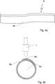
1 zeigt eine schematische Darstellung einer Ausführungsform der erfindungsgemäßen Ultraschallbearbeitungsvorrichtung.2a schematische Darstellung eines Ausgangsmaterials für eine Ausführungsform des erfindungsgemäßen Verfahrens.2b schematische Darstellung der in1 gezeigten Ausführungsform der Ultraschallbearbeitungsvorrichtung zur Bearbeitung des Materials nach2a .
1 shows a schematic representation of an embodiment of the ultrasonic processing device according to the invention.2a schematic representation of a starting material for an embodiment of the process according to the invention.2b schematic representation of the1 shown embodiment of the ultrasonic processing device for processing the material according to2a .
Die in
Um ein ungewolltes Abrollen der aufgerollten Materialbahn zu verhindern, wird mit der Ultraschallbearbeitungsvorrichtung 1 die äußere Schicht 6a mit der angrenzenden mittleren Schicht 6b verbunden. Dazu weist die Ultraschallbearbeitungsvorrichtung einen Generator 2 zur Erzeugung einer Ultraschallfrequenz auf, die an einen Konverter 3 weitergeleitet wird. Der Konverter 3 wandelt die Ultraschallfrequenz in eine mechanische Ultraschallschwingung um und regt damit die Sonotrode 4 an, deren Siegelfläche 5 in Kontakt mit der äußeren Schicht 6a steht, nachdem die Sonotrode 4 mit einer Zustellkraft auf das kompressible Material 6 gedrückt wurde, sodass dieses zusammengedrückt wird.In order to prevent the rolled-up material web from unrolling accidentally, the
Die Sonotrode 4 bewegt sich aufgrund der Ultraschallschwingung mit Schwingungsamplituden von 25 µm in der in
Die Zustellkraft und die Schwingungsamplitude der Sonotrode 4 sind dabei so gewählt, dass eine Gegenkraft, die von dem kompressiblen Material 6 der Sonotrode 4 entgegenwirkt, ausreicht, um eine Verbindung zwischen der äußeren Schicht 6a und der angrenzenden mittleren Schicht 6b zu bewirken. Ein zusätzliches Gegenwerkzeug ist nicht erforderlich. Die aufgerollte Materialbahn aus dem kompressiblen Material 6 fungiert als zweiter Energierichtungsgeber, der die Ultraschallenergie auf einen Fügebereich zwischen der äußeren Schicht 6a und der mittleren Schicht 6b fokussiert.The feed force and the vibration amplitude of the
Um die Schwingungsenergie gezielt in das kompressible Material 6 einzubringen, weist die Siegelfläche 5 der Sonotrode 4 einen Schlitz 7 auf. Der Schlitz 7 dient der gezielten Leitung der Schmelze, um die Verbindungsstabilität zwischen der äußeren Schicht 6a und der angrenzenden mittleren Schicht 6b zu verbessern.In order to introduce the vibration energy into the
Mit dem erfindungsgemäßen Ultraschallbearbeitungsverfahren bzw. der dazugehörigen Vorrichtung ist es möglich, eine aufgerollte Materialbahn eines kompressiblen Materials 6 zu verschließen, ohne weitere Klebemittel oder Siegelwerkzeuge zu verwenden.With the ultrasonic processing method according to the invention or the associated device, it is possible to seal a rolled-up material web of a
In den
Als Ausgangsmaterial 6 kommt, wie in
Zur Herstellung eines Tampons wird dieses Verbundmaterial aufgerollt, sodass mehrere aufeinander angeordnete Schichten 6a, 6b, 6c entstehen, wobei die innenliegende Schicht 6c aus der watteartigen Schicht gebildet wird, die von der folienartigen Schicht umgeben ist. Aufgrund der größeren Länge der folienartigen Schicht kommt es durch das Aufrollen zu einer Überlappung der folienartigen Schicht, sodass durch die folienartige Schicht eine äußere Schicht 6b und eine mittlere Schicht 6b gebildet werden, die mit der erfindungsgemäßen Ultraschallbearbeitungsvorrichtung 1 miteinander verbunden werden. Dadurch wird ein Lösen des aufgerollten Ausgangsmaterials verhindert.To produce a tampon, this composite material is rolled up to form
Bezugszeichenlistelist of reference symbols
- 11
- Ultraschallbearbeitungsvorrichtungultrasonic processing device
- 22
- Generatorgenerator
- 33
- Konverterconverter
- 44
- Sonotrodesonotrode
- 55
- Siegelflächesealing surface
- 66
- kompressibles Materialcompressible material
- 6a6a
- äußere Schichtouter layer
- 6b6b
- mittlere Schichtmiddle layer
- 6c6c
- innere Schichtinner layer
- 77
- Schlitzslot
Claims (14)
Translated fromGermanPriority Applications (1)
| Application Number | Priority Date | Filing Date | Title |
|---|---|---|---|
| DE102023114852.4ADE102023114852A1 (en) | 2023-06-06 | 2023-06-06 | Ultrasonic machining process for joining layers and ultrasonic machining device |
Applications Claiming Priority (1)
| Application Number | Priority Date | Filing Date | Title |
|---|---|---|---|
| DE102023114852.4ADE102023114852A1 (en) | 2023-06-06 | 2023-06-06 | Ultrasonic machining process for joining layers and ultrasonic machining device |
Publications (1)
| Publication Number | Publication Date |
|---|---|
| DE102023114852A1true DE102023114852A1 (en) | 2024-12-12 |
Family
ID=93566973
Family Applications (1)
| Application Number | Title | Priority Date | Filing Date |
|---|---|---|---|
| DE102023114852.4APendingDE102023114852A1 (en) | 2023-06-06 | 2023-06-06 | Ultrasonic machining process for joining layers and ultrasonic machining device |
Country Status (1)
| Country | Link |
|---|---|
| DE (1) | DE102023114852A1 (en) |
Citations (2)
| Publication number | Priority date | Publication date | Assignee | Title |
|---|---|---|---|---|
| US20220087874A1 (en)* | 2016-12-20 | 2022-03-24 | The Procter & Gamble Company | Apparatuses and methods for making absorbent articles with elastomeric laminates |
| EP4115861A1 (en)* | 2021-07-09 | 2023-01-11 | The Procter & Gamble Company | Methods and apparatuses for assembling elastic laminates with a rotating roll and removable layer |
- 2023
- 2023-06-06DEDE102023114852.4Apatent/DE102023114852A1/enactivePending
Patent Citations (2)
| Publication number | Priority date | Publication date | Assignee | Title |
|---|---|---|---|---|
| US20220087874A1 (en)* | 2016-12-20 | 2022-03-24 | The Procter & Gamble Company | Apparatuses and methods for making absorbent articles with elastomeric laminates |
| EP4115861A1 (en)* | 2021-07-09 | 2023-01-11 | The Procter & Gamble Company | Methods and apparatuses for assembling elastic laminates with a rotating roll and removable layer |
Similar Documents
| Publication | Publication Date | Title |
|---|---|---|
| DE69620637T2 (en) | ULTRASONIC SYSTEM AND METHOD | |
| DE69533878T2 (en) | PROCESS FOR PERFORATING THIN STRIP MATERIALS | |
| DE69425051T3 (en) | METHOD FOR PRODUCING AN ISOLATING MINERAL FIBER RAILWAY | |
| EP2547418B1 (en) | Method for producing a filter element folded in a zigzag shape | |
| EP3415213B1 (en) | Filter element | |
| EP3079895B1 (en) | Method for producing packaging, and packaging machine | |
| EP3102387B1 (en) | Ultrasonic welding device with preheating unit | |
| EP1492672B1 (en) | Device and method for the production of composite materials | |
| EP3727831B1 (en) | Tubular bag machine for producing paper bags | |
| DE102008028864B4 (en) | Adhesive bonding of folded honeycomb cores in sandwich structures, device and use | |
| EP3402662B1 (en) | Method and device for folding corrugated cardboard | |
| DE102023114852A1 (en) | Ultrasonic machining process for joining layers and ultrasonic machining device | |
| EP1535723A2 (en) | Apparatus for welding multilayered sheets | |
| WO2015185278A1 (en) | Method for producing a paper machine cloth | |
| DE102019202850A1 (en) | Method and device for joining paper material | |
| EP2225089B1 (en) | Method for the bonding of foils | |
| EP2014457B1 (en) | Tube forming equipment to form a tube of at least one material web | |
| DE29814704U1 (en) | Device for connecting a band-shaped nonwoven fabric with a strip of thermoplastic material | |
| DE10126866B4 (en) | Method and device for processing a material web with ultrasound | |
| EP2402272A2 (en) | Method and device for connecting two fibrous strips | |
| DE102023119882A1 (en) | Method for producing a sealing seam in packaging materials with layer jumps | |
| DE102020133602A1 (en) | Process for joining two joining surfaces | |
| DE19837124C1 (en) | Tampons for female hygiene | |
| EP3191643B1 (en) | Clothing and method of producing the clothing | |
| EP1499272A1 (en) | Disk, method for producing the same, and device for carrying out said method |
Legal Events
| Date | Code | Title | Description |
|---|---|---|---|
| R163 | Identified publications notified |