DE102023105701A1 - Robot arm device and robot arm with such a robot arm device - Google Patents
Robot arm device and robot arm with such a robot arm deviceDownload PDFInfo
- Publication number
- DE102023105701A1 DE102023105701A1DE102023105701.4ADE102023105701ADE102023105701A1DE 102023105701 A1DE102023105701 A1DE 102023105701A1DE 102023105701 ADE102023105701 ADE 102023105701ADE 102023105701 A1DE102023105701 A1DE 102023105701A1
- Authority
- DE
- Germany
- Prior art keywords
- robot arm
- robot
- tool
- arm device
- designed
- Prior art date
- Legal status (The legal status is an assumption and is not a legal conclusion. Google has not performed a legal analysis and makes no representation as to the accuracy of the status listed.)
- Ceased
Links
- 230000000295complement effectEffects0.000claimsdescription5
- 238000000034methodMethods0.000claimsdescription5
- 238000013461designMethods0.000description7
- 238000005259measurementMethods0.000description7
- 241000309551Arthraxon hispidusSpecies0.000description6
- 230000001276controlling effectEffects0.000description5
- 230000001105regulatory effectEffects0.000description4
- 238000011161developmentMethods0.000description2
- 238000006073displacement reactionMethods0.000description2
- 238000011477surgical interventionMethods0.000description2
- 238000001356surgical procedureMethods0.000description2
- 238000012549trainingMethods0.000description2
- BUHVIAUBTBOHAG-FOYDDCNASA-N(2r,3r,4s,5r)-2-[6-[[2-(3,5-dimethoxyphenyl)-2-(2-methylphenyl)ethyl]amino]purin-9-yl]-5-(hydroxymethyl)oxolane-3,4-diolChemical compoundCOC1=CC(OC)=CC(C(CNC=2C=3N=CN(C=3N=CN=2)[C@H]2[C@@H]([C@H](O)[C@@H](CO)O2)O)C=2C(=CC=CC=2)C)=C1BUHVIAUBTBOHAG-FOYDDCNASA-N0.000description1
- 230000015572biosynthetic processEffects0.000description1
- 230000000903blocking effectEffects0.000description1
- 238000011156evaluationMethods0.000description1
- 239000004744fabricSubstances0.000description1
- 230000000977initiatory effectEffects0.000description1
- 239000007788liquidSubstances0.000description1
- 238000012423maintenanceMethods0.000description1
- 239000002184metalSubstances0.000description1
- 238000012544monitoring processMethods0.000description1
- 238000012545processingMethods0.000description1
- 238000000926separation methodMethods0.000description1
- 238000012546transferMethods0.000description1
Images


Classifications
- B—PERFORMING OPERATIONS; TRANSPORTING
- B25—HAND TOOLS; PORTABLE POWER-DRIVEN TOOLS; MANIPULATORS
- B25J—MANIPULATORS; CHAMBERS PROVIDED WITH MANIPULATION DEVICES
- B25J13/00—Controls for manipulators
- B25J13/08—Controls for manipulators by means of sensing devices, e.g. viewing or touching devices
- B25J13/085—Force or torque sensors
Landscapes
- Engineering & Computer Science (AREA)
- Human Computer Interaction (AREA)
- Robotics (AREA)
- Mechanical Engineering (AREA)
- Manipulator (AREA)
Abstract
Translated fromGerman
Description
Translated fromGermanDie Erfindung betrifft eine Roboterarmeinrichtung sowie einen Roboterarm mit einer solchen Roboterarmeinrichtung.The invention relates to a robot arm device and a robot arm with such a robot arm device.
Aus der
Es ist bekannt, dass das Werkzeug an einem Werkzeugträger eines Linearschlittens angeordnet ist, wobei der Linearschlitten manuell längsverlagert werden kann, um eine gewünschte Position des Werkzeugs einzustellen.It is known that the tool is arranged on a tool carrier of a linear slide, wherein the linear slide can be manually longitudinally displaced in order to set a desired position of the tool.
Es ist ferner bekannt, einen 3D-Sensor einzusetzen, um der übergeordneten Steuerung des Roboters eine Bewegungsrichtung zur Positionierung des Linearaktuators im Raum vorzugeben. Ein solcher 3D-Sensor ist üblicherweise an einem Roboterarmsegment des Roboterarms montiert. Dabei kann es zu einer Diskrepanz zwischen der eingebrachten Soll-Bewegungsrichtung und der durch den Arm ausgeführten Ist-Bewegung kommen.It is also known to use a 3D sensor to specify a direction of movement for positioning the linear actuator in space to the higher-level controller of the robot. Such a 3D sensor is usually mounted on a robot arm segment of the robot arm. This can lead to a discrepancy between the desired direction of movement and the actual movement carried out by the arm.
Die Aufgabe der vorliegenden Erfindung besteht darin, eine Roboterarmeinrichtung sowie einen Roboterarm bereitzustellen, die bzw. der eine fehlerunanfällige Positionierung der Roboterarmeinrichtung im dreidimensionalen Raum ermöglicht.The object of the present invention is to provide a robot arm device and a robot arm which enables error-prone positioning of the robot arm device in three-dimensional space.
Diese Aufgabe wird durch eine Roboterarmeinrichtung mit den Merkmalen des Anspruchs 1 gelöst. Die Aufgabe wird ferner durch einen Roboterarm mit den Merkmalen des Anspruchs 9 gelöst. Die Aufgabe wird außerdem durch ein Verfahren zum Betreiben der Roboterarmeinrichtung mit den Merkmalen des Anspruchs 10 gelöst. Bevorzugte oder vorteilhafte Ausführungsformen der Erfindung ergeben sich aus den Unteransprüchen, der nachfolgenden Beschreibung sowie den beigefügten Figuren.This task is solved by a robot arm device with the features of
Gemäß einem ersten Erfindungsaspekt wird eine Roboterarmeinrichtung für einen Roboter vorgeschlagen, umfassend ein Strukturelement, das dazu ausgebildet ist, während des Betriebs des Roboters Arbeitskräfte aufzunehmen, wobei an diesem Strukturelement eine Bedieneinrichtung, umfassend ein Betätigungselement und eine damit wirkverbundene Sensoreinheit, angeordnet ist, wobei die Sensoreinheit dazu ausgebildet ist, eine in das Betätigungselement eingebrachte Sollwertvorgabe für eine Soll-Bewegungsrichtung der Roboterarmeinrichtung zu erfassen und die Sollwertvorgabe betreffende Daten an eine Steuereinheit zu übermitteln, wobei die Steuereinheit anhand der übermittelten Daten Befehlssignale zur Steuerung wenigstens eines Antriebs des Roboterarms erzeugt, um eine Lageveränderung der Roboterarmeinrichtung im dreidimensionalen Raum auszuführen.According to a first aspect of the invention, a robot arm device for a robot is proposed, comprising a structural element which is designed to accommodate workers during operation of the robot, an operating device comprising an actuating element and a sensor unit operatively connected thereto being arranged on this structural element, wherein the Sensor unit is designed to detect a setpoint specification introduced into the actuating element for a target direction of movement of the robot arm device and to transmit data relating to the setpoint specification to a control unit, the control unit using the transmitted data to generate command signals for controlling at least one drive of the robot arm in order to Change the position of the robot arm device in three-dimensional space.
Dadurch wird eine Entkopplung bzw. Auftrennung von Arbeitskräften, die während des Betriebs des Roboters von extern in die Roboterarmeinrichtung eingebracht wird, und Sollkräften, die durch manuelle Betätigung des Betätigungselements durch einen Nutzer in die Roboterarmeinrichtung eingebracht wird, ermöglicht, so dass auf Basis der Sollwertvorgabe durch den Nutzer eine der Soll-Bewegungsrichtung entsprechende Ist-Bewegungsrichtung der Roboterarmeinrichtung realisiert wird.This enables a decoupling or separation of workers, which are introduced externally into the robot arm device during operation of the robot, and target forces, which are introduced into the robot arm device through manual actuation of the actuating element by a user, so that on the basis of the target value specification an actual movement direction of the robot arm device corresponding to the target movement direction is realized by the user.
Arbeitskräfte im Sinn der Erfindung sind Kräfte, die beispielsweise im OP-Bereich während eines chirurgischen Eingriffs aufgrund einer Patientenverlagerung oder dergleichen auftreten können. Diese Kräfte werden zumindest mittelbar vom Strukturelement aufgenommen und in den Roboter, insbesondere in die Struktur des Roboterarms, abgeleitet.Workers in the sense of the invention are forces that can arise, for example, in the operating room during a surgical procedure due to a patient being moved or the like. These forces are at least indirectly absorbed by the structural element and transferred into the robot, in particular into the structure of the robot arm.
Eine Sollwertvorgabe wird erzeugt, indem der Nutzer das Betätigungselement manuell betätigt, wobei die Sensoreinheit die Betätigung als Eingabebefehl erfasst und entsprechende Daten erzeugt. Diese erfassten Daten, insbesondere die Messdaten, werden von der Sensoreinheit an die übergeordnete Steuereinheit des Roboterarms und/oder des Roboters übermittelt oder von der entsprechenden Steuereinheit abgerufen und weiterverarbeitet, so dass wenigstens ein Antrieb des Roboterarms angesteuert wird. Die Ansteuerung des wenigstens einen Antriebs des Roboterarms erfolgt derart, dass eine Bewegung der Roboterarmeinrichtung der Bewegungsvorgabe bzw. Sollwertvorgabe des Nutzers am Betätigungselement folgt. Anders gesagt wird durch den Nutzer eine gewünschte Bewegung, also eine Soll-Bewegung, zur Lageveränderung der Roboterarmeinrichtung über das Betätigungselement der Bedieneinheit vorgegeben, wobei die Steuereinheit diesen Eingabebefehl in entsprechende Befehlssignale umwandelt. Anhand dieser Befehlssignale erfolgt einer Steuerung und Regelung des wenigstens einen Antriebs des Roboterarms, derart, dass sich die Roboterarmeinrichtung in eine vom Nutzer gewünschte Position bewegt. Bei einem Roboterarm mit mehreren in Reihe geschalteten und über Gelenke verbundenen Roboterarmsegmenten sind eine Vielzahl von Antrieben vorgesehen, die in Folge der Eingabe des Nutzers zueinander verlagert und positioniert werden, bis die Roboterarmeinrichtung in der gewünschten Position ankommt. Die Lageveränderung der Roboterarmeinrichtung wird beendet, wenn der Nutzer das Betätigungselement nicht mehr betätigt bzw. wenn von der Sensoreinheit keine Betätigung des Betätigungselements erfasst wird.A setpoint specification is generated by the user manually actuating the actuating element, with the sensor unit detecting the actuation as an input command and generating corresponding data. This recorded data, in particular the measurement data, is transmitted by the sensor unit to the higher-level control unit of the robot arm and/or the robot or is retrieved and further processed by the corresponding control unit, so that at least one drive of the robot arm is controlled. The at least one drive of the robot arm is controlled in such a way that a movement of the robot arm device follows the movement specification or setpoint specification of the user on the actuating element. In other words, the user specifies a desired movement, i.e. a target movement, for changing the position of the robot arm device via the actuating element of the operating unit, with the control unit converting this input command into corresponding command signals. Based on these command signals, the at least one drive of the robot arm is controlled and regulated in such a way that the robot arm device moves into a position desired by the user. In a robot arm with several robot arm segments connected in series and connected via joints, a large number of drives are provided, which are shifted and positioned relative to one another as a result of the user's input until the robot arm device arrives in the desired position. The change in position of the robot arm device is ended when the user no longer operates the actuating element or when no actuation of the actuating element is detected by the sensor unit.
Die Steuereinheit ist eine Auswerte- und Steuereinheit, die Daten der Sensoreinheit empfangen und/oder anfordern sowie Befehlssignale erzeugen und an wenigstens einen Antrieb senden kann. Der Antrieb ist durch die Steuereinheit steuerbar und regelbar.The control unit is an evaluation and control unit that can receive and/or request data from the sensor unit and generate and send command signals to at least one drive. The drive can be controlled and regulated by the control unit.
Vorzugsweise ist die Roboterarmeinrichtung eine Werkzeugführungseinheit. Insbesondere ist die Werkzeugführungseinheit ein Linearaktuator und/oder ein rotativer Aktuator ist. Als Werkzeugführungseinheit ist eine Einheit zu verstehen, die dazu ausgebildet ist, wenigstens ein Werkzeug aufzunehmen und zu führen. Die Werkzeugführungseinheit ist bevorzugt an einem von einer Basis bzw. einem Anbindungspunkt des Roboterarms entgegengesetzten Ende des Roboterarms angeordnet.Preferably, the robot arm device is a tool guide unit. In particular, the tool guide unit is a linear actuator and/or a rotary actuator. A tool guide unit is to be understood as a unit that is designed to hold and guide at least one tool. The tool guide unit is preferably arranged at an end of the robot arm opposite a base or a connection point of the robot arm.
Der Linearaktuator ist zur Werkzeugführung eines Werkzeugs eingerichtet. Als Linearaktuator ist eine Vorrichtung zu verstehen, die eine Drehbewegung einer Antriebseinheit, insbesondere eines Motors, in eine lineare Bewegung umwandelt. Dies ermöglicht es, das daran angeordnete Werkzeug auf einer geraden Linie zu bewegen. Als Motor des Linearaktuator eignet sich insbesondere eine elektrische Maschine. Als rotativer Aktuator ist ein Aktuator zu verstehen, der am Werkzeug eine Drehzahl und ein Drehmoment erzeugt. Auch eine Kombination aus einem Linearaktuator und einem rotativen Aktuator ist denkbar.The linear actuator is set up to guide a tool. A linear actuator is a device that converts a rotary movement of a drive unit, in particular a motor, into a linear movement. This allows the tool attached to it to move in a straight line. An electric machine is particularly suitable as the motor for the linear actuator. A rotary actuator is an actuator that generates a speed and a torque on the tool. A combination of a linear actuator and a rotary actuator is also conceivable.
An dem Strukturelement einer vorzugsweise als Linearaktuator ausgebildeten Roboterarmeinrichtung sind eine Werkzeugaufnahme sowie ein Linearschlitten mit einem Werkzeugträger angeordnet, wobei der Linearschlitten relativ zum Strukturelement und zur Werkzeugaufnahme längsverlagerbar angeordnet ist, wobei der Werkzeugträger dazu ausgebildet ist, ein Werkzeug aufzunehmen, und wobei die Werkzeugaufnahme dazu ausgebildet ist, das Werkzeug bei Längsverlagerung des Linearschlittens axial zu führen, wobei die Bedieneinrichtung im Bereich der Werkzeugaufnahme am Strukturelement angeordnet ist.A tool holder and a linear slide with a tool holder are arranged on the structural element of a robot arm device, preferably designed as a linear actuator, the linear slide being arranged to be longitudinally displaceable relative to the structural element and the tool holder, the tool holder being designed to hold a tool, and the tool holder being designed to do so is to guide the tool axially when the linear slide is displaced longitudinally, the operating device being arranged in the area of the tool holder on the structural element.
Als Strukturelement kann prinzipiell jedes Bauteil des Roboterarms verstanden werden, das für den Nutzer zugänglich, insbesondere manuell betätigbar, ist. Vorzugsweise ist das Strukturelement ein Gehäuse, ein Gehäuseabschnitt oder ein Rahmenteil des Roboterarms. Bevorzugt ist das Strukturelement ein Gehäuse, ein Gehäuseabschnitt oder ein Rahmenteil eines Roboterarmsegments.In principle, a structural element can be understood as any component of the robot arm that is accessible to the user, in particular can be operated manually. Preferably, the structural element is a housing, a housing section or a frame part of the robot arm. The structural element is preferably a housing, a housing section or a frame part of a robot arm segment.
Der genannte Linearaktuator ist dazu ausgebildet, zum Beispiel über das Strukturelement an einem Roboterarm eines Roboters, insbesondere einem Roboterarmsegment des Roboterarms, verschwenkbar angeordnet zu sein. Am Linearaktuator ist je nach Anwendungsfall des Roboters ein Werkzeug längsverlagerbar angeordnet. Das Werkzeug kann beispielsweise im Fall eines Operations-Roboters, nachfolgend auch OP-Roboter genannt, ein Instrument sein, das für einen chirurgischen Eingriff zum Einsatz kommen kann. Das Werkzeug kann insbesondere ein Greifarm, ein Rohr zur Aufnahme eines oder mehrerer weiterer Elemente oder Werkzeuge, ein Bohrer oder dergleichen sein. Im OP-Bereich kann das Instrument insbesondere ein Trokar bzw. ein Trokarhalter sein. Jedenfalls ist das Werkzeug ein längliches Bauteil, dass zum einen am Werkzeugträger angeordnet bzw. aufgenommen ist und zum anderen durch die Werkzeugaufnahme axial geführt ist.The linear actuator mentioned is designed to be pivotably arranged, for example via the structural element on a robot arm of a robot, in particular a robot arm segment of the robot arm. Depending on the application of the robot, a tool is arranged on the linear actuator so that it can be moved longitudinally. For example, in the case of a surgical robot, hereinafter also referred to as a surgical robot, the tool can be an instrument that can be used for a surgical procedure. The tool can in particular be a gripper arm, a tube for holding one or more further elements or tools, a drill or the like. In the operating room, the instrument can in particular be a trocar or a trocar holder. In any case, the tool is an elongated component that, on the one hand, is arranged or received on the tool carrier and, on the other hand, is guided axially by the tool holder.
Der Linearschlitten ist eine Plattform, auf der der Werkzeugträger, insbesondere lösbar, angeordnet ist. Der Werkzeugträger kann also lösbar, also auswechselbar, am Linearschlitten angeordnet sein. Der Linearschlitten ist entlang einer Führungsvorrichtung, insbesondere einer Führungsschiene, oder dergleichen am Strukturelement geführt. Die Einstellung einer Längsposition des Linearschlittens relativ zum Strukturelement kann manuell, teilautomatisch und/oder vollautomatisch erfolgen.The linear slide is a platform on which the tool carrier is arranged, in particular in a detachable manner. The tool carrier can therefore be arranged on the linear slide in a detachable, i.e. replaceable, manner. The linear slide is guided along a guide device, in particular a guide rail, or the like on the structural element. The adjustment of a longitudinal position of the linear slide relative to the structural element can be done manually, semi-automatically and/or fully automatically.
Der Werkzeugträger weist Mittel zur Aufnahme des Werkzeugs auf. Wenn das Werkzeug ein Bohrer oder dergleichen ist, kann der Werkzeugträger ein Bohraufnahmefutter oder dergleichen aufweisen. Der Werkzeugträger umfasst vorzugsweise eine Antriebseinheit, die dazu vorgesehen ist, das Werkzeug zu betätigen. Die Antriebseinheit kann ein Aktuator sein oder umfassen, der beispielsweise als elektrische Maschine ist, wobei bei Betätigung der Antriebseinheit das Werkzeug beispielsweise in eine rotative Bewegung versetzbar ist. Alternativ kann, wenn das Werkzeug ein Greifer oder dergleichen ist, eine Greifbewegung ausgeführt werden. Mit anderen Worten wird das Werkzeug am Werkzeugträger nicht nur aufgenommen, sondern auch angetrieben. Mittels des Linearschlittens und des daran angeordneten Werkzeugträgers ist das Werkzeug also linear verfahrbar sowie, falls erforderlich, betätigbar, also antreibbar. Über den Werkzeugträger kann ferner eine Elektronik, insbesondere elektrische Leitungen, zum Werkzeug geführt sein.The tool carrier has means for holding the tool. If the tool is a drill or the like, the tool carrier can have a drill chuck or the like. The tool carrier preferably comprises a drive unit which is intended to operate the tool. The drive unit can be or include an actuator, which is, for example, an electrical machine, wherein when the drive unit is actuated, the tool can be set into a rotary movement, for example. Alternatively, if the tool is a gripper or the like, a gripping movement can be performed. In other words, the tool is not only held on the tool carrier, but also driven. By means of the linear slide and the tool carrier arranged thereon, the tool can be moved linearly and, if necessary, actuated, i.e. driven. Electronics, in particular electrical lines, can also be routed to the tool via the tool carrier.
Die Werkzeugaufnahme ist dazu ausgebildet, das Werkzeug während der Längsverlagerung des Linearschlittens in dessen axialer Richtung zu führen sowie in dessen radialer Richtung abzustützen. Über die Werkzeugaufnahme werden auf das Werkzeug einwirkende Querkräfte aufgenommen. Derartige seitliche Kräfte können beispielsweise im OP-Bereich aufgrund einer Patientenverlagerung auftreten. Die Kräfte werden von der Werkzeugaufnahme aufgenommen und auf das Strukturelement, mit dem die Werkzeugaufnahme fest verbunden ist, übertragen und in die Struktur des Roboterarms abgeleitet.The tool holder is designed to guide the tool in the axial direction during the longitudinal displacement of the linear slide and to support it in the radial direction. Transverse forces acting on the tool are absorbed via the tool holder. Such lateral forces can occur, for example, in the operating room area due to a patient shifting. The forces are absorbed by the tool holder and transferred to the structural element to which the tool holder is firmly connected and transferred into the structure of the robot arm.
Die Bedieneinrichtung ist im Linearaktuator, und somit an keinem anderen Roboterarmsegment des Roboterarms, integriert, wodurch eine bessere Handhabbarkeit zur Positionierung des Linearaktuators während der Nutzung des Roboters realisiert wird. Dadurch, dass die Bedieneinrichtung mit dem Betätigungselement und der Sensoreinheit im Bereich der Werkzeugaufnahme am Strukturelement angeordnet ist, erfolgt neben der Kraftabstützung während des Betriebs des Roboters zudem eine manuelle Manipulation des Roboterarms an einem gemeinsamen Punkt des Linearaktuators. Durch die Manipulation des Roboterarms, insbesondere des Linearaktuators, kann der Linearaktuator sowie das Werkzeug zum zu bearbeiteten Gegenstand oder dem zu behandelnden Patienten im Raum ausgerichtet und positioniert werden. Im OP-Bereich kann durch einen Bediener oder Nutzer des Roboters bzw. einen Operateur ein sogenanntes „Teach-In“ bzw. ein Anlernen des Linearaktuators erfolgen, wobei das am Linearaktuator angeordnete Werkzeug für den Eingriff an den Patienten heranführbar und positionierbar ist.The operating device is integrated in the linear actuator and therefore not on any other robot arm segment of the robot arm, which means that better handling is achieved for positioning the linear actuator while using the robot. Because the operating device with the actuating element and the sensor unit is arranged in the area of the tool holder on the structural element, in addition to the force support during operation of the robot, there is also manual manipulation of the robot arm at a common point on the linear actuator. By manipulating the robot arm, in particular the linear actuator, the linear actuator and the tool can be aligned and positioned in space in relation to the object to be processed or the patient to be treated. In the operating room area, a so-called “teach-in” or training of the linear actuator can be carried out by an operator or user of the robot or a surgeon, whereby the tool arranged on the linear actuator can be brought up to the patient and positioned for the procedure.
Die Positionierung des Linearaktuators im Raum erfolgt demnach, in dem der Nutzer über die Bedieneinrichtung eine Bewegungsrichtung des Linearaktuators vorgibt. Dabei werden die über das Betätigungselement auf den Linearaktuator eingebrachten manuellen Betätigungskräfte von der Sensoreinheit erfasst. Die Sensoreinheit ist mit der Steuereinheit kommunizierend verbunden, wobei von der Sensoreinheit erfasste Messdaten, die infolge der manuellen Betätigung des Betätigungselements erzeugt werden, an die Steuereinheit übertragen werden. Die Messdaten werden von der Steuereinheit verarbeitet und zu Befehlssignalen zur Steuerung und Regelung wenigstens eines Antriebs des Roboters und/oder des Roboterarms umgewandelt werden. Die Sensoreinheit ist vorzugsweise eine Kraft-Sensoreinheit.The linear actuator is positioned in space by the user specifying a direction of movement of the linear actuator via the operating device. The manual actuation forces applied to the linear actuator via the actuating element are detected by the sensor unit. The sensor unit is communicatively connected to the control unit, with measurement data recorded by the sensor unit, which is generated as a result of the manual actuation of the actuating element, being transmitted to the control unit. The measurement data is processed by the control unit and converted into command signals for controlling and regulating at least one drive of the robot and/or the robot arm. The sensor unit is preferably a force sensor unit.
Bevorzugt ist das Betätigungselement eine Spacemouse oder ein sogenannter 3-Achsen-Joystick bzw. 3D-Joystick. Eine „Spacemouse“ ist ein an sich bekanntes Eingabegerät, das dazu ausgebildet ist, den Roboterarm zur Positionierung des Linearaktuators im Raum zu manipulieren. Es handelt sich um ein ergonomisches Gerät, das der Nutzer in der Hand halten kann. Die Spacemouse ist eine Art Joystick, der mehrere Tasten und/oder eine Navigationskugel aufweisen kann. Der 3D-Joystick ist ein ebenfalls an sich bekanntes Eingabegerät, das beispielsweise eine Gelenkaufnahme, beispielsweise in Form einer Gelenkpfanne, umfasst, die einen Gelenkkopf gelenkig aufnimmt und translatorische Bewegungen desselben verhindert. Die Bewegung des Gelenkkopfes relativ zur Gelenkaufnahme ist erfassbar, wobei anhand der erfassten Messdaten Befehlssignale zur Steuerung und Regelung des zumindest einen Antriebs des Roboterarms erzeugbar sind.The actuating element is preferably a space mouse or a so-called 3-axis joystick or 3D joystick. A “space mouse” is a known input device that is designed to manipulate the robot arm to position the linear actuator in space. It is an ergonomic device that the user can hold in his hand. The Spacemouse is a type of joystick that can have several buttons and/or a navigation ball. The 3D joystick is also a known input device, which includes, for example, a joint holder, for example in the form of a joint socket, which holds a joint head in an articulated manner and prevents translational movements of the same. The movement of the joint head relative to the joint receptacle can be detected, with command signals for controlling and regulating the at least one drive of the robot arm being able to be generated based on the recorded measurement data.
Die Sensoreinheit kann derart ausgebildet sein, dass sie Bewegungen des Betätigungselements der Bedieneinrichtung in ein bis sechs Achsen bzw. Dimensionen auslesen kann. Je vielseitiger das Betätigungselement betätigt und je genauer die Sensoreinheit diese Bewegungen erfassen kann, desto genauer kann der Linearaktuator im Raum positioniert werden. Die Bedieneinrichtung ist so eingerichtet, dass der Nutzer den Linearaktuator mit nur einer Hand in seiner Position einstellen kann. Das Betätigungselement ist dabei vorzugsweise so ausgebildet, dass der Nutzer es mit seiner Hand wenigstens teilweise umgreifen kann. Das Betätigungselement kann eine für die Hand des Nutzers ergonomische äußere Form aufweisen.The sensor unit can be designed in such a way that it can read movements of the actuating element of the operating device in one to six axes or dimensions. The more versatile the actuating element is actuated and the more precisely the sensor unit can detect these movements, the more precisely the linear actuator can be positioned in space. The operating device is set up in such a way that the user can adjust the position of the linear actuator with just one hand. The actuating element is preferably designed in such a way that the user can at least partially grasp it with his hand. The actuating element can have an external shape that is ergonomic for the user's hand.
Das Betätigungselement kann zudem ein- oder mehrteilig ausgebildet sein. Wenn die Sensoreinheit innerhalb des Betätigungselements angeordnet ist, kann eine mehrteilige Ausgestaltung des Betätigungselements vorteilhaft sein, um eine Montage der Bedieneinrichtung, insbesondere der Sensoreinheit, zu vereinfachen.The actuating element can also be designed in one or more parts. If the sensor unit is arranged within the actuating element, a multi-part design of the actuating element can be advantageous in order to simplify assembly of the operating device, in particular the sensor unit.
Die Sensoreinheit kann ferner so ausgelegt sein, dass sie erfassen kann, wenn der Linearaktuator auf ein Hindernis stößt. Alternativ können am Antrieb des Roboters, insbesondere des Roboterarms, Mittel vorgesehen sein, die erfassen, wenn der Linearaktuator auf ein Hindernis stößt. Dies kann beispielsweise durch Messung oder Überwachung eines elektrischen Stroms in dem mindestens einen Antrieb des Roboterarms erfolgen. Insbesondere bei als sogenannter „Cobot“ ausgebildeten Robotern ist eine derartige Weiterbildung vorteilhaft.The sensor unit can also be designed so that it can detect when the linear actuator encounters an obstacle. Alternatively, means can be provided on the drive of the robot, in particular the robot arm, which detect when the linear actuator encounters an obstacle. This can be done, for example, by measuring or monitoring an electrical current in the at least one drive of the robot arm. Such further training is particularly advantageous for robots designed as so-called “cobots”.
Nach einem Ausführungsbeispiel umfasst die Werkzeugaufnahme einen brückenförmigen Träger, wobei der Träger eine erste Aussparung zur axialen Führung des Werkzeugs umfasst, und wobei die Bedieneinrichtung wenigstens teilweise räumlich innerhalb des Trägers angeordnet ist. Die erste Aussparung kann direkt am Träger oder an einer Ausformung des Trägers angeordnet sein. Das Werkzeug wird bei Befestigung am Werkzeugträger zusätzlich durch die erste Aussparung am Träger axial hindurchgeführt. Vorzugsweise ist das Werkzeug derart ausgebildet, dass seine Außenmantelfläche komplementär zur Innengeometrie der ersten Aussparung ausgebildet ist, um eine sichere axiale Führung sowie radiale Abstützung von Querkräften zu ermöglichen.According to one exemplary embodiment, the tool holder comprises a bridge-shaped carrier, wherein the carrier comprises a first recess for axially guiding the tool, and wherein the operating device is at least partially spatially arranged within the carrier. The first recess can be arranged directly on the carrier or on a formation of the carrier. When attached to the tool carrier, the tool is also guided axially through the first recess on the carrier. Preferably, the tool is designed such that its outer surface is complementary to the internal geometry of the first recess is designed to enable secure axial guidance and radial support of transverse forces.
Als brückenförmiger Träger ist ein Bauteil oder Abschnitt der Werkzeughalterung zu verstehen, das bzw. der einen räumlich innenliegenden Frei- bzw. Hohlraum aufweist, der wiederum so ausgeformt ist, dass die Bedieneinrichtung wenigstens teilweise darin aufgenommen ist aber nicht mit dem Träger in Kontakt kommt, sodass eine sichere Betätigung des Betätigungselements sichergestellt ist. Mithin sind das Betätigungselement und/oder die Sensoreinheit räumlich innerhalb der Werkzeugaufnahme angeordnet, wobei keine Berührung zwischen diesen Elementen der Bedieneinrichtung und dem Träger direkt erfolgt. Die Bedieneinrichtung ist also frei von Kontaktpunkten oder -flächen mit dem Träger des Werkzeughalters, sondern ist lediglich am Strukturelement angeordnet. Damit wird sichergestellt, dass das Betätigungselement zur Positionierung des Linearaktuators im dreidimensionalen Raum ungehindert betätigt werden kann.A bridge-shaped carrier is to be understood as a component or section of the tool holder which has a spatially internal free space or cavity, which in turn is shaped in such a way that the operating device is at least partially accommodated therein but does not come into contact with the carrier, so that safe operation of the actuating element is ensured. The actuating element and/or the sensor unit are therefore arranged spatially within the tool holder, with no direct contact between these elements of the operating device and the carrier. The operating device is therefore free of contact points or surfaces with the carrier of the tool holder, but is only arranged on the structural element. This ensures that the actuating element for positioning the linear actuator in three-dimensional space can be actuated unhindered.
In diesem Zusammenhang ist es vorteilhaft, wenn das Strukturelement und die Werkzeugaufnahme einteilig ausgebildet sind. Das Strukturelement und die Werkzeugaufnahme können aus einem Teil gefertigt sein. Durch die einteilige Ausgestaltung wird eine hohe Steifigkeit des Systems realisiert, wodurch insbesondere auf den Linearaktuator einwirkende Querkräfte optimale aufgenommen und in den Roboterarm abgeleitet werden können.In this context, it is advantageous if the structural element and the tool holder are designed in one piece. The structural element and the tool holder can be made from one part. The one-piece design ensures a high level of rigidity in the system, which means that transverse forces acting on the linear actuator in particular can be optimally absorbed and diverted into the robot arm.
Denkbar ist jedoch, dass das Strukturelement und die Werkzeugaufnahme vor der Montage zunächst zweiteilig ausgestaltet sind und während der Montage fest miteinander verbunden werden. Dies kann sowohl eine Schraubverbindung als auch eine Schweißverbindung sein.However, it is conceivable that the structural element and the tool holder are initially designed in two parts before assembly and are firmly connected to one another during assembly. This can be either a screw connection or a welded connection.
Nach einem weiteren Ausführungsbeispiel umfasst die Werkzeugaufnahme ein am Strukturelement befestigtes Basiselement sowie einen Aufnahmekörper, wobei der Aufnahmekörper eine erste Aussparung umfasst, die dazu ausgebildet ist, das Werkzeug in dessen axialer Richtung zu führen, und wobei das Basiselement am Strukturelement befestigt ist. Das Basiselement ist als Träger im Sinn der vorherigen Ausführungen zu verstehen und ist fest, insbesondere einteilig, mit dem Strukturelement verbunden.According to a further exemplary embodiment, the tool holder comprises a base element attached to the structural element and a receiving body, wherein the receiving body comprises a first recess which is designed to guide the tool in its axial direction, and wherein the base element is attached to the structural element. The base element is to be understood as a carrier in the sense of the previous statements and is firmly, in particular in one piece, connected to the structural element.
Das Werkzeug wird bei Befestigung am Werkzeugträger zusätzlich durch die erste Aussparung am Aufnahmekörper axial hindurchgeführt. Vorzugsweise ist das Werkzeug derart ausgebildet, dass seine Außenmantelfläche komplementär zur Innengeometrie der ersten Aussparung ausgebildet ist, um eine sichere axiale Führung und radiale Abstützung von Querkräften zu ermöglichen.When attached to the tool carrier, the tool is also guided axially through the first recess on the receiving body. The tool is preferably designed in such a way that its outer surface is designed to be complementary to the internal geometry of the first recess in order to enable secure axial guidance and radial support of transverse forces.
Bevorzugt ist das Basiselement zur Aufnahme eines Betätigungsstifts der Sensoreinheit wenigstens abschnittsweise hülsenförmig ausgebildet, wobei das Betätigungselement das Basiselement wenigstens teilweise umgibt und frei von Kontaktflächen mit dem Basiselement ist, wobei am Basiselement Durchbrüche ausgebildet sind, durch die ein Steg des Betätigungselements hindurchgeführt und am Betätigungsstift der Sensoreinheit befestigt ist. Mit anderen Worten ist das Basiselement wenigstens abschnittsweise rohrförmig ausgebildet und umgibt den Betätigungsstift der Sensoreinheit räumlich, ohne in Kontakt damit zu kommen. Die Bedieneinrichtung ist demnach als 3D-Joystick ausgebildet.The base element for receiving an actuating pin of the sensor unit is preferably designed to be sleeve-shaped at least in sections, the actuating element at least partially surrounding the base element and being free of contact surfaces with the base element, openings being formed on the base element through which a web of the actuating element passes and on the actuating pin Sensor unit is attached. In other words, the base element is at least partially tubular and spatially surrounds the actuating pin of the sensor unit without coming into contact with it. The operating device is therefore designed as a 3D joystick.
Der Betätigungsstift ist lediglich mit dem Betätigungselement der Bedieneinrichtung mechanisch verbunden, beispielsweise durch Schrauben oder dergleichen, sodass der Betätigungsstift der Sensoreinheit bei einer auf das Betätigungselement manuell eingebrachten Betätigungskraft zur Positionierung des Linearaktuators ebenfalls betätigt wird. Die Sensoreinheit ist dazu ausgebildet, Bewegungen des Betätigungsstifts zu Messdaten zu verarbeiten, um den wenigstens einen Antrieb des Roboterarms zur Positionierung des Linearaktuators im Raum anzusteuern.The actuating pin is only mechanically connected to the actuating element of the operating device, for example by screws or the like, so that the actuating pin of the sensor unit is also actuated when the actuating force is manually applied to the actuating element for positioning the linear actuator. The sensor unit is designed to process movements of the actuating pin into measurement data in order to control the at least one drive of the robot arm for positioning the linear actuator in space.
Die Sensoreinheit weist neben dem Betätigungsstift vorzugsweise einen einteilig damit verbundenen und im Wesentlichen kugelförmig ausgebildeten Gelenkkopf auf, der in einer Gelenkaufnahme, insbesondere einer Gelenkpfanne oder dergleichen aufgenommen und beweglich angeordnet ist. Durch diese Geometrie ist der Betätigungsstift mit dem Gelenkkopf zumindest dreiachsig drehbar, wobei translatorische Bewegungen relativ zum Strukturelement nicht möglich sind. Die Gelenkpfanne kann am Strukturelement ausgebildet sein oder mit dem Strukturelement, insbesondere lösbar, verbunden sein.In addition to the actuating pin, the sensor unit preferably has a joint head which is connected in one piece and is essentially spherical and which is received and movably arranged in a joint receptacle, in particular a joint socket or the like. Due to this geometry, the actuating pin with the joint head can be rotated at least in three axes, with translational movements relative to the structural element not being possible. The joint socket can be formed on the structural element or can be connected to the structural element, in particular releasably.
Vorteilhaft ist, wenn das Betätigungselement mehrteilig ausgebildet ist, wobei Segmente des Betätigungselements nach Montage der Sensoreinheit miteinander verbunden werden, beispielsweise durch Verschrauben oder durch miteinander formschlüssige verbindbare Elemente. Das Betätigungselement kann aus dünnwandigen Segmenten aus Kunststoff oder Blech ausgebildet sein und eine Topf- oder Tassenform aufweisen. Der Steg, der frei von Berührungspunkten oder -flächen durch die Durchbrüche des Basiselements hindurchgeführt ist, kann dabei zusammen mit dem Basiselement der Werkzeugaufnahme räumlich innerhalb des topf- bzw. tassenförmigen Betätigungselements angeordnet sein. Die Durchbrüche sind bevorzugt durch elastische Elemente abgedichtet, um den Innenraum des Linearaktuators, insbesondere der Bedieneinrichtung, vor dem unerwünschten Eintritt von Schmutz oder Flüssigkeit zu schützen.It is advantageous if the actuating element is designed in several parts, with segments of the actuating element being connected to one another after assembly of the sensor unit, for example by screwing or by positively connectable elements. The actuating element can be formed from thin-walled segments made of plastic or sheet metal and have a pot or cup shape. The web, which is guided through the openings of the base element without contact points or surfaces, can be spatially located together with the base element of the tool holder within the pot-shaped or cup-shaped actuating element be arranged. The openings are preferably sealed by elastic elements in order to protect the interior of the linear actuator, in particular the operating device, from the unwanted entry of dirt or liquid.
Der Aufnahmekörper kann je nach Anforderung ein- oder mehrteilig mit dem Basiselement verbunden sein. Eine einteilige Ausgestaltung ist von Vorteil, wenn eine besonders sichere axiale Führung des Werkzeugs am Werkzeughalter und gegebenenfalls eine kompaktere Ausgestaltung des Werkzeughalters gefordert ist. Mithin realisiert eine einteilige Ausführung eine vergleichsweise hohe Steifigkeit.Depending on the requirements, the holder body can be connected to the base element in one or more parts. A one-piece design is advantageous if a particularly secure axial guidance of the tool on the tool holder and possibly a more compact design of the tool holder is required. A one-piece design therefore achieves a comparatively high level of rigidity.
Andererseits kann eine mehrteilige Ausgestaltung vorteilhaft sein, um beispielsweise eine Position des Linearaktuators im Raum festsetzen bzw. sichern zu können. In diesem Sinn ist der Aufnahmekörper bevorzugt lösbar am Basiselement angeordnet, wobei der Aufnahmekörper eine komplementär zu einem axialen Abschnitt des Betätigungsstifts ausgeformte zweite Aussparung aufweist, wobei, wenn der Aufnahmekörper am Basiselement befestigt ist, der axiale Abschnitt des Betätigungsstifts in der zweiten Aussparung axial aufgenommen und radial abgestützt ist. Damit kann zwischen zwei Betriebsmodi gewechselt werden.On the other hand, a multi-part design can be advantageous, for example in order to be able to set or secure a position of the linear actuator in space. In this sense, the receiving body is preferably detachably arranged on the base element, the receiving body having a second recess which is shaped complementary to an axial section of the actuating pin, wherein, when the receiving body is attached to the base element, the axial section of the actuating pin is axially received in the second recess and is supported radially. This allows you to switch between two operating modes.
Wenn der Aufnahmekörper nicht mit dem Basiselement lösbar verbunden ist, ist auch der axiale Abschnitt des Betätigungsstifts nicht in der zweiten Aussparung aufgenommen, wodurch der Betätigungsstift der Sensoreinheit relativ zum Werkzeughalter beweglich ist. Somit kann das mit dem Betätigungsstift mechanisch verbundene Betätigungselement durch den Nutzer betätigt und folglich ein Eingabebefehl für die Positionierung des Linearaktuators durch die Sensoreinheit sensiert werden. Dies ist als manuell initiierte Einstellung der Position des Linearaktuators im Raum zu verstehen. Hierbei kann die Steuereinheit dazu ausgebildet sein, eine eingestellte Position des Linearaktuators elektronisch zu blockieren.If the receiving body is not detachably connected to the base element, the axial section of the actuating pin is also not received in the second recess, whereby the actuating pin of the sensor unit is movable relative to the tool holder. Thus, the actuating element mechanically connected to the actuating pin can be actuated by the user and consequently an input command for the positioning of the linear actuator can be sensed by the sensor unit. This is to be understood as a manually initiated adjustment of the position of the linear actuator in space. The control unit can be designed to electronically block a set position of the linear actuator.
Beispielsweise wenn eine gewünschte Position des Linearaktuators im Raum eingestellt wurde, kann der Aufnahmekörper mit dem Basiselement des Werkzeughalters lösbar verbunden werden, wobei der axiale Abschnitt des Betätigungsstifts gleichzeitig in die zweite Aussparung eingeschoben wird, so dass eine translatorische Bewegung des Betätigungsstifts relativ zum Aufnahmekörper verhindert wird. Da das Basiselement des Werkzeughalters fest mit dem Strukturelement verbunden ist, wird so eine Bewegung des Betätigungsstifts relativ zum Werkzeughalter bzw. dem Strukturelement verhindert bzw. blockiert. Infolgedessen kann das mit dem Betätigungsstift mechanisch verbundene Betätigungselement durch den Nutzer nicht bewegt und folglich kein Eingabebefehl durch die Sensoreinheit sensiert werden, um eine Positionseinstellung des Linearaktuators im Raum zu initiieren bzw. auszuführen. Damit kann eine ungewollte Betätigung des Linearaktuators verhindert werden, wodurch beispielsweise im OP-Bereich die Sicherheit des Operateurs und des Patienten erhöht wird. Alternativ oder ergänzend kann ein Automatikmodus realisiert werden, bei dem nur eine computergestützte Verstellung des Linearaktuators im Raum erfolgen kann. Dies ist als wenigstens teilautomatisch erfolgende Einstellung der Position des Linearaktuators im Raum zu verstehen.For example, if a desired position of the linear actuator has been set in space, the receiving body can be detachably connected to the base element of the tool holder, the axial section of the actuating pin being simultaneously inserted into the second recess, so that a translational movement of the actuating pin relative to the receiving body is prevented . Since the base element of the tool holder is firmly connected to the structural element, movement of the actuating pin relative to the tool holder or the structural element is prevented or blocked. As a result, the actuating element mechanically connected to the actuating pin cannot be moved by the user and consequently no input command can be sensed by the sensor unit in order to initiate or carry out a position adjustment of the linear actuator in space. This can prevent unwanted actuation of the linear actuator, which increases the safety of the surgeon and the patient, for example in the operating room. Alternatively or additionally, an automatic mode can be implemented in which only computer-aided adjustment of the linear actuator in space can take place. This is to be understood as an at least partially automatic adjustment of the position of the linear actuator in space.
Vorzugsweise weist das Strukturelement auf einer der Werkzeugaufnahme entgegengesetzten Seite eine Montageöffnung zur Montage der Bedieneinrichtung auf. Diese Seite des Strukturelements wird nachfolgend auch als Unterseite des Strukturelements bezeichnet, wenngleich sie je nach Position des Linearaktuators im Raum nicht zwingend dem Boden zugewandt sein muss. Durch die Montageöffnung wird die Bedieneinrichtung am Strukturelement fixiert und kann, beispielsweise für Instandhaltungsmaßnahmen, in einfacher Weise demontiert und gegebenenfalls ausgetauscht werden. Dies kann je nach Ausgestaltung des Linearaktuators auch dann umgesetzt werden, wenn das Werkzeug bereits am Werkzeugträger angebunden und durch den Werkzeughalter gehalten ist. Mithin ist die Bedieneinrichtung durch die Montageöffnung besser zugänglich. Bevorzugt ist die Montageöffnung von einem Deckel verschließbar ausgebildet. Das Strukturelement weist demnach Mittel zur Aufnahme eines Deckels auf, beispielsweise in Form von Scharnieren und/oder Formschlusselementen.The structural element preferably has a mounting opening for mounting the operating device on a side opposite the tool holder. This side of the structural element is also referred to below as the underside of the structural element, although depending on the position of the linear actuator in space it does not necessarily have to face the floor. The operating device is fixed to the structural element through the assembly opening and can be easily dismantled and, if necessary, replaced, for example for maintenance measures. Depending on the design of the linear actuator, this can also be implemented if the tool is already connected to the tool carrier and held by the tool holder. The operating device is therefore more accessible through the mounting opening. The mounting opening is preferably designed to be closable by a cover. The structural element therefore has means for receiving a lid, for example in the form of hinges and/or positive locking elements.
Bevorzugt ist an der Bedieneinrichtung wenigstens ein Schalter angeordnet. Der wenigstens eine Schalter ist dazu ausgebildet, zwischen Schaltzuständen zu schalten. Der wenigstens eine Schalter kann ein mechanischer Schalter am Betätigungselement sein, der kommunizierend mit der Steuereinheit des Roboters verbunden ist. Denkbar ist auch, dass am Betätigungselement ein Touchscreen angeordnet ist mit einem oder mehreren Tasten als Schalter im Sinn der Erfindung.At least one switch is preferably arranged on the operating device. The at least one switch is designed to switch between switching states. The at least one switch can be a mechanical switch on the actuating element, which is communicatively connected to the control unit of the robot. It is also conceivable that a touchscreen is arranged on the actuating element with one or more buttons as switches in the sense of the invention.
Der Linearaktuator gemäß den vorherigen Ausführungen ist gemäß einem zweiten Erfindungsaspekt in einem Roboterarm für einen Roboter einsetzbar. Als Roboter ist ebenfalls ein Manipulator zu verstehen. Entsprechend ist als Roboterarm ebenfalls ein Manipulatorarm zu verstehen. Der Roboter kann einen oder mehrere solcher Roboterarme aufweisen, die separat voneinander steuerbar sind. Vorzugsweise ist die Roboterarmeinrichtung ein Roboterarmsegment, dass an einem in Bezug auf eine Basis des Roboterarms entgegengesetzten Ende des Roboterarms angeordnet ist. Insbesondere ist die Roboterarmeinrichtung eine Werkzeugführungseinheit, die gelenkig an dem in Bezug auf die Basis des Roboterarms entgegengesetzten Ende des Roboterarms befindlichen Roboterarmsegment gelenkig angeordnet ist. Indem die Bedieneinrichtung direkt an der jeweiligen Roboterarmeinrichtung angeordnet ist, kann eine Positionierung der jeweiligen Roboterarmeinrichtung besonders benutzerfreundlich erfolgen, insbesondere im Vergleich zu Roboterarmen, bei denen die Bedieneinrichtung an einem der Roboterarmsegmente angeordnet ist. Zudem wird realisiert, dass an der Roboterarmeinrichtung zum einen Arbeitskräfte abgeleitet und getrennt bzw. entkoppelt davon Sollkräfte in Form von Sollwertvorgaben bzw. Bedienkräfte über die Bedieneinheit in die Roboterarmeinrichtung eingeleitet werden können, um die Roboterarmeinrichtung möglichst genau an die gewünschte Position im dreidimensionalen Raum zu bewegen.The linear actuator according to the previous embodiments can be used in a robot arm for a robot according to a second aspect of the invention. A robot is also to be understood as a manipulator. Accordingly, a robot arm is also to be understood as a manipulator arm. The robot can have one or more such robot arms that can be controlled separately from one another. Preferably, the robot arm device is a robot arm segment arranged at an opposite end of the robot arm with respect to a base of the robot arm. In particular is the Robot arm device a tool guide unit which is articulated on the robot arm segment located opposite the end of the robot arm with respect to the base of the robot arm. By arranging the operating device directly on the respective robot arm device, positioning of the respective robot arm device can be carried out in a particularly user-friendly manner, in particular in comparison to robot arms in which the operating device is arranged on one of the robot arm segments. In addition, it is realized that, on the one hand, workers can be derived from the robot arm device and, separately or decoupled from it, target forces in the form of target value specifications or operating forces can be introduced into the robot arm device via the operating unit in order to move the robot arm device as precisely as possible to the desired position in three-dimensional space .
Der dreidimensionale Raum kann mit einem Koordinatensystem beschrieben werden, das drei unabhängige Variablen beinhaltet, z.B. x, y und z. Mithin ist die Bedieneinheit derart eingerichtet und das System derart ausgelegt, dass die Roboterarmeinrichtung durch entsprechende Betätigung des Betätigungselements und entsprechende Ansteuerung des wenigstens einen Antriebs des Roboterarms in x-Richtung, in y-Richtung, in z-Richtung oder einer Kombination aus mindestens zwei der genannten Richtungen bewegt werden kann.Three-dimensional space can be described using a coordinate system that includes three independent variables, e.g. x, y and z. The operating unit is therefore set up and the system is designed in such a way that the robot arm device can be operated by appropriate actuation of the actuating element and corresponding control of the at least one drive of the robot arm in the x-direction, in the y-direction, in the z-direction or a combination of at least two of the can be moved in the directions mentioned.
Der Roboter kann ein sogenannter Knickarmroboter sein, dessen Roboterarm eine Basis sowie mehrere hintereinander angeordnete und über Gelenke miteinander verbundene Roboterarmsegmente aufweist. An dem der Basis entgegengesetzten Ende des Roboterarms ist der Linearaktuator gelenkig angeordnet. Anders gesagt ist zwischen dem Linearaktuator und einem daran angrenzenden Roboterarmsegment ebenfalls ein Gelenk angeordnet. Der Roboter ist derart ausgebildet, dass eine Steuereinheit des Roboters einen oder mehrere Antriebe zur Positionierung der Roboterarmsegmente sowie des Linearaktuators im Raum ansteuern kann. Jedes der Gelenke kann als Drehgelenk ausgebildet sein. Jedes Roboterarmsegment ist dazu ausgebildet, Kräfte und Momente, welche insbesondere von einem am Linearaktuators angeordneten Werkzeug, das durch den Linearaktuator längsverlagerbar ist, aufzunehmen und von einem Gelenk an ein folgendes Gelenk bis zur Basis weiterzuleiten. Daneben werden auch Kräfte und Momente, welche von der Eigengewichtskraft des Roboterarms stammen, in die Basis des Roboterarms weitergeleitet. Jedes Roboterarmsegment des Roboterarms weist dazu mindestens ein Strukturteil auf, das ausgebildet ist, diese Kräfte und Momente aufnehmen und weiterleiten zu können.The robot can be a so-called articulated robot, the robot arm of which has a base and several robot arm segments arranged one behind the other and connected to one another via joints. The linear actuator is arranged in an articulated manner at the end of the robot arm opposite the base. In other words, a joint is also arranged between the linear actuator and an adjacent robot arm segment. The robot is designed in such a way that a control unit of the robot can control one or more drives for positioning the robot arm segments and the linear actuator in space. Each of the joints can be designed as a swivel joint. Each robot arm segment is designed to absorb forces and moments, which in particular come from a tool arranged on the linear actuator and which can be displaced longitudinally by the linear actuator, and to transmit them from one joint to a following joint up to the base. In addition, forces and moments that come from the robot arm's own weight are also transferred to the base of the robot arm. For this purpose, each robot arm segment of the robot arm has at least one structural part that is designed to be able to absorb and transmit these forces and moments.
Der Linearaktuator eignet sich insbesondere für den Einsatz in einem OP- bzw. Operationsroboter. Ein OP-Roboter ist ein Robotersystem, das speziell für die Fernsteuerung von Instrumenten und/oder Endoskopen bei chirurgischen Eingriffen ausgelegt ist. OP-Roboter verwenden einen, vorzugsweise mehrere Roboterarme, um den Operateur bei der Manipulation der Instrumente bzw. Endoskope zu unterstützen. OP-Roboter werden häufig eingesetzt, um minimalinvasive Operationen durchzuführen. Die Erfindung sieht demnach ferner einen Operationsroboter zur Ausführung chirurgischer Eingriffe vor, der wenigstens einen Roboterarm mit einem daran angeordneten, erfindungsgemäßen Linearaktuator aufweist.The linear actuator is particularly suitable for use in an OR or surgical robot. An OR robot is a robot system that is specifically designed for the remote control of instruments and/or endoscopes during surgical interventions. OR robots use one, preferably several robot arms to support the surgeon in manipulating the instruments or endoscopes. OR robots are often used to perform minimally invasive operations. The invention therefore also provides a surgical robot for carrying out surgical interventions, which has at least one robot arm with a linear actuator according to the invention arranged thereon.
Der Linearaktuator eignet sich ebenfalls für den Einsatz in einem Cobot. Ein Cobot, auch bekannt als Co-Roboter oder kollaborativer Roboter, ist ein Robotersystem, das dafür konzipiert ist, mit Menschen zusammenzuarbeiten. Cobots kommen in verschiedenen Industriezweigen zum Einsatz, wie z.B. der Automobilindustrie, der Logistik oder der Medizintechnik. Sie sind in der Regel kleiner, flexibler und weniger gefährlich als herkömmliche Industrieroboter. Cobots sind in der Lage, eine Vielzahl von Aufgaben auszuführen, wie z.B. das Heben schwerer Lasten, das Greifen von Gegenständen und das Verarbeiten von Werkstücken. Sie können auch für komplexe Aufgaben wie die Erkennung von Objekten verwendet werden. Cobots weisen Sicherheitssysteme auf, die einen Kontakt mit mitarbeitenden Menschen verhindern sollen. Die Erfindung sieht demnach ferner einen kollaborativen Roboter vor, der wenigstens einen Roboterarm mit einem daran angeordneten, erfindungsgemäßen Linearaktuator aufweist.The linear actuator is also suitable for use in a cobot. A cobot, also known as a co-robot or collaborative robot, is a robotic system designed to work with humans. Cobots are used in various industries, such as the automotive industry, logistics or medical technology. They are generally smaller, more flexible and less dangerous than traditional industrial robots. Cobots are capable of performing a variety of tasks, such as lifting heavy loads, gripping objects, and processing workpieces. They can also be used for complex tasks such as object recognition. Cobots have safety systems that are intended to prevent contact with co-workers. The invention therefore further provides a collaborative robot which has at least one robot arm with a linear actuator according to the invention arranged thereon.
Gemäß einem dritten Erfindungsaspekt wird ein Verfahren zum Betreiben einer Roboterarmeinrichtung für einen Roboter vorgeschlagen, die Roboterarmeinrichtung umfassend ein Strukturelement, das dazu ausgebildet ist, während des Betriebs des Roboters Arbeitskräfte aufzunehmen, wobei an diesem Strukturelement eine Bedieneinrichtung, umfassend ein Betätigungselement und eine damit wirkverbundene Sensoreinheit, angeordnet ist, wobei mittels der Sensoreinheit eine in das Betätigungselement eingebrachte Sollwertvorgabe für eine Soll-Bewegungsrichtung der Roboterarmeinrichtung erfasst wird, und wobei die Sensoreinheit die Sollwertvorgabe betreffende Daten an eine Steuereinheit übermittelt, wobei die Steuereinheit anhand der übermittelten Daten Befehlssignale zur Steuerung wenigstens eines Antriebs des Roboterarms erzeugt, um eine Lageveränderung der Roboterarmeinrichtung im dreidimensionalen Raum auszuführen.According to a third aspect of the invention, a method for operating a robot arm device for a robot is proposed, the robot arm device comprising a structural element which is designed to accommodate workers during operation of the robot, with an operating device on this structural element comprising an actuating element and a sensor unit operatively connected thereto , is arranged, wherein by means of the sensor unit a setpoint specification introduced into the actuating element for a target direction of movement of the robot arm device is detected, and wherein the sensor unit transmits data relating to the setpoint specification to a control unit, the control unit using the transmitted data to send command signals for controlling at least one drive of the robot arm is generated in order to change the position of the robot arm device in three-dimensional space.
Weitere die Erfindung verbessernde Maßnahmen werden nachstehend gemeinsam mit der Beschreibung drei bevorzugter Ausführungsbeispiele der Erfindung anhand der Figuren näher dargestellt, wobei gleiche oder ähnliche Bauteile oder Elemente mit demselben Bezugszeichen versehen sind. Dabei zeigt
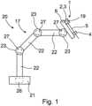
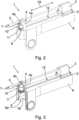
1 eine schematische Ansicht eines erfindungsgemäßen Roboterarms mit einem daran angeordneten erfindungsgemäßen Roboterarmeinrichtung in Form eines Linearaktuators als Werkzeugführungseinheit,2 eine erste schematische Perspektivdarstellung des Linearaktuators nach1 gemäß einer ersten Ausführungsform,3 eine zweite schematische Perspektivdarstellung des Linearaktuators nach1 und2 mit einem Teilausschnitt im Bereich eines Bedienkraftelements,4 eine schematische Perspektivdarstellung des Linearaktuators gemäß einer zweiten Ausführungsform,5 eine schematische Längsschnittdarstellung des Linearaktuators nach4 zur Veranschaulichung des Aufbaus des Linearaktuators im Bereich des Bedienkraftelements,6a eine erste schematische Längsschnittdarstellung des Linearaktuators gemäß einer dritten Ausführungsform zur Veranschaulichung des Aufbaus des Linearaktuators im Bereich des Bedienkraftelements, wobei der Linearaktuator in einem ersten Betriebszustand vorliegt, und6b eine zweite schematische Längsschnittdarstellung des Linearaktuators gemäß6a , wobei der Linearaktuator in einem zweiten Betriebszustand vorliegt.
1 a schematic view of a robot arm according to the invention with a robot arm device according to the invention arranged thereon in the form of a linear actuator as a tool guide unit,2 a first schematic perspective view of thelinear actuator 1 according to a first embodiment,3 a second schematic perspective view of thelinear actuator 1 and2 with a partial cutout in the area of an operating force element,4 a schematic perspective view of the linear actuator according to a second embodiment,5 a schematic longitudinal sectional representation of thelinear actuator 4 to illustrate the structure of the linear actuator in the area of the operating force element,6a a first schematic longitudinal sectional representation of the linear actuator according to a third embodiment to illustrate the structure of the linear actuator in the area of the operating force element, wherein the linear actuator is in a first operating state, and6b a second schematic longitudinal sectional representation of the linear actuator according to6a , wherein the linear actuator is in a second operating state.
Gemäß
Die Roboterarmeinrichtung bzw. der Linearaktuator 1 umfasst nach
Die Werkzeugaufnahme 4 führt das Werkzeug 5 bei Längsverlagerung des Linearschlittens 2 relativ zum Strukturelement 6 in axialer Richtung und leitet auf das Werkzeug 5 einwirkende Querkräfte in das Strukturelement 6 ab. Über die Werkzeugaufnahme 4 wird das Werkzeug 5 während der Längsverlagerung des Linearschlittens 2 also radial abgestützt.The
Nach den
Die Sensoreinheit 9 erfasst eine durch einen Nutzer auf das Betätigungselement 11 eingebrachte manuelle Betätigungskraft und übermittelt entsprechende Messdaten an die Steuereinheit 26. Diese Messdaten werden von der Steuereinheit 26 so verarbeitet, dass die Antriebe 27 des Roboterarms 17 ansteuerbar sind, um den Linearaktuator 1 in eine vom Nutzer gewünschte Position im Raum zu bewegen. Die Sensoreinheit 9 ist hier eine Kraft-Sensoreinheit, die auf das Betätigungselement 11 einwirkende Betätigungskräfte des Nutzers sensieren kann. Ein beispielhafter Aufbau der Sensoreinheit 9 ist in den Ausführungsbeispielen nach
Gemäß der ersten Ausführungsform nach
In dieser ersten Ausführungsform ist das Betätigungselement 11 als sogenannte „Spacemouse“ ausgebildet. Vorliegend weist das Betätigungselement 11 wenigstens einen Schalter 10 auf. Der Schalter 10 kann dazu vorgesehen sein, durch Betätigung einen Schaltzustand des Roboters 20 bzw. des Roboterarms 17 einzustellen oder zu ändern. Hier ist der Schalter 10 am Betätigungselement 11 angeordnet. Gemäß den Ausführungsformen nach den
In
Die Sensoreinheit 9 ist nach
Gemäß
Das Basiselement 4c nimmt den axialen Abschnitt 9b des Betätigungsstifts 9a räumlich auf bzw. umgibt diesen, wobei der axiale Abschnitt 9b des Betätigungsstifts 9a zu keiner Zeit am Basiselement 4c zur Anlage kommen.The
Das hier gemäß
Die
BezugszeichenlisteList of reference symbols
- 11
- LinearaktuatorLinear actuator
- 22
- Linearschlittenlinear slide
- 33
- WerkzeugträgerTool carrier
- 44
- WerkzeugaufnahmeTool holder
- 4a4a
- Trägercarrier
- 4b4b
- Erste AussparungFirst recess
- 4c4c
- BasiselementBasic element
- 4d4d
- Aufnahmekörperreceiving body
- 55
- WerkzeugTool
- 66
- StrukturelementStructural element
- 6a6a
- MontageöffnungAssembly opening
- 77
- Hohlraumcavity
- 88th
- BedieneinrichtungOperating device
- 99
- SensoreinheitSensor unit
- 9a9a
- BetätigungsstiftActuator pin
- 9b9b
- Axialer Abschnitt des BetätigungsstiftsAxial section of the actuation pin
- 9c9c
- Kugelförmiger Gelenkkopf des BetätigungsstiftsSpherical joint head of the actuating pin
- 9d9d
- GelenkaufnahmeJoint recording
- 1010
- SchalterSwitch
- 1111
- BetätigungselementActuator
- 11a11a
- Erstes Segment des BetätigungselementsFirst segment of the actuator
- 11b11b
- Zweites Segment des BetätigungselementsSecond segment of the actuator
- 11c11c
- Steg des BetätigungselementsBridge of the actuating element
- 1212
- FührungsschieneGuide rail
- 1313
- Durchbruchbreakthrough
- 1414
- Schraubescrew
- 1515
- Zweite AussparungSecond recess
- 1616
- Formelement des BasiselementsForm element of the base element
- 1717
- RoboterarmRobot arm
- 1818
- DeckelLid
- 1919
- AntriebseinheitDrive unit
- 2020
- Roboterrobot
- 2121
- BasisBase
- 2222
- RoboterarmsegmentRobot arm segment
- 2323
- Gelenkjoint
- 2424
- PfeilArrow
- 2525
- Rastelement des AufnahmekörpersLocking element of the receiving body
- 2626
- SteuereinheitControl unit
- 2727
- Antriebdrive
ZITATE ENTHALTEN IN DER BESCHREIBUNGQUOTES INCLUDED IN THE DESCRIPTION
Diese Liste der vom Anmelder aufgeführten Dokumente wurde automatisiert erzeugt und ist ausschließlich zur besseren Information des Lesers aufgenommen. Die Liste ist nicht Bestandteil der deutschen Patent- bzw. Gebrauchsmusteranmeldung. Das DPMA übernimmt keinerlei Haftung für etwaige Fehler oder Auslassungen.This list of documents listed by the applicant was generated automatically and is included solely for the better information of the reader. The list is not part of the German patent or utility model application. The DPMA assumes no liability for any errors or omissions.
Zitierte PatentliteraturCited patent literature
- EP 2332480 A2 [0002]EP 2332480 A2 [0002]
Claims (10)
Translated fromGermanPriority Applications (1)
| Application Number | Priority Date | Filing Date | Title |
|---|---|---|---|
| DE102023105701.4ADE102023105701A1 (en) | 2023-03-08 | 2023-03-08 | Robot arm device and robot arm with such a robot arm device |
Applications Claiming Priority (1)
| Application Number | Priority Date | Filing Date | Title |
|---|---|---|---|
| DE102023105701.4ADE102023105701A1 (en) | 2023-03-08 | 2023-03-08 | Robot arm device and robot arm with such a robot arm device |
Publications (1)
| Publication Number | Publication Date |
|---|---|
| DE102023105701A1true DE102023105701A1 (en) | 2024-03-28 |
Family
ID=90140296
Family Applications (1)
| Application Number | Title | Priority Date | Filing Date |
|---|---|---|---|
| DE102023105701.4ACeasedDE102023105701A1 (en) | 2023-03-08 | 2023-03-08 | Robot arm device and robot arm with such a robot arm device |
Country Status (1)
| Country | Link |
|---|---|
| DE (1) | DE102023105701A1 (en) |
Citations (5)
| Publication number | Priority date | Publication date | Assignee | Title |
|---|---|---|---|---|
| EP2332480A2 (en) | 2005-05-19 | 2011-06-15 | Intuitive Surgical Operations, Inc. | Software center and highly configurable robotic systems for surgery and other uses |
| DE102016011698A1 (en)* | 2015-10-02 | 2017-04-06 | Fanuc Corporation | Gripped robotic operating device for operating a robot |
| DE102015012962A1 (en)* | 2015-10-08 | 2017-04-13 | Sami Haddadin | robot system |
| DE102016222675A1 (en)* | 2016-11-17 | 2018-05-17 | Kuka Roboter Gmbh | Robot handheld device, associated coupling device, robot and method |
| DE102020206568B4 (en)* | 2020-05-26 | 2022-01-13 | Dr. Doll Engineering Gmbh | Programming system for manually programming a movement of an industrial robot, industrial robot with such a programming system and method for manually programming a movement of an industrial robot |
- 2023
- 2023-03-08DEDE102023105701.4Apatent/DE102023105701A1/ennot_activeCeased
Patent Citations (5)
| Publication number | Priority date | Publication date | Assignee | Title |
|---|---|---|---|---|
| EP2332480A2 (en) | 2005-05-19 | 2011-06-15 | Intuitive Surgical Operations, Inc. | Software center and highly configurable robotic systems for surgery and other uses |
| DE102016011698A1 (en)* | 2015-10-02 | 2017-04-06 | Fanuc Corporation | Gripped robotic operating device for operating a robot |
| DE102015012962A1 (en)* | 2015-10-08 | 2017-04-13 | Sami Haddadin | robot system |
| DE102016222675A1 (en)* | 2016-11-17 | 2018-05-17 | Kuka Roboter Gmbh | Robot handheld device, associated coupling device, robot and method |
| DE102020206568B4 (en)* | 2020-05-26 | 2022-01-13 | Dr. Doll Engineering Gmbh | Programming system for manually programming a movement of an industrial robot, industrial robot with such a programming system and method for manually programming a movement of an industrial robot |
Similar Documents
| Publication | Publication Date | Title |
|---|---|---|
| EP2862677B1 (en) | Method for handling objects using at least two industrial robots | |
| EP2868445B1 (en) | Method for programming sequences of movements of a redundant industrial robot and associated industrial robot | |
| EP3217909B1 (en) | Intelligent holding arm for head surgery with touch-sensitive operation | |
| DE102008062622B4 (en) | Method and device for entering commands into a controller of a manipulator | |
| DE102014216514B3 (en) | Method for programming an industrial robot and associated industrial robots | |
| EP1950010B1 (en) | Robot and method for programming a robot | |
| DE10392966B4 (en) | Parallel haptic joystick device | |
| DE102018007842B4 (en) | Control device for monitoring the direction of movement of an operating tool | |
| DE102007026299B4 (en) | Industrial robots and method for programming an industrial robot | |
| EP2359205A1 (en) | Method and device for inputting commands into a control of a manipulator | |
| WO2014127966A1 (en) | Holding device for a surgical instrument and a sheath and method and control device for operating a robot with such a holding device | |
| EP2392435A2 (en) | Tool handling system and method for manipulating workpieces by means of cooperating manipulators | |
| DE102013218823A1 (en) | Method for manually adjusting the pose of a manipulator arm of an industrial robot and associated industrial robots | |
| EP3416787A1 (en) | Effector unit for a robot, work implement comprising a robot, and method for replacing an effector in robots | |
| WO2005046499A2 (en) | Actuator platform for guiding end effectors in minimally invasive interventions | |
| DE102008041260A1 (en) | Method for operating a medical robot, medical robot and medical workstation | |
| EP3629971A1 (en) | Robotic manipulator for guiding an endoscope, having parallel kinematics | |
| DE102021205856B4 (en) | Method of operating a manipulator | |
| DE102015117306B4 (en) | Multi-axis mouse for a multi-axis robot | |
| DE102023105701A1 (en) | Robot arm device and robot arm with such a robot arm device | |
| DE102021129897B4 (en) | Modular robot device and method for operating a modular robot device | |
| DE102020108513B4 (en) | Human-robot collaboration facility | |
| DE102015101616B3 (en) | Hybrid kinematics for positioning an inspection system | |
| DE102015003941A1 (en) | Controlling a mobile redundant robot | |
| EP1684159A2 (en) | Mobile haptic interface |
Legal Events
| Date | Code | Title | Description |
|---|---|---|---|
| R012 | Request for examination validly filed | ||
| R016 | Response to examination communication | ||
| R230 | Request for early publication | ||
| R002 | Refusal decision in examination/registration proceedings | ||
| R003 | Refusal decision now final |