DE102022130600A1 - Handle arrangement of a motor vehicle - Google Patents
Handle arrangement of a motor vehicleDownload PDFInfo
- Publication number
- DE102022130600A1 DE102022130600A1DE102022130600.3ADE102022130600ADE102022130600A1DE 102022130600 A1DE102022130600 A1DE 102022130600A1DE 102022130600 ADE102022130600 ADE 102022130600ADE 102022130600 A1DE102022130600 A1DE 102022130600A1
- Authority
- DE
- Germany
- Prior art keywords
- door handle
- handle
- longitudinal end
- door
- lever
- Prior art date
- Legal status (The legal status is an assumption and is not a legal conclusion. Google has not performed a legal analysis and makes no representation as to the accuracy of the status listed.)
- Pending
Links
- 230000033001locomotionEffects0.000claimsabstractdescription55
- 230000008878couplingEffects0.000claimsdescription21
- 238000010168coupling processMethods0.000claimsdescription21
- 238000005859coupling reactionMethods0.000claimsdescription21
- 230000001133accelerationEffects0.000claimsdescription6
- 230000007935neutral effectEffects0.000claimsdescription6
- 238000000034methodMethods0.000description3
- 230000008569processEffects0.000description3
- 238000009434installationMethods0.000description2
- 238000013459approachMethods0.000description1
- 238000013461designMethods0.000description1
- 238000011161developmentMethods0.000description1
- 230000018109developmental processEffects0.000description1
- 230000007246mechanismEffects0.000description1
- 238000012986modificationMethods0.000description1
- 230000004048modificationEffects0.000description1
Images


Classifications
- E—FIXED CONSTRUCTIONS
- E05—LOCKS; KEYS; WINDOW OR DOOR FITTINGS; SAFES
- E05B—LOCKS; ACCESSORIES THEREFOR; HANDCUFFS
- E05B85/00—Details of vehicle locks not provided for in groups E05B77/00 - E05B83/00
- E05B85/10—Handles
- E05B85/107—Pop-out handles, e.g. sliding outwardly before rotation
- E—FIXED CONSTRUCTIONS
- E05—LOCKS; KEYS; WINDOW OR DOOR FITTINGS; SAFES
- E05B—LOCKS; ACCESSORIES THEREFOR; HANDCUFFS
- E05B77/00—Vehicle locks characterised by special functions or purposes
- E05B77/02—Vehicle locks characterised by special functions or purposes for accident situations
- E05B77/04—Preventing unwanted lock actuation, e.g. unlatching, at the moment of collision
- E05B77/06—Preventing unwanted lock actuation, e.g. unlatching, at the moment of collision by means of inertial forces
- E—FIXED CONSTRUCTIONS
- E05—LOCKS; KEYS; WINDOW OR DOOR FITTINGS; SAFES
- E05B—LOCKS; ACCESSORIES THEREFOR; HANDCUFFS
- E05B81/00—Power-actuated vehicle locks
- E05B81/54—Electrical circuits
- E05B81/90—Manual override in case of power failure
- E—FIXED CONSTRUCTIONS
- E05—LOCKS; KEYS; WINDOW OR DOOR FITTINGS; SAFES
- E05B—LOCKS; ACCESSORIES THEREFOR; HANDCUFFS
- E05B85/00—Details of vehicle locks not provided for in groups E05B77/00 - E05B83/00
- E05B85/10—Handles
- E05B85/103—Handles creating a completely closed wing surface
Landscapes
- Lock And Its Accessories (AREA)
Abstract
Translated fromGerman
Description
Translated fromGermanDie Erfindung betrifft eine Griffanordnung eines Kraftfahrzeugs, aufweisend ein an einer Fahrzeugtür befestigbares Trägerelement, ein an dem Trägerelement zwischen einer Grundstellung und einer Ausstellstellung gelagertes Antriebselement, einen Türgriff, welcher eine Einfahrstellung, in welcher der Türgriff strakbündig mit der Außenseite der Fahrzeugtür verlaufend angeordnet ist, und in einem Normalbetrieb mit Hilfe des Antriebselements eine Bereitschaftsstellung, in welcher der Türgriff zur Betätigung gegenüber der Außenseite der Fahrzeugtür in eine Ausstellrichtung ausgestellt angeordnet ist, einnehmen kann und welcher ein erstes Längsende und ein zweites Längsende aufweist.The invention relates to a handle arrangement of a motor vehicle, having a carrier element that can be fastened to a vehicle door, a drive element mounted on the carrier element between a basic position and an extended position, a door handle that can assume a retracted position in which the door handle is arranged flush with the outside of the vehicle door, and in normal operation with the aid of the drive element a standby position in which the door handle is arranged in an extended direction relative to the outside of the vehicle door for actuation, and which has a first longitudinal end and a second longitudinal end.
Derartige Griffanordnungen mit einem in einer Einfahrstellung strakbündig bzw. flächenbündig angeordneten und in einer Bereitschaftsstellung parallel zu der Außenseite ausgestellt angeordneten Türgriff sind aus dem Stand der Technik bekannt. In einem Normalbetrieb bewegt dabei das Antriebselement einen an dem Trägerelement gelagerten und mit dem ersten Längsende des Türgriffs verbundenen Antriebshebel, um den Türgriff in seine Bereitschaftsposition auszufahren, in welcher ein Benutzer den Türgriff dann zur Öffnung einer Fahrzeugtür manuell betätigen kann. Dabei ist das zweite Längsende des Türgriffs meist mit einem mehrteilig aufgebauten Hebelsystem verbunden, welches dafür sorgt, dass das zweite Längsende des Türgriffs der Bewegung des ersten Längsendes folgt und ebenfalls ausfährt. Das Hebelsystem ist hierbei von dem Antriebshebel entkoppelt, so dass bei einem Fahrzeugunfall stets die Gefahr besteht, dass aufgrund einer bei dem Fahrzeugunfall erzeugten Beschleunigungskraft der Türgriff in eine Position gelangt, in welcher eine unerwünschte Öffnung der Fahrzeugtür erfolgt. Aus diesem Grund sind Sperren und Ausgleichsgewichte bei bekannten Griffanordnungen vorgesehen, welche die Anzahl der Bauteile und damit die Kosten in die Höhe treiben und welche den erforderlichen Einbauraum der Griffanordnung in nachteiliger Weise erhöht.Such handle arrangements with a door handle that is arranged flush or flush with the surface in a retracted position and arranged parallel to the outside in a standby position are known from the prior art. In normal operation, the drive element moves a drive lever that is mounted on the carrier element and connected to the first longitudinal end of the door handle in order to extend the door handle into its standby position, in which a user can then manually operate the door handle to open a vehicle door. The second longitudinal end of the door handle is usually connected to a multi-part lever system that ensures that the second longitudinal end of the door handle follows the movement of the first longitudinal end and also extends. The lever system is decoupled from the drive lever, so that in the event of a vehicle accident there is always a risk that the acceleration force generated during the vehicle accident will cause the door handle to end up in a position in which the vehicle door is opened undesirably. For this reason, locks and counterweights are provided in known handle arrangements, which increase the number of components and thus the costs and which disadvantageously increase the required installation space of the handle arrangement.
Aufgabe der Erfindung ist es daher, eine Griffanordnung eines Kraftfahrzeugs bereitzustellen, bei welcher die vorstehend genannten Nachteile vermieden werden und welche sich dennoch durch eine hohe Sicherheit im Fall eines Fahrzeugunfalls auszeichnet.The object of the invention is therefore to provide a handle arrangement of a motor vehicle in which the above-mentioned disadvantages are avoided and which is nevertheless characterized by a high level of safety in the event of a vehicle accident.
Diese Aufgabe wird erfindungsgemäß gelöst durch eine Einstellvorrichtung mit den Merkmalen gemäß dem Anspruch 1.This object is achieved according to the invention by an adjustment device having the features according to claim 1.
Die erfindungsgemäße Griffanordnung eines Kraftfahrzeugs weist ein an einer Fahrzeugtür befestigbares Trägerelement, ein an dem Trägerelement zwischen einer Grundstellung und einer Ausstellstellung gelagertes Antriebselement, einen Türgriff, welcher eine Einfahrstellung, in welcher der Türgriff strakbündig mit der Außenseite der Fahrzeugtür verlaufend angeordnet ist, und in einem Normalbetrieb mit Hilfe des Antriebselements eine Bereitschaftsstellung, in welcher der Türgriff zur Betätigung gegenüber einer Außenseite der Fahrzeugtür in eine Ausstellrichtung ausgestellt angeordnet ist, einnehmen kann und welcher ein erstes Längsende und ein zweites Längsende aufweist, einen mit dem Antriebselement bewegungsgekoppelten und an dem Trägerelement zwischen einer Ruhestellung, in welcher der Türgriff in seiner Einfahrstellung angeordnet ist, und einer Ausfahrstellung, in welcher der Türgriff in seiner Bereitschaftsstellung angeordnet ist, bewegbar gelagerten Antriebshebel und einen an dem Trägerelement schwenkbar gelagerten Bewegungshebel auf, mit welchem das zweite Längsende des Türgriffs verbunden ist und welcher mit dem Antriebshebel bewegungsgekoppelt ist. Der Türgriff ist zur manuellen Betätigung an seinem ersten Längsende über eine Schwenkachse derart drehbar an dem Antriebshebel und/oder derart relativ zu dem Antriebshebel verschwenkbar gelagert, dass das zweite Längsende in Ausstellrichtung verschwenkbar ausgestellt anordenbar ist.The handle arrangement of a motor vehicle according to the invention has a carrier element that can be fastened to a vehicle door, a drive element mounted on the carrier element between a basic position and an extended position, a door handle that can assume a retracted position in which the door handle is arranged flush with the outside of the vehicle door and, in normal operation with the aid of the drive element, a standby position in which the door handle is arranged in an extended direction relative to an outside of the vehicle door for actuation, and which has a first longitudinal end and a second longitudinal end, a drive lever that is motion-coupled to the drive element and movably mounted on the carrier element between a rest position in which the door handle is arranged in its retracted position and an extended position in which the door handle is arranged in its ready position, and a movement lever that is pivotably mounted on the carrier element, to which the second longitudinal end of the door handle is connected and which is motion-coupled to the drive lever. For manual operation, the door handle is mounted at its first longitudinal end via a pivot axis so as to be rotatable on the drive lever and/or pivotable relative to the drive lever in such a way that the second longitudinal end can be arranged pivotably in the opening direction.
Vorteilhafte und zweckmäßige Ausgestaltungen und Weiterbildungen der Erfindung ergeben sich aus den entsprechenden Unteransprüchen.Advantageous and expedient embodiments and further developments of the invention emerge from the corresponding subclaims.
Durch die Erfindung wird eine Griffanordnung eines Kraftfahrzeugs zur Verfügung gestellt, welche sich durch einen funktionsgerechten und kostengünstigen Aufbau auszeichnet und welche ein hohes Maß an Funktionalität aufweist. Dadurch, dass das erste Längsende des Türgriffs um die Schwenkachse rotierbar bzw. drehbar gelagert ist und relativ zu dem Antriebshebel bewegt werden kann, erfolgt die manuelle Handhabung des Türgriffs nach Art eines Rotationstürgriffs, bei welchem zur Öffnung der Fahrzeugtür ein Benutzer an dem Türgriff zieht und dadurch das zweite Längsende ausgeschwenkt wird, bis die Öffnung der Fahrzeugtür erfolgt. Dabei erfolgt dieser manuelle Öffnungsvorgang sowohl in einem Normalbetrieb als auch in einem stromlosen Notbetrieb der Griffanordnung, so dass auf vorteilhafte Weise identische Bauteile für den Öffnungsvorgang verwendet werden und damit die Anzahl der Bauteile auf ein Minimum beschränkt wird.The invention provides a handle arrangement of a motor vehicle which is characterized by a functional and cost-effective design and which has a high degree of functionality. Because the first longitudinal end of the door handle is mounted so that it can rotate or pivot about the pivot axis and can be moved relative to the drive lever, the manual handling of the door handle takes place in the manner of a rotary door handle, in which a user pulls on the door handle to open the vehicle door and the second longitudinal end is thereby pivoted out until the vehicle door is opened. This manual opening process takes place both in normal operation and in a power-free emergency operation of the handle arrangement, so that identical components are advantageously used for the opening process and the number of components is thus kept to a minimum.
Im Hinblick auf die Sicherheit der Griffanordnung im Fall eines Fahrzeugunfalls sieht die Erfindung in Ausgestaltung vor, dass das Antriebselement in seiner Grundstellung den Antriebshebel in seiner Ruhestellung haltend ausgebildet ist. Das Antriebselement ist eine Bewegung des Antriebshebels aus seiner Ruhestellung heraus blockierend ausgebildet, so dass der Türgriff in seinem eingefahrenen Zustand bzw. in seiner Einfahrstellung festgehalten ist.With regard to the safety of the handle arrangement in the event of a vehicle accident, the invention provides that the drive element is designed to hold the drive lever in its rest position in its basic position. The drive element is designed to block movement of the drive lever from its rest position. designed so that the door handle is held in its retracted state or in its retracted position.
Für einen minimalen Bauraum sieht die Erfindung in weiterer Ausgestaltung vor, dass das Antriebselement eine nach Art eines Exzenters ausgebildete Steuerscheibe, welche bei einer Bewegung des Antriebselements aus der Grundstellung in die Ausstellstellung den Antriebshebel aus seiner Ruhestellung in die Ausfahrstellung drängend ausgebildet ist, und einen Sperrhaken, welcher in der Grundstellung des Antriebselements mit dem Antriebshebel in Eingriff steht und welcher in der Ausstellstellung des Antriebselements außer Eingriff mit dem Antriebshebel steht, aufweist. Folglich ist das Antriebselement zum Bewegen des Antriebshebels und zum Sperren des Antriebshebels ausgebildet.In order to minimize installation space, the invention provides in a further embodiment that the drive element has a control disc designed in the manner of an eccentric, which is designed to force the drive lever from its rest position into the extended position when the drive element moves from the basic position to the extended position, and a locking hook which is in engagement with the drive lever in the basic position of the drive element and which is out of engagement with the drive lever in the extended position of the drive element. Consequently, the drive element is designed to move the drive lever and to lock the drive lever.
Wenngleich die rotatorische Handhabung des Türgriffs bei der erfindungsgemäßen Griffanordnung sowohl im Fall eines Normalbetriebs als auch im Fall eines stromlosen Notbetriebs, bei welchem der Türgriff nicht in seine Bereitschaftsstellung motorisch bewegt werden kann, identisch ist, so ist die Stellung des Türgriffs je nach Fall unterschiedlich. Die Erfindung sieht in Ausgestaltung vor, dass in einem Normalbetrieb bei einer manuellen Betätigung der Türgriff aus seiner Bereitschaftsstellung in eine Betätigungsstellung, in welcher das zweite Längsende des ausgefahrenen Türgriffs um die Schwenkachse nach Art eines Rotationstürgriffs ausgeschwenkt angeordnet ist, bewegt wird. Hingegen ist in einem Notbetrieb der Türgriff aus der Einfahrstellung in eine Kippstellung bewegbar, in welcher das erste Längsende des eingefahrenen Türgriffs um die Schwenkachse rotiert bzw. gedreht angeordnet ist und in welcher das zweite Längsende aus der Außenseite hervorstehend in Richtung der Ausstellrichtung ausgeschwenkt angeordnet ist, wobei in der Kippstellung der Türgriff zumindest abschnittsweise von einem Benutzer hintergreifbar angeordnet ist.Although the rotary handling of the door handle in the handle arrangement according to the invention is identical both in the case of normal operation and in the case of power-free emergency operation, in which the door handle cannot be moved into its ready position by motor, the position of the door handle varies depending on the case. In one embodiment, the invention provides that in normal operation, when manually operated, the door handle is moved from its ready position into an actuated position in which the second longitudinal end of the extended door handle is arranged so that it is pivoted out about the pivot axis in the manner of a rotary door handle. In contrast, in emergency operation, the door handle can be moved from the retracted position into a tilted position in which the first longitudinal end of the retracted door handle is arranged so that it is rotated or turned about the pivot axis and in which the second longitudinal end is arranged so that it protrudes from the outside and is pivoted out in the direction of the opening direction, wherein in the tilted position the door handle is arranged so that a user can reach behind it at least in sections.
Für den Fall, bei welchen das Öffnen der Fahrzeugtür sowohl in dem Normalbetrieb als auch in dem Notbetrieb über eine entsprechende Mechanik erfolgt, sieht die Erfindung in weiterer Ausgestaltung vor, dass an dem Trägerelement ein mechanisches Türöffnungselement schwenkbar gelagert ist, wobei bei einer Ausschwenkbewegung des zweiten Längsendes des Türgriffs der Bewegungshebel das mechanische Türöffnungselement aus einer Neutralstellung in eine die Fahrzeugtür öffnende Öffnungsstellung drängend ausgebildet ist.In the case where the vehicle door is opened both in normal operation and in emergency operation via a corresponding mechanism, the invention provides in a further embodiment that a mechanical door opening element is pivotally mounted on the carrier element, wherein when the second longitudinal end of the door handle pivots out, the movement lever is designed to urge the mechanical door opening element from a neutral position into an opening position that opens the vehicle door.
Von besonderem Vorteil ist es in Ausgestaltung der Erfindung, wenn der Antriebshebel und der Bewegungshebel über ein Koppelgestänge bewegungskoppelt miteinander verbunden sind. Auf diese Weise liegt ein gekoppeltes System vor, so dass bei Blockierung einer Bewegung des Antriebshebels gleichzeitig auch eine Bewegung des Bewegungshebels gesperrt ist, so dass der Türgriff in seiner eingefahrenen Einfahrstellung gegenüber etwaigen Beschleunigungskräften im Fall eines Fahrzeugunfalls sicher fixiert ist.It is particularly advantageous in an embodiment of the invention if the drive lever and the movement lever are connected to one another via a coupling rod. In this way, a coupled system is present, so that if a movement of the drive lever is blocked, a movement of the movement lever is also blocked at the same time, so that the door handle is securely fixed in its retracted position against any acceleration forces in the event of a vehicle accident.
Die Erfindung sieht in weiterer Ausgestaltung vor, dass das Koppelgestänge an einem Längsende, welches mit dem Antriebshebel bewegungsgekoppelt ist, eine Führungsausnehmung aufweist, in welcher ein an dem Antriebshebel ausgebildeter Achszapfen angeordnet ist, wobei in einem Notbetrieb die Führungsausnehmung eine Bewegung des Bewegungshebels bei einer Bewegung des Türgriffs aus einer Kippstellung in eine Notbetätigungsstellung erlaubend ausgebildet ist. Die Bewegungskopplung über das Koppelgestänge weist somit einen Freiheitsgrad auf, welcher aber lediglich bei einem Notbetrieb und nicht bei einem Normalbetrieb wirksam wird.In a further embodiment, the invention provides that the coupling rod has a guide recess at a longitudinal end, which is coupled in motion to the drive lever, in which an axle pin formed on the drive lever is arranged, wherein in an emergency operation the guide recess is designed to allow a movement of the movement lever when the door handle moves from a tilt position to an emergency actuation position. The movement coupling via the coupling rod thus has a degree of freedom, which, however, only becomes effective in an emergency operation and not in a normal operation.
Schließlich sieht die Erfindung in Ausgestaltung vor, dass der Bewegungshebel ein Massenausgleichselement aufweist, welches im Crashfall einer auf den Türgriff wirkenden Beschleunigungskraft entgegenwirkend und den in dem Normalbetrieb in seiner Bereitschaftsstellung angeordneten Türgriff in seiner Bereitschaftsstellung haltend ausgebildet ist.Finally, the invention provides in one embodiment that the movement lever has a mass balancing element which, in the event of a crash, is designed to counteract an acceleration force acting on the door handle and to hold the door handle, which is arranged in its standby position during normal operation, in its standby position.
Es versteht sich, dass die vorstehend genannten und nachstehenden noch zu erläuternden Merkmale nicht nur in der jeweils angegebenen Kombination, sondern auch in anderen Kombinationen oder in Alleinstellung verwendbar sind, ohne den Rahmen der vorliegenden Erfindung zu verlassen. Der Rahmen der Erfindung ist nur durch die Ansprüche definiert.It is understood that the features mentioned above and those still to be explained below can be used not only in the combination specified in each case, but also in other combinations or on their own, without departing from the scope of the present invention. The scope of the invention is defined only by the claims.
Weitere Einzelheiten, Merkmale und Vorteile des Gegenstandes der Erfindung ergeben sich aus der nachfolgenden Beschreibung im Zusammenhang mit der Zeichnung, in der ein beispielhaftes bevorzugtes Ausführungsbeispiel der Erfindung dargestellt ist.Further details, features and advantages of the subject matter of the invention emerge from the following description in conjunction with the drawing, in which an exemplary preferred embodiment of the invention is shown.
In der Zeichnung zeigt:
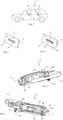
1 eine schematische Seitenansicht eines Kraftfahrzeugs mit mehreren erfindungsgemäßen Griffanordnungen,2 eine perspektivische Ansicht der erfindungsgemäßen Griffanordnung mit einem in einer Einfahrstellung strakbündig bzw. flächenbündig mit einer Außenseite einer Fahrzeugtür verlaufend angeordneten Türgriff,3 eine Perspektivansicht der erfindungsgemäßen Griffanordnung mit dem in einer Ausfahrstellung und gegenüber der Außenseite der Fahrzeugtür ausgestellt angeordneten Türgriff,4 eine perspektivische Vorderansicht auf die erfindungsgemäße Griffanordnung,5 eine perspektivische Rückansicht auf die erfindungsgemäße Griffanordnung,6 eine Draufsicht auf die erfindungsgemäße Griffanordnung, bei welcher der Türgriff in einer Einfahrstellung angeordnet ist,7 eine Draufsicht auf die erfindungsgemäße Griffanordnung in einem Normalbetrieb, bei welcher der Türgriff in einer Bereitschaftsstellung angeordnet ist,8 eine Draufsicht auf die erfindungsgemäße Griffanordnung in einem Normalbetrieb, bei welcher der Türgriff in einer zur Öffnung einer Fahrzeugtür dienenden Betätigungsstellung angeordnet ist,9 eine Draufsicht auf die erfindungsgemäße Griffanordnung in einem Notbetrieb, bei welcher der Türgriff in einer Kippstellung angeordnet ist,10 eine Draufsicht auf die erfindungsgemäße Griffanordnung in einem Notbetrieb, bei welcher der Türgriff in einer zur Öffnung einer Fahrzeugtür dienenden Notbetätigungsstellung angeordnet ist, und11 eine perspektivische Seitenansicht auf die erfindungsgemäße Griffanordnung für einen Türöffnungsvorgang.
1 a schematic side view of a motor vehicle with several handle arrangements according to the invention,2 a perspective view of the handle arrangement according to the invention with a door handle arranged in a retracted position flush or flush with the outside of a vehicle door,3 a perspective view of the handle arrangement according to the invention with the in a driving position and door handle positioned opposite the outside of the vehicle door,4 a perspective front view of the handle arrangement according to the invention,5 a perspective rear view of the handle arrangement according to the invention,6 a plan view of the handle arrangement according to the invention, in which the door handle is arranged in a retracted position,7 a plan view of the handle arrangement according to the invention in normal operation, in which the door handle is arranged in a standby position,8th a plan view of the handle arrangement according to the invention in normal operation, in which the door handle is arranged in an actuating position for opening a vehicle door,9 a plan view of the handle arrangement according to the invention in an emergency mode, in which the door handle is arranged in a tilted position,10 a plan view of the handle arrangement according to the invention in an emergency operation, in which the door handle is arranged in an emergency operating position for opening a vehicle door, and11 a perspective side view of the handle arrangement according to the invention for a door opening process.
In der
Die
Nachstehend wird Bezug auf die
Der drehbar um die Drehachse 18 gelagerte Antriebshebel 10 und das erste Längsende 8 des Türgriffs 4 sind über eine Schwenkachse 19 miteinander gelenkig verbunden, so dass der Türgriff 4 an seinem ersten Längsende 8 relativ zu dem Antriebshebel 10 drehbar ist. Das zweite Längsende 9 des Türgriffs 4 ist mit dem Bewegungshebel 11 gekoppelt. Der Bewegungshebel 11 ist dabei um eine Achse 20 drehbar an dem Trägerelement 6 gelagert. Das freie Ende des Bewegungshebels 11 weist einen Kopplungszapfen 21 auf, welcher in einer an dem zweiten Längsende 9 des Türgriffs 4 ausgebildeten Aussparung 22 bewegbar geführt ist, so dass das zweite Längsende 9 des Türgriffs 4 und der Bewegungshebel 11 relativ zueinander bewegbar sind, wobei diese Bewegung eine rotatorische und/oder aufgrund der Aussparung 22 eine lineare Bewegung sein kann.The
Wie den
Nachstehend wird die Funktionsweise der erfindungsgemäßen Griffanordnung 3 beschrieben.The operation of the
Die
In
In
In der Bereitschaftsstellung des Türgriffs 4 kann ein Benutzer den Türgriff 4 nun hintergreifen und betätigen, wobei eine durch den Benutzer auf den Türgriff 4 ausgeübte Ziehkraft dazu führt, dass der Türgriff 4 in seine Betätigungsstellung gelangt, die in
Die
Vorstehend wurde eine Griffanordnung 3 beschrieben, welche ein gekoppeltes System aus Hebeln 10 und 11 und Gestänge 12 darstellt, wobei sowohl in einem Normalbetrieb als auch in einem Notbetrieb der Türgriff 4 zur manuellen Betätigung an seinem ersten Längsende 8 über die Schwenkachse 19 derart drehbar an dem Antriebshebel 10 und derart relativ zu dem Antriebshebel 10 verschwenkbar gelagert ist, dass das zweite Längsende 9 des Türgriffs 4 in die Ausstellrichtung 14 verschwenkbar anordenbar ist.A
Die vorstehend beschriebene Erfindung ist selbstverständlich nicht auf die beschriebene und dargestellte Ausführungsform beschränkt. Es ist ersichtlich, dass an der in der Zeichnung dargestellten Ausführungsform zahlreiche, dem Fachmann entsprechend der beabsichtigten Anwendung naheliegende Abänderungen vorgenommen werden können, ohne dass dadurch der Bereich der Erfindung verlassen wird. Zur Erfindung gehört alles dasjenige, was in der Beschreibung enthalten und/oder in der Zeichnung dargestellt ist, einschließlich dessen, was abweichend von dem konkreten Ausführungsbeispiel für den Fachmann naheliegt.The invention described above is of course not limited to the embodiment described and shown. It is clear that numerous modifications that are obvious to a person skilled in the art according to the intended application can be made to the embodiment shown in the drawing without thereby departing from the scope of the invention. The invention includes everything that is contained in the description and/or shown in the drawing, including what deviates from the specific embodiment and is obvious to a person skilled in the art.
BezugszeichenlisteList of reference symbols
- 11
- KraftfahrzeugMotor vehicle
- 22
- FahrzeugtürVehicle door
- 33
- GriffanordnungHandle arrangement
- 44
- TürgriffDoor handle
- 55
- AußenseiteOutside
- 66
- TrägerelementSupport element
- 77
- AntriebselementDrive element
- 88th
- erstes Längsende von 4first longitudinal end of 4
- 99
- zweites Längsende von 4second longitudinal end of 4
- 1010
- AntriebshebelDrive lever
- 1111
- BewegungshebelMovement lever
- 1212
- KoppelgestängeCoupling rods
- 1414
- AusstellrichtungOpening direction
- 1515
- SteuerscheibeControl disc
- 1616
- BetätigungsansatzActuation approach
- 1717
- SperrhakenLocking hook
- 1818
- DrehachseRotation axis
- 1919
- SchwenkachseSwivel axis
- 2020
- Achseaxis
- 2121
- Kopplungszapfen von 11Coupling pin of 11
- 2222
- AussparungRecess
- 2323
- Längsende von 12Longitudinal end of 12
- 2424
- FührungsausnehmungGuide recess
- 2525
- AchszapfenAxle journal
- 2626
- MassenausgleichselementMass balancing element
- 2727
- mechanisches Türöffnungselementmechanical door opening element
Claims (9)
Translated fromGermanPriority Applications (2)
| Application Number | Priority Date | Filing Date | Title |
|---|---|---|---|
| DE102022130600.3ADE102022130600A1 (en) | 2022-11-18 | 2022-11-18 | Handle arrangement of a motor vehicle |
| EP23189948.5AEP4372191A1 (en) | 2022-11-18 | 2023-08-07 | Handle assembly of a motor vehicle |
Applications Claiming Priority (1)
| Application Number | Priority Date | Filing Date | Title |
|---|---|---|---|
| DE102022130600.3ADE102022130600A1 (en) | 2022-11-18 | 2022-11-18 | Handle arrangement of a motor vehicle |
Publications (1)
| Publication Number | Publication Date |
|---|---|
| DE102022130600A1true DE102022130600A1 (en) | 2024-05-23 |
Family
ID=87557714
Family Applications (1)
| Application Number | Title | Priority Date | Filing Date |
|---|---|---|---|
| DE102022130600.3APendingDE102022130600A1 (en) | 2022-11-18 | 2022-11-18 | Handle arrangement of a motor vehicle |
Country Status (2)
| Country | Link |
|---|---|
| EP (1) | EP4372191A1 (en) |
| DE (1) | DE102022130600A1 (en) |
Family Cites Families (7)
| Publication number | Priority date | Publication date | Assignee | Title |
|---|---|---|---|---|
| DE102013112706A1 (en)* | 2013-11-18 | 2015-05-21 | Illinois Tool Works Inc. | System comprising a door handle and an actuating device for the door handle |
| JP6957390B2 (en)* | 2018-03-09 | 2021-11-02 | 株式会社アルファ | Vehicle door handle device |
| CN108843162A (en)* | 2018-08-10 | 2018-11-20 | 宁波华德汽车零部件有限公司 | A kind of concealed automobile door handle |
| DE102019215078A1 (en)* | 2018-10-02 | 2020-04-02 | Magna Mirrors Of America, Inc. | FLOOR-MOUNTED DOOR HANDLE FOR A VEHICLE |
| KR102104888B1 (en)* | 2019-01-24 | 2020-04-27 | 주식회사 프라코 | Auto flush outside door handle assembly for vehicle |
| KR102276967B1 (en)* | 2020-03-18 | 2021-07-13 | 주식회사 프라코 | Auto flush outside door handle assembly for vehicle |
| US11746575B2 (en)* | 2020-07-16 | 2023-09-05 | Magna Mirrors Of America, Inc. | Vehicular door handle with manual override stop |
- 2022
- 2022-11-18DEDE102022130600.3Apatent/DE102022130600A1/enactivePending
- 2023
- 2023-08-07EPEP23189948.5Apatent/EP4372191A1/enactivePending
Also Published As
| Publication number | Publication date |
|---|---|
| EP4372191A1 (en) | 2024-05-22 |
Similar Documents
| Publication | Publication Date | Title |
|---|---|---|
| DE102005006580B4 (en) | hinge assembly | |
| EP3688259B1 (en) | Door handle assembly of a vehicle door | |
| EP3688258B1 (en) | Door handle assembly of a vehicle door | |
| EP1606136B1 (en) | Device for connecting a vehicle seat to a vehicle floor | |
| DE60129259T2 (en) | locking device | |
| DE102018207046A1 (en) | Seat adjustment for vehicle seat | |
| EP3803005A1 (en) | Door handle arrangement for a motor vehicle | |
| EP3803006A1 (en) | Door handle assembly for a motor vehicle | |
| DE102019002333A1 (en) | Cooling air control system for a motor vehicle | |
| DE102022130600A1 (en) | Handle arrangement of a motor vehicle | |
| DE102020112935A1 (en) | Motor vehicle door handle assembly | |
| EP3870785B1 (en) | Motor vehicle lock, in particular motor vehicle door lock | |
| DE102018214096B4 (en) | Center console for a vehicle, as well as vehicle with a center console | |
| DE102023113424A1 (en) | motor vehicle handle arrangement | |
| DE102022130601A1 (en) | Handle arrangement of a motor vehicle | |
| DE102023113429A1 (en) | motor vehicle movement safety mechanism | |
| DE102023113428A1 (en) | motor vehicle handle arrangement | |
| DE102023125173A1 (en) | Motor vehicle lock for a locking element of a motor vehicle | |
| DE102022113045A1 (en) | Motor vehicle lock | |
| DE102024110267A1 (en) | Adjustment arrangement for adjusting a closure element of a motor vehicle | |
| DE102023127982A1 (en) | Door handle arrangement | |
| DE102022122496A1 (en) | Motor vehicle lock | |
| DE102022113051A1 (en) | Motor vehicle lock, especially motor vehicle door lock | |
| DE102023131478A1 (en) | Motor vehicle lock | |
| DE102023117383A1 (en) | Drive arrangement for a flap of a motor vehicle with a body |