DE102022119571A1 - Notification control device for a vehicle - Google Patents
Notification control device for a vehicleDownload PDFInfo
- Publication number
- DE102022119571A1 DE102022119571A1DE102022119571.6ADE102022119571ADE102022119571A1DE 102022119571 A1DE102022119571 A1DE 102022119571A1DE 102022119571 ADE102022119571 ADE 102022119571ADE 102022119571 A1DE102022119571 A1DE 102022119571A1
- Authority
- DE
- Germany
- Prior art keywords
- vehicle
- satisfied
- condition
- oncoming
- period
- Prior art date
- Legal status (The legal status is an assumption and is not a legal conclusion. Google has not performed a legal analysis and makes no representation as to the accuracy of the status listed.)
- Granted
Links
Images


Classifications
- B—PERFORMING OPERATIONS; TRANSPORTING
- B60—VEHICLES IN GENERAL
- B60W—CONJOINT CONTROL OF VEHICLE SUB-UNITS OF DIFFERENT TYPE OR DIFFERENT FUNCTION; CONTROL SYSTEMS SPECIALLY ADAPTED FOR HYBRID VEHICLES; ROAD VEHICLE DRIVE CONTROL SYSTEMS FOR PURPOSES NOT RELATED TO THE CONTROL OF A PARTICULAR SUB-UNIT
- B60W50/00—Details of control systems for road vehicle drive control not related to the control of a particular sub-unit, e.g. process diagnostic or vehicle driver interfaces
- B60W50/08—Interaction between the driver and the control system
- B60W50/14—Means for informing the driver, warning the driver or prompting a driver intervention
- B—PERFORMING OPERATIONS; TRANSPORTING
- B60—VEHICLES IN GENERAL
- B60W—CONJOINT CONTROL OF VEHICLE SUB-UNITS OF DIFFERENT TYPE OR DIFFERENT FUNCTION; CONTROL SYSTEMS SPECIALLY ADAPTED FOR HYBRID VEHICLES; ROAD VEHICLE DRIVE CONTROL SYSTEMS FOR PURPOSES NOT RELATED TO THE CONTROL OF A PARTICULAR SUB-UNIT
- B60W30/00—Purposes of road vehicle drive control systems not related to the control of a particular sub-unit, e.g. of systems using conjoint control of vehicle sub-units
- B60W30/08—Active safety systems predicting or avoiding probable or impending collision or attempting to minimise its consequences
- B60W30/095—Predicting travel path or likelihood of collision
- B60W30/0953—Predicting travel path or likelihood of collision the prediction being responsive to vehicle dynamic parameters
- B—PERFORMING OPERATIONS; TRANSPORTING
- B60—VEHICLES IN GENERAL
- B60W—CONJOINT CONTROL OF VEHICLE SUB-UNITS OF DIFFERENT TYPE OR DIFFERENT FUNCTION; CONTROL SYSTEMS SPECIALLY ADAPTED FOR HYBRID VEHICLES; ROAD VEHICLE DRIVE CONTROL SYSTEMS FOR PURPOSES NOT RELATED TO THE CONTROL OF A PARTICULAR SUB-UNIT
- B60W30/00—Purposes of road vehicle drive control systems not related to the control of a particular sub-unit, e.g. of systems using conjoint control of vehicle sub-units
- B60W30/08—Active safety systems predicting or avoiding probable or impending collision or attempting to minimise its consequences
- B60W30/095—Predicting travel path or likelihood of collision
- B60W30/0956—Predicting travel path or likelihood of collision the prediction being responsive to traffic or environmental parameters
- B—PERFORMING OPERATIONS; TRANSPORTING
- B60—VEHICLES IN GENERAL
- B60W—CONJOINT CONTROL OF VEHICLE SUB-UNITS OF DIFFERENT TYPE OR DIFFERENT FUNCTION; CONTROL SYSTEMS SPECIALLY ADAPTED FOR HYBRID VEHICLES; ROAD VEHICLE DRIVE CONTROL SYSTEMS FOR PURPOSES NOT RELATED TO THE CONTROL OF A PARTICULAR SUB-UNIT
- B60W30/00—Purposes of road vehicle drive control systems not related to the control of a particular sub-unit, e.g. of systems using conjoint control of vehicle sub-units
- B60W30/18—Propelling the vehicle
- B60W30/18009—Propelling the vehicle related to particular drive situations
- B60W30/18145—Cornering
- G—PHYSICS
- G07—CHECKING-DEVICES
- G07C—TIME OR ATTENDANCE REGISTERS; REGISTERING OR INDICATING THE WORKING OF MACHINES; GENERATING RANDOM NUMBERS; VOTING OR LOTTERY APPARATUS; ARRANGEMENTS, SYSTEMS OR APPARATUS FOR CHECKING NOT PROVIDED FOR ELSEWHERE
- G07C5/00—Registering or indicating the working of vehicles
- G07C5/02—Registering or indicating driving, working, idle, or waiting time only
- B—PERFORMING OPERATIONS; TRANSPORTING
- B60—VEHICLES IN GENERAL
- B60Q—ARRANGEMENT OF SIGNALLING OR LIGHTING DEVICES, THE MOUNTING OR SUPPORTING THEREOF OR CIRCUITS THEREFOR, FOR VEHICLES IN GENERAL
- B60Q9/00—Arrangement or adaptation of signal devices not provided for in one of main groups B60Q1/00 - B60Q7/00, e.g. haptic signalling
- B60Q9/008—Arrangement or adaptation of signal devices not provided for in one of main groups B60Q1/00 - B60Q7/00, e.g. haptic signalling for anti-collision purposes
- B—PERFORMING OPERATIONS; TRANSPORTING
- B60—VEHICLES IN GENERAL
- B60W—CONJOINT CONTROL OF VEHICLE SUB-UNITS OF DIFFERENT TYPE OR DIFFERENT FUNCTION; CONTROL SYSTEMS SPECIALLY ADAPTED FOR HYBRID VEHICLES; ROAD VEHICLE DRIVE CONTROL SYSTEMS FOR PURPOSES NOT RELATED TO THE CONTROL OF A PARTICULAR SUB-UNIT
- B60W50/00—Details of control systems for road vehicle drive control not related to the control of a particular sub-unit, e.g. process diagnostic or vehicle driver interfaces
- B60W50/08—Interaction between the driver and the control system
- B60W50/14—Means for informing the driver, warning the driver or prompting a driver intervention
- B60W2050/143—Alarm means
- B—PERFORMING OPERATIONS; TRANSPORTING
- B60—VEHICLES IN GENERAL
- B60W—CONJOINT CONTROL OF VEHICLE SUB-UNITS OF DIFFERENT TYPE OR DIFFERENT FUNCTION; CONTROL SYSTEMS SPECIALLY ADAPTED FOR HYBRID VEHICLES; ROAD VEHICLE DRIVE CONTROL SYSTEMS FOR PURPOSES NOT RELATED TO THE CONTROL OF A PARTICULAR SUB-UNIT
- B60W2520/00—Input parameters relating to overall vehicle dynamics
- B60W2520/10—Longitudinal speed
- B—PERFORMING OPERATIONS; TRANSPORTING
- B60—VEHICLES IN GENERAL
- B60W—CONJOINT CONTROL OF VEHICLE SUB-UNITS OF DIFFERENT TYPE OR DIFFERENT FUNCTION; CONTROL SYSTEMS SPECIALLY ADAPTED FOR HYBRID VEHICLES; ROAD VEHICLE DRIVE CONTROL SYSTEMS FOR PURPOSES NOT RELATED TO THE CONTROL OF A PARTICULAR SUB-UNIT
- B60W2540/00—Input parameters relating to occupants
- B60W2540/20—Direction indicator values
- B—PERFORMING OPERATIONS; TRANSPORTING
- B60—VEHICLES IN GENERAL
- B60W—CONJOINT CONTROL OF VEHICLE SUB-UNITS OF DIFFERENT TYPE OR DIFFERENT FUNCTION; CONTROL SYSTEMS SPECIALLY ADAPTED FOR HYBRID VEHICLES; ROAD VEHICLE DRIVE CONTROL SYSTEMS FOR PURPOSES NOT RELATED TO THE CONTROL OF A PARTICULAR SUB-UNIT
- B60W2554/00—Input parameters relating to objects
- B60W2554/40—Dynamic objects, e.g. animals, windblown objects
- B60W2554/404—Characteristics
- B60W2554/4042—Longitudinal speed
- B—PERFORMING OPERATIONS; TRANSPORTING
- B60—VEHICLES IN GENERAL
- B60W—CONJOINT CONTROL OF VEHICLE SUB-UNITS OF DIFFERENT TYPE OR DIFFERENT FUNCTION; CONTROL SYSTEMS SPECIALLY ADAPTED FOR HYBRID VEHICLES; ROAD VEHICLE DRIVE CONTROL SYSTEMS FOR PURPOSES NOT RELATED TO THE CONTROL OF A PARTICULAR SUB-UNIT
- B60W2554/00—Input parameters relating to objects
- B60W2554/80—Spatial relation or speed relative to objects
- B60W2554/802—Longitudinal distance
Landscapes
- Engineering & Computer Science (AREA)
- Mechanical Engineering (AREA)
- Automation & Control Theory (AREA)
- Transportation (AREA)
- Human Computer Interaction (AREA)
- Physics & Mathematics (AREA)
- General Physics & Mathematics (AREA)
- Traffic Control Systems (AREA)
Abstract
Translated fromGermanDescription
Translated fromGermanHINTERGRUND DER ERFINDUNGBACKGROUND OF THE INVENTION
1. Gebiet der Erfindung1. Field of the Invention
Die vorliegende Erfindung betrifft eine Benachrichtigungssteuerungsvorrichtung für ein Fahrzeug zur Benachrichtigung, wenn die Möglichkeit einer Kollision des eigenen Fahrzeugs mit einem entgegenkommenden Fahrzeug während eines Abbiegevorgangs des eigenen Fahrzeugs besteht, eines Fahrers des eigenen Fahrzeugs über das Vorhandensein des entgegenkommenden Fahrzeugs.The present invention relates to a notification control device for a vehicle for notifying, when there is a possibility of collision of the own vehicle with an oncoming vehicle during a turning operation of the own vehicle, a driver of the own vehicle of the presence of the oncoming vehicle.
2. Beschreibung des Standes der Technik2. Description of the Prior Art
Bisher war eine Vorrichtung (im Folgenden als „Vorrichtung des Standes der Technik“ bezeichnet) bekannt, die, wenn ein anderes Fahrzeug, mit dem ein eigenes Fahrzeug kollidieren könnte, erkannt wird, eine Kollisionsvermeidungssteuerung ausführt, die eine Kollision mit dem anderen Fahrzeug vermeidet oder die durch die Kollision verursachten Auswirkungen mildert. Die Kollisionsvermeidungssteuerung umfasst beispielsweise eine Warnsteuerung, bei der ein Fahrer des eigenen Fahrzeugs gewarnt wird, und eine autonome Bremssteuerung, bei der automatisch eine Bremskraft auf das eigene Fahrzeug ausgeübt wird. „Die Möglichkeit einer Kollision des eigenen Fahrzeugs mit einem anderen Fahrzeug“ wird im Folgenden auch als „Kollisionsmöglichkeit“ bezeichnet.Heretofore, there has been known a device (hereinafter referred to as “the prior art device”) that, when another vehicle with which an own vehicle may collide is detected, executes collision avoidance control that avoids a collision with the other vehicle or mitigates the effects caused by the collision. The collision avoidance control includes, for example, a warning control in which a driver of the own vehicle is warned and an autonomous braking control in which a braking force is automatically applied to the own vehicle. "The possibility of a collision of one's own vehicle with another vehicle" is also referred to as "collision possibility" in the following.
Die Vorrichtung des Standes der Technik bestimmt das Vorhandensein oder Nichtvorhandensein der Kollisionsmöglichkeit auf der Grundlage einer vorhergesagten Trajektorie des eigenen Fahrzeugs und einer vorhergesagten Trajektorie des anderen Fahrzeugs. Insbesondere berechnet die Vorrichtung des Standes der Technik einen Kurvenfahrradius des eigenen Fahrzeugs auf der Grundlage einer Geschwindigkeit und einer Gierrate des eigenen Fahrzeugs, berechnet die vorhergesagte Trajektorie des eigenen Fahrzeugs auf der Grundlage des Kurvenfahrradius, und berechnet die vorhergesagte Trajektorie des anderen Fahrzeugs auf der Grundlage eines Übergangs einer Position des anderen Fahrzeugs. Die Vorrichtung des Standes der Technik bestimmt in einem Fall, in dem sich die vorhergesagten Trajektorien beider Fahrzeuge schneiden, ob beide Fahrzeuge miteinander kollidieren oder nicht (d.h. ob die Zeitpunkte, zu denen das eigene Fahrzeug und das andere Fahrzeug an einem Schnittpunkt der beiden vorhergesagten Trajektorien ankommen, im Wesentlichen gleich sind), wenn angenommen wird, dass sich das eigene Fahrzeug und das andere Fahrzeug unter Beibehaltung der gegenwärtigen Bewegungszustände bewegen. Wenn die Vorrichtung des Standes der Technik feststellt, dass das eigene Fahrzeug mit dem anderen Fahrzeug kollidiert (d.h., dass die Zeitpunkte, zu denen das eigene Fahrzeug und das andere Fahrzeug an der Kreuzung ankommen, im Wesentlichen gleich sind), berechnet die Vorrichtung des Standes der Technik eine Zeit bis zur Kollision (TTC), die eine Periode bzw. Zeitspanne ist, von der vorhergesagt wird, dass sie erforderlich ist, damit das eigene Fahrzeug mit dem anderen Fahrzeug kollidiert (d.h. eine Periode bzw. Zeitspanne, die erforderlich ist, damit das eigene Fahrzeug die Kreuzung erreicht). Wenn die TTC gleich oder kürzer als ein vorbestimmter TTC-Schwellenwert ist, bestimmt die zugehörige Vorrichtung, dass die Kollisionsmöglichkeit besteht, und führt somit die Kollisionsvermeidungssteuerung aus.The prior art device determines the presence or absence of the collision possibility based on a predicted trajectory of the own vehicle and a predicted trajectory of the other vehicle. Specifically, the prior art device calculates a turning radius of the subject vehicle based on a speed and a yaw rate of the subject vehicle, calculates the predicted trajectory of the subject vehicle based on the turning radius, and calculates the predicted trajectory of the other vehicle based on a Transition of a position of the other vehicle. The prior art apparatus determines whether or not both vehicles collide with each other in a case where the predicted trajectories of both vehicles intersect (i.e., whether the timings when the own vehicle and the other vehicle arrive at an intersection of the two predicted trajectories arrive are substantially the same) when it is assumed that the own vehicle and the other vehicle move while maintaining the current states of motion. When the prior art device determines that the own vehicle collides with the other vehicle (that is, the timings at which the own vehicle and the other vehicle arrive at the intersection are substantially the same), the prior art device calculates the art, a time to collision (TTC) which is a period predicted to be required for the own vehicle to collide with the other vehicle (i.e., a period required so that your own vehicle can reach the intersection). When the TTC is equal to or shorter than a predetermined TTC threshold value, the associated device determines that there is the possibility of collision and thus executes the collision avoidance control.
Genauer gesagt, wird die Kollisionsvermeidungssteuerung in zwei Stufen ausgeführt. Das heißt, wenn die TTC gleich oder kürzer als ein vorbestimmter erster TTC-Schwellenwert wird, führt die Vorrichtung des Standes der Technik zunächst die Warnsteuerung aus. Danach, wenn die TTC weiter abnimmt und gleich oder kürzer als ein zweiter TTC-Schwellenwert (Wert kürzer als der erste TTC-Schwellenwert) wird, selbst nachdem die Warnsteuerung ausgeführt wurde, führt die entsprechende Vorrichtung die autonome Bremssteuerung aus. Bei dieser Konfiguration wird davon ausgegangen, dass eine Möglichkeit, dass der Fahrer das Vorhandensein des anderen Fahrzeugs erfassen kann, als Ergebnis der Warnsteuerung erhöht wird, und daher kann der Fahrer einen Fahrvorgang zur Vermeidung der Kollision mit dem anderen Fahrzeug ausführen, mit dem Ergebnis, dass eine Häufigkeit der Ausführung der autonomen Bremssteuerung reduziert werden kann.More specifically, the collision avoidance control is executed in two stages. That is, when the TTC becomes equal to or shorter than a predetermined first TTC threshold value, the prior art device performs the warning control first. Thereafter, when the TTC further decreases and becomes equal to or shorter than a second TTC threshold (value shorter than the first TTC threshold) even after the warning control is executed, the corresponding device executes the autonomous braking control. With this configuration, it is considered that a possibility that the driver can detect the presence of the other vehicle is increased as a result of the warning control, and therefore the driver can perform a driving operation for avoiding the collision with the other vehicle, with the result that that a frequency of execution of the autonomous braking control can be reduced.
Eine solche Kollisionsverhütungssteuerung über die beiden Stufen kann während einer Periode, in der das eigene Fahrzeug geradeaus fährt, angemessen ausgeführt werden. Wenn das eigene Fahrzeug jedoch nach rechts abbiegt, ist die Wahrscheinlichkeit groß, dass die Kollisionsvermeidungssteuerung nicht angemessen ausgeführt wird.Such collision avoidance control over the two stages can be appropriately performed during a period in which the own vehicle is running straight. However, when the own vehicle turns right, there is a high possibility that the collision avoidance control will not be performed appropriately.
Das heißt, wie vorstehend beschrieben, bestimmt die Vorrichtung des Standes der Technik das Vorhandensein oder Nichtvorhandensein der Kollisionsmöglichkeit unter der Annahme, dass sich die vorhergesagten Trajektorien des eigenen Fahrzeugs und des anderen Fahrzeugs überschneiden, und bestimmt daher nicht das Vorhandensein oder Nichtvorhandensein der Kollisionsmöglichkeit, wenn sich die vorhergesagten Trajektorien der beiden Fahrzeuge nicht überschneiden. Wenn das eigene Fahrzeug nach rechts abbiegt, lenkt der Fahrer mit dem Lenkrad nach rechts. Eine Zeit lang nach Beginn des Rechtsabbiegens (im Folgenden auch als „erste Periode“ bezeichnet) ist die Gierrate gering, und der Wenderadius wird dadurch größer. Infolgedessen hat die vorhergesagte Trajektorie in der ersten Periode eine Form, die einer großen Kurve entspricht (Form mit kleiner Krümmung), verglichen mit einer tatsächlichen Trajektorie während der Rechtsabbiegen. Folglich neigt die vorhergesagte Trajektorie des eigenen Fahrzeugs während der ersten Periode dazu, sich bis zu einem hinteren Bereich des anderen Fahrzeugs (typischerweise ein entgegenkommendes Fahrzeug) zu erstrecken, und es ist weniger wahrscheinlich, dass sie sich mit der vorhergesagten Trajektorie des anderen Fahrzeugs schneidet. Dementsprechend ist es weniger wahrscheinlich, dass die Verarbeitung zur Bestimmung des Vorhandenseins oder Nichtvorhandenseins der Kollisionsmöglichkeit während der ersten Periode ausgeführt wird. Das „andere Fahrzeug“ wird im Folgenden in der Beschreibung des Rechtsabbiegens als „entgegenkommendes Fahrzeug“ bezeichnet.That is, as described above, the prior art device determines the presence or absence of the possibility of collision on the assumption that the predicted trajectories of the own vehicle and the other vehicle overlap, and therefore does not determine the presence or absence of the possibility of collision when the predicted trajectories of the two vehicles do not overlap. When the own vehicle turns to the right, the driver steers to the right with the steering wheel. A while after At the beginning of the right turn (hereinafter also referred to as “the first period”), the yaw rate is small, and the turning radius becomes larger as a result. As a result, the predicted trajectory in the first period has a large curve shape (small curvature shape) compared with an actual trajectory during right turns. Consequently, during the first period, the host vehicle's predicted trajectory tends to extend to a rear portion of the other vehicle (typically an oncoming vehicle) and is less likely to intersect with the other vehicle's predicted trajectory. Accordingly, the processing for determining the presence or absence of the collision possibility is less likely to be executed during the first period. The "other vehicle" is referred to as "oncoming vehicle" in the description of the right turn below.
Danach, wenn die Gierrate zunimmt und der Wenderadius somit allmählich abnimmt, schneidet sich die vorausberechnete Trajektorie des eigenen Fahrzeugs mit der vorausberechneten Trajektorie des entgegenkommenden Fahrzeugs, und somit wird die Bestimmung des Vorhandenseins oder Nichtvorhandenseins der Kollisionsmöglichkeit ausgeführt. Allerdings hat das eigene Fahrzeug zu diesem Zeitpunkt bereits bis zu einem gewissen Grad gedreht, und daher ist selbst dann, wenn ein entgegenkommendes Fahrzeug mit der Kollisionsmöglichkeit bestimmt wird, die Möglichkeit groß, dass die TTC bereits kürzer als der erste TTC-Schwellenwert geworden ist, um gleich oder kürzer als der zweite TTC-Schwellenwert zu werden. Mit anderen Worten, die Wahrscheinlichkeit, dass die Warnsteuerung und die autonome Bremssteuerung gleichzeitig ausgeführt werden, ist hoch. Wenn das eigene Fahrzeug nach rechts abbiegt, ist die Wahrscheinlichkeit hoch, dass die Kollisionsvermeidungssteuerung in den beiden Stufen nicht angemessen ausgeführt wird, und der Fahrer kann folglich den Fahrvorgang zur Vermeidung der Kollision mit dem entgegenkommenden Fahrzeug nicht auf der Grundlage der Warnsteuerung ausführen.Thereafter, as the yaw rate increases and the turning radius thus gradually decreases, the predicted trajectory of the subject vehicle intersects with the predicted trajectory of the oncoming vehicle, and thus the determination of the presence or absence of the possibility of collision is carried out. However, at this time, the own vehicle has already turned to some extent, and therefore even if an oncoming vehicle having the possibility of collision is determined, there is a high possibility that the TTC has already become shorter than the first TTC threshold value, to become equal to or shorter than the second TTC threshold. In other words, the possibility that the warning control and the autonomous braking control are executed at the same time is high. When the own vehicle turns right, there is a high possibility that the collision avoidance control in the two stages will not be performed appropriately, and consequently the driver cannot perform the driving operation for avoiding the collision with the oncoming vehicle based on the warning control.
Dementsprechend wurde eine Technologie untersucht, die in der Lage ist, die „Steuerung der Benachrichtigung des Fahrers über das Vorhandensein des entgegenkommenden Fahrzeugs (im Folgenden als ‚Benachrichtigungssteuerung‘ bezeichnet)“ zu einem früheren Zeitpunkt als die autonome Bremssteuerung auch beim Rechtsabbiegen durchzuführen. Zum Beispiel wird in der japanischen Patentanmeldung Nr.
Das in der japanischen Patentanmeldung Nr.
„Ein entgegenkommendes Fahrzeug, das in der Realität eine extrem niedrige Kollisionswahrscheinlichkeit aufweist“, ist beispielsweise ein entgegenkommendes Fahrzeug, das sich vom eigenen Fahrzeug aus gesehen in einer relativ weit entfernten Position bewegt, oder ein entgegenkommendes Fahrzeug, das eine nahe Position des eigenen Fahrzeugs passiert (ohne mit dem eigenen Fahrzeug zu kollidieren), weil sich das eigene Fahrzeug mit niedriger Geschwindigkeit bewegt oder in der Zukunft während des Rechtsabbiegevorgangs des eigenen Fahrzeugs vorübergehend anhält. Der unnötige Betrieb der Benachrichtigungssteuerung kann die Insassen des eigenen Fahrzeugs verärgern, und daher ist es wünschenswert, eine Technologie zu entwickeln, die in der Lage ist, einen solchen unnötigen Betrieb zu unterdrücken.“An oncoming vehicle that has an extremely low probability of collision in reality” is, for example, an oncoming vehicle that is moving at a relatively far position as seen from the own vehicle, or an oncoming vehicle that is passing a close position of the own vehicle (without colliding with the own vehicle) because the own vehicle is moving at low speed or temporarily stops during the right-turn operation of the own vehicle in the future. The unnecessary operation of the notification control can annoy the occupants of the own vehicle, and therefore it is desirable to develop a technology that is able to suppress such an unnecessary operation.
Das vorstehend beschriebene Problem kann in einem Land auftreten, in dem Linksverkehr vorgeschrieben ist (ein Land, in dem eine Fahrspuranordnung verwendet wird, bei der eine Gegenfahrspur auf der rechten Seite in Bezug auf eine Fahrspur angeordnet ist). Es wird beschrieben, dass ein ähnliches Problem in einem Land auftreten kann, in dem Rechtsverkehr erforderlich ist (ein Land, in dem eine Fahrspuranordnung verwendet wird, in der eine Gegenfahrspur auf der linken Seite in Bezug auf die Fahrspur angeordnet ist), wenn „rechts“ in der vorstehend gegebenen Beschreibung als „links“ gelesen wird.The problem described above may occur in a country where left-hand traffic is prescribed (a country where a lane arrangement in which an oncoming lane is arranged on the right side with respect to a lane) is used. It is described that a similar problem may occur in a country that requires right-hand traffic (a country that uses a lane arrangement in which an oncoming lane is arranged on the left side with respect to the lane) when "right ' is read as 'left' in the description given above.
ZUSAMMENFASSUNG DER ERFINDUNGSUMMARY OF THE INVENTION
Die vorliegende Erfindung wurde gemacht, um das vorstehend erwähnte Problem zu lösen. Das heißt, eine Aufgabe der vorliegenden Erfindung ist es, eine Benachrichtigungssteuerungsvorrichtung für ein Fahrzeug bereitzustellen, die in der Lage ist, während eines Abbiegens gleichzeitig die Ausführung der Benachrichtigungssteuerung zu einem früheren Zeitpunkt als die autonome Bremssteuerung und die Unterdrückung eines unnötigen Betriebs der Benachrichtigungssteuerung zu erreichen. „Während eine Abbiegens“ bedeutet „während eines Rechtsabbiegens“ in einem Land, in dem Linksverkehr erforderlich ist, und bedeutet „während eines Linksabbiegens“ in einem Land, in dem Rechtsverkehr erforderlich ist.The present invention was made in order to solve the above-mentioned problem. That is, an object of the present invention is to provide a notification control device for a vehicle capable of simultaneously achieving execution of notification control earlier than autonomous braking control and suppression of unnecessary operation of notification control during a turn . "During a turn" means "during a right turn" in a country where left-hand traffic is required and means "during a left turn" in a country where right-hand traffic is required.
Gemäß mindestens einem Ausführungsbeispiel der vorliegenden Erfindung wird eine Benachrichtigungssteuerungsvorrichtung für ein Fahrzeug bereitgestellt (im Folgenden als „die Vorrichtung der vorliegenden Erfindung“ bezeichnet), wobei die Benachrichtigungssteuerungsvorrichtung umfasst: eine Umgebungsinformationenbezugsvorrichtung (11), die so konfiguriert ist, dass sie als Umgebungsinformationen Informationen über ein 3D-Objekt, das vor einem eigenen Fahrzeug (V) vorhanden ist, und Trennlinien, die eine Fahrspur definieren, die sich vor dem eigenen Fahrzeug erstreckt, erfasst; einen Abbiegesignalschalter (12), der so konfiguriert ist, dass er einen Betriebszustand einer Bedieneinheit (WL) erfasst, die von einem Fahrer des eigenen Fahrzeugs zu betätigen ist, um Abbiegesignal zu betätigen; eine Fahrzeuggeschwindigkeitserfassungsvorrichtung (13), die so konfiguriert ist, dass sie eine Fahrzeuggeschwindigkeit (v) des eigenen Fahrzeugs erfasst; eine Fahrbetriebszustandserfassungsvorrichtung, die eine Lenkeingabewerterfassungsvorrichtung (14), die konfiguriert ist, um einen Lenkeingabewert (θs) zu erfassen, der ein auf einer Lenkbetätigung durch den Fahrer basierender Eingabewert ist, und/oder einen Bremsschalter (114), der konfiguriert ist, um das Vorhandensein oder Nichtvorhandensein einer Bremsbetätigung durch den Fahrer zu erfassen, umfasst; eine Benachrichtigungsvorrichtung (21, 22), die konfiguriert ist, um einen Benachrichtigungsvorgang auszuführen; und eine Steuereinheit (10), die konfiguriert ist, um die Benachrichtigungsvorrichtung zu steuern. In der Benachrichtigungssteuerungsvorrichtung ist die Steuereinheit konfiguriert, um: in einem Fall, in dem eine Richtung, in der eine Gegenfahrspur in Bezug auf eine Fahrspur positioniert ist, auf der das eigene Fahrzeug vorhanden ist, als eine spezifische Richtung definiert ist, basierend auf den Umgebungsinformationen zu bestimmen, ob ein entgegenkommendes Fahrzeug (Vop) vorhanden ist (Schritt 610), wobei das entgegenkommende Fahrzeug ein anderes Fahrzeug ist, das sich auf der Gegenfahrspur in eine Richtung bewegt, die sich dem eigenen Fahrzeug nähert, und dass eine virtuelle Verlängerung (Lo), die sich von dem anderen Fahrzeug entlang einer Bewegungsrichtung des anderen Fahrzeugs erstreckt, auf der spezifischen Richtungsseite in Bezug auf eine gegenwärtige Position des eigenen Fahrzeugs vorbeifährt; Bestimmen, wenn eine Vorbedingung, die erfüllt ist, wenn bestimmt wird, dass das entgegenkommende Fahrzeug vorhanden ist (Schritt 610: Ja) und dass sich die Bedieneinheit in einem Betriebszustand befindet, der einem Betrieb zum Betätigen des Abbiegesignals auf der spezifischen Richtungsseite entspricht (Schritt 620: Ja) ist, auf der Grundlage von Fahrzeuginformationen, die mindestens einen von dem Lenkeingabewert oder dem Vorhandensein oder Nichtvorhandensein der Bremsbetätigung und der Fahrzeuggeschwindigkeit einschließen, ob eine Überquerungsbedingung (Bedingung 3, Bedingung 5 und Bedingung 6) erfüllt ist (Schritt 630, Schritt 830, Schritt 840), wobei die Überquerungsbedingung erfüllt ist, wenn eine Möglichkeit, dass das eigene Fahrzeug nach Ablauf einer vorbestimmten Referenzperiode (Tc, Ts) die Überquerung einer der gegnerischen Spur oder einer Kreuzung, in die die gegnerische Spur einmündet, abschließt, hoch ist und die Benachrichtigungsvorrichtung veranlassen, den Benachrichtigungsvorgang auszuführen, um dadurch die Benachrichtigungssteuerung auszuführen, den Fahrer über das Vorhandensein des entgegenkommenden Fahrzeugs zu benachrichtigen, wenn eine Ausführungsbedingung in einem Fall erfüllt ist, in dem eine Richtung entgegengesetzt zu der Bewegungsrichtung des entgegenkommenden Fahrzeugs als eine Längsrichtung definiert ist, wobei die Ausführungsbedingung erfüllt ist, wenn bestimmt wird, dass die Überquerungsbedingung erfüllt ist (Schritt 630: Ja, Schritt 830: Ja, Schritt 840: Ja) und dass eine virtuelle Passierperiode (Tx), die für das eigene Fahrzeug erforderlich ist, um das entgegenkommende Fahrzeug in der Längsrichtung virtuell zu passieren, gleich oder länger als eine vorbestimmte untere Grenzperiode (TI) und gleich oder kürzer als eine vorbestimmte obere Grenzperiode (Tu) ist, die gleich oder kürzer als die Referenzperiode ist (Schritt 640: Ja, Schritt 850: Ja), wenn angenommen wird, dass sich das eigene Fahrzeug in der Längsrichtung mit einer Längsgeschwindigkeit (vy) bewegt, die eine Komponente der Fahrzeuggeschwindigkeit in der Längsrichtung ist, und sich das entgegenkommende Fahrzeug unter Beibehaltung eines gegenwärtigen Bewegungszustands bewegt.According to at least one embodiment of the present invention, there is provided a notification control device for a vehicle (hereinafter referred to as "the device of the present invention"), the notification control device comprising: a surrounding information acquisition device (11) configured to obtain, as surrounding information, information about detects a 3D object present in front of a host vehicle (V) and parting lines defining a traffic lane extending in front of the host vehicle; a turn signal switch (12) configured to detect an operational state of an operation unit (WL) to be operated by a driver of the host vehicle to operate turn signals; a vehicle speed detecting device (13) configured to detect a vehicle speed (v) of the own vehicle; a driving condition detection device, which includes a steering input value detection device (14) configured to detect a steering input value (θs), which is an input value based on a steering operation by the driver, and/or a brake switch (114) configured to detecting the presence or absence of a brake application by the driver; a notification device (21, 22) configured to perform a notification operation; and a control unit (10) configured to control the notification device. In the notification control device, the control unit is configured to: in a case where a direction in which an oncoming lane is positioned with respect to a lane where the own vehicle exists is defined as a specific direction based on the surrounding information to determine whether there is an oncoming vehicle (Vop) (step 610), the oncoming vehicle being another vehicle moving in the oncoming lane in a direction approaching the own vehicle, and that a virtual extension (Lo ) extending from the other vehicle along a moving direction of the other vehicle passes on the specific direction side with respect to a current position of the own vehicle; Determining, if a precondition that is met when determining that the oncoming vehicle is present (step 610: Yes) and that the operation unit is in an operation state corresponding to an operation of operating the turn signal on the specific direction side (step 620: Yes), based on vehicle information including at least one of the steering input value or the presence or absence of the brake operation and the vehicle speed, whether a crossing condition (Condition 3, Condition 5 and Condition 6) is satisfied (
In der Vorrichtung der vorliegenden Erfindung wird, wenn die Überquerungsbedingung erfüllt ist und die virtuelle Passierperiode gleich oder länger als die untere Grenzperiode und gleich oder kürzer als die obere Grenzperiode (Periode gleich oder kürzer als die Referenzperiode) in dem Zustand ist, in dem die Vorbedingung erfüllt ist, die Ausführungsbedingung als erfüllt bestimmt, und die Benachrichtigungssteuerung wird ausgeführt. Bei dieser Konfiguration bedeutet die Einstellung der oberen Grenzperiode auf eine geeignete Periode, dass „die Überquerungsbedingung erfüllt ist und die virtuelle Passierperiode gleich oder kürzer als die obere Grenzperiode ist“, dass „das eigene Fahrzeug mit dem entgegenkommenden Fahrzeug auf der Gegenfahrbahn oder in der Kreuzung kollidiert, wenn angenommen wird, dass das eigene Fahrzeug sich unter Beibehaltung der gegenwärtigen Längsgeschwindigkeit bewegt und das entgegenkommende Fahrzeug sich unter Beibehaltung des gegenwärtigen Bewegungszustands bewegt.“ Darüber hinaus kann durch die Einstellung der unteren Grenzperiode auf eine geeignete Periode bzw. Zeitspanne verhindert werden, dass die Benachrichtigungssteuerung ausgeführt wird, wenn das entgegenkommende Fahrzeug so nahe ist, dass der Fahrer das entgegenkommende Fahrzeug erfassen kann. Somit ist es gemäß der Vorrichtung der vorliegenden Erfindung möglich, auch ohne Verwendung der vorhergesagten Trajektorien die Kollisionsmöglichkeit mit dem entgegenkommenden Fahrzeug während des Abbiegens angemessen zu bestimmen, und folglich ist es möglich, während des Abbiegens gleichzeitig die Ausführung der Benachrichtigungssteuerung zu einem früheren Zeitpunkt als die autonome Bremssteuerung und die Unterdrückung des unnötigen Betriebs der Benachrichtigungssteuerung zu erreichen.In the device of the present invention, when the crossing condition is satisfied and the virtual passing period is equal to or longer than the lower limit period and equal to or shorter than the upper limit period (period equal to or shorter than the reference period), in the state in which the precondition is satisfied, the execution condition is determined as satisfied, and the notification control is executed. With this configuration, setting the upper limit period to an appropriate period means that "the crossing condition is satisfied and the virtual passing period is equal to or shorter than the upper limit period" means that "the own vehicle with the oncoming vehicle on the opposite lane or in the intersection collides when it is assumed that the own vehicle is moving while maintaining the current longitudinal speed and the oncoming vehicle is moving while maintaining the current state of motion." In addition, by setting the lower limit period to an appropriate period, it can be prevented that the notification control is executed when the oncoming vehicle is so close that the driver can sense the oncoming vehicle. Thus, according to the apparatus of the present invention, even without using the predicted trajectories, it is possible to appropriately determine the collision possibility with the oncoming vehicle during turning, and hence it is possible to simultaneously execute notification control earlier than that during turning to achieve autonomous braking control and the suppression of unnecessary operation of notification control.
Gemäß mindestens einem Aspekt der vorliegenden Erfindung ist die Fahrbetriebszustandserfassungseinrichtung die Lenkeingabewerterfassungseinrichtung (14), die Fahrzeuginformationen sind erste Fahrzeuginformationen, die einen Lenkwinkel (θs), eine Lenkwinkelgeschwindigkeit (ωs) und die Fahrzeuggeschwindigkeit (v) umfasst, und in einem Fall, in dem eine Richtung, die orthogonal zu der Längsrichtung ist und zu der spezifischen Richtung gerichtet ist, als eine Quer- bzw. Seitenrichtung definiert ist, ist die Steuereinheit (10) konfiguriert, um: auf der Grundlage der ersten Fahrzeuginformation eine Bewegungsdistanz (d) des eigenen Fahrzeugs zu einem Zeitpunkt abzuschätzen, zu dem angenommen wird, dass sich das eigene Fahrzeug (V) für eine erste Referenzperiode (Tc) bewegt, die in der Referenzperiode enthalten ist; eine seitliche Bewegungsdistanz (dy) zu berechnen, die eine Komponente der Bewegungsdistanz in der Seitenrichtung ist; und zu bestimmen, dass die Überquerungsbedingung (Bedingung 3) erfüllt ist, wenn die seitliche Bewegungsdistanz gleich oder größer als ein vorbestimmter Distanzschwellenwert (Dth) ist (Schritt 630: Ja).According to at least one aspect of the present invention, the driving condition detecting means is the steering input value detecting means (14), the vehicle information is first vehicle information including a steering angle (θs), a steering angular velocity (ωs) and the vehicle speed (v), and in a case where a direction orthogonal to the longitudinal direction and directed to the specific direction is defined as a lateral direction, the control unit (10) is configured to: based on the first vehicle information, a moving distance (d) of the own vehicle to estimate at a time when the own vehicle (V) is assumed to be moving for a first reference period (Tc) included in the reference period; calculate a lateral movement distance (dy) which is a component of the movement distance in the lateral direction; and determining that the crossing condition (Condition 3) is satisfied when the lateral movement distance is equal to or greater than a predetermined distance threshold (Dth) (Step 630: Yes).
Mit dieser Konfiguration kann durch die Einstellung der ersten Referenzperiode und des Distanzschwellenwerts auf geeignete Werte die Genauigkeit der Ausführungsbedingung erhöht werden. Mit anderen Worten, der unnötige Betrieb der Benachrichtigungssteuerung kann unterdrückt werden.With this configuration, by setting the first reference period and the distance threshold to appropriate values, the accuracy of the execution condition can be increased. In other words, the unnecessary operation of notification control can be suppressed.
In diesem Fall wird der Distanzschwellenwert (Dth) auf einen Wert für die durchschnittliche Fahrbahnbreite gesetzt.In this case, the distance threshold (Dth) is set to a value for the average lane width.
Mit dieser Konfiguration ist es möglich, durch Einstellen der ersten Referenzperiode auf einen geeigneten Wert „die Möglichkeit zu erhöhen, dass das eigene Fahrzeug die Überquerung der Gegenfahrbahn oder der Kreuzung abschließt, wenn sich das eigene Fahrzeug für die erste Referenzperiode von der gegenwärtigen Position aus bewegt“, wenn die Überquerungsbedingung erfüllt ist. Dadurch ist es möglich, die Genauigkeit der Ausführungsbedingung zu erhöhen, und somit kann die unnötige Betätigung der Benachrichtigungssteuerung unterdrückt werden.With this configuration, by setting the first reference period to an appropriate value, it is possible to "increase the possibility that the own vehicle completes crossing the oncoming lane or the intersection when the own vehicle moves from the current position for the first reference period ' if the traversal condition is met. Thereby, it is possible to increase the accuracy of the execution condition, and thus the unnecessary operation of the notification control can be suppressed.
Gemäß mindestens einem Aspekt der vorliegenden Erfindung ist die Fahrbetriebszustandserfassungsvorrichtung der Bremsschalter (114), die Fahrzeuginformationen sind zweite Fahrzeuginformationen, die das Vorhandensein oder Nichtvorhandensein des Bremsvorgangs, eine Verzögerung und die Fahrzeuggeschwindigkeit (v) enthält, und die Steuereinheit (10) ist konfiguriert, um: auf der Grundlage der zweiten Fahrzeuginformationen eine zum Stoppen erforderliche Periode (T) abzuschätzen, die erforderlich ist, damit das eigene Fahrzeug (V) anhält; und zu bestimmen, dass die Überquerungsbedingung (Bedingung 5, Bedingung 6) erfüllt ist, wenn die Fahrzeuggeschwindigkeit gleich oder höher als ein vorbestimmter Fahrzeuggeschwindigkeitsschwellenwert (vth) ist und die zum Stoppen erforderliche Periode eine zweite Referenzperiode (Ts) überschreitet, die in der Referenzperiode enthalten ist (Schritt 830: Ja, Schritt 840: Ja).According to at least one aspect of the present invention, the driving condition detection device is the brake switch (114), the vehicle information is second vehicle information including the presence or absence of braking, deceleration and the vehicle speed (v), and the control unit (10) is configured to : estimate a stop-required period (T) required for the own vehicle (V) to stop based on the second vehicle information; and determining that the crossing condition (Condition 5, Condition 6) is satisfied when the vehicle speed is equal to or higher than a predetermined vehicle speed threshold (vth) and the period required for stopping exceeds a second reference period (Ts) included in the reference period (step 830: yes, step 840: yes).
Mit dieser Konfiguration kann die Genauigkeit der Ausführungsbedingung erhöht werden, indem der Schwellenwert der Fahrzeuggeschwindigkeit und die zweite Referenzperiode auf geeignete Werte eingestellt werden. Mit anderen Worten, der unnötige Betrieb der Benachrichtigungssteuerung kann unterdrückt werden.With this configuration, the accuracy of the execution condition can be increased by exceeding the threshold of the vehicle speed speed and the second reference period can be set to suitable values. In other words, the unnecessary operation of notification control can be suppressed.
Um das Verständnis der Erfindung zu erleichtern, sind in der vorstehenden Beschreibung die in den Ausführungsbeispielen der vorliegenden Erfindung verwendeten Bezugszeichen in Klammern gesetzt und den einzelnen Merkmalen der Erfindung, die den Ausführungsbeispielen entsprechen, zugeordnet. Jedoch ist jedes der erfindungsgemäßen Merkmale nicht auf die durch die Bezugszeichen beschriebenen Ausführungsbeispiele beschränkt.In order to facilitate understanding of the invention, in the above description, the reference symbols used in the exemplary embodiments of the present invention are placed in parentheses and assigned to the individual features of the invention which correspond to the exemplary embodiments. However, each of the features of the present invention is not limited to the embodiments described by the reference numerals.
Figurenlistecharacter list
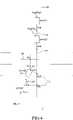
1 ist eine schematische Konfigurationsdarstellung einer Benachrichtigungssteuerungsvorrichtung für ein Fahrzeug gemäß einem ersten Ausführungsbeispiel (Vorrichtung des ersten Ausführungsbeispiels) der vorliegenden Erfindung.1 12 is a schematic configuration diagram of a notification control device for a vehicle according to a first embodiment (device of the first embodiment) of the present invention.2A ist eine Darstellung zur Veranschaulichung eines Beispiels zu dem Zeitpunkt, zu dem eine Bedingung 1-4 erfüllt ist.2A Fig. 12 is a diagram showing an example at the time when a condition 1-4 is satisfied.2B ist eine Darstellung zur Veranschaulichung eines weiteren Beispiels zu dem Zeitpunkt, zu dem die Bedingung 1-4 erfüllt ist.2 B Fig. 12 is a diagram showing another example at the time when the condition 1-4 is satisfied.2C ist eine Darstellung zur Veranschaulichung eines Beispiels, wenn die Bedingung 1-4 nicht erfüllt ist.2C Fig. 14 is a diagram showing an example when condition 1-4 is not satisfied.3 ist eine Darstellung zur Veranschaulichung eines Einstellverfahrens für ein xy-Koordinatensystem.3 Fig. 12 is a diagram showing a setting method for an xy coordinate system.4 ist eine Darstellung zur Veranschaulichung einer Vorbedingung und einer ersten Ausführungsbedingung für die Benachrichtigungssteuerung.4 Fig. 12 is a diagram showing a precondition and a first execution condition for the notification control.5A ist eine Darstellung zur Veranschaulichung einer unnötigen Operation der Benachrichtigungssteuerung.5A Fig. 12 is a diagram showing an unnecessary operation of the notification control.5B ist eine Darstellung zur Veranschaulichung der unnötigen Operation der Benachrichtigungssteuerung.5B Fig. 12 is a diagram showing the unnecessary operation of the notification control.6 ist ein Flussdiagramm zur Veranschaulichung einer Routine, die von einer CPU einer Benachrichtigungssteuerungs-ECU der Vorrichtung des ersten Ausführungsbeispiels ausgeführt wird.6 14 is a flowchart showing a routine executed by a CPU of a notification control ECU of the device of the first embodiment.7 ist eine schematische Konfigurationsdarstellung einer Benachrichtigungssteuerungsvorrichtung für ein Fahrzeug gemäß einem zweiten Ausführungsbeispiel (Vorrichtung des zweiten Ausführungsbeispiels) der vorliegenden Erfindung.7 12 is a schematic configuration diagram of a notification control device for a vehicle according to a second embodiment (device of the second embodiment) of the present invention.8 ist ein Flussdiagramm zur Veranschaulichung einer Routine, die von einer CPU einer Benachrichtigungssteuerungs-ECU der Vorrichtung des zweiten Ausführungsbeispiels ausgeführt wird.8th 9A ist ein Zeitdiagramm zur Darstellung eines Einstellungsverfahrens für eine obere Grenzwertperiode Tu zu dem Zeitpunkt, zu dem die Steuerung der Benachrichtigung über die betreffende Art ausgeführt wird.9A Fig. 12 is a time chart showing a setting procedure for an upper limit value period Tu at the time when the pertinent kind notification control is executed.9B ist ein Zeitdiagramm zur Darstellung eines Einstellverfahrens für die obere Grenzwertperiode Tu zu dem Zeitpunkt, zu dem die Benachrichtigungssteuerung in dem zweiten Ausführungsbeispiel ausgeführt wird.9B
BESCHREIBUNG DER AUSFÜHRUNGSBEISPIELEDESCRIPTION OF THE EXEMPLARY EMBODIMENTS
(Erstes Ausführungsbeispiel)(First embodiment)
(Konfiguration)(Configuration)
Nun wird eine Benachrichtigungssteuerungsvorrichtung für ein Fahrzeug gemäß einem ersten Ausführungsbeispiel (im Folgenden auch als „Vorrichtung des ersten Ausführungsbeispiels“ bezeichnet) der vorliegenden Erfindung unter Bezugnahme auf die Zeichnungen beschrieben. Wie in
Die Benachrichtigungssteuerungs-ECU 10 ist so konfiguriert, dass sie jedes Mal, wenn eine vorbestimmte Zeitspanne bzw. Periode verstreicht, Informationen oder Signale erfasst, die von den Sensoren und Schaltern 11 bis 14 ausgegeben, erfasst oder erzeugt werden, und dass sie die Elemente (Vorrichtungen) 21 und 22 auf der Grundlage der erfassten Signale steuert. Die Benachrichtigungssteuerungs-ECU 10 wird im Folgenden auch einfach als „ECU 10“ bezeichnet.The
Der Kamerasensor 11 (Umgebungsinformationenbezugsvorrichtung) ist an einer Rückfläche eines Raumspiegels (Innenspiegel/Rückspiegel) des eigenen Fahrzeugs V angebracht. Der Kamerasensor 11 erfasst ein Bild einer Landschaft vor dem eigenen Fahrzeug, erfasst (detektiert) 3D-Objekte, die vor dem eigenen Fahrzeug V vorhanden sind, basierend auf den erfassten Bilddaten, und berechnet eine relative Beziehung zwischen dem eigenen Fahrzeug V und jedem der 3D-Objekte. „Die relative Beziehung zwischen dem eigenen Fahrzeug V und dem 3D-Objekt“ umfasst einen Abstand bzw. eine Distanz zwischen dem eigenen Fahrzeug V und dem 3D-Objekt, eine Orientierung und eine relative Geschwindigkeit des 3D-Objekts in Bezug auf das eigene Fahrzeug V und ähnliches. Zu den 3D-Objekten gehören bewegte Objekte (z. B. andere Fahrzeuge und Fußgänger) und stationäre Objekte (z. B. ein Mittelstreifen, Leitplanken und Straßenbäume). Das sich bewegende Objekt ist ein bewegliches 3D-Objekt und bedeutet nicht nur ein sich bewegendes 3D-Objekt.The camera sensor 11 (surrounding information obtaining device) is attached to a rear surface of a room mirror (inside mirror/rearview mirror) of the own vehicle V. FIG. The
Darüber hinaus erfasst (detektiert) der Kamerasensor 11 anhand der Bilddaten Trennlinien, die sich vor dem eigenen Fahrzeug V erstrecken, und berechnet anhand der erkannten Trennlinien die Form jeder Fahrspur (Bereich zwischen zwei nebeneinanderliegenden Trennlinien). Das heißt, die Fahrspur wird durch die Trennlinien definiert. Der Kamerasensor 11 ist in der Lage, zumindest die Formen einer Fahrspur (Fahrspur, auf der sich das eigene Fahrzeug V befindet), einer primären Nachbarspur neben der Fahrspur und einer sekundären Nachbarspur neben der primären Nachbarspur (auf einer der Fahrspur gegenüberliegenden Seite) zu berechnen.In addition, the
Der Kamerasensor 11 gibt die wie vorstehend beschrieben gewonnenen Informationen als „Umgebungsinformationen“ an die ECU 10 aus.The
Der Abbiegesignalschalter 12 (Blinkerschalter) wird in Abhängigkeit von der Stellung eines Abbiegesignalhebels (Bedieneinheit) WL ein- oder ausgeschaltet. Der Abbiegesignalhebel WL ist die Bedieneinheit, die von einem Fahrer zum Betätigen (Blinken) von Abbiegesignalen (Fahrtrichtungsanzeiger) betätigt wird, und ist an einer Lenksäule (nicht dargestellt) angebracht. Der Abbiegesignalhebel WL ist so konfiguriert, dass er um eine Stützwelle in eine rechte Position, die „eine um einen vorbestimmten Winkel θ aus einer neutralen Position nach rechts gedrehte Position“ ist, und eine linke Position, die „eine um den Winkel θ aus der neutralen Position nach links gedrehte Position“ ist, bewegt werden kann.The turn signal switch 12 (turn signal switch) is switched on or off depending on the position of a turn signal lever (operating unit) WL. The turn signal lever WL is the operation unit operated by a driver to operate (blink) turn signals (turn signals), and is attached to a steering column (not shown). The turn signal lever WL is configured to be rotated about a support shaft to a right position that is “a position rotated rightward by a predetermined angle θ from a neutral position” and a left position that is “a position rotated by the angle θ from the neutral position left rotated position” can be moved.
Der Abbiegesignalschalter 12 umfasst einen Rechtsabbiegesignalschalter 12R und einen Linksabbiegesignalschalter 12L. Der Rechtsabbiegesignalschalter 12R wird eingeschaltet (erzeugt ein EIN-Signal), wenn sich der Abbiegesignalhebel WL in der rechten Position befindet, und wird ansonsten ausgeschaltet (erzeugt ein AUS-Signal). Der Linksabbiegesignalschalter 12L wird eingeschaltet (erzeugt ein EIN-Signal), wenn sich der Abbiegesignalhebel WL in der linken Position befindet, und wird ansonsten ausgeschaltet (erzeugt ein AUS-Signal). Die ECU 10 erfasst das vom Abbiegesignalschalter 12 erzeugte Signal und erfasst den Betriebszustand des Abbiegesignalhebels WL anhand des Signals.The
Wenn der Rechtsabbiegesignalschalter 12R oder der Linksabbiegesignalschalter 12L das EIN-Signal erzeugt, wird das EIN-Signal an das Steuergerät (z. B. eine Messinstrumenten-ECU) übertragen, das den Betrieb des Abbiegesignals steuert. Wenn die ECU das EIN-Signal empfängt, betätigt (blinkt) die ECU das entsprechende Rechts- oder Linksabbiegesignal.When the right-
Der Fahrzeuggeschwindigkeitssensor 13 (Fahrzeuggeschwindigkeitserfassungsvorrichtung) erfasst eine Geschwindigkeit „v“ des eigenen Fahrzeugs V (im Folgenden als „Fahrzeuggeschwindigkeit“ bezeichnet) und gibt ein entsprechendes Erfassungssignal an die ECU 10 aus.The vehicle speed sensor 13 (vehicle speed detection device) detects a speed “v” of the host vehicle V (hereinafter referred to as “vehicle speed”) and outputs a corresponding detection signal to the
Der Lenkwinkelsensor 14 (Lenkungseingabewerterfassungsvorrichtung) erfasst einen Lenkwinkel es eines Lenkrads und gibt ein entsprechendes Erfassungssignal an die ECU 10 aus. Der Lenkwinkel es ist eine Art von Eingabewert, der auf der Lenkbetätigung (Betätigung des Lenkrads) durch den Fahrer basiert. Der Lenkwinkelsensor 14 entspricht einem Beispiel für eine „Fahrbetriebszustandserfassungsvorrichtung“.The steering angle sensor 14 (steering input value detecting device) detects a steering angle es of a steering wheel and outputs a corresponding detection signal to the
Die Instrumententafel 21 ist vor einem Fahrersitz (an einer für den Fahrer visuell erfassbaren Position) des eigenen Fahrzeugs V installiert. Der Lautsprecher 22 ist Bestandteil eines Navigationssystems (nicht dargestellt) und wird in der Nähe eines Touchpanel-Displays (nicht dargestellt) installiert. Die Instrumententafel 21 und der Lautsprecher 22 entsprechen Beispielen für eine „Benachrichtigungsvorrichtung“.The
(Details der Operation)(Details of the operation)
Nun werden Details der Operation der ECU 10 beschrieben. Mit einer Konfiguration des Standes der Technik, insbesondere einer Konfiguration, in der bestimmt wird, ob die Ausführung der Benachrichtigungssteuerung erforderlich ist oder nicht, basierend auf vorhergesagten Trajektorien des eigenen Fahrzeugs V und eines entgegenkommenden Fahrzeugs Vop, ist es unmöglich, Formen der vorhergesagten Trajektorien während einer ersten Periode (eine Weile nach einem Start der Rechtsabbiegen) angemessen zu berechnen, und kann folglich die Benachrichtigungssteuerung zu einem Zeitpunkt früher als die autonome Bremssteuerung ausführen. Wenn die Benachrichtigungssteuerung zu einem früheren Zeitpunkt als die autonome Bremssteuerung ausgeführt werden soll, besteht die Gefahr, dass eine unnötige Operation auftritt. Daher ist in dem ersten Ausführungsbeispiel die ECU 10 so konfiguriert, dass sie die Kollisionsmöglichkeit mit dem entgegenkommenden Fahrzeug Vop ohne Verwendung der vorhergesagten Trajektorien bestimmt.Details of the operation of the
Konkret bestimmt die ECU 10 zunächst, ob eine Vorbedingung für die Benachrichtigungssteuerung erfüllt ist oder nicht. Die Vorbedingung ist eine Bedingung, die erfüllt ist, wenn „die Möglichkeit besteht, dass das eigene Fahrzeug V nach rechts abbiegt, während sich das entgegenkommende Fahrzeug Vop nähert“, und die erfüllt ist, wenn sowohl die folgende Bedingung 1 als auch die Bedingung 2 erfüllt sind. Dabei wird eine Richtung, in der sich die Gegenfahrbahn in Bezug auf die Fahrspur befindet, als „spezifische Richtung“ definiert. In dem ersten Ausführungsbeispiel (und dem weiter nachstehend beschriebenen zweiten Ausführungsbeispiel) ist die spezifische Richtung die rechte Richtung.Specifically, the
(Bedingung 1) Das entgegenkommende Fahrzeug Vop nähert sich.(Condition 1) The oncoming vehicle Vop is approaching.
(Bedingung 2) Der Rechtsabbiegesignalschalter 12R ist eingeschaltet.(Condition 2) The right
Zunächst wird die Bedingung 1 beschrieben. Die Bedingung 1 ist erfüllt, wenn ein in den Umgebungsinformationen enthaltenes 3D-Objekt alle der folgenden vier Bedingungen erfüllt.First, the condition 1 will be described. Condition 1 is met when a 3D object included in the environment information satisfies all of the following four conditions.
(Bedingung 1-1) Das 3D-Objekt befindet sich auf der primären Nachbarspur und/oder der sekundären Nachbarspur.(Condition 1-1) The 3D object is on the primary adjacent track and/or the secondary adjacent track.
(Bedingung 1-2) Der Typ des 3D-Objekts ist ein Fahrzeug.(Condition 1-2) The type of the 3D object is a vehicle.
(Bedingung 1-3) Der Betrag der Geschwindigkeit des 3D-Objekts ist gleich oder höher als ein vorgegebener Geschwindigkeitsschwellenwert voth.(Condition 1-3) The magnitude of the speed of the 3D object is equal to or higher than a predetermined speed threshold voth.
(Bedingung 1-4) Es wird vorhergesagt, dass das 3D-Objekt in Zukunft rechts an der gegenwärtigen Position des eigenen Fahrzeugs V vorbeifahren bzw. passieren wird.(Condition 1-4) It is predicted that the 3D object will pass the current position of the own vehicle V on the right in the future.
Die ECU 10 bestimmt, dass die Bedingung 1-1 erfüllt ist, wenn ein 3D-Objekt auf der primären Nachbarspur und/oder der sekundären Nachbarspur, die in den Umgebungsinformationen enthalten sind, vorhanden ist, und bestimmt, dass die Bedingung 1-1 ansonsten nicht erfüllt ist. Wenn die Trennlinien an einer Kreuzung unterbrochen werden, verlängert die ECU 10 die Trennlinien in eine Verlängerungsrichtung davon, um dadurch zu bestimmen, ob die Bedingung 1-1 erfüllt ist oder nicht.The
Die ECU 10 ist so konfiguriert, dass sie in der Lage ist, den Typ des 3D-Objekts durch Verwendung einer bekannten Methode des Mustervergleichs zu identifizieren. Wenn der identifizierte Typ des 3D-Objekts das Fahrzeug ist, bestimmt die ECU 10, dass die Bedingung 1-2 erfüllt ist, und bestimmt, dass die Bedingung 1-2 sonst nicht erfüllt ist.The
Die ECU 10 berechnet die Geschwindigkeit vo des 3D-Objekts aus der relativen Geschwindigkeit des 3D-Objekts, die in den Umgebungsinformationen enthalten ist. Wenn der Betrag der Fahrgeschwindigkeit vo gleich oder größer als der Geschwindigkeitsschwellenwert voth (|vo|≥voth) ist, bestimmt die ECU 10, dass die Bedingung 1-3 erfüllt ist, und bestimmt, dass die Bedingung 1-3 sonst nicht erfüllt ist.The
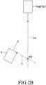
Unter Bezugnahme auf
Die ECU 10 bestimmt, dass die Bedingung 1-4 erfüllt ist, wenn die Verlängerung Lo auf der rechten Seite (spezifische Richtungsseite) der gegenwärtigen Position des eigenen Fahrzeugs V verläuft, und bestimmt, dass die Bedingung 1-4 ansonsten nicht erfüllt ist. Die ECU 10 bestimmt, ob die Verlängerung Lo auf der rechten Seite der gegenwärtigen Position des eigenen Fahrzeugs V verläuft oder nicht, basierend darauf, ob die Verlängerung Lo und eine Verlängerung L (nachstehend beschrieben) einander schneiden oder nicht. Das heißt, die ECU 10 legt als Verlängerung L eine virtuelle Linie fest, die einen rechten vorderen Eckbereich des eigenen Fahrzeugs V als Startpunkt hat und sich in Richtung einer fahrzeugbreiten Außenrichtung erstreckt (d.h. eine Richtung orthogonal zur Bewegungsrichtung (siehe Pfeile) des eigenen Fahrzeugs V und weg vom eigenen Fahrzeug). Danach bestimmt die ECU 10, ob sich die Verlängerung Lo mit der Verlängerung L schneidet oder nicht. Wenn sich die Verlängerung Lo mit der Verlängerung L schneidet, bestimmt die ECU 10, dass die Verlängerung Lo auf der rechten Seite der gegenwärtigen Position des eigenen Fahrzeugs V vorbeifährt, d.h. es wird vorhergesagt, dass das andere Fahrzeug Vo in Zukunft auf der rechten Seite der gegenwärtigen Position des eigenen Fahrzeugs V vorbeifährt (die Bedingung 1-4 ist erfüllt). Indessen, wenn die Verlängerung Lo sich nicht mit der Verlängerung L schneidet, bestimmt die ECU 10, dass die Verlängerung Lo nicht auf der rechten Seite der gegenwärtigen Position des eigenen Fahrzeugs V vorbeifährt bzw. passiert, d.h. es wird nicht vorhergesagt, dass das andere Fahrzeug Vo in der Zukunft auf der rechten Seite der gegenwärtigen Position des eigenen Fahrzeugs V vorbeifährt bzw. passiert (die Bedingung 1-4 ist nicht erfüllt).The
In den Beispielen von
Die Bedingung 2 wird nun beschrieben. Die ECU 10 bestimmt, dass die Bedingung 2 erfüllt ist, wenn der Rechtsabbiegesignalschalter 12R eingeschaltet ist, und bestimmt, dass die Bedingung 2 nicht erfüllt ist, wenn der Rechtsabbiegesignalschalter 12R ausgeschaltet ist. „Wenn der Rechtsabbiegesignalschalter 12R eingeschaltet ist“ kann auch als ein Zustand betrachtet werden, in dem sich der Abbiegesignalhebel WL in dem Betriebszustand befindet, der der Betätigung der Abbiegesignal auf der rechten Seite entspricht. Die Reihenfolge der Bestimmung der Bedingung 1 und der Bedingung 2 ist nicht besonders festgelegt.The condition 2 will now be described. The
Wenn sowohl die Bedingung 1 als auch die Bedingung 2 erfüllt sind und die Vorbedingung entsprechend erfüllt ist (d.h. es besteht die Möglichkeit, dass das eigene Fahrzeug V nach rechts abbiegt, während sich das entgegenkommende Fahrzeug Vop nähert), bestimmt die ECU 10, ob eine erste Ausführungsbedingung für die Benachrichtigungssteuerung erfüllt ist oder nicht. Die erste Ausführungsbedingung ist eine Bedingung, die erfüllt ist, wenn „die Möglichkeit besteht, dass das eigene Fahrzeug mit dem entgegenkommenden Fahrzeug Vop kollidiert, bevor das eigene Fahrzeug das Rechtsabbiegen vollendet“, und die erfüllt ist, wenn sowohl die folgende Bedingung 3 als auch die Bedingung 4 erfüllt sind. „Das Rechtsabbiegen vollenden“ bedeutet, dass, wenn das eigene Fahrzeug V in einer Kreuzung nach rechts abbiegt, ein hinteres Ende des eigenen Fahrzeugs V in „eine kreuzende Fahrspur einfährt, die in der Kreuzung eine Fahrspur kreuzt, auf der das eigene Fahrzeug V vor dem Rechtsabbiegen gefahren ist“, und bedeutet, dass, wenn das eigene Fahrzeug V auf der gegenüberliegenden Fahrspur nach rechts abbiegt, um in einen Parkplatz einer Einrichtung oder dergleichen entlang der gegenüberliegenden Fahrspur einzufahren, das hintere Ende des eigenen Fahrzeugs V in den Parkplatz oder dergleichen fährt.When both the condition 1 and the condition 2 are satisfied and the precondition is correspondingly satisfied (i.e., there is a possibility that the own vehicle V is turning right while the oncoming vehicle Vop is approaching), the
(Bedingung 3) Ein seitliche Bewegungsdistanz dy des eigenen Fahrzeugs V nach Ablauf einer vorbestimmten Referenzperiode Tc ist gleich oder größer als ein vorbestimmter Distanzschwellenwert Dth.(Condition 3) A lateral movement distance dy of the own vehicle V after a lapse of a predetermined reference period Tc is equal to or greater than a predetermined distance threshold value Dth.
(Bedingung 4) Eine Zeitdauer bzw. Periode Tx, die das eigene Fahrzeug V benötigt, um das entgegenkommende Fahrzeug Vop in Längsrichtung virtuell zu passieren, ist gleich oder länger als eine vorbestimmte untere Grenzperiode TI und gleich oder kürzer als eine vorbestimmte obere Grenzperiode Tu (≤Tc)(Condition 4) A period Tx required for the own vehicle V to virtually pass the oncoming vehicle Vop in the longitudinal direction is equal to or longer than a predetermined lower limit period TI and equal to or shorter than a predetermined upper limit period Tu ( ≤Tc)
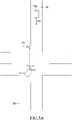
Zunächst wird die Bedingung 3 beschrieben. Wenn die Vorbedingung erfüllt ist, stellt die ECU 10 ein xy-Koordinatensystem ein. Insbesondere setzt die ECU 10, wie in
Danach teilt die ECU 10 eine vom Fahrzeuggeschwindigkeitssensor 13 erfasste Fahrzeuggeschwindigkeit „v“ in eine Längsgeschwindigkeit vx, die eine Komponente in Längsrichtung ist, und eine Quer- bzw. Seitengeschwindigkeit vy, die eine Komponente in Quer- bzw. Seitenrichtung ist, auf. Die ECU 10 verwendet ein bekanntes Verfahren, um eine Bewegungsdistanz „d“ des eigenen Fahrzeugs V in einem Fall zu schätzen, in dem angenommen wird, dass sich das eigene Fahrzeug V vom gegenwärtigen Zeitpunkt für die Bezugsperiode Tc bewegt, und zwar auf der Grundlage der ersten Fahrzeuginformationen einschließlich des vom Lenkwinkelsensor 14 erfassten Lenkwinkels θs, einer Lenkwinkelgeschwindigkeit cos (zeitliche Ableitung des Lenkwinkels θs) und der Quer- bzw. Seitengeschwindigkeit vy. Danach berechnet die ECU 10 als „seitliche Bewegungsdistanz dy“ eine Komponente der Bewegungsdistanz „d“ in seitlicher Richtung. Die Bewegungsdistanz „d“ wird auf der Grundlage des gegenwärtigen Lenkwinkels θs, der gegenwärtigen Lenkwinkelgeschwindigkeit cos und der gegenwärtigen Quer- bzw. Seitengeschwindigkeit vy geschätzt, aber die Konfiguration ist nicht auf dieses Beispiel beschränkt, und es kann eine solche Konfiguration vorgesehen werden, dass die Bewegungsdistanz „d“ beispielsweise auch auf der Grundlage einer Änderungsrate des Lenkwinkels θs, einer Änderungsrate der Lenkwinkelgeschwindigkeit cos und einer Änderungsrate der Quer- bzw. Seitengeschwindigkeit vy über eine vorbestimmte Periode bis zum gegenwärtigen Zeitpunkt geschätzt wird. Darüber hinaus kann die erste Fahrzeuginformation anstelle des Lenkwinkels es und der Lenkwinkelgeschwindigkeit cos oder zusätzlich dazu ein von einem Lenkmomentsensor (nicht dargestellt) erfasstes Lenkdrehmoment enthalten. Die Referenzperiode Tc entspricht einem Beispiel für eine „erste Referenzperiode“.Thereafter, the
Danach bestimmt die ECU 10, ob die seitliche Bewegungsdistanz dy gleich oder größer als der vorbestimmte Distanzschwellenwert Dth ist oder nicht. Die ECU 10 bestimmt, dass die Bedingung 3 erfüllt ist, wenn eine Beziehung von „dy≥Dth“ erfüllt ist, und bestimmt, dass die Bedingung 3 nicht erfüllt ist, wenn eine Beziehung von „dy < Dth“ erfüllt ist. Als Bezugsperiode Tc wird eine durchschnittliche Periode festgelegt, die das eigene Fahrzeug V benötigt, um das Überqueren der Fahrspur abzuschließen, und ein Wert der Bezugsperiode Tc beträgt beispielsweise 4,0 Sekunden. Außerdem wird als Distanzschwellenwert Dth eine durchschnittliche Fahrspurbreite festgelegt, und ein Wert des Distanzschwellenwerts Dth beträgt beispielsweise 3,5 m.Thereafter, the
Das heißt, die Bedingung 3 ist eine Bedingung, die erfüllt ist, wenn die Möglichkeit, dass das eigene Fahrzeug V die Kreuzung (im engeren Sinne eine Kreuzung, in die die Gegenfahrbahn einmündet) oder die Gegenfahrbahn überquert, wenn sich das eigene Fahrzeug V von der gegenwärtigen Position aus für die durchschnittliche Referenzdauer Tc bewegt, die erforderlich ist, um die Überquerung der Fahrbahn abzuschließen, hoch ist. Bei dieser Konfiguration ist die Wahrscheinlichkeit, dass die Bedingung 3 nicht erfüllt wird, wenn das eigene Fahrzeug V die Fahrspur wechselt, extrem hoch. Durch die Einführung der Bedingung 3 ist es also möglich, in geeigneter Weise zu bestimmen, ob ein Grund für das Einschalten des Rechtsabbiegesignals 12R des eigenen Fahrzeugs V ein Rechtsabbiegen oder ein Fahrspurwechsel ist. Die Bedingung 3 entspricht einem Beispiel für eine „Überquerungsbedingung“. „Vollständige Überquerung einer Kreuzung oder einer Gegenfahrbahn“ wird im Folgenden manchmal einfach als „vollständige Überquerung einer Kreuzung“ bezeichnet.That is, the condition 3 is a condition satisfied when the possibility that the own vehicle V crosses the intersection (strictly speaking, an intersection where the oncoming lane merges) or the oncoming lane when the own vehicle V is moving from from the current position for the reference average duration Tc required to complete crossing the lane is high. With this configuration, the possibility that the condition 3 is not satisfied when the own vehicle V changes lanes is extremely high. Thus, by introducing condition 3, it is possible to appropriately determine whether a reason for turning on the
Wie aus der vorstehenden Beschreibung ersichtlich, geht die Bedingung 3 davon aus, dass „die Seitenrichtung” („y”-Richtung) im Wesentlichen parallel zur Richtung der Fahrspurbreite ist (d.h., die Bewegungsrichtung (-x-Richtung) des entgegenkommenden Fahrzeugs Vop ist im Wesentlichen parallel zur Verlängerungsrichtung der Gegenfahrbahn).As apparent from the above description, the condition 3 assumes that “the lateral direction” (“y” direction) is substantially parallel to the lane width direction (i.e., the moving direction (-x direction) of the oncoming vehicle is Vop essentially parallel to the extension direction of the oncoming lane).
Die Bedingung 4 wird nun beschrieben. Die ECU 10 ist so konfiguriert, dass sie feststellt, ob die Bedingung 4 in dem Zustand erfüllt ist, in dem die Bedingung 3 erfüllt ist. Wenn die Bedingung 3 erfüllt ist, berechnet die ECU 10 die Zeitspanne bzw. Periode Tx, bis das eigene Fahrzeug V das entgegenkommende Fahrzeug Vop in Längsrichtung virtuell passiert, wenn angenommen wird, dass „das eigene Fahrzeug V eine gleichmäßige lineare Bewegung mit der Längsgeschwindigkeit vx ausführt und das entgegenkommende Fahrzeug Vop sich unter Beibehaltung des gegenwärtigen Bewegungszustands bewegt.“ „Praktisch in Längsrichtung passieren“ bedeutet, dass sich das eigene Fahrzeug V und das entgegenkommende Fahrzeug Vop in Längsrichtung annähern, ihre „x“-Koordinaten vorübergehend übereinstimmen und sich die Fahrzeuge danach in Längsrichtung voneinander entfernen. Darüber hinaus bedeutet „ein Zeitpunkt, an dem ... in Längsrichtung praktisch passiert wird“, einen Zeitpunkt, an dem die „x“-Koordinate des eigenen Fahrzeugs V und die „x“-Koordinate des entgegenkommenden Fahrzeugs Vop übereinstimmen. Da das eigene Fahrzeug V das entgegenkommende Fahrzeug Vop nicht tatsächlich passiert, wird der Zeitraum bzw. Zeitspanne Tx im Folgenden auch als „virtuelle Passierperiode Tx“ bezeichnet. Die virtuelle Passierperiode Tx kann berechnet werden, indem „eine Komponente in Längsrichtung der Distanz zwischen dem eigenen Fahrzeug V und dem entgegenkommenden Fahrzeug Vop“ durch „eine Summe aus ‚einem Betrag der Längsgeschwindigkeit vx des eigenen Fahrzeugs V‘ und „einem Betrag der Fahrzeuggeschwindigkeit vop des entgegenkommenden Fahrzeugs Vop'” dividiert wird.The condition 4 will now be described. The
Die ECU 10 bestimmt, ob die virtuelle Passierperiode Tx gleich oder länger als die vorbestimmte untere Grenzperiode TI und gleich oder kürzer als die vorbestimmte obere Grenzperiode Tu ist oder nicht, bestimmt, dass die Bedingung 4 erfüllt ist, wenn eine Beziehung „TI≤Tx≤Tu“ erfüllt ist, und bestimmt, dass die Bedingung 4 nicht erfüllt ist, wenn eine Beziehung „Tx<TI“ oder eine Beziehung „Tu<Tx“ erfüllt ist. Wenn eine Position, an der das eigene Fahrzeug V das entgegenkommende Fahrzeug Vop in Längsrichtung virtuell passiert, als „virtueller Passierpunkt Px“ definiert wird, ist der virtuelle Passierpunkt Px von der gegenwärtigen Position des eigenen Fahrzeugs V (d.h. dem Ursprung) um vx-Tx in Richtung +x entfernt. Der virtuelle Passierpunkt Px ist ein Punkt, der weiter entfernt ist, wenn die virtuelle Passierperiode Tx länger wird, und der näher liegt, wenn die virtuelle Passierperiode Tx kürzer wird. Mit anderen Worten: Der virtuelle Passierpunkt Px ist weit entfernt, wenn sich das entgegenkommende Fahrzeug Vop an einer weit entfernten Position bewegt und/oder die Fahrzeuggeschwindigkeit vop relativ niedrig ist (in einem Bereich, der gleich oder höher als der Geschwindigkeitsschwellenwert voth ist). Außerdem wird der virtuelle Passierpunkt Px nahe positioniert, wenn sich das entgegenkommende Fahrzeug Vop in einer nahen Position befindet und/oder die Fahrzeuggeschwindigkeit vop relativ hoch ist.The
Als obere Grenzperiode Tu wird ein vorbestimmter Wert (z. B. 3,2 Sekunden) festgelegt, der gleich oder kürzer als die Referenzperiode Tc ist. Wenn die Bedingung 4 erfüllt ist, weil die Periode Tu die Beziehung „Tu≤Tc“ erfüllt, kann der virtuelle Passierpunkt Px im Schnittpunkt positioniert werden. Dementsprechend kann die obere Grenzperiode Tu als „der maximale Wert der virtuellen Passierperiode Tx, bei dem der virtuelle Passierpunkt Px innerhalb des Schnittpunkts verbleibt“ betrachtet werden. Wenn sich der Abstand bzw. die Distanz zum entgegenkommenden Fahrzeug Vop beim Rechtsabbiegen des eigenen Fahrzeugs V bis zu einem gewissen Grad verringert, kann der Fahrer das entgegenkommende Fahrzeug Vop erfassen, und es wird daher davon ausgegangen, dass der Fahrer freiwillig einen Fahrvorgang (typischerweise einen Bremsvorgang) ausführt (d.h. die Lenkbewegung nach rechts vorübergehend stoppt), um die Kollision mit dem entgegenkommenden Fahrzeug Vop zu vermeiden. Auf der Grundlage dieser Erfassungen wird als unterer Grenzperiode TI „der Mindestwert der virtuellen Passierperiode Tx, in dem der Fahrer aufgrund der hohen Wahrscheinlichkeit, dass er das entgegenkommende Fahrzeug Vop nicht erfassen (visuell erfassen) kann, den Lenkvorgang nach rechts fortsetzen darf“ festgelegt. Der Wert der unteren Grenzperiode TI beträgt beispielsweise 1,0 Sekunden. Die obere Grenzwertdauer Tu und die untere Grenzwertdauer TI können variabel eingestellt werden. Das heißt, die Periode Tu und die Periode TI können jeweils auf unterschiedliche Werte eingestellt werden für den Fall, dass das entgegenkommende Fahrzeug Vop auf der primären Nachbarspur fährt, und für den Fall, dass das entgegenkommende Fahrzeug Vop auf der sekundären Nachbarspur fährt. In diesem Fall können die Referenzperiode Tc und der Distanzschwellenwert Dth ebenfalls in Abhängigkeit von den Änderungen der Periode Tu und der Periode TI geändert werden.A predetermined value (e.g., 3.2 seconds) equal to or shorter than the reference period Tc is set as the upper limit period Tu. When the condition 4 is satisfied, because the period Tu satisfies the relationship "Tu≤Tc", the virtual passing point Px can be positioned at the intersection. Accordingly, the upper limit period Tu can be regarded as "the maximum value of the virtual passing period Tx at which the virtual passing point Px stays within the intersection". When the distance to the oncoming vehicle Vop decreases to a certain extent when the subject vehicle V turns right, the driver can detect the oncoming vehicle Vop, and it is therefore considered that the driver voluntarily performs a driving operation (typically, a braking) (i.e. temporarily stopping the steering movement to the right) in order to avoid the collision with the oncoming vehicle Vop. Based on these detections, the lower limit period TI is defined as "the minimum value of the virtual passing period Tx in which the driver is allowed to continue steering to the right due to the high probability of not being able to detect (visually detect) the oncoming vehicle Vop". The value of the lower limit period TI is 1.0 second, for example. The upper limit duration Tu and the lower limit duration TI can be set variably. That is, the period Tu and the period TI can be set to different values in the case that the oncoming vehicle Vop is traveling in the primary adjacent lane and in the case that the oncoming vehicle Vop is traveling in the secondary adjacent lane, respectively. In this case, the reference period Tc and the distance threshold Dth can also be changed depending on the changes in the period Tu and the period TI.
Das heißt, die Bedingung 4 ist eine Bedingung, die erfüllt ist, wenn die Möglichkeit, dass das eigene Fahrzeug V mit dem entgegenkommenden Fahrzeug Vop in der Kreuzung kollidiert (d.h. vor Abschluss der Kreuzung), wenn das eigene Fahrzeug V nach rechts abbiegt, während es die gegenwärtige Längsgeschwindigkeit vx beibehält, hoch ist.That is, the condition 4 is a condition that is satisfied when there is a possibility that the own vehicle V collides with the oncoming vehicle Vop in the intersection (i.e., before the completion of the intersection) when the own vehicle V turns right while it maintains the current longitudinal velocity vx is high.
Wenn sowohl die Bedingung 3 als auch die Bedingung 4 erfüllt sind und die erste Ausführungsbedingung folglich erfüllt ist (d.h. es besteht die Möglichkeit, dass das eigene Fahrzeug V mit dem entgegenkommenden Fahrzeug Vop kollidiert, bevor die Rechtsabbiegen abgeschlossen ist), führt die ECU 10 die Benachrichtigungssteuerung aus (Steuerung der Benachrichtigung des Fahrers über die Existenz des entgegenkommenden Fahrzeugs). Konkret führt die ECU 10 die folgende Verarbeitung 1 und Verarbeitung 2 als Benachrichtigungssteuerung aus.When both the condition 3 and the condition 4 are satisfied and the first execution condition is thus satisfied (i.e., there is a possibility that the own vehicle V will collide with the oncoming vehicle Vop before the right turn is completed), the
(Verarbeitung 1) Anzeige einer vorbestimmten Markierung (z. B. eine Markierung zur ausdrücklichen Anzeige der Annäherung des entgegenkommenden Fahrzeugs Vop) auf der Instrumententafel 21(Processing 1) Display of a predetermined mark (e.g., a mark for expressively indicating the approach of the oncoming vehicle Vop) on the
(Verarbeitung 2) Veranlassen des Lautsprechers 22, eine vorher festgelegte Nachricht auszugeben (z. B. die Nachricht „Achten Sie auf ein herannahendes Fahrzeug“)(Processing 2) Making the
Die ECU 10 ist so konfiguriert, dass sie bestimmt, ob die Ausführung der Benachrichtigungssteuerung erforderlich ist oder nicht und ob die Ausführung der Kollisionsvermeidungssteuerung parallel erforderlich ist oder nicht. Die autonome Bremssteuerung, die eine Art der Kollisionsvermeidungssteuerung ist, wird ausgeführt, wenn ein TTC für das entgegenkommende Fahrzeug Vop gleich oder kürzer als ein zweiter TTC-Schwellenwert ist, und die untere Grenzperiode TI wird im Voraus auf einen solchen Wert eingestellt, dass der TTC nicht gleich oder kürzer als der zweite TTC-Schwellenwert während einer Periode wird, in der die Beziehung „TI≤Tx“ erfüllt ist. Dadurch wird verhindert, dass die autonome Bremssteuerung während der Ausführung der Benachrichtigungssteuerung ausgeführt wird.The
Unter Bezugnahme auf
Wie in
Somit bestimmt die ECU 10, ob die Bedingung 3 erfüllt ist oder nicht, um zu bestimmen, ob die erste Ausführungsbedingung für die Benachrichtigungssteuerung erfüllt ist oder nicht. Wie vorstehend beschrieben, wird der Lenkvorgang bei t=t1 nicht ausgeführt, und daher sind der Lenkwinkel es und die Lenkwinkelgeschwindigkeit cos beide im Wesentlichen null. Außerdem bewegt sich das eigene Fahrzeug V in Richtung +x, so dass die Fahrzeuggeschwindigkeit „v“ gleich der Längsgeschwindigkeit vx ist und die Quer- bzw. Seitengeschwindigkeit vy gleich Null (v=vx und vy=0). Dementsprechend ist die seitliche Bewegungsdistanz dy bei t=t1 gleich Null, die Beziehung „dy< Dth“ ist erfüllt, und daher bestimmt die ECU 10, dass die Bedingung 3 bei t=t1 nicht erfüllt ist.Thus, the
Indessen wird bei t=t2 der Lenkvorgang nach rechts ausgeführt, und das eigene Fahrzeug V bewegt sich folglich diagonal nach rechts. Wenn die seitliche Bewegungsdistanz dy, der auf der Grundlage des Lenkwinkels θs, der Lenkwinkelgeschwindigkeit cos und der seitlichen Geschwindigkeit vy berechnet wird, die Beziehung „dy≥Dth“ bei t=t2 erfüllt, stellt die ECU 10 fest, dass die Bedingung 3 bei t=t2 erfüllt ist (d.h. die Wahrscheinlichkeit, dass das eigene Fahrzeug V die Kreuzung (Kreuzung, in die die Gegenfahrspur 32 einmündet) überquert, wenn sich das eigene Fahrzeug V von der gegenwärtigen Position aus für die Referenzperiode Tc bewegt, ist hoch).Meanwhile, at t=t2, the steering operation is performed to the right, and consequently the own vehicle V moves diagonally to the right. When the lateral movement distance dy calculated based on the steering angle θs, the steering angular velocity cos, and the lateral velocity vy satisfies the relationship “dy≥Dth” at t=t2, the
Danach berechnet die ECU 10 die virtuelle Passierperiode Tx, um festzustellen, ob die Bedingung 4 bei t=t2 erfüllt ist oder nicht. In diesem Beispiel passieren sich das eigene Fahrzeug V und das entgegenkommende Fahrzeug Vop virtuell in Längsrichtung auf einer Linie Lp, die parallel zur „y“-Achse verläuft. Der virtuelle Passierpunkt Px befindet sich also an einem Schnittpunkt zwischen der „x“-Achse (siehe gestrichelte Linie) und der Linie Lp. Wenn die ECU 10 die virtuelle Passierperiode Tx berechnet, bestimmt die ECU 10, ob die Beziehung „TI≤Tx≤Tu“ erfüllt ist oder nicht. Wenn beispielsweise die virtuelle Passierperiode Tx bei t=t2 2,0 Sekunden beträgt, ist die Beziehung „TI≤Tx≤Tu“ erfüllt, und daher bestimmt die ECU 10, dass die Bedingung 4 bei t=t2 erfüllt ist (d.h. die Wahrscheinlichkeit, dass das eigene Fahrzeug V mit dem entgegenkommenden Fahrzeug Vop in der Kreuzung kollidiert, wenn das eigene Fahrzeug V nach rechts abbiegt, während es die gegenwärtige Längsgeschwindigkeit vx beibehält, ist hoch). Folglich bestimmt die ECU 10, dass die erste Ausführungsbedingung für die Benachrichtigungssteuerung bei t=t2 erfüllt ist, und führt die Benachrichtigungssteuerung aus. In
Als Ergebnis der Ausführung der Benachrichtigungssteuerung kann der Fahrer das Vorhandensein des entgegenkommenden Fahrzeugs Vop zu einem früheren Zeitpunkt als die autonome Bremssteuerung erfassen und kann daher den Fahrbetrieb zur Vermeidung der Kollision mit dem entgegenkommenden Fahrzeug Vop ausführen, mit dem Ergebnis, dass eine Häufigkeit der Ausführung der autonomen Bremssteuerung reduziert werden kann. Darüber hinaus kann durch Einstellen der oberen Grenzperiode Tu auf den vorbestimmten Wert, der gleich oder kürzer als die Referenzperiode Tc ist („der maximale Wert der Periode Tx für den virtuellen Passierpunkt Px, um innerhalb der Kreuzung zu bleiben“), und durch Einstellen der unteren Grenzperiode TI auf „den minimalen Wert der Periode Tx, in der der Fahrer den Lenkvorgang nach rechts fortsetzen kann, aufgrund der hohen Wahrscheinlichkeit, dass der Fahrer das entgegenkommende Fahrzeug Vop nicht erfassen kann“, der unnötige Betrieb der Benachrichtigungssteuerung unterdrückt werden.As a result of executing the notification control, the driver can detect the presence of the oncoming vehicle Vop at an earlier timing than the autonomous braking control and can therefore execute the driving operation for avoiding the collision with the oncoming vehicle Vop, with the result that a frequency of execution of the autonomous brake control can be reduced. In addition, by setting the upper limit period Tu to the predetermined value that is equal to or shorter than the reference period Tc (“the maximum value of the period Tx for the virtual passing point Px to stay inside the intersection”), and by setting the lower limit period TI to "the minimum value of the period Tx in which the driver can continue the steering operation to the right due to the high possibility that the driver cannot detect the oncoming vehicle Vop", the unnecessary operation of the notification control can be suppressed.
Unter Bezugnahme auf
Wenn der Fahrer die Kollisionsvermeidungsoperation nicht freiwillig ausführt, selbst nachdem die Periode Tx kürzer als die untere Grenzperiode TI geworden ist, sinkt die TTC für das entgegenkommende Fahrzeug Vop anschließend auf einen Wert, der gleich oder kürzer als der zweite TTC-Schwellenwert ist, und daher wird die autonome Bremssteuerung ausgeführt, mit dem Ergebnis, dass die Kollision mit dem entgegenkommenden Fahrzeug Vop in geeigneter Weise vermieden werden kann. Das heißt, die Benachrichtigungssteuerung hat den Zweck, den Fahrer über das Vorhandensein des entgegenkommenden Fahrzeugs Vop zu benachrichtigen, wenn eine hohe Wahrscheinlichkeit besteht, dass der Fahrer das entgegenkommende Fahrzeug Vop nicht erfassen kann, selbst in dem Fall, in dem die Möglichkeit besteht, dass das eigene Fahrzeug V mit dem entgegenkommenden Fahrzeug Vop vor der Vollendung der Rechtsabbiegen kollidiert, und hat nicht den Zweck, eine Benachrichtigung über das Vorhandensein des entgegenkommenden Fahrzeugs Vop bereitzustellen, selbst in dem Fall, in dem das entgegenkommende Fahrzeug Vop so nahe ist, dass der Fahrer das entgegenkommende Fahrzeug Vop erfassen kann.If the driver does not voluntarily perform the collision avoidance operation even after the period Tx has become shorter than the lower limit period TI, the TTC for the oncoming vehicle Vop subsequently decreases to a value equal to or shorter than the second TTC threshold value and hence the autonomous braking control is executed, with the result that the collision with the oncoming vehicle Vop can be appropriately avoided. That is, the purpose of the notification control is to notify the driver of the presence of the oncoming vehicle Vop when there is a high possibility that the driver cannot detect the oncoming vehicle Vop even in the case where there is a possibility that own vehicle v collides with the oncoming vehicle Vop before the completion of the right turn, and is not intended to provide notification of the presence of the oncoming vehicle Vop even in the case where the oncoming vehicle Vop is so close that the driver recognizes the oncoming vehicle Vop can capture.
(Spezifische Operation)(Specific operation)
Eine spezifische Operation der ECU 10 wird nun beschrieben. Die CPU der ECU 10 ist so konfiguriert, dass sie jedes Mal, wenn eine vorbestimmte Berechnungsperiode während einer Periode abläuft, in der sich ein Zündschalter in einer EIN-Position befindet, wiederholt eine Routine ausführt, die in einem Flussdiagramm in
Die CPU beginnt die Verarbeitung ab Schritt 600 von
In Schritt 620 bestimmt die CPU, ob der Rechtsabbiegesignalschalter 12R eingeschaltet ist oder nicht (Bedingung 2). Wenn der Rechtsabbiegesignalschalter 12R ausgeschaltet ist, stellt die CPU in Schritt 620 „Nein“ fest (d.h., sie stellt fest, dass die Bedingung 2 nicht erfüllt ist (die Vorbedingung ist nicht erfüllt)), und der Prozess fährt mit Schritt 695 fort. Dann beendet die CPU vorübergehend die Routine. Indessen, wenn der Rechtsabbiegesignalschalter 12R eingeschaltet ist, macht die CPU eine Bestimmung von „Ja“ in Schritt 620 (das heißt, bestimmt, dass die Bedingung 2 erfüllt ist (die Vorbedingung ist erfüllt)), und der Prozess geht zu Schritt 630.In
In Schritt 630 bestimmt die CPU, ob die seitliche Bewegungsdistanz dy des eigenen Fahrzeugs V nach dem Ablauf der Referenzperiode Tc gleich oder größer als der Distanzschwellenwert Dth ist (Bedingung 3). Wenn die Beziehung „dy< Dth“ erfüllt ist, trifft die CPU in Schritt 630 die Feststellung „Nein“ (d.h. sie stellt fest, dass die Bedingung 3 nicht erfüllt ist (die erste Ausführungsbedingung ist nicht erfüllt)), und der Prozess fährt mit Schritt 695 fort. Dann beendet die CPU vorübergehend die Routine. Wenn in der Zwischenzeit die Beziehung „dy≥Dth“ erfüllt ist, stellt die CPU in Schritt 630 „Ja“ fest (d.h. sie stellt fest, dass die Bedingung 3 erfüllt ist), und der Prozess geht zu Schritt 640 über.In
In Schritt 640 bestimmt die CPU, ob die virtuelle Passierperiode Tx die Beziehung „TI≤Tx≤Tu“ (Tu≤Tc) erfüllt oder nicht (Bedingung 4). Wenn die Beziehung „Tx< TI“ oder die Beziehung „Tu< Tx“ erfüllt ist, stellt die CPU in Schritt 640 „Nein“ fest (d.h. sie stellt fest, dass die Bedingung 4 nicht erfüllt ist (die erste Ausführungsbedingung ist nicht erfüllt)), und der Prozess geht weiter zu Schritt 695. Dann beendet die CPU vorübergehend die Routine. Wenn in der Zwischenzeit die Beziehung „TI≤Tx≤Tu“ erfüllt ist, stellt die CPU in Schritt 640 „Ja“ fest (d.h. sie stellt fest, dass die Bedingung 4 erfüllt ist (die erste Ausführungsbedingung ist erfüllt)), und der Prozess fährt mit Schritt 650 fort.In
In Schritt 650 steuert die CPU die Instrumententafel 21, um die vorbestimmte Markierung anzuzeigen, und steuert den Lautsprecher 22, um zu bewirken, dass der Lautsprecher 22 die vorbestimmte Nachricht ausspricht. Infolgedessen wird die Benachrichtigungssteuerung ausgeführt. Danach geht der Prozess zu Schritt 695 über, und die CPU beendet vorübergehend die Routine.In
Wie vorstehend beschrieben, ist es gemäß der Vorrichtung des ersten Ausführungsbeispiels möglich, gleichzeitig die Ausführung der Benachrichtigungssteuerung zu einem früheren Zeitpunkt als die autonome Bremssteuerung und die Unterdrückung des unnötigen Betriebs der Benachrichtigungssteuerung während der Rechtsabbiegen zu erreichen.As described above, according to the device of the first embodiment, it is possible to simultaneously achieve the execution of the notification control earlier than the autonomous braking control and the suppression of the unnecessary operation of the notification control during right turns.
(Zweites Ausführungsbeispiel)(Second embodiment)
Nachfolgend wird eine Benachrichtigungssteuerungsvorrichtung für ein Fahrzeug gemäß dem zweiten Ausführungsbeispiel (im Folgenden auch als „Vorrichtung des zweiten Ausführungsbeispiels“ bezeichnet) der vorliegenden Erfindung unter Bezugnahme auf die Zeichnungen beschrieben. Die gleichen Komponenten wie bei dem ersten Ausführungsbeispiel sind mit den gleichen Bezugszeichen versehen. Die Vorrichtung des zweiten Ausführungsbeispiels unterscheidet sich von der Vorrichtung des ersten Ausführungsbeispiels durch das Verfahren zur Bestimmung, „ob die Möglichkeit bzw. Wahrscheinlichkeit, dass das eigene Fahrzeug V die Kreuzung nach Ablauf der Referenzperiode überquert, hoch ist oder nicht.“ Der Unterschied zu der Vorrichtung des ersten Ausführungsbeispiels wird nun im Einzelnen beschrieben.Hereinafter, a notification control device for a vehicle according to the second embodiment (hereinafter also referred to as “the device of the second embodiment”) of the present invention will be described with reference to the drawings. The same components as in the first embodiment are given the same reference numerals. The device of the second embodiment differs from the device of the first embodiment in the method of determining "whether or not the possibility that the own vehicle V crosses the intersection after the lapse of the reference period is high." device The device of the first embodiment will now be described in detail.
(Konfiguration)(Configuration)
Wie in
(Details der Operation)(Details of the operation)
Auch in dem zweiten Ausführungsbeispiel ist die ECU 110 so konfiguriert, dass sie die Kollisionsmöglichkeit mit einem entgegenkommenden Fahrzeug Vop ohne Verwendung der vorhergesagten Trajektorien bestimmt. Insbesondere, wenn sowohl die in dem ersten Ausführungsbeispiel beschriebene Bedingung 1 als auch die Bedingung 2 erfüllt sind und die Vorbedingung folglich erfüllt ist, bestimmt die ECU 110, ob eine zweite Ausführungsbedingung für die Benachrichtigungssteuerung erfüllt ist oder nicht. Die zweite Ausführungsbedingung ist eine Bedingung, die erfüllt ist, wenn „die Möglichkeit besteht, dass das eigene Fahrzeug mit dem entgegenkommenden Fahrzeug Vop kollidiert, bevor das eigene Fahrzeug die Rechtsabbiegen vollendet“, und die erfüllt ist, wenn alle der folgenden Bedingungen 5 bis 7 erfüllt sind.Also in the second embodiment, the
(Bedingung 5) Die Fahrzeuggeschwindigkeit „v“ ist gleich oder höher als ein vorbestimmter Fahrzeuggeschwindigkeitsschwellenwert vth.(Condition 5) The vehicle speed “v” is equal to or higher than a predetermined vehicle speed threshold value vth.
(Bedingung 6) Eine zum Stoppen erforderliche Periode T des eigenen Fahrzeugs V überschreitet eine Bezugszeit Ts.(Condition 6) A period T required for stopping of the own vehicle V exceeds a reference time Ts.
(Bedingung 7) Die virtuelle Durchgangszeit Tx ist gleich oder länger als die untere Grenzperiode TI und gleich oder kürzer als die obere Grenzperiode Tu (≤Ts).(Condition 7) The virtual transit time Tx is equal to or longer than the lower limit period TI and equal to or shorter than the upper limit period Tu (≦Ts).
Zunächst wird die Bedingung 5 beschrieben. Wenn die Vorbedingung erfüllt ist, stellt die ECU 110 das xy-Koordinatensystem ein. Danach stellt die ECU 110 fest, ob die Fahrzeuggeschwindigkeit „v“ gleich oder höher als der Fahrzeuggeschwindigkeitsschwellenwert vth ist oder nicht. Die ECU 110 bestimmt, dass die Bedingung 5 erfüllt ist, wenn die Beziehung „v≥vth“ erfüllt ist, und bestimmt, dass die Bedingung 5 nicht erfüllt ist, wenn die Beziehung „v< vth“ erfüllt ist. Als Schwellenwert für die Fahrzeuggeschwindigkeit vth wird „der Mindestwert der Fahrzeuggeschwindigkeit ‚v‘, bei dem das eigene Fahrzeug V, das mit dem Rechtsabbiegen begonnen hat, die Kreuzung ohne Anhalten in einer Kreuzung oder auf einer Gegenfahrbahn durchfährt“ festgelegt, und der Wert des Schwellenwerts für die Fahrzeuggeschwindigkeit vth beträgt z. B. 15 km pro Stunde. Das heißt, die Bedingung 5 ist eine Bedingung, die erfüllt ist, wenn die Möglichkeit, dass das eigene Fahrzeug V in einer Kreuzung oder auf einer Gegenfahrbahn anhält, gering ist. Die Bedingung 5 entspricht einem Beispiel für „die Überquerungsbedingung“.First, the condition 5 will be described. When the precondition is satisfied, the
Die Bedingung 6 wird nun beschrieben. Die ECU 110 ist so konfiguriert, dass sie feststellt, ob die Bedingung 6 in dem Zustand erfüllt ist, in dem die Bedingung 5 erfüllt ist. Wenn die Bedingung 5 erfüllt ist, verwendet die ECU 110 ein bekanntes Verfahren, um die für das Anhalten des eigenen Fahrzeugs V zum Stoppen erforderliche Periode T zu schätzen, basierend auf zweiten Fahrzeuginformationen, einschließlich des Vorhandenseins oder Nichtvorhandenseins der Betätigung des Bremspedals (Vorhandensein oder Nichtvorhandensein der Bremsbetätigung), die vom Bremsschalter 114 erfasst werden, einer Verzögerung (nachstehend beschrieben) und der Fahrzeuggeschwindigkeit „v“. Die Verzögerung ist eine negative Beschleunigung und kann auf der Grundlage des Übergangs der Fahrzeuggeschwindigkeit „v“ berechnet werden. Die zweite Fahrzeuginformation kann anstelle von oder zusätzlich zu dem Vorhandensein oder Nichtvorhandensein der Betätigung des Bremspedals das Vorhandensein oder Nichtvorhandensein der Bremsbetätigung umfassen, die von einer anderen Vorrichtung erfasst wird, die in der Lage ist, die Bremsbetätigung durch den Fahrer zu erfassen.The condition 6 will now be described. The
Die ECU 110 bestimmt, ob die zum Stoppen erforderliche Periode T die Referenzperiode Ts überschreitet oder nicht, bestimmt, dass die Bedingung 6 erfüllt ist, wenn eine Beziehung „T>ts“ erfüllt ist, und bestimmt, dass die Bedingung 6 nicht erfüllt ist, wenn eine Beziehung „T≤Ts“ erfüllt ist. Die Bezugszeit Ts wird auf der Grundlage einer allgemeinen Periode bzw. Zeitspanne festgelegt, die der Fahrer während des Rechtsabbiegens benötigt, um das Vorhandensein eines entgegenkommenden Fahrzeugs Vop zu bemerken und zu versuchen, das eigene Fahrzeug V anzuhalten, und der Wert der Bezugszeit Ts beträgt beispielsweise 4,0 Sekunden. Das heißt, die Bedingung 6 ist auch dann erfüllt, wenn die Wahrscheinlichkeit, dass der Fahrer das entgegenkommende Fahrzeug Vop nicht erfasst, hoch ist. Die Bedingung 6 entspricht einem Beispiel für die „Überquerungsbedingung“, und der Bezugsperiode Ts entspricht einem Beispiel für einen „zweiten Bezugsperiode“.The
Die Bedingung 7 wird nun beschrieben. Das Steuergerät 110 ist so konfiguriert, dass es feststellt, ob die Bedingung 7 in dem Zustand, in dem die Bedingung 6 erfüllt ist, erfüllt ist oder nicht. Die Bedingung 7 ist die gleiche Bedingung wie die Bedingung 4 in dem ersten Ausführungsbeispiel. Das heißt, wenn die Bedingung 6 erfüllt ist, berechnet die ECU 110 die virtuelle Durchgangsperiode Tx und bestimmt, ob die Periode Tx gleich oder länger als die untere Grenzperiode TI und gleich oder kürzer als die obere Grenzperiode Tu ist oder nicht. Die ECU 110 bestimmt, dass die Bedingung 7 erfüllt ist, wenn die Beziehung „TI≤Tx≤Tu“ erfüllt ist, und bestimmt, dass die Bedingung 7 nicht erfüllt ist, wenn die Beziehung „Tx< TI“ oder die Beziehung „Tu< tx“ erfüllt ist. Für die Periode Tu und die Periode TI werden Werte festgelegt, die auf Gründen beruhen, die denen des ersten Ausführungsbeispiels entsprechen, z.B. Tu=3,2 Sekunden und TI=1,0 Sekunde. Das heißt, die Bedingung 7 ist die Bedingung, die erfüllt ist, wenn die Möglichkeit, dass das eigene Fahrzeug V mit dem entgegenkommenden Fahrzeug Vop in einer Kreuzung kollidiert (d.h. vor dem Abschluss der Kreuzung), wenn das eigene Fahrzeug V nach rechts abbiegt, während es die gegenwärtige Längsgeschwindigkeit vx beibehält, hoch ist. Der Bezugsperiode Ts wird auf einen Wert gesetzt, der die Beziehung „Tu≤Ts“ erfüllt.The condition 7 will now be described. The
Wenn alle Bedingungen 5 bis 7 erfüllt sind und die zweite Ausführungsbedingung folglich erfüllt ist (d.h. es besteht die Möglichkeit, dass das eigene Fahrzeug mit dem entgegenkommenden Fahrzeug Vop kollidiert, bevor das eigene Fahrzeug die Rechtsabbiegen vollendet), führt die ECU 110 die Benachrichtigungssteuerung (Verarbeitung 1 und Verarbeitung 2) aus.When all of the conditions 5 to 7 are satisfied and the second execution condition is thus satisfied (i.e., there is a possibility that the own vehicle will collide with the oncoming vehicle Vop before the own vehicle completes the right turns), the
Bei dieser Konfiguration wird die Benachrichtigungssteuerung nicht ausgeführt, wenn die Bedingung 5 nicht erfüllt ist, d.h. die Beziehung „v< vth“ erfüllt ist. Wenn die Beziehung „v< vth“ in dem Zustand erfüllt ist, in dem die Vorbedingung erfüllt ist, ist die Wahrscheinlichkeit hoch, dass der Fahrer das entgegenkommende Fahrzeug Vop erfasst, um dadurch das eigene Fahrzeug V abzubremsen. Wenn also, wie vorstehend beschrieben, die Möglichkeit, dass der Fahrer das entgegenkommende Fahrzeug Vop erfassen kann, hoch ist, wird die Benachrichtigungssteuerung nicht ausgeführt, wodurch der unnötige Betrieb unterdrückt werden kann.With this configuration, the notification control is not executed if condition 5 is not met, i.e. the relationship "v<vth" is met. When the relationship “v<vth” is satisfied in the state where the precondition is satisfied, the driver has a high possibility of detecting the oncoming vehicle Vop to thereby decelerate the own vehicle V. Therefore, as described above, when the possibility that the driver can detect the oncoming vehicle Vop is high, the notification control is not executed, whereby the unnecessary operation can be suppressed.
Wenn die Bedingung 6 nicht erfüllt ist, d.h. die Beziehung „T≤Ts“ erfüllt ist, wird die Benachrichtigungssteuerung nicht ausgeführt. Wenn die Beziehung „T≤Ts“ erfüllt ist, obwohl die Beziehung „v≥vth“ in dem Zustand, in dem die Vorbedingung erfüllt ist, erfüllt ist, ist die Wahrscheinlichkeit hoch, dass der Fahrer das entgegenkommende Fahrzeug Vop im Verlauf der Rechtsabbiegen bemerkt und versucht hat, das eigene Fahrzeug V anzuhalten. Wenn also, wie vorstehend beschrieben, die Wahrscheinlichkeit, dass der Fahrer das entgegenkommende Fahrzeug Vop erfassen kann, hoch ist, wird die Benachrichtigungssteuerung nicht ausgeführt, wodurch der unnötige Vorgang unterdrückt werden kann.If the condition 6 is not satisfied, i.e. the relationship "T≤Ts" is satisfied, the notification control is not executed. When the relation “T≦Ts” is satisfied, although the relation “v≧vth” is satisfied in the state where the precondition is satisfied, the driver has a high possibility of noticing the oncoming vehicle Vop in the course of right turns and tried to stop the own vehicle V. Therefore, as described above, when the possibility that the driver can detect the oncoming vehicle Vop is high, the notification control is not executed, whereby the unnecessary process can be suppressed.
(Spezifische Operation)(Specific Operation)
Es wird nun eine spezifische Operation der ECU 110 beschrieben. Die CPU der ECU 110 ist so konfiguriert, dass sie wiederholt eine Routine ausführt, die als Flussdiagramm in
Schritt 830: Die CPU stellt fest, ob die Fahrzeuggeschwindigkeit „v“ gleich oder höher als der Fahrzeuggeschwindigkeitsschwellenwert vth ist (Bedingung 5) oder nicht. Wenn die Beziehung „v< vth“ erfüllt ist, stellt die CPU in Schritt 830 „Nein“ fest (d.h. sie stellt fest, dass die Bedingung 5 nicht erfüllt ist (die zweite Ausführungsbedingung ist nicht erfüllt)), und der Prozess fährt mit Schritt 895 fort. Dann beendet die CPU vorübergehend die Routine. Wenn in der Zwischenzeit die Beziehung „v≥vth“ erfüllt ist, stellt die CPU in Schritt 830 „Ja“ fest (d.h. sie stellt fest, dass die Bedingung 5 erfüllt ist), und der Prozess fährt mit Schritt 840 fort.Step 830: The CPU determines whether or not the vehicle speed "v" is equal to or higher than the vehicle speed threshold value vth (Condition 5). If the relationship "v<vth" is satisfied, the CPU determines "No" in step 830 (i.e., it determines that the condition 5 is not satisfied (the second execution condition is not satisfied)), and the process goes to step 895 continued. Then the CPU temporarily ends the routine. In the meantime, if the relationship "v≥vth" is satisfied, the CPU determines "Yes" in step 830 (i.e., it determines that condition 5 is satisfied), and the process proceeds to step 840.
Schritt 840: Die CPU bestimmt, ob die zum Stoppen erforderliche Periode T die Referenzperiode Ts überschreitet oder nicht (Bedingung 6). Wenn die Beziehung „T≤Ts“ erfüllt ist, stellt die CPU in Schritt 840 „Nein“ fest (d.h., sie stellt fest, dass die Bedingung 6 nicht erfüllt ist (die zweite Ausführungsbedingung ist nicht erfüllt)), und der Prozess geht weiter zu Schritt 895. Dann beendet die CPU vorübergehend die Routine. Indessen, wenn die Beziehung „T> Ts“ erfüllt ist, trifft die CPU in Schritt 840 die Feststellung „Ja“ (d.h. sie stellt fest, dass die Bedingung 6 erfüllt ist), und der Prozess fährt mit Schritt 850 fort.Step 840: The CPU determines whether or not the period T required for stopping exceeds the reference period Ts (Condition 6). When the relationship "T≤Ts" is satisfied, the CPU determines "No" (i.e., determines that the condition 6 is not satisfied (the second execution condition is not satisfied)) in
Schritt 850: Die CPU bestimmt, ob die virtuelle Passierperiode Tx die Beziehung „TI≤Tx≤Tu“ (Tu≤Ts) erfüllt oder nicht (Bedingung 7). Wenn die Beziehung „Tx<TI“ oder die Beziehung „Tu<Tx“ erfüllt ist, stellt die CPU in Schritt 850 „Nein“ fest (d.h. sie stellt fest, dass die Bedingung 7 nicht erfüllt ist (die zweite Ausführungsbedingung ist nicht erfüllt)), und der Prozess geht weiter zu Schritt 895. Dann beendet die CPU vorübergehend die Routine. Wenn in der Zwischenzeit die Beziehung „TI≤Tx≤Tu“ erfüllt ist, stellt die CPU in Schritt 850 „Ja“ fest (d.h. sie stellt fest, dass die Bedingung 7 erfüllt ist (die zweite Ausführungsbedingung ist erfüllt)), und der Prozess fährt mit Schritt 650 fort.Step 850: The CPU determines whether the virtual passing period Tx satisfies the relationship "TI≤Tx≤Tu" (Tu≤Ts) met or not (Condition 7). If the relationship "Tx<TI" or the relationship "Tu<Tx" is satisfied, the CPU determines "No" in step 850 (i.e., it determines that condition 7 is not satisfied (the second execution condition is not satisfied) ), and the process proceeds to step 895. Then, the CPU temporarily ends the routine. In the meantime, if the relation “TI≦Tx≦Tu” is satisfied, the CPU determines “Yes” (ie, determines that the condition 7 is satisfied (the second execution condition is satisfied)) in
Wie vorstehend beschrieben, kann die Vorrichtung des zweiten Ausführungsbeispiels Aktionen und Effekte bereitstellen, die denen der Vorrichtung des ersten Ausführungsbeispiels entsprechen.
Wie in
Im Stand der Technik ist, wie in
Im Gegensatz dazu verringert sich bei dem zweiten Ausführungsbeispiel, wie in
In den vorstehenden Ausführungen wurde die Benachrichtigungssteuerungsvorrichtung für ein Fahrzeug gemäß den Ausführungsbeispielen beschrieben, aber die vorliegende Erfindung ist nicht auf die vorstehend genannten Ausführungsbeispiele beschränkt, und verschiedene Änderungen sind innerhalb des Bereichs möglich, die nicht vom Ziel der vorliegenden Erfindung abweichen.In the foregoing, the notification control device for a vehicle according to the embodiments has been described, but the present invention is not limited to the above embodiments, and various changes are possible within the range that does not depart from the gist of the present invention.
Zum Beispiel wird in den vorstehend genannten Ausführungsbeispielen der Fall beschrieben, in dem die spezifische Richtung die rechte Richtung ist, aber die Konfiguration ist nicht auf dieses Beispiel beschränkt. Die vorliegende Erfindung kann auch auf einen Fall angewendet werden, in dem die spezifische Richtung die linke Richtung ist, und eine Konfiguration in diesem Fall kann beschrieben werden, indem „rechts“ in den vorstehend genannten Ausführungsbeispielen als „links“ gelesen wird und „links“ in den vorstehend genannten Ausführungsbeispielen als „rechts“ gelesen wird. Darüber hinaus kann die vorliegende Erfindung auch auf ein Fahrzeug angewendet werden, das durch autonomes Fahren (autonome Fahrsteuerung) fährt.For example, in the above embodiments, the case where the specific direction is the right direction is described, but the configuration is not limited to this example. The present invention can also be applied to a case where the specific direction is the left direction, and a configuration in this case can be described by reading "right" as "left" in the above embodiments and "left" in the above embodiments read as "right". In addition, the present invention can also be applied to a vehicle that runs by autonomous driving (autonomous driving control).
Um während eines Abbiegevorgangs gleichzeitig eine Ausführung einer Benachrichtigungssteuerung zu einem früheren Zeitpunkt als die automatische Bremssteuerung und die Unterdrückung einer unnötigen Betätigung der Benachrichtigungssteuerung zu erreichen, ist eine Benachrichtigungssteuerungsvorrichtung für ein Fahrzeug vorgesehen, die konfiguriert ist, um auf der Grundlage von Umgebungsinformationen und eines Betriebszustands einer Betätigungseinheit zu bestimmen, ob die Möglichkeit besteht, dass ein eigenes Fahrzeug in eine spezifische Richtung abbiegt, während sich ein entgegenkommendes Fahrzeug nähert, um bei einer zustimmenden Bestimmung auf der Grundlage von Fahrzeuginformationen, die einen Lenkeingabewert und/oder das Vorhandensein/Fehlen einer Bremsbetätigung sowie eine Fahrzeuggeschwindigkeit umfassen, zu bestimmen, ob die Möglichkeit, dass das eigene Fahrzeug das Überqueren einer Gegenfahrbahn oder einer Kreuzung nach Ablauf einer Referenzperiode abschließt, hoch ist, und, bei einer zustimmenden Bestimmung, die Benachrichtigungssteuerung auszuführen, wenn eine virtuelle Passierperiode, die erforderlich ist, damit das eigene Fahrzeug das entgegenkommende Fahrzeug virtuell passieren kann, eine untere Grenzperiode oder länger und eine obere Grenzperiode oder kürzer ist, wobei die obere Grenzperiode die Referenzperiode oder kürzer ist, unter der Annahme, dass sich das eigene Fahrzeug in einer Längsrichtung bewegt, die eine entgegengesetzte Richtung einer Bewegungsrichtung des entgegenkommenden Fahrzeugs ist, mit einer Längsgeschwindigkeit, die eine Komponente der Fahrzeuggeschwindigkeit in der Längsrichtung ist, und sich das entgegenkommende Fahrzeug bewegt, während es einen gegenwärtigen Bewegungszustand beibehält.In order to simultaneously achieve execution of notification control at an earlier timing than the automatic brake control and suppression of unnecessary operation of the notification control during a turning operation, a notification control device for a vehicle is provided that is configured to, based on surrounding information and an operating state of a Operation unit to determine whether there is a possibility that an own vehicle turns in a specific direction while an oncoming vehicle is approaching in order to with an affirmative determination based on vehicle information, a steering input value and / or the presence / absence of a brake operation as well include a vehicle speed, determining whether the possibility that the own vehicle completes crossing an oncoming lane or an intersection after the lapse of a reference period is high, and, at ei an affirmative determination to execute the notification control when a virtual passing period required for the own vehicle to virtually pass the oncoming vehicle is a lower limit period or longer and an upper limit period or shorter, the upper limit period being the reference period or shorter , assuming that the subject vehicle moves in a longitudinal direction that is an opposite direction to a moving direction of the oncoming vehicle at a longitudinal speed that is a component of the vehicle speed in the longitudinal direction, and the oncoming vehicle moves while making a maintain current state of motion.
ZITATE ENTHALTEN IN DER BESCHREIBUNGQUOTES INCLUDED IN DESCRIPTION
Diese Liste der vom Anmelder aufgeführten Dokumente wurde automatisiert erzeugt und ist ausschließlich zur besseren Information des Lesers aufgenommen. Die Liste ist nicht Bestandteil der deutschen Patent- bzw. Gebrauchsmusteranmeldung. Das DPMA übernimmt keinerlei Haftung für etwaige Fehler oder Auslassungen.This list of documents cited by the applicant was generated automatically and is included solely for the better information of the reader. The list is not part of the German patent or utility model application. The DPMA assumes no liability for any errors or omissions.
Zitierte PatentliteraturPatent Literature Cited
- JP 2004280453 [0008, 0009]JP 2004280453 [0008, 0009]
Claims (4)
Translated fromGermanApplications Claiming Priority (2)
| Application Number | Priority Date | Filing Date | Title |
|---|---|---|---|
| JP2021129711AJP7512970B2 (en) | 2021-08-06 | 2021-08-06 | Vehicle notification control device |
| JP2021-129711 | 2021-08-06 |
Publications (1)
| Publication Number | Publication Date |
|---|---|
| DE102022119571A1true DE102022119571A1 (en) | 2023-02-09 |
Family
ID=84975437
Family Applications (1)
| Application Number | Title | Priority Date | Filing Date |
|---|---|---|---|
| DE102022119571.6AGrantedDE102022119571A1 (en) | 2021-08-06 | 2022-08-04 | Notification control device for a vehicle |
Country Status (4)
| Country | Link |
|---|---|
| US (1) | US11745656B2 (en) |
| JP (1) | JP7512970B2 (en) |
| CN (1) | CN115923827B (en) |
| DE (1) | DE102022119571A1 (en) |
Families Citing this family (4)
| Publication number | Priority date | Publication date | Assignee | Title |
|---|---|---|---|---|
| CN110582439B (en)* | 2017-03-02 | 2022-07-22 | 松下知识产权经营株式会社 | Driving assistance method, and driving assistance device and driving assistance system using the same |
| CN114026008B (en) | 2019-07-05 | 2023-09-01 | 本田技研工业株式会社 | Control system for vehicle, control method for vehicle, and storage medium |
| EP4112411B1 (en)* | 2021-07-01 | 2024-03-27 | Zenseact AB | Estimation of accident intensity for vehicles |
| JP7639643B2 (en)* | 2021-09-30 | 2025-03-05 | トヨタ自動車株式会社 | Vehicle, notification system, method and program |
Citations (1)
| Publication number | Priority date | Publication date | Assignee | Title |
|---|---|---|---|---|
| JP2004280453A (en) | 2003-03-14 | 2004-10-07 | Calsonic Kansei Corp | Vehicular right turn safety confirming system |
Family Cites Families (41)
| Publication number | Priority date | Publication date | Assignee | Title |
|---|---|---|---|---|
| JP2008243065A (en)* | 2007-03-28 | 2008-10-09 | Fujitsu Ten Ltd | Driving support device and method |
| JP5056174B2 (en)* | 2007-05-31 | 2012-10-24 | 住友電気工業株式会社 | Vehicle driving support system, driving support device, vehicle, and vehicle driving support method |
| JP5655399B2 (en)* | 2010-07-07 | 2015-01-21 | 日産自動車株式会社 | Driving support device for turning right, driving support method for turning right |
| JP5403158B2 (en) | 2011-04-11 | 2014-01-29 | トヨタ自動車株式会社 | Vehicle control apparatus and vehicle control method |
| JP5910634B2 (en)* | 2011-09-26 | 2016-04-27 | トヨタ自動車株式会社 | Vehicle driving support system |
| US20140091920A1 (en)* | 2012-09-28 | 2014-04-03 | Ervin Thompson | U-turn signaling system and method |
| WO2014083631A1 (en) | 2012-11-28 | 2014-06-05 | トヨタ自動車株式会社 | Vehicle travel control device |
| US9873412B2 (en) | 2013-04-23 | 2018-01-23 | Toyota Jidosha Kabushiki Kaisha | Vehicle speed control apparatus |
| DE102014220269A1 (en)* | 2014-10-07 | 2016-04-07 | Continental Automotive Gmbh | System and method for warning of an impending collision between towing vehicle and trailer when reversing a towing vehicle with trailer |
| JP2017054440A (en)* | 2015-09-11 | 2017-03-16 | 住友電気工業株式会社 | Driving support device and computer program |
| JP6508118B2 (en)* | 2016-04-26 | 2019-05-08 | トヨタ自動車株式会社 | Vehicle travel control device |
| JP6340037B2 (en)* | 2016-06-07 | 2018-06-06 | 株式会社Subaru | Vehicle travel control device |
| JP6938903B2 (en)* | 2016-12-14 | 2021-09-22 | 株式会社デンソー | Collision avoidance device and collision avoidance method in vehicle |
| JP2018106355A (en)* | 2016-12-26 | 2018-07-05 | トヨタ自動車株式会社 | Driving support device |
| KR102693159B1 (en)* | 2017-02-28 | 2024-08-08 | 주식회사 에이치엘클레무브 | System and Method for Intersection Collision prevention |
| JP6763327B2 (en)* | 2017-03-16 | 2020-09-30 | トヨタ自動車株式会社 | Collision avoidance device |
| JP7103753B2 (en) | 2017-03-16 | 2022-07-20 | トヨタ自動車株式会社 | Collision avoidance device |
| JP6961995B2 (en)* | 2017-05-12 | 2021-11-05 | トヨタ自動車株式会社 | Driving support device |
| JP6627822B2 (en)* | 2017-06-06 | 2020-01-08 | トヨタ自動車株式会社 | Lane change support device |
| JP6859902B2 (en)* | 2017-08-31 | 2021-04-14 | トヨタ自動車株式会社 | Vehicle control unit |
| JP7062898B2 (en)* | 2017-09-07 | 2022-05-09 | 株式会社デンソー | Collision avoidance device |
| JP6815958B2 (en) | 2017-09-19 | 2021-01-20 | トヨタ自動車株式会社 | Vehicle peripheral monitoring device |
| JP7150245B2 (en)* | 2018-06-01 | 2022-10-11 | マツダ株式会社 | vehicle alarm system |
| JP7192585B2 (en)* | 2019-03-12 | 2022-12-20 | トヨタ自動車株式会社 | Driving support device |
| JP2020158047A (en)* | 2019-03-28 | 2020-10-01 | 本田技研工業株式会社 | Vehicle control system |
| JP7239877B2 (en)* | 2019-04-19 | 2023-03-15 | マツダ株式会社 | vehicle controller |
| JP7262702B2 (en)* | 2019-04-19 | 2023-04-24 | マツダ株式会社 | vehicle controller |
| JP7497789B2 (en)* | 2019-04-19 | 2024-06-11 | マツダ株式会社 | Vehicle control device |
| JP2020179729A (en)* | 2019-04-24 | 2020-11-05 | マツダ株式会社 | Vehicle control apparatus |
| JP2020179728A (en)* | 2019-04-24 | 2020-11-05 | マツダ株式会社 | Vehicle control apparatus |
| JP7115415B2 (en)* | 2019-05-14 | 2022-08-09 | トヨタ自動車株式会社 | Vehicle driving support device |
| JP7424760B2 (en)* | 2019-06-12 | 2024-01-30 | 株式会社Subaru | Vehicle control device |
| JP7136054B2 (en)* | 2019-08-29 | 2022-09-13 | トヨタ自動車株式会社 | vehicle control system |
| JP7207256B2 (en) | 2019-10-15 | 2023-01-18 | トヨタ自動車株式会社 | vehicle control system |
| JP7226238B2 (en) | 2019-10-15 | 2023-02-21 | トヨタ自動車株式会社 | vehicle control system |
| JP7255460B2 (en) | 2019-11-15 | 2023-04-11 | トヨタ自動車株式会社 | vehicle control system |
| JP7272241B2 (en) | 2019-11-18 | 2023-05-12 | トヨタ自動車株式会社 | Vehicle travel control device and vehicle control system |
| JP7272255B2 (en)* | 2019-12-16 | 2023-05-12 | トヨタ自動車株式会社 | Driving support device |
| JP7290119B2 (en)* | 2020-01-24 | 2023-06-13 | トヨタ自動車株式会社 | vehicle alarm device |
| US11875575B2 (en)* | 2020-07-24 | 2024-01-16 | Magna Electronics Inc. | Vehicular trailering assist system with trailer collision angle detection |
| JP7615731B2 (en)* | 2020-09-09 | 2025-01-17 | トヨタ自動車株式会社 | Vehicle notification device |
- 2021
- 2021-08-06JPJP2021129711Apatent/JP7512970B2/enactiveActive
- 2022
- 2022-08-01USUS17/878,335patent/US11745656B2/enactiveActive
- 2022-08-04CNCN202210935519.3Apatent/CN115923827B/enactiveActive
- 2022-08-04DEDE102022119571.6Apatent/DE102022119571A1/enactiveGranted
Patent Citations (1)
| Publication number | Priority date | Publication date | Assignee | Title |
|---|---|---|---|---|
| JP2004280453A (en) | 2003-03-14 | 2004-10-07 | Calsonic Kansei Corp | Vehicular right turn safety confirming system |
Also Published As
| Publication number | Publication date |
|---|---|
| US11745656B2 (en) | 2023-09-05 |
| JP2023023824A (en) | 2023-02-16 |
| JP7512970B2 (en) | 2024-07-09 |
| CN115923827A (en) | 2023-04-07 |
| CN115923827B (en) | 2025-10-03 |
| US20230042903A1 (en) | 2023-02-09 |
Similar Documents
| Publication | Publication Date | Title |
|---|---|---|
| DE102016122996B4 (en) | VEHICLE COLLISION AVOIDANCE ASSISTANCE SYSTEM | |
| DE102009017152B4 (en) | Method and device for longitudinal and transverse guidance of a motor vehicle | |
| DE102022119571A1 (en) | Notification control device for a vehicle | |
| DE102009006331B4 (en) | Robust entry and exit park strategy | |
| DE102018105665A1 (en) | COLLISION PREVENTION CONTROL DEVICE | |
| EP1690730B1 (en) | Driver assistance system comprising redundant decision unit | |
| DE102017125938A1 (en) | Collision avoidance assistance device | |
| DE102007027494B4 (en) | A method and apparatus for assisting the driver of a vehicle in vehicle guidance | |
| EP2904599B1 (en) | Method and device for supporting the return of a vehicle after leaving a lane | |
| DE102011109697A1 (en) | Method for operating a motor vehicle and driver assistance system for carrying out the method | |
| DE112013006615T5 (en) | Driving assistance device | |
| EP3157793B1 (en) | Determining a state of a vehicle and assisting a driver in driving the vehicle | |
| DE102018105912A1 (en) | Collision avoidance device | |
| DE112012006878T5 (en) | Collision avoidance assistance apparatus and collision avoidance assistance method | |
| EP2234864A1 (en) | Driver assistance system and method for supporting the driver of a vehicle in maintaining a traffic lane limited by traffic lane markings | |
| DE102006030178A1 (en) | Method and system for assisting the driver of a motor vehicle in detecting thresholds | |
| DE102015210549A1 (en) | COLLISION AVOIDANCE DEVICE | |
| DE102018100065B4 (en) | deflection control device | |
| DE102013214308A1 (en) | Distance controller for motor vehicles | |
| WO2016128174A1 (en) | Method and device for monitoring a steering action of a driver of a vehicle | |
| DE112020005886T5 (en) | VEHICLE CONTROL DEVICE | |
| DE102019118524B4 (en) | driver assistance device | |
| DE102008013988B4 (en) | Method and device for performing an evasive maneuver | |
| DE102021111448A1 (en) | Driver assistance device | |
| WO2020002100A1 (en) | Method for operating an at least partially automated vehicle |
Legal Events
| Date | Code | Title | Description |
|---|---|---|---|
| R012 | Request for examination validly filed | ||
| R016 | Response to examination communication | ||
| R018 | Grant decision by examination section/examining division |