DE102022111626A1 - DOUBLE LUMEN CANNULA - Google Patents
DOUBLE LUMEN CANNULADownload PDFInfo
- Publication number
- DE102022111626A1 DE102022111626A1DE102022111626.3ADE102022111626ADE102022111626A1DE 102022111626 A1DE102022111626 A1DE 102022111626A1DE 102022111626 ADE102022111626 ADE 102022111626ADE 102022111626 A1DE102022111626 A1DE 102022111626A1
- Authority
- DE
- Germany
- Prior art keywords
- cannula
- double lumen
- lumen cannula
- lumen
- hollow body
- Prior art date
- Legal status (The legal status is an assumption and is not a legal conclusion. Google has not performed a legal analysis and makes no representation as to the accuracy of the status listed.)
- Pending
Links
- 210000001147pulmonary arteryAnatomy0.000claimsabstractdescription29
- 210000002216heartAnatomy0.000claimsabstractdescription24
- 210000003191femoral veinAnatomy0.000claimsabstractdescription11
- 210000004072lungAnatomy0.000claimsabstractdescription11
- 238000000034methodMethods0.000claimsabstractdescription5
- 210000005241right ventricleAnatomy0.000claimsdescription29
- 210000005245right atriumAnatomy0.000claimsdescription25
- 210000003484anatomyAnatomy0.000claimsdescription24
- 210000001631vena cava inferiorAnatomy0.000claimsdescription21
- 239000008280bloodSubstances0.000claimsdescription16
- 210000004369bloodAnatomy0.000claimsdescription16
- 239000003550markerSubstances0.000claimsdescription10
- 238000003780insertionMethods0.000claimsdescription7
- 230000037431insertionEffects0.000claimsdescription7
- 230000007704transitionEffects0.000claimsdescription7
- 210000000591tricuspid valveAnatomy0.000claimsdescription7
- 210000003102pulmonary valveAnatomy0.000claimsdescription4
- 230000002861ventricularEffects0.000claimsdescription4
- 238000007373indentationMethods0.000claimsdescription3
- 238000005192partitionMethods0.000claimsdescription3
- 239000012781shape memory materialSubstances0.000claimsdescription3
- 210000004013groinAnatomy0.000claimsdescription2
- 230000002612cardiopulmonary effectEffects0.000abstractdescription2
- 241001631457CannulaSpecies0.000description5
- 230000006835compressionEffects0.000description4
- 238000007906compressionMethods0.000description4
- 230000017531blood circulationEffects0.000description3
- 210000003709heart valveAnatomy0.000description3
- 239000000463materialSubstances0.000description3
- 238000005259measurementMethods0.000description3
- 239000002184metalSubstances0.000description3
- 210000004165myocardiumAnatomy0.000description3
- 238000010586diagramMethods0.000description2
- 229920000139polyethylene terephthalatePolymers0.000description2
- 239000005020polyethylene terephthalateSubstances0.000description2
- 239000012815thermoplastic materialSubstances0.000description2
- BUHVIAUBTBOHAG-FOYDDCNASA-N(2r,3r,4s,5r)-2-[6-[[2-(3,5-dimethoxyphenyl)-2-(2-methylphenyl)ethyl]amino]purin-9-yl]-5-(hydroxymethyl)oxolane-3,4-diolChemical compoundCOC1=CC(OC)=CC(C(CNC=2C=3N=CN(C=3N=CN=2)[C@H]2[C@@H]([C@H](O)[C@@H](CO)O2)O)C=2C(=CC=CC=2)C)=C1BUHVIAUBTBOHAG-FOYDDCNASA-N0.000description1
- 206010016803Fluid overloadDiseases0.000description1
- 239000004433Thermoplastic polyurethaneSubstances0.000description1
- 201000001943Tricuspid Valve InsufficiencyDiseases0.000description1
- 206010044640Tricuspid valve incompetenceDiseases0.000description1
- 229910045601alloyInorganic materials0.000description1
- 239000000956alloySubstances0.000description1
- 206010003119arrhythmiaDiseases0.000description1
- QVGXLLKOCUKJST-UHFFFAOYSA-Natomic oxygenChemical compound[O]QVGXLLKOCUKJST-UHFFFAOYSA-N0.000description1
- 230000001746atrial effectEffects0.000description1
- 230000015572biosynthetic processEffects0.000description1
- 230000004087circulationEffects0.000description1
- 239000011248coating agentSubstances0.000description1
- 238000000576coating methodMethods0.000description1
- 238000010276constructionMethods0.000description1
- 239000000428dustSubstances0.000description1
- 230000002526effect on cardiovascular systemEffects0.000description1
- 229920001971elastomerPolymers0.000description1
- 239000000806elastomerSubstances0.000description1
- 230000006870functionEffects0.000description1
- 210000002837heart atriumAnatomy0.000description1
- 210000005003heart tissueAnatomy0.000description1
- 210000004731jugular veinAnatomy0.000description1
- 239000007788liquidSubstances0.000description1
- 230000003446memory effectEffects0.000description1
- 239000000203mixtureSubstances0.000description1
- 229910001000nickel titaniumInorganic materials0.000description1
- HLXZNVUGXRDIFK-UHFFFAOYSA-Nnickel titaniumChemical compound[Ti].[Ti].[Ti].[Ti].[Ti].[Ti].[Ti].[Ti].[Ti].[Ti].[Ti].[Ni].[Ni].[Ni].[Ni].[Ni].[Ni].[Ni].[Ni].[Ni].[Ni].[Ni].[Ni].[Ni].[Ni]HLXZNVUGXRDIFK-UHFFFAOYSA-N0.000description1
- 229910052760oxygenInorganic materials0.000description1
- 239000001301oxygenSubstances0.000description1
- -1polyethylene terephthalatePolymers0.000description1
- 229920000642polymerPolymers0.000description1
- 229920000098polyolefinPolymers0.000description1
- 229920002635polyurethanePolymers0.000description1
- 239000004814polyurethaneSubstances0.000description1
- 230000002685pulmonary effectEffects0.000description1
- 238000000926separation methodMethods0.000description1
- 229910001285shape-memory alloyInorganic materials0.000description1
- 229920000431shape-memory polymerPolymers0.000description1
- 239000007787solidSubstances0.000description1
- 229920006132styrene block copolymerPolymers0.000description1
- 229920006344thermoplastic copolyesterPolymers0.000description1
- 229920006345thermoplastic polyamidePolymers0.000description1
- 229920002803thermoplastic polyurethanePolymers0.000description1
- 230000002792vascularEffects0.000description1
- 210000002620vena cava superiorAnatomy0.000description1
Images


Classifications
- A—HUMAN NECESSITIES
- A61—MEDICAL OR VETERINARY SCIENCE; HYGIENE
- A61M—DEVICES FOR INTRODUCING MEDIA INTO, OR ONTO, THE BODY; DEVICES FOR TRANSDUCING BODY MEDIA OR FOR TAKING MEDIA FROM THE BODY; DEVICES FOR PRODUCING OR ENDING SLEEP OR STUPOR
- A61M1/00—Suction or pumping devices for medical purposes; Devices for carrying-off, for treatment of, or for carrying-over, body-liquids; Drainage systems
- A61M1/36—Other treatment of blood in a by-pass of the natural circulatory system, e.g. temperature adaptation, irradiation ; Extra-corporeal blood circuits
- A61M1/3621—Extra-corporeal blood circuits
- A61M1/3653—Interfaces between patient blood circulation and extra-corporal blood circuit
- A61M1/3659—Cannulae pertaining to extracorporeal circulation
- A—HUMAN NECESSITIES
- A61—MEDICAL OR VETERINARY SCIENCE; HYGIENE
- A61M—DEVICES FOR INTRODUCING MEDIA INTO, OR ONTO, THE BODY; DEVICES FOR TRANSDUCING BODY MEDIA OR FOR TAKING MEDIA FROM THE BODY; DEVICES FOR PRODUCING OR ENDING SLEEP OR STUPOR
- A61M1/00—Suction or pumping devices for medical purposes; Devices for carrying-off, for treatment of, or for carrying-over, body-liquids; Drainage systems
- A61M1/36—Other treatment of blood in a by-pass of the natural circulatory system, e.g. temperature adaptation, irradiation ; Extra-corporeal blood circuits
- A61M1/3621—Extra-corporeal blood circuits
- A61M1/3666—Cardiac or cardiopulmonary bypass, e.g. heart-lung machines
- A—HUMAN NECESSITIES
- A61—MEDICAL OR VETERINARY SCIENCE; HYGIENE
- A61M—DEVICES FOR INTRODUCING MEDIA INTO, OR ONTO, THE BODY; DEVICES FOR TRANSDUCING BODY MEDIA OR FOR TAKING MEDIA FROM THE BODY; DEVICES FOR PRODUCING OR ENDING SLEEP OR STUPOR
- A61M25/00—Catheters; Hollow probes
- A61M25/0021—Catheters; Hollow probes characterised by the form of the tubing
- A61M25/0023—Catheters; Hollow probes characterised by the form of the tubing by the form of the lumen, e.g. cross-section, variable diameter
- A61M25/0026—Multi-lumen catheters with stationary elements
- A61M25/003—Multi-lumen catheters with stationary elements characterized by features relating to least one lumen located at the distal part of the catheter, e.g. filters, plugs or valves
- A61M2025/0031—Multi-lumen catheters with stationary elements characterized by features relating to least one lumen located at the distal part of the catheter, e.g. filters, plugs or valves characterized by lumina for withdrawing or delivering, i.e. used for extracorporeal circuit treatment
Landscapes
- Health & Medical Sciences (AREA)
- Heart & Thoracic Surgery (AREA)
- Life Sciences & Earth Sciences (AREA)
- Vascular Medicine (AREA)
- Engineering & Computer Science (AREA)
- Anesthesiology (AREA)
- Biomedical Technology (AREA)
- Hematology (AREA)
- Cardiology (AREA)
- Animal Behavior & Ethology (AREA)
- General Health & Medical Sciences (AREA)
- Public Health (AREA)
- Veterinary Medicine (AREA)
- Pulmonology (AREA)
- Biophysics (AREA)
- Media Introduction/Drainage Providing Device (AREA)
Abstract
Translated fromGerman
Description
Translated fromGermanDie vorliegende Erfindung betrifft eine Doppellumenkanüle, die zur Entlastung des rechten Herzens und Perfusion der Lunge perkutan über die Vena femoralis in die Pulmonalarterie vorgeschoben wird und an ein extrakorporales und temporäres Herz-Lungen-Unterstützungssystem angeschlossen werden kann, sowie ein Verfahren zur Verwendung derselben.The present invention relates to a double lumen cannula, which is advanced percutaneously via the femoral vein into the pulmonary artery to relieve the right heart and perfuse the lungs and can be connected to an extracorporeal and temporary cardiopulmonary support system, as well as a method for using the same.
Bei einer Herz- und/oder Lungenunterstützung wird dem Körper über eine Kanüle, die mit einem Schlauchsystem verbunden ist, Blut entnommen. Das Blut wird anschließend mit Unterstützung einer extrakorporalen Pumpe über einen zweiten Schlauch und eine zweite Kanüle dem Körper wieder zugeführt. Bei dem Lungenersatzverfahren wird das Blut zusätzlich über einen Oxygenator mit Sauerstoff versetzt.During heart and/or lung support, blood is taken from the body via a cannula that is connected to a tube system. The blood is then returned to the body with the support of an extracorporeal pump via a second tube and a second cannula. During the lung replacement procedure, the blood is additionally oxygenated using an oxygenator.
Hierzu können zwei Kanülen verwendet werden, die wie beispielsweise in der
Alle bisher auf dem Markt erhältlichen Doppellumenkanülen werden über die Vena jugularis über die obere Hohlvene in den rechten Vorhof, den rechten Ventrikel und weiter in die Pulmonalarterie vorgeschoben. Der von interventionellen Kardiologen und Herzgefäßchirurgen bevorzugte Zugang zum Herzen erfolgt jedoch über die Vena femoralis. Weiterhin sind die bekannten Kanülen jeweils gerade geformt und der Anatomie nicht angepasst, so dass sich die Kanüle nach der Einführung in den Vorhof, den rechten Ventrikel und die Pulmonalarterie jeweils an den Herzwänden bzw. Herzklappen abstützen muss, um dem Verlauf des Blutkreislaufs folgen zu können. Dies bewirkt eine Kompression der rechtsseitigen Herzmuskulatur, dieses kann zu einer Volumenbelastung des Herzens und daraus resultierenden Trikuspidalinsuffizienz sowie zu Herz-Rhythmusstörungen führen.All double lumen cannulas currently available on the market are advanced via the jugular vein via the superior vena cava into the right atrium, the right ventricle and further into the pulmonary artery. However, the preferred access to the heart by interventional cardiologists and cardiovascular surgeons is via the femoral vein. Furthermore, the known cannulas are each straight in shape and not adapted to the anatomy, so that after insertion into the atrium, the right ventricle and the pulmonary artery, the cannula must be supported on the heart walls or heart valves in order to be able to follow the course of the blood circulation . This causes compression of the right-sided heart muscles, which can lead to volume overload of the heart and resulting tricuspid regurgitation and cardiac arrhythmias.
Es ist daher die Aufgabe der Erfindung, eine verbesserte Doppellumenkanüle bereitzustellen, die über den femoralen Zugang eingeführt werden kann und die Kompression des Herzgewebes auf ein Minimum reduziert.It is therefore the object of the invention to provide an improved double lumen cannula that can be inserted via the femoral access and reduces compression of the heart tissue to a minimum.
Diese Aufgabe wird gelöst durch die Doppellumenkanüle gemäß Anspruch 1. Weitere vorteilhafte Ausführungen ergeben sich aus den Unteransprüchen und der Beschreibung.This task is solved by the double lumen cannula according to claim 1. Further advantageous embodiments result from the subclaims and the description.
Die Erfindung betrifft eine Doppellumenkanüle zur Rechtsherz und/oder Lungenunterstützung, die zur Einführung über die Vena femoralis, die untere Hohlvene, den rechten Vorhof und die rechte Herzkammer in die Pulmonalarterie konfiguriert ist.The invention relates to a double lumen cannula for right heart and/or lung support, which is configured for insertion into the pulmonary artery via the femoral vein, the inferior vena cava, the right atrium and the right ventricle.
Die Doppellumenkanüle umfasst einen rohrförmigen Kanülenkörper mit einem sich verjüngenden distalen Ende, einem daran anschließenden ersten distalen Abschnitt, einem zweiten mittleren Abschnitt, einem dritten proximalen Abschnitt, einem proximalen Ende und mit einer Seitenwand, die sich zwischen dem distalen Ende und dem proximalen Ende erstreckt, wobei der rohrförmige Kanülenkörper einen ersten länglichen Hohlkörper mit einer ersten Längsachse, einem distalen Ende, einem proximalen Ende und einer Seitenwand, der ein erstes durchgehendes, zuführendes Lumen (2) definiert, umfasst, wobei das proximale Ende des ersten Hohlkörpers mit einem ersten Anschlussstück versehen ist, das dazu geeignet ist, den ersten länglichen Hohlkörper an ein extrakorporales Pumpensystem anzuschließen,
und wobei der erste Hohlkörper zumindest eine Auslassöffnung am distalen Ende der Doppellumenkanüle aufweist. Weiterhin umfasst der rohrförmige Kanülenkörper einen zweiten länglichen Hohlkörper mit einer zweiten Längsachse, mit einem distalen Ende, einem proximalen Ende und einer Seitenwand, der ein zweites abführendes Lumen (1) definiert und dessen Längsachse parallel zur Längsachse des ersten länglichen Hohlkörpers angeordnet ist, wobei das proximale Ende des zweiten Hohlkörpers mit einem zweiten Anschlussstück versehen ist, das dazu geeignet ist, den zweiten länglichen Hohlkörper an ein extrakorporales Pumpensystem anzuschließen, und wobei der zweite Hohlkörper zumindest eine oder mehrere Einlassöffnungen an seiner Seitenwand im zweiten mittleren Abschnitt des Kanülenkörper aufweist; wobei die Doppellumenkanüle im eingeführten Zustand eine vorgeformte, an die Anatomie der unteren Hohlvene, des rechten Vorhofs, des rechten Ventrikels und der Pulmonalarterie angepasste Form annimmt.The double lumen cannula comprises a tubular cannula body with a tapered distal end, an adjoining first distal section, a second middle section, a third proximal section, a proximal end and with a side wall that extends between the distal end and the proximal end, wherein the tubular cannula body comprises a first elongated hollow body with a first longitudinal axis, a distal end, a proximal end and a side wall that defines a first continuous feeding lumen (2), the proximal end of the first hollow body being provided with a first connector is suitable for connecting the first elongated hollow body to an extracorporeal pump system,
and wherein the first hollow body has at least one outlet opening at the distal end of the double lumen cannula. Furthermore, the tubular cannula body comprises a second elongated hollow body with a second longitudinal axis, with a distal end, a proximal end and a side wall, which defines a second draining lumen (1) and whose longitudinal axis is arranged parallel to the longitudinal axis of the first elongated hollow body, wherein the proximal end of the second hollow body is provided with a second connector suitable for connecting the second elongated hollow body to an extracorporeal pump system, and wherein the second hollow body has at least one or more inlet openings on its side wall in the second central section of the cannula body; wherein the double lumen cannula, when inserted, assumes a preformed shape adapted to the anatomy of the inferior vena cava, the right atrium, the right ventricle and the pulmonary artery.
In verschiedenen Centerline-Messungen wurden im 3D-CT die Anatomie der Herz-Höhlen und der zu- und abführenden Gefäße einer Vielzahl an Probanden vermessen und so die optimale Geometrie der Doppellumenkanüle ermittelt, die so auf die Anatomie von über 95% der Patienten abgestimmt ist.In various centerline measurements, the anatomy of the heart cavities and the afferent and efferent vessels of a large number of test subjects were measured in 3D CT and the optimal geometry of the double lumen cannula was determined, which is tailored to the anatomy of over 95% of the patients .
Hierbei werden die Begriffe distal und proximal wie folgt definiert: distal ist das Ende der Kanüle, das vom behandelnden Arzt am weitesten entfernt ist, während proximal das Ende der Kanüle, das am nächsten zum behandelnden Arzt liegt.The terms distal and proximal are defined as follows: distal is the end of the cannula that is furthest away from the treating doctor is, while proximal is the end of the cannula that is closest to the attending physician.
In einer bevorzugten, den anatomischen Verhältnissen angepasste Ausführungsform ist die Doppellumenkanüle derart vorgeformt, dass sie im mittleren und distalen Abschnitt des Kanülenkörpers zumindest im eingeführten Zustand von selbst eine s-förmige, der Anatomie der zuführenden Gefäße und Herzhöhlen folgende Konfiguration annimmt.In a preferred embodiment adapted to the anatomical conditions, the double lumen cannula is preformed in such a way that in the middle and distal sections of the cannula body, at least in the inserted state, it automatically assumes an S-shaped configuration that follows the anatomy of the supplying vessels and heart cavities.
In einer weiter bevorzugten Ausführungsform liegt die s-förmige, der Anatomie der zuführenden Gefäße und Herzhöhlen folgende Konfiguration nicht in einer planaren Ebene. Dies bedeutet, dass die S-Form in sich verdreht ist, so dass der distale Bogen der s-förmigen Konfiguration ohne äußeren Druck durch den rechten Ventrikel in die Pulmonalarterie ragen kann. Die S-Form ist also dreidimensional ausgeformt.In a further preferred embodiment, the S-shaped configuration, which follows the anatomy of the supplying vessels and heart cavities, is not in a planar plane. This means that the S-shape is twisted on itself so that the distal arc of the S-shaped configuration can protrude through the right ventricle into the pulmonary artery without external pressure. The S-shape is therefore three-dimensional.
Bevorzugt nimmt der mittlere Abschnitt der Doppellumenkanüle im eingeführten Zustand eine an die Anatomie der unteren Hohlvene und des rechten Vorhofs angepasste Form an, während der distale Abschnitt der Doppellumenkanüle im eingeführten Zustand eine an die Anatomie des rechten Ventrikels und der Pulmonalarterie angepasste Form annimmt. Weiter bevorzugt bildet der distale Abschnitt der Doppellumenkanüle im eingeführten Zustand den ersten Bogen der s-förmigen Konfiguration aus und der mittlere Abschnitt der Doppellumenkanüle im eingeführten Zustand den zweiten Bogen der s-förmigen Konfiguration. Im eingesetzten Zustand passt sich die Doppellumenkanüle also dergestalt an die Anatomie des Herzens und der zu- und abführenden Gefäße an, dass der Wendepunkt der s-förmigen Konfiguration im Bereich der Trikuspidalklappe zu liegen kommt. Diese Konfiguration ermöglicht eine optimale, weitestgehend kompressionsfreie Lage der Kanüle in den zuführenden Gefäßen und den Herzhöhlen.Preferably, the middle section of the double lumen cannula in the inserted state assumes a shape adapted to the anatomy of the inferior vena cava and the right atrium, while the distal section of the double lumen cannula in the inserted state assumes a shape adapted to the anatomy of the right ventricle and the pulmonary artery. Further preferably, the distal section of the double lumen cannula in the inserted state forms the first arch of the s-shaped configuration and the middle section of the double lumen cannula in the inserted state forms the second arch of the s-shaped configuration. When inserted, the double lumen cannula adapts to the anatomy of the heart and the supplying and draining vessels in such a way that the turning point of the S-shaped configuration comes to rest in the area of the tricuspid valve. This configuration enables an optimal, largely compression-free position of the cannula in the supplying vessels and the heart cavities.
Um sicherzustellen, dass die Kanüle nach der Einführung in den Körper am Ziel die gewünschte vorkonfigurierte Form annimmt, wird die Kanüle bevorzugt aus einem elastischen, thermoplastischen Material gefertigt. Elastische, thermoplastische Materialen umfassen beispielsweise Styrol Block Copolymere, Polyolefin Mischungen, Elastomerlegierungen, thermoplastisches Polyurethan, thermoplastische Copolyester und thermoplastische Polyamide. Die so gefertigte Kanüle wird unter Temperatureinwirkung in die gewünschte Form gebracht, i.e. vorgeformt. Aufgrund der Materialeigenschaften nimmt die Kanüle ohne äußere Einwirkung die vorgeformte Konfiguration an.In order to ensure that the cannula assumes the desired preconfigured shape after insertion into the body at the target, the cannula is preferably made of an elastic, thermoplastic material. Elastic, thermoplastic materials include, for example, styrene block copolymers, polyolefin blends, elastomer alloys, thermoplastic polyurethane, thermoplastic copolyesters and thermoplastic polyamides. The cannula manufactured in this way is brought into the desired shape under the influence of temperature, i.e. preformed. Due to the material properties, the cannula assumes the preformed configuration without external influence.
Um diesen „Shape-Memory-Effekt“ noch weiter zu verstärken, kann der Kanülenkörper mit einer Drahtspirale, einem Drahtgeflecht oder longitudinalen Drähten verstärkt werden. Bevorzugt werden hierbei Drähte aus einem Formgedächtnismaterial. Beispiele für Formgedächnismaterialien sind Formgedächtnispolymere wie beispielsweise Polyurethan und Polyethyleneterephthalate (PET) oder Formgedächtnislegierungen wie z.B. Nitinol.To further enhance this “shape memory effect”, the cannula body can be reinforced with a wire spiral, a wire mesh or longitudinal wires. Wires made of a shape memory material are preferred. Examples of shape memory materials are shape memory polymers such as polyurethane and polyethylene terephthalate (PET) or shape memory alloys such as Nitinol.
Generell liegen die beiden Längsachsen der beiden länglichen Hohlkörper, die ein erstes durchgehendes, zuführendes Lumen (2) und ein zweites abführendes Lumen definieren, parallel zueinander im Kanülenkörper. In einer Ausführungsform sind die beiden Hohlkörper koaxial zueinander angeordnet. In dem Fall umschließt die Seitenwand des ersten schlauchförmigen Hohlkörpers das zuführende Lumen, während die Seitenwand des zweiten Schlauchkörpers das abführende Lumen nach außen begrenzt, während die Seitenwand des koaxial innen liegenden ersten Hohlkörpers das abführende Lumen nach innen zum zuführenden Lumen abgrenzt.In general, the two longitudinal axes of the two elongated hollow bodies, which define a first continuous, supplying lumen (2) and a second draining lumen, lie parallel to one another in the cannula body. In one embodiment, the two hollow bodies are arranged coaxially to one another. In this case, the side wall of the first tubular hollow body encloses the supplying lumen, while the side wall of the second tubular body delimits the draining lumen to the outside, while the side wall of the first hollow body located coaxially on the inside delimits the draining lumen inwards from the supplying lumen.
In einer weiteren Ausführungsform liegen die beiden Hohlkörper ebenso ineinander, sind jedoch nicht koaxial zueinander bzw. konzentrisch angeordnet, sondern asymmetrisch zueinander angeordnet, so dass die Längsachsen der Hohlkörper nicht aufeinander sondern nebeneinander angeordnet sind, bzw. exzentrisch. In einer bevorzugten Ausführungsform liegen die beiden Hohlkörper parallel nebeneinander. In einer weiteren bevorzugten Ausführungsform sind das erste zuführende Lumen und das zweite abführende Lumen durch ein Septum, das in Längsrichtung im Kanülenkörper verläuft, voneinander getrennt. In dieser Ausführungsform wird also der erste Hohlkörper durch einen ersten längsgerichteten Teil des Kanülenkörpers und das Septum gebildet, während der zweiten längsgerichteten Teil des Kanülenkörpers und das Septum gebildet wird. Die beiden Hohlkörper teilen sich daher das Septum als jeweiligen Wandteil.In a further embodiment, the two hollow bodies also lie one inside the other, but are not arranged coaxially to one another or concentrically, but rather arranged asymmetrically to one another, so that the longitudinal axes of the hollow bodies are not arranged on top of one another but rather next to one another, or eccentrically. In a preferred embodiment, the two hollow bodies lie parallel to one another. In a further preferred embodiment, the first supplying lumen and the second draining lumen are separated from one another by a septum that runs longitudinally in the cannula body. In this embodiment, the first hollow body is formed by a first longitudinal part of the cannula body and the septum, while the second longitudinal part of the cannula body and the septum are formed. The two hollow bodies therefore share the septum as a respective wall part.
In einer noch bevorzugteren Ausführungsform werden der erste längliche Hohlkörper und der zweite längliche Hohlkörper integral aus dem Kanülenkörper und dem Septum, das in Längsrichtung im Kanülenkörper verläuft, gebildet. Hierbei kann das Septum im Querschnitt leicht konkav oder konvex gebogen sein. In einer bevorzugten Ausführungsform ist das Septum ein gerades Septum. In einer noch bevorzugteren Ausführungsform ist das gerade Septum als starre, planare Trennwand ausgestaltet. Dies hat gegenüber koaxial angeordneten Lumen oder konkaven Septen den Vorteil, dass durch diese Anordnung die niedrigsten Druckverluste über die Länge der Kanüle erfolgen. Dies ist von enormem Vorteil, da der äußere Durchmesser der Doppellumenkanüle durch die Anatomie der zu und abführenden Gefäße begrenzt ist und dennoch sichergestellt werden muss, dass genug Blut ab- bzw. zugeführt wird, um den Kreislauf des Patienten stabil zu halten. Weiterhin ermöglicht diese Konstruktion auch insgesamt eine größere Gesamtquerschnittsfläche der Lumina, da durch das gemeinsame Septum Wandmaterial eingespart werden kann.In an even more preferred embodiment, the first elongated hollow body and the second elongated hollow body are formed integrally from the cannula body and the septum that extends longitudinally in the cannula body. The septum can be slightly concave or convex in cross section. In a preferred embodiment, the septum is a straight septum. In an even more preferred embodiment, the straight septum is designed as a rigid, planar partition. This has the advantage over coaxially arranged lumens or concave septa that this arrangement results in the lowest pressure losses over the length of the cannula. This is an enormous advantage because the outer diameter of the double lumen cannula is limited by the anatomy of the incoming and outgoing vessels and is still ensured It must be ensured that enough blood is removed or supplied to keep the patient's circulation stable. Furthermore, this construction also enables a larger overall cross-sectional area of the lumina, since wall material can be saved due to the common septum.
In einer bevorzugten Ausführungsform teilt das Septum das Lumen des Kanülenkörpers derart, dass eine erste Querschnittsfläche des ersten zuführenden Lumens kleiner ist als eine zweite Querschnittsfläche des zweiten abführenden Lumens. Dies ist vorteilhaft für den Blutfluss, da das Blut über das zuführende Lumen unter Druck in die Pulmonalarterie gepumpt werden muss, während über das abführende Lumen Blut aus der untern Hohlvene, der rechten Herzkammer und/oder dem rechten Ventrikel unter Vakuum in die Kanüle gesaugt werden muss. Generell ist es besonders bevorzugt, wenn die erste Querschnittsfläche des ersten zuführenden Lumens 20% bis 80%, bevorzugt, 40% bis 60%, bevorzugt 45% bis 55% kleiner ist als die zweite Querschnittsfläche des zweiten abführenden Lumens. Bei einer derartigen Querschnittsflächenverteilung sind die Strömungs- und Druckverhältnisse von ein- und ausströmendem Blut in gutem Gleichgewicht.In a preferred embodiment, the septum divides the lumen of the cannula body such that a first cross-sectional area of the first supplying lumen is smaller than a second cross-sectional area of the second draining lumen. This is advantageous for blood flow because the blood must be pumped under pressure into the pulmonary artery via the supplying lumen, while blood from the inferior vena cava, the right ventricle and/or the right ventricle is sucked into the cannula under vacuum via the draining lumen must. In general, it is particularly preferred if the first cross-sectional area of the first supplying lumen is 20% to 80%, preferably 40% to 60%, preferably 45% to 55% smaller than the second cross-sectional area of the second draining lumen. With such a cross-sectional area distribution, the flow and pressure conditions of incoming and outflowing blood are in good balance.
Für eine optimale Blutflussrate ist neben der Form des Lumens und dessen Querschnitt auch die Anzahl und die Querschnittsfläche der Öffnungen in den jeweiligen Hohlkörpern entscheidend. In einer bevorzugten Ausführungsform umfasst der erste Hohlkörper der Doppellumenkanüle neben einer Auslassöffnung am distalen Ende der Doppellumenkanüle mehrere Öffnungen im Bereich und/oder der Nähe des sich verjüngenden distalen Ende.For an optimal blood flow rate, in addition to the shape of the lumen and its cross section, the number and cross-sectional area of the openings in the respective hollow bodies are also crucial. In a preferred embodiment, the first hollow body of the double-lumen cannula comprises, in addition to an outlet opening at the distal end of the double-lumen cannula, several openings in the area and/or near the tapered distal end.
In einer weiteren bevorzugten Ausführungsform umfasst der zweite Hohlkörper der Doppellumenkanüle zwei voneinander beabstandete Gruppen mehrerer Einlassöffnungen an seiner Seitenwand im zweiten mittleren Abschnitt. Diese Gruppen von Öffnungen sind so angeordnet, dass das Blut aus der Hohlvene und dem rechten Vorhof abgeführt werden kann. Der Vorteil liegt hier in der Möglichkeit, Blut an mehreren Stellen gleichzeitig ansaugen zu können.In a further preferred embodiment, the second hollow body of the double lumen cannula comprises two spaced-apart groups of a plurality of inlet openings on its side wall in the second middle section. These groups of openings are arranged to allow blood to drain from the vena cava and the right atrium. The advantage here is the ability to suck blood from several places at the same time.
Um einen Rückfluss des Blutes zu vermeiden, sind die Ein- und Auslassöffnungen der Doppellumenkanüle weit voneinander getrennt. Daher endet in einer bevorzugten Ausführungsform das zweite abführende Lumen der Doppellumenkanüle proximal des distalen Endes des distalen Bereichs, bzw. distal der am weitesten distal angeordneten seitlichen Einlassöffnung. So wird vermieden, dass sich ein nicht durchspültes Totvolumen im distalen Bereich des zweiten Hohlkörpers bildet.To prevent blood from flowing back, the inlet and outlet openings of the double lumen cannula are widely separated from each other. Therefore, in a preferred embodiment, the second draining lumen of the double lumen cannula ends proximal to the distal end of the distal region, or distal to the most distally arranged lateral inlet opening. This avoids the formation of a dead volume that is not flushed through in the distal region of the second hollow body.
In einer weiteren Ausführungsform ist die Doppellumenkanüle mit zumindest einem echographischen und/oder röntgensichtbaren Marker versehen. Röntgensichtbare Marker bestehen üblicherweise aus Metall oder einem Polymer mit Metallbeschichtung oder eingeschmolzenem Metallstaub. Diese Marker sind in der Regel zugleich auch echographisch. In einer bevorzugten Ausführungsform ist der echographische Marker ein Bereich des Kanülenkörpers mit einer echogenen Oberflächenstruktur. Eine derartige echogene Struktur kann durch Noppen und/oder Einbuchtungen auf der Oberfläche des Kanülenkörpers gebildet werden. Um die korrekte Platzierung der Doppellumenkanüle in der Hohlvene, dem rechten Vorhof, rechten Atrium und der Pulmonalarterie zu vereinfachen weist die Doppellumenkanüle in einer weiteren Ausführungsform zumindest einen ersten Marker nahe des distalen Endes des Kanülenkörpers und zumindest einen zweiten Marker im Bereich des Übergangs zwischen dem mittleren Anschnitt und dem distalen Abschnitt des Kanülenkörpers auf. So kann zum einen sichergestellt werden, dass das distale Ende der Doppellumenkanüle in die Pulmomalarterie ragt. Zum anderen kann durch die Platzierung des zweiten Markers im Bereich der Trikuspidalklappe gewährleistet werden, dass die vorgeformte s-förmige Konfiguration der Doppellumenkanüle korrekt im rechten Vorhof und im rechten Ventrikel platziert ist, so dass durch die anatomische Form der Kanüle die Funktion der Herzklappen erhalten werden kann und eine Kompression der rechtsseitigen Herzmuskulatur verhindert wird.In a further embodiment, the double lumen cannula is provided with at least one echographic and/or radiopaque marker. Radiopaque markers are usually made of metal or a polymer with a metal coating or melted metal dust. These markers are usually also echographic. In a preferred embodiment, the echographic marker is an area of the cannula body with an echogenic surface structure. Such an echogenic structure can be formed by knobs and/or indentations on the surface of the cannula body. In order to simplify the correct placement of the double lumen cannula in the vena cava, the right atrium, the right atrium and the pulmonary artery, in a further embodiment the double lumen cannula has at least a first marker near the distal end of the cannula body and at least a second marker in the area of the transition between the middle Gate and the distal section of the cannula body. On the one hand, this can ensure that the distal end of the double lumen cannula protrudes into the pulmonary artery. On the other hand, by placing the second marker in the area of the tricuspid valve, it can be ensured that the preformed S-shaped configuration of the double lumen cannula is correctly placed in the right atrium and in the right ventricle, so that the function of the heart valves is maintained by the anatomical shape of the cannula and compression of the right-sided heart muscles is prevented.
Um die Platzierung der Doppellumenkanüle über den femoralen Zugang zu ermöglichen, hat die Doppellumenkanüle eine einführbare Länge von 65 cm bis 90 cm, bevorzugt 65 cm bis 75 cm, bevorzugt 70 cm.In order to enable placement of the double lumen cannula via the femoral access, the double lumen cannula has an insertable length of 65 cm to 90 cm, preferably 65 cm to 75 cm, preferably 70 cm.
Die erfindungsgemäße Doppellumenkanüle wird zur Entlastung des rechten Herzens und Perfusion der Lunge verwendet. Die vorliegende Erfindung umfasst daher weiterhin ein Verfahren zur Rechtsherzunterstützung und/oder Lungenunterstützung umfassend die Schritte: Bereitstellen einer Doppellumenkanüle umfassend einen rohrförmigen Kanülenkörper mit einem sich verjüngenden distalen Ende, einem daran anschließenden ersten distalen Abschnitt, einem zweiten mittleren Abschnitt, einem dritten proximalen Abschnitt, einem proximalen Ende und mit einer Seitenwand, die sich zwischen dem distalen Ende und dem proximalen Ende erstreckt, wobei der rohrförmige Körper umfasst: einen ersten länglichen Hohlkörper mit einer ersten Längsachse, einem distalen Ende, einem proximalen Ende und einer Seitenwand, der ein erstes durchgehendes, zuführendes Lumen (2) definiert, wobei das proximale Ende des ersten Hohlkörpers mit einem ersten Anschlussstück versehen ist, das dazu geeignet ist, den ersten länglichen Hohlkörper an ein extrakorporales Pumpensystem anzuschließen,
und wobei der erste Hohlkörper zumindest eine Auslassöffnung am distalen Ende der Doppellumenkanüle aufweist;
einen zweiten länglichen Hohlkörper mit einer zweiten Längsachse, mit einem distalen Ende, einem proximalen Ende und einer Seitenwand, der ein zweites abführendes Lumen (1) definiert und dessen Längsachse parallel zur Längsachse des ersten länglichen Hohlkörpers angeordnet ist,
wobei das proximale Ende des zweiten Hohlkörpers mit einem zweiten Anschlussstück versehen ist, das dazu geeignet ist, den zweiten länglichen Hohlkörper an ein extrakorporales Pumpensystem anzuschließen,
und wobei der zweite Hohlkörper zumindest eine oder mehrere Einlassöffnungen an seiner Seitenwand im zweiten mittleren Abschnitt des Kanülenkörper aufweist;
und wobei die Doppellumenkanüle im eingeführten Zustand eine vorgeformte an die Anatomie der unteren Hohlvene, des rechten Vorhofs, des rechten Ventrikels und der Pulmonalarterie angepasste Form annimmt,The double lumen cannula according to the invention is used to relieve the pressure on the right heart and perfuse the lungs. The present invention therefore further comprises a method for right ventricular support and/or lung support comprising the steps: providing a double lumen cannula comprising a tubular cannula body with a tapered distal end, an adjoining first distal section, a second middle section, a third proximal section, a proximal end and with a side wall extending between the distal end and the proximal end, the tubular body comprising: a first elongated hollow body having a first longitudinal axis, a distal end, a proximal end and a side wall having a first continuous, supplying lumen (2), the proximal end of the first hollow body being provided with a first connecting piece which is suitable for this purpose. to connect the first elongated hollow body to an extracorporeal pump system,
and wherein the first hollow body has at least one outlet opening at the distal end of the double lumen cannula;
a second elongated hollow body with a second longitudinal axis, with a distal end, a proximal end and a side wall, which defines a second draining lumen (1) and whose longitudinal axis is arranged parallel to the longitudinal axis of the first elongated hollow body,
wherein the proximal end of the second hollow body is provided with a second connection piece which is suitable for connecting the second elongated hollow body to an extracorporeal pump system,
and wherein the second hollow body has at least one or more inlet openings on its side wall in the second central portion of the cannula body;
and wherein the double lumen cannula, when inserted, assumes a preformed shape adapted to the anatomy of the inferior vena cava, the right atrium, the right ventricle and the pulmonary artery,
Punktion der rechten Vena femoralis, Einführen der Doppellumenkanüle von der Leiste aus in die untere Hohlvene, durch den rechten Vorhof und die rechte Kammer in die Pulmonalarterie, so dass das distale Ende der Doppellumenkanüle distal der Pulmonalklappe zu liegen kommt und der Übergang zwischen dem mittleren Abschnitt und dem distalen Anschnitt der Doppellumenkanüle im Bereich der Trikuspidalklappe platziert ist,Puncture of the right femoral vein, insertion of the double lumen cannula from the groin into the inferior vena cava, through the right atrium and the right ventricle into the pulmonary artery, so that the distal end of the double lumen cannula comes to rest distal to the pulmonary valve and the transition between the middle section and the distal section of the double lumen cannula is placed in the area of the tricuspid valve,
Verbinden der Anschlusstücke der Doppellumenkanüle mit einer Blutpumpe zur Unterstützung des rechten Ventrikels.Connecting the connectors of the double lumen cannula to a blood pump to support the right ventricle.
Üblicherweise wird zunächst ein Führungsdraht durch die Vena femoralis in die untere Hohlvene, durch den rechten Vorhof und die rechte Kammer in die Pulmonalarterie vorgelegt, über den die Doppellumenkanüle über ihr zuführendes Lumen gefädelt wird und daran entlang vorgeschoben wird. In einer bevorzugten Ausführungsform weist die Doppellumenkanüle zur besseren Einführbarkeit zusätzlich einen Introducer, also ein längliches, elastisches Element auf, der in das abführende Lumen eingeführt wird. In einer alternativen Ausführungsform wird ein Introducer in das zuführende Lumen eingeführt. In dem Fall weist der Introducer eine axiale Längsöffnung auf, die das Durchführen des Führungsdrahtes ermöglicht.Usually, a guide wire is first introduced through the femoral vein into the inferior vena cava, through the right atrium and the right ventricle into the pulmonary artery, over which the double-lumen cannula is threaded over its feeding lumen and advanced along it. In a preferred embodiment, the double lumen cannula additionally has an introducer, i.e. an elongated, elastic element, which is inserted into the draining lumen for better insertability. In an alternative embodiment, an introducer is introduced into the feeding lumen. In this case, the introducer has an axial longitudinal opening that allows the guide wire to be passed through.
Durch die Einführung des Führungsdrahts und des Introducers wird die erfindungsgemäße Doppellumenkanüle zur Einführung in das Gefäßsystem in eine gerade Form gezwungen, und folgt somit dem Verlauf des Führungsdrahts. So wird die korrekte Platzierung der Doppellumenkanüle in der Vena femoralis, der unteren Hohlvene, dem rechten Vorhof, der rechten Kammer und der Pulmonalarterie gewährleistet. Sobald die Kanüle an der korrekten Stelle im Herzen platziert ist, werden der Führungsdraht und der Introducer entfernt und die Doppellumenkanüle nimmt von selbst ihre vorgeformte, anatomisch korrekte Form an.By introducing the guide wire and the introducer, the double lumen cannula according to the invention is forced into a straight shape for introduction into the vascular system, and thus follows the course of the guide wire. This ensures correct placement of the double lumen cannula in the femoral vein, inferior vena cava, right atrium, right ventricle and pulmonary artery. Once the cannula is placed in the correct location in the heart, the guidewire and introducer are removed and the double lumen cannula automatically assumes its preformed, anatomically correct shape.
Nachfolgend werden weitere Aspekte und Ausführungsbeispiele der vorliegenden Erfindung auch anhand von Figuren erläutert.Further aspects and exemplary embodiments of the present invention are also explained below with reference to figures.
Es zeigen:
1 eine schematische Seitenansicht einer erfindungsgemäßen Doppellumenkanüle;2A und2B ein Herzschema mit platzierter erfindungsgemäßer Doppellumenkanüle;3A und3B eine schematische Darstellung der Anatomie des Herzens nach Centerline-Messungen sowie die davon abgeleitete s-förmige Konfiguration der Doppellumenkanüle;4 ein schematischer Querschnitt einer bevorzugten Ausführungsform der Doppellumenkanüle;5 eine schematische Darstellung einer echogenen Oberflächenstruktur, und6 eine schematische Darstellung des Behandlungsprinzips.
1 a schematic side view of a double lumen cannula according to the invention;2A and2 B a heart diagram with a double lumen cannula according to the invention placed;3A and3B a schematic representation of the anatomy of the heart according to centerline measurements and the derived S-shaped configuration of the double lumen cannula;4 a schematic cross section of a preferred embodiment of the double lumen cannula;5 a schematic representation of an echogenic surface structure, and6 a schematic representation of the treatment principle.
umfassend einen rohrförmigen Kanülenkörper (101) mit einem sich verjüngenden distalen Ende (102), einem daran anschließenden ersten distalen Abschnitt (202), einem zweiten mittleren Abschnitt (205), einem dritten proximalen Abschnitt (203), einem proximalen Ende (103) und mit einer Seitenwand (104), die sich zwischen dem distalen Ende (102) und dem proximalen Ende (103) erstreckt,
wobei der rohrförmige Kanülenkörper (101) umfasst:
- einen ersten länglichen Hohlkörper (14) mit einer ersten Längsachse, einem distalen Ende (102a), einem proximalen Ende (103a) und einer Seitenwand, der ein erstes durchgehendes, zuführendes Lumen (2) definiert,
- wobei das proximale Ende (103a) des ersten Hohlkörpers (14) mit einem ersten Anschlussstück (nicht gezeigt) versehen ist, das dazu geeignet ist, den ersten länglichen Hohlkörper (14) an ein extrakorporales Pumpensystem anzuschließen,
- und wobei der erste Hohlkörper (14) zumindest eine Auslassöffnung (11) am distalen Ende (102) der Doppellumenkanüle aufweist;
- einen zweiten länglichen Hohlkörper (141) mit einer zweiten Längsachse, mit einem distalen Ende (102b), einem proximalen Ende(103b) und einer Seitenwand, der ein zweites abführendes Lumen (1) definiert und dessen Längsachse parallel zur Längsachse des ersten länglichen Hohlkörpers (14) angeordnet ist,
- wobei das proximale Ende des zweiten Hohlkörpers mit einem zweiten Anschlussstück (nicht gezeigt) versehen ist, das dazu geeignet ist, den zweiten länglichen Hohlkörper an ein extrakorporales Pumpensystem anzuschließen,
- und wobei der zweite Hohlkörper zumindest eine oder mehrere Einlassöffnungen (4, 6) an seiner Seitenwand im zweiten mittleren Abschnitt des Kanülenkörpers aufweist. In der hier dargestellten schematischen Darstellung ist die Kanüle gerade abgebildet und nicht in ihrer im eingeführten Zustand an die Anatomie der unteren Hohlvene, des rechten Vorhofs, des rechten Ventrikels und der Pulmonalarterie angepassten Form.
1 zeigt weiterhin in schematischer Darstellung die unterschiedlichen Längen B des ersten Hohlkörpers (14) und A des zweiten Hohlkörpers (141). In der hier dargestellten Ausführungsform ist der Bereich distal des distalen Endes des zweiten abführenden Lumens (1) als solides Element (13) ohne Lumen dargestellt. In einer weiteren Ausführungsform kann der Hohlköper auch distal des distalen Endes des abführenden Lumen (1) enden oder einen abgeschrägten Übergang zum distalen Ende des Kanülenkörpers hin bilden. In einer bevorzugten Ausführungsform (nicht gezeigt) verjüngt sich die Doppellumenkanüle nach distal im Bereich des distalen Endes des abführenden Lumens.
comprising a tubular cannula body (101) with a tapered distal end (102), an adjoining first distal section (202), a second middle section (205), a third proximal section (203), a proximal end (103) and with a side wall (104) which extends between the distal end (102) and the proximal end (103),
wherein the tubular cannula body (101) comprises:
- a first elongated hollow body (14) with a first longitudinal axis, a distal end (102a), a proximal end (103a) and a side wall, which defines a first continuous, supplying lumen (2),
- wherein the proximal end (103a) of the first hollow body (14) is provided with a first connector (not shown) suitable for connecting the first elongated hollow body (14) to be connected to an extracorporeal pump system,
- and wherein the first hollow body (14) has at least one outlet opening (11) at the distal end (102) of the double lumen cannula;
- a second elongated hollow body (141) with a second longitudinal axis, with a distal end (102b), a proximal end (103b) and a side wall, which defines a second efferent lumen (1) and whose longitudinal axis is parallel to the longitudinal axis of the first elongated hollow body ( 14) is arranged,
- wherein the proximal end of the second hollow body is provided with a second connection piece (not shown) which is suitable for connecting the second elongated hollow body to an extracorporeal pump system,
- and wherein the second hollow body has at least one or more inlet openings (4, 6) on its side wall in the second central section of the cannula body. In the schematic representation shown here, the cannula is shown straight and not in its inserted form adapted to the anatomy of the inferior vena cava, the right atrium, the right ventricle and the pulmonary artery.
1 also shows a schematic representation of the different lengths B of the first hollow body (14) and A of the second hollow body (141). In the embodiment shown here, the area distal to the distal end of the second draining lumen (1) is shown as a solid element (13) without a lumen. In a further embodiment, the hollow body can also end distally of the distal end of the draining lumen (1) or form a beveled transition towards the distal end of the cannula body. In a preferred embodiment (not shown), the double lumen cannula tapers distally in the area of the distal end of the draining lumen.
Die
Die
Ein schematischer Querschnitt der Doppellumenkanüle gemäß einer bevorzugten Ausführungsform ist in
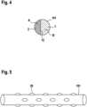
Die Doppellumenkanüle ist bevorzugt mit zumindest einen echographischen und/oder röntgensichtbaren Marker versehen. Ein echographischer Marker kann dabei durch eine echogene Oberflächenstruktur erzeugt werden. Geeignet sind Noppen und/oder Einbuchtungen auf der Oberfläche des Kanülenkörpers. Wie in
Das generelle Behandlungsprinzip der Rechtsherzunterstützung ist in der
BezugszeichenlisteReference symbol list
- 11
- abführendes Lumenefferent lumen
- 22
- zuführendes Lumenafferent lumen
- 33
- untere Hohlveneinferior vena cava
- 44
- Perforationen im abführenden Lumen (Bereich untere Hohlvene)Perforations in the draining lumen (inferior vena cava area)
- 55
- TrikuspidalklappeTricuspid valve
- 66
- Perforationen im abführenden Lumen (Bereich rechter Vorhof)Perforations in the efferent lumen (right atrium area)
- 77
- rechter Vorhofright atrial
- 88th
- rechter Ventrikelright ventricle
- 99
- PulmonalklappePulmonary valve
- 1010
- PulmonalarteriePulmonary artery
- 1111
- Kanülenspitze mit Perforationen zuführendes Lumen (Bereich Pulmonalarterie)Cannula tip with perforations supplying lumen (pulmonary artery area)
- 1212
- Trennung von zuführendem Lumen und abführendem Lumen durch gerades SeptumSeparation of afferent lumen and efferent lumen by a straight septum
- 1313
- Kanülenanteil ohne LumenCannula portion without lumen
- 1414
- zuführende Kanüle, erster Hohlkörperfeeding cannula, first hollow body
- 1515
- anatomische Darstellung untere Hohlvene (Centerline Rekonstruktion CT-Datensatz)anatomical representation of the inferior vena cava (centerline reconstruction CT data set)
- 1616
- anatomische Darstellung Eingang rechter Vorhof (Centerline Rekonstruktion CT-Datensatz)anatomical representation of the entrance to the right atrium (centerline reconstruction CT data set)
- 1717
- anatomische Darstellung rechter Ventrikel/ Trikuspidalklappe (Centerline Rekonstruktion CT-Datensatz)anatomical representation of the right ventricle/tricuspid valve (centerline reconstruction CT data set)
- 1818
- anatomische Darstellung rechter Ventrikel/ rechtsventrikuläre Ausflussbahn (Centerline Rekonstruktion CT-Datensatz)anatomical representation of the right ventricle/right ventricular outflow tract (centerline reconstruction CT data set)
- 1919
- anatomische Darstellung Pulmonalklappe (Centerline Rekonstruktion CT-Datensatz)anatomical representation of the pulmonary valve (centerline reconstruction CT data set)
- 2020
- anatomische Darstellung Pulmonalhauptstamm (Centerline Rekonstruktion CT-Datensatz)anatomical representation of the main pulmonary trunk (centerline reconstruction CT data set)
- 2121
- anatomische Darstellung linke Pulmonalarterie (Centerline Rekonstruktion CT-Datensatz)anatomical representation of the left pulmonary artery (centerline reconstruction CT data set)
- 2222
- anatomischer Bereich untere Hohlveneanatomical area inferior vena cava
- 2323
- anatomischer Bereich rechter Vorhof/ rechter Ventrikelanatomical area right atrium/right ventricle
- 2424
- anatomischer Bereich Pulmonalarterieanatomical area pulmonary artery
- 2525
- Noppennubs
- AA
- Länge abführende KanüleLength of draining cannula
- Bb
- Länge zuführende KanüleLength feeding cannula
- WW
- Wendepunkt der s-förmigen Konfiguration, Übergang zwischen distalem Abschnitt und mittlerem AbschnittTurning point of the s-shaped configuration, transition between distal section and middle section
- 100100
- DoppellumenkanüleDouble lumen cannula
- 101101
- KanülenkörperCannula body
- 102102
- distales Ende der Doppellumenkanüledistal end of the double lumen cannula
- 102a102a
- distales Ende des ersten Hohlkörpersdistal end of the first hollow body
- 102b102b
- distales Ende des zweiten Hohlkörpersdistal end of the second hollow body
- 103103
- proximales Ende der Doppellumenkanüleproximal end of the double lumen cannula
- 103a103a
- proximales Ende des ersten Hohlkörpersproximal end of the first hollow body
- 103b103b
- proximales Ende des zweiten Hohlkörpersproximal end of the second hollow body
- 104104
- Seitenwand des KanülenkörpersSide wall of the cannula body
- 141141
- abführende Kanüle, zweiter Hohlkörperdraining cannula, second hollow body
- 202202
- distaler Abschnitt des Kanülenkörpersdistal section of the cannula body
- 203203
- proximaler Abschnitt des Kanülenkörpersproximal section of the cannula body
- 205205
- mittlerer Abschnitt des Kanülenkörpersmiddle section of the cannula body
- 603603
- erster Bogen der s-förmigen Konfigurationfirst arch of the s-shaped configuration
- 605605
- zweiter Bogen der s-förmigen Konfigurationsecond arch of the s-shaped configuration
ZITATE ENTHALTEN IN DER BESCHREIBUNGQUOTES INCLUDED IN THE DESCRIPTION
Diese Liste der vom Anmelder aufgeführten Dokumente wurde automatisiert erzeugt und ist ausschließlich zur besseren Information des Lesers aufgenommen. Die Liste ist nicht Bestandteil der deutschen Patent- bzw. Gebrauchsmusteranmeldung. Das DPMA übernimmt keinerlei Haftung für etwaige Fehler oder Auslassungen.This list of documents listed by the applicant was generated automatically and is included solely for the better information of the reader. The list is not part of the German patent or utility model application. The DPMA assumes no liability for any errors or omissions.
Zitierte PatentliteraturCited patent literature
- US 8562519 B1 [0003]US 8562519 B1 [0003]
- EP 3200859 B1 [0003]EP 3200859 B1 [0003]
- DE 102020202401 A1 [0003]DE 102020202401 A1 [0003]
- US 20130158338 A1 [0003]US 20130158338 A1 [0003]
- EP 3162394 B1 [0003]EP 3162394 B1 [0003]
Claims (16)
Translated fromGermanPriority Applications (1)
| Application Number | Priority Date | Filing Date | Title |
|---|---|---|---|
| DE102022111626.3ADE102022111626A1 (en) | 2022-05-10 | 2022-05-10 | DOUBLE LUMEN CANNULA |
Applications Claiming Priority (1)
| Application Number | Priority Date | Filing Date | Title |
|---|---|---|---|
| DE102022111626.3ADE102022111626A1 (en) | 2022-05-10 | 2022-05-10 | DOUBLE LUMEN CANNULA |
Publications (1)
| Publication Number | Publication Date |
|---|---|
| DE102022111626A1true DE102022111626A1 (en) | 2023-11-16 |
Family
ID=88510171
Family Applications (1)
| Application Number | Title | Priority Date | Filing Date |
|---|---|---|---|
| DE102022111626.3APendingDE102022111626A1 (en) | 2022-05-10 | 2022-05-10 | DOUBLE LUMEN CANNULA |
Country Status (1)
| Country | Link |
|---|---|
| DE (1) | DE102022111626A1 (en) |
Cited By (1)
| Publication number | Priority date | Publication date | Assignee | Title |
|---|---|---|---|---|
| CN118161690A (en)* | 2024-05-11 | 2024-06-11 | 中国人民解放军总医院第六医学中心 | ECMO system with dual lumen arterial cannula |
Citations (5)
| Publication number | Priority date | Publication date | Assignee | Title |
|---|---|---|---|---|
| US20130158338A1 (en) | 2011-12-19 | 2013-06-20 | Cardiacassist, Inc. | Dual Lumen Cannula |
| US8562519B2 (en) | 2009-12-31 | 2013-10-22 | Cardiacassist, Inc. | Pumping system and method for assisting a patient's heart |
| EP3200859B1 (en) | 2014-10-02 | 2019-11-20 | CardiacAssist, Inc. | Va ecmo with pulmonary artery ventilation |
| EP3162394B1 (en) | 2014-06-26 | 2019-12-25 | Samsung Life Public Welfare Foundation | Integrated double cannula for ecmo |
| DE102020202401A1 (en) | 2020-02-25 | 2021-08-26 | Free Life Medical Gmbh | System for supplying and withdrawing blood and assembly process |
- 2022
- 2022-05-10DEDE102022111626.3Apatent/DE102022111626A1/enactivePending
Patent Citations (5)
| Publication number | Priority date | Publication date | Assignee | Title |
|---|---|---|---|---|
| US8562519B2 (en) | 2009-12-31 | 2013-10-22 | Cardiacassist, Inc. | Pumping system and method for assisting a patient's heart |
| US20130158338A1 (en) | 2011-12-19 | 2013-06-20 | Cardiacassist, Inc. | Dual Lumen Cannula |
| EP3162394B1 (en) | 2014-06-26 | 2019-12-25 | Samsung Life Public Welfare Foundation | Integrated double cannula for ecmo |
| EP3200859B1 (en) | 2014-10-02 | 2019-11-20 | CardiacAssist, Inc. | Va ecmo with pulmonary artery ventilation |
| DE102020202401A1 (en) | 2020-02-25 | 2021-08-26 | Free Life Medical Gmbh | System for supplying and withdrawing blood and assembly process |
Cited By (1)
| Publication number | Priority date | Publication date | Assignee | Title |
|---|---|---|---|---|
| CN118161690A (en)* | 2024-05-11 | 2024-06-11 | 中国人民解放军总医院第六医学中心 | ECMO system with dual lumen arterial cannula |
Similar Documents
| Publication | Publication Date | Title |
|---|---|---|
| DE60308293T2 (en) | Blood treatment catheter device | |
| DE69736610T2 (en) | COLLABORABLE EXHAUST CATHETER | |
| DE69916244T2 (en) | BREATHER FOR BENDED CANNULA | |
| DE69938002T2 (en) | DEVICE FOR INTRAVASCULARLY MOUNTING A CANNULA AND APPLICATION METHOD | |
| DE69828561T2 (en) | DEVICES FOR CLOSING THE ASCENDING AORTA OF A PATIENT | |
| DE69108561T2 (en) | PERCUTANEOUS TRANSSEPTAL CANNULATION SYSTEM OF THE SINISTRUM ATRIUM. | |
| DE602004010104T2 (en) | FLEXIBLE INTAKE SLIDE WITH DIFFERENT DUROMETER | |
| DE69724605T2 (en) | CATHETER WITH A CURVE WITH INCREASING RADIUS | |
| DE60307599T2 (en) | MULTILUMEN CATHETER FOR MINIMIZING LINERIES | |
| DE69825451T2 (en) | CANNULA WITH SEVERAL CABLES | |
| DE60225431T2 (en) | DIALYSIS CATHETER | |
| EP3188769B1 (en) | Catheter | |
| DE69829554T2 (en) | OVALGEFORTME HEART CANNULA | |
| DE69629418T2 (en) | Coronary sinus catheter | |
| DE3853058T2 (en) | Three-lumen catheter. | |
| DE69421717T2 (en) | catheter | |
| DE68920461T2 (en) | Double lumen catheter. | |
| DE10261575A1 (en) | Device for cannulating a blood-carrying vessel and its use for cannulating blood-carrying vessels | |
| DE60015742T2 (en) | MEDICAL ELECTRODE LINE | |
| EP2918249A2 (en) | Supraclavicular catheter system for transseptal access to the left atrium and left ventricle | |
| DE69019886T2 (en) | Catheters and instruments for extracorporeal circulation. | |
| EP1894593B1 (en) | Device for introducing a cannula into a blood vessel | |
| EP2829226B1 (en) | Perfusion cannula with integrated sensors | |
| AT516899A1 (en) | The cannula assembly | |
| DE102022111626A1 (en) | DOUBLE LUMEN CANNULA |