DE102022110416A1 - Connecting device for connecting two functional parts to form a functional unit, functional unit and glasses with such a connecting device - Google Patents
Connecting device for connecting two functional parts to form a functional unit, functional unit and glasses with such a connecting deviceDownload PDFInfo
- Publication number
- DE102022110416A1 DE102022110416A1DE102022110416.8ADE102022110416ADE102022110416A1DE 102022110416 A1DE102022110416 A1DE 102022110416A1DE 102022110416 ADE102022110416 ADE 102022110416ADE 102022110416 A1DE102022110416 A1DE 102022110416A1
- Authority
- DE
- Germany
- Prior art keywords
- contact surface
- magnetic
- magnet
- imaginary
- designed
- Prior art date
- Legal status (The legal status is an assumption and is not a legal conclusion. Google has not performed a legal analysis and makes no representation as to the accuracy of the status listed.)
- Pending
Links
- 239000011521glassSubstances0.000titleclaimsdescription37
- 238000013459approachMethods0.000claimsabstractdescription3
- 238000007789sealingMethods0.000claimsdescription14
- 230000008878couplingEffects0.000claimsdescription7
- 238000010168coupling processMethods0.000claimsdescription7
- 238000005859coupling reactionMethods0.000claimsdescription7
- 239000012530fluidSubstances0.000claimsdescription5
- 239000000843powderSubstances0.000claimsdescription5
- 238000001746injection mouldingMethods0.000claimsdescription3
- 239000002184metalSubstances0.000claimsdescription3
- 238000011161developmentMethods0.000description12
- 238000000926separation methodMethods0.000description4
- 230000007423decreaseEffects0.000description2
- 239000007789gasSubstances0.000description2
- 239000008187granular materialSubstances0.000description2
- 239000007788liquidSubstances0.000description2
- 238000004519manufacturing processMethods0.000description2
- 238000012986modificationMethods0.000description2
- 230000004048modificationEffects0.000description2
- 230000015572biosynthetic processEffects0.000description1
- 238000005352clarificationMethods0.000description1
- 238000011109contaminationMethods0.000description1
- 230000001419dependent effectEffects0.000description1
- 238000013461designMethods0.000description1
- 230000009969flowable effectEffects0.000description1
- 230000005415magnetizationEffects0.000description1
- 239000000126substanceSubstances0.000description1
Images


Classifications
- G—PHYSICS
- G02—OPTICS
- G02C—SPECTACLES; SUNGLASSES OR GOGGLES INSOFAR AS THEY HAVE THE SAME FEATURES AS SPECTACLES; CONTACT LENSES
- G02C5/00—Constructions of non-optical parts
- G02C5/22—Hinges
- G02C5/2209—Pivot bearings and hinge bolts other than screws
- A—HUMAN NECESSITIES
- A45—HAND OR TRAVELLING ARTICLES
- A45C—PURSES; LUGGAGE; HAND CARRIED BAGS
- A45C13/00—Details; Accessories
- A45C13/005—Hinges
- A—HUMAN NECESSITIES
- A45—HAND OR TRAVELLING ARTICLES
- A45C—PURSES; LUGGAGE; HAND CARRIED BAGS
- A45C13/00—Details; Accessories
- A45C13/10—Arrangement of fasteners
- A45C13/1069—Arrangement of fasteners magnetic
- A—HUMAN NECESSITIES
- A45—HAND OR TRAVELLING ARTICLES
- A45C—PURSES; LUGGAGE; HAND CARRIED BAGS
- A45C13/00—Details; Accessories
- A45C13/30—Straps; Bands
- F—MECHANICAL ENGINEERING; LIGHTING; HEATING; WEAPONS; BLASTING
- F16—ENGINEERING ELEMENTS AND UNITS; GENERAL MEASURES FOR PRODUCING AND MAINTAINING EFFECTIVE FUNCTIONING OF MACHINES OR INSTALLATIONS; THERMAL INSULATION IN GENERAL
- F16B—DEVICES FOR FASTENING OR SECURING CONSTRUCTIONAL ELEMENTS OR MACHINE PARTS TOGETHER, e.g. NAILS, BOLTS, CIRCLIPS, CLAMPS, CLIPS OR WEDGES; JOINTS OR JOINTING
- F16B1/00—Devices for securing together, or preventing relative movement between, constructional elements or machine parts
- G—PHYSICS
- G02—OPTICS
- G02C—SPECTACLES; SUNGLASSES OR GOGGLES INSOFAR AS THEY HAVE THE SAME FEATURES AS SPECTACLES; CONTACT LENSES
- G02C5/00—Constructions of non-optical parts
- G02C5/22—Hinges
- G02C5/2263—Composite hinges, e.g. for varying the inclination of the lenses
- H—ELECTRICITY
- H01—ELECTRIC ELEMENTS
- H01R—ELECTRICALLY-CONDUCTIVE CONNECTIONS; STRUCTURAL ASSOCIATIONS OF A PLURALITY OF MUTUALLY-INSULATED ELECTRICAL CONNECTING ELEMENTS; COUPLING DEVICES; CURRENT COLLECTORS
- H01R13/00—Details of coupling devices of the kinds covered by groups H01R12/70 or H01R24/00 - H01R33/00
- H01R13/62—Means for facilitating engagement or disengagement of coupling parts or for holding them in engagement
- H01R13/6205—Two-part coupling devices held in engagement by a magnet
- F—MECHANICAL ENGINEERING; LIGHTING; HEATING; WEAPONS; BLASTING
- F16—ENGINEERING ELEMENTS AND UNITS; GENERAL MEASURES FOR PRODUCING AND MAINTAINING EFFECTIVE FUNCTIONING OF MACHINES OR INSTALLATIONS; THERMAL INSULATION IN GENERAL
- F16B—DEVICES FOR FASTENING OR SECURING CONSTRUCTIONAL ELEMENTS OR MACHINE PARTS TOGETHER, e.g. NAILS, BOLTS, CIRCLIPS, CLAMPS, CLIPS OR WEDGES; JOINTS OR JOINTING
- F16B2200/00—Constructional details of connections not covered for in other groups of this subclass
- F16B2200/83—Use of a magnetic material
- F—MECHANICAL ENGINEERING; LIGHTING; HEATING; WEAPONS; BLASTING
- F16—ENGINEERING ELEMENTS AND UNITS; GENERAL MEASURES FOR PRODUCING AND MAINTAINING EFFECTIVE FUNCTIONING OF MACHINES OR INSTALLATIONS; THERMAL INSULATION IN GENERAL
- F16L—PIPES; JOINTS OR FITTINGS FOR PIPES; SUPPORTS FOR PIPES, CABLES OR PROTECTIVE TUBING; MEANS FOR THERMAL INSULATION IN GENERAL
- F16L37/00—Couplings of the quick-acting type
- F16L37/004—Couplings of the quick-acting type using magnets
- G—PHYSICS
- G02—OPTICS
- G02C—SPECTACLES; SUNGLASSES OR GOGGLES INSOFAR AS THEY HAVE THE SAME FEATURES AS SPECTACLES; CONTACT LENSES
- G02C11/00—Non-optical adjuncts; Attachment thereof
- G02C11/10—Electronic devices other than hearing aids
- G—PHYSICS
- G02—OPTICS
- G02C—SPECTACLES; SUNGLASSES OR GOGGLES INSOFAR AS THEY HAVE THE SAME FEATURES AS SPECTACLES; CONTACT LENSES
- G02C2200/00—Generic mechanical aspects applicable to one or more of the groups G02C1/00 - G02C5/00 and G02C9/00 - G02C13/00 and their subgroups
- G02C2200/02—Magnetic means
- G—PHYSICS
- G02—OPTICS
- G02C—SPECTACLES; SUNGLASSES OR GOGGLES INSOFAR AS THEY HAVE THE SAME FEATURES AS SPECTACLES; CONTACT LENSES
- G02C2200/00—Generic mechanical aspects applicable to one or more of the groups G02C1/00 - G02C5/00 and G02C9/00 - G02C13/00 and their subgroups
- G02C2200/18—Adjustment ridges or notches
- G—PHYSICS
- G02—OPTICS
- G02C—SPECTACLES; SUNGLASSES OR GOGGLES INSOFAR AS THEY HAVE THE SAME FEATURES AS SPECTACLES; CONTACT LENSES
- G02C2200/00—Generic mechanical aspects applicable to one or more of the groups G02C1/00 - G02C5/00 and G02C9/00 - G02C13/00 and their subgroups
- G02C2200/20—Friction elements
Landscapes
- Physics & Mathematics (AREA)
- Health & Medical Sciences (AREA)
- General Physics & Mathematics (AREA)
- Ophthalmology & Optometry (AREA)
- Optics & Photonics (AREA)
- Engineering & Computer Science (AREA)
- General Engineering & Computer Science (AREA)
- Mechanical Engineering (AREA)
- Details Of Connecting Devices For Male And Female Coupling (AREA)
- Pivots And Pivotal Connections (AREA)
Abstract
Translated fromGermanDescription
Translated fromGermanDie Erfindung betrifft eine Verbindungsvorrichtung zur Verbindung zweier Funktionsteile zu einer Funktionseinheit, eine Funktionseinheit mit einer solchen Verbindungsvorrichtung und eine Brille mit einer solchen Verbindungsvorrichtung.The invention relates to a connecting device for connecting two functional parts to form a functional unit, a functional unit with such a connecting device and a pair of glasses with such a connecting device.
Verbindungsvorrichtungen, beispielsweise in Form von Brillenscharnieren, sind typischerweise nicht einfach zu lösen, insbesondere wenn sie als Scharnierachse eine Schraube aufweisen oder in sonstiger Weise verschraubt sind. Ein Brillenbügel ist dann beispielsweise nur mit einigem Aufwand von einem Mittelteil einer Brille zu lösen, wenn er zum Beispiel unter Designaspekten getauscht werden soll. Verbindungsvorrichtungen, die sich stirnseitig anziehende Magnete umfassen, sind zwar einfach und schnell lösbar, haben aber den Nachteil einer geringen Spalt-Toleranz, was bedeutet, dass die Anziehungskraft zwischen den Magneten bereits beim Auftreten eines selbst geringen Spalts zwischen den beiden miteinander verbundenen Funktionsteilen, sei es durch Fertigungstoleranzen, Verschmutzungen, Unachtsamkeit, oder auch eine gezielte Manipulation - beispielsweise beim Verschwenken eines Brillenbügels zwischen einer Ruheposition und einer Trageposition, stark abnimmt, sodass die Verbindung leicht versehentlich gelöst werden kann. Daher qualifiziert sich eine solche Verbindungsvorrichtung insbesondere nicht für Anwendungen, bei denen ein erhöhtes Maß an Funktionssicherheit und Stabilität verlangt wird. Die hier beschriebenen Probleme sind keinesfalls auf den Bereich von Brillen beschränkt, diese werden lediglich nur beispielhaft zur Verdeutlichung erwähnt.Connecting devices, for example in the form of eyeglass hinges, are typically not easy to release, especially if they have a screw as the hinge axis or are screwed together in some other way. For example, a glasses temple can only be removed from the middle part of a pair of glasses with some effort if it is to be replaced, for example for design reasons. Although connecting devices that include magnets that attract each other on the front side can be released easily and quickly, they have the disadvantage of a low gap tolerance, which means that the attractive force between the magnets occurs when even a small gap occurs between the two functional parts connected to one another It decreases significantly due to manufacturing tolerances, contamination, carelessness, or even targeted manipulation - for example when pivoting the arm of a glasses between a rest position and a wearing position, so that the connection can easily be accidentally released. Therefore, such a connection device is particularly not suitable for applications in which an increased level of functional reliability and stability is required. The problems described here are by no means limited to the area of glasses; they are only mentioned as examples for clarification.
Der Erfindung liegt daher die Aufgabe zugrunde, eine Verbindungsvorrichtung zur Verbindung zweier Funktionsteile zu einer Funktionseinheit, eine Funktionseinheit mit einer solchen Verbindungsvorrichtung und eine Brille mit einer solchen Verbindungsvorrichtung zu schaffen, wobei die genannten Nachteile nicht auftreten.The invention is therefore based on the object of creating a connecting device for connecting two functional parts to form a functional unit, a functional unit with such a connecting device and a pair of glasses with such a connecting device, whereby the disadvantages mentioned do not occur.
Die Aufgabe wird gelöst, indem die vorliegende technische Lehre bereitgestellt wird, insbesondere die Lehre der unabhängigen Ansprüche sowie der in den abhängigen Ansprüchen und der Beschreibung offenbarten Ausführungsformen.The object is achieved by providing the present technical teaching, in particular the teaching of the independent claims and the embodiments disclosed in the dependent claims and the description.
Die Aufgabe wird insbesondere gelöst, indem eine Verbindungsvorrichtung zur Verbindung zweier Funktionsteile zu einer Funktionseinheit geschaffen wird. Die Verbindungsvorrichtung weist ein erstes Verbindungsteil mit einer ersten Magnetvorrichtung auf. Die erste Magnetvorrichtung umgreift eine gedachte Verbindungsachse der Verbindungsvorrichtung zumindest segmentweise entlang einer gedachten Umfangslinie, wobei das erste Verbindungsteil im Bereich der gedachten Verbindungsachse einen von der ersten Magnetvorrichtung umgriffenen Eingriffsraum mit einer lichten Weite von höchstens 10 cm aufweist. Die erste Magnetvorrichtung weist mindestens zwei verschiedene erste magnetische Pole auf, die entlang der gedachten Verbindungsachse hintereinander angeordnet sind. Die Verbindungsvorrichtung weist außerdem ein zweites Verbindungsteil mit einer zweiten Magnetvorrichtung auf, wobei die zweite Magnetvorrichtung mindestens zwei verschiedene zweite magnetische Pole aufweist, die entlang einer Längsachse der zweiten Magnetvorrichtung hintereinander angeordnet sind. Die zweite Magnetvorrichtung ist auf die erste Magnetvorrichtung abgestimmt und eingerichtet, um mit der in Richtung der gedachten Verbindungsachse ausgerichteten Längsachse entlang der gedachten Verbindungsachse in den Eingriffsraum einzugreifen, während die ersten magnetischen Pole und die zweiten magnetischen Pole derart relativ zueinander orientiert sind, dass bei einer Annäherung der zweiten Magnetvorrichtung an die erste Magnetvorrichtung entlang der gedachten Verbindungsachse eine Abstoßungskraft überwunden werden muss, um die zweite Magnetvorrichtung in den Eingriffsraum einzuführen. Der Eingriffsraum ist derart ausgebildet, dass die zweite Magnetvorrichtung in den Eingriffsraum zumindest so weit eingreifen kann, dass eine Anziehungskraft zwischen den ersten magnetischen Polen und den zweiten magnetischen Polen wirkt. Vorteilhaft ist auf diese Weise eine Verbindungsvorrichtung bereitgestellt, die einfach und schnell gelöst werden kann, insbesondere ohne ein Werkzeug wie beispielsweise einen Schraubendreher einsetzen zu müssen. Es genügt schlicht, die zweite Magnetvorrichtung gegen die Haltekraft aus dem Eingriffsraum herauszuziehen. Aufgrund der hier spezifisch vorgeschlagenen Anordnung der ersten magnetischen Pole und der zweiten magnetischen Pole relativ zueinander ist die Verbindung aber zugleich sehr stabil, da die Anziehungskraft zwischen den Magnetvorrichtungen nicht bereits beim Auftreten eines kleinen Spalts zwischen den Funktionsteilen sofort abnimmt, vielmehr gegebenenfalls zunächst zunimmt.The object is achieved in particular by creating a connecting device for connecting two functional parts to form a functional unit. The connecting device has a first connecting part with a first magnet device. The first magnetic device encompasses an imaginary connecting axis of the connecting device at least in segments along an imaginary circumferential line, wherein the first connecting part in the area of the imaginary connecting axis has an engagement space encompassed by the first magnetic device with a clear width of at most 10 cm. The first magnetic device has at least two different first magnetic poles, which are arranged one behind the other along the imaginary connection axis. The connecting device also has a second connecting part with a second magnet device, wherein the second magnet device has at least two different second magnetic poles which are arranged one behind the other along a longitudinal axis of the second magnet device. The second magnetic device is coordinated with the first magnetic device and is set up to engage in the engagement space along the imaginary connection axis with the longitudinal axis aligned in the direction of the imaginary connection axis, while the first magnetic poles and the second magnetic poles are oriented relative to one another in such a way that at one Approaching the second magnet device to the first magnet device along the imaginary connection axis, a repulsive force must be overcome in order to introduce the second magnet device into the engagement space. The engagement space is designed such that the second magnetic device can engage in the engagement space at least to such an extent that an attractive force acts between the first magnetic poles and the second magnetic poles. In this way, a connecting device is advantageously provided that can be released easily and quickly, in particular without having to use a tool such as a screwdriver. It is simply sufficient to pull the second magnetic device out of the engagement space against the holding force. However, due to the arrangement of the first magnetic poles and the second magnetic poles relative to one another specifically proposed here, the connection is at the same time very stable, since the attractive force between the magnetic devices does not immediately decrease when a small gap occurs between the functional parts, but rather initially increases if necessary.
Unter einer lichten Weite wird im Kontext der hier vorliegenden technischen Lehre insbesondere ein Durchmesser, eine Kantenlänge, oder ein kleinster Abstand zwischen zwei Kanten des Eingriffsraums verstanden. Insbesondere ist die lichte Weite ein Maß dafür, welche Abmessung ein Objekt, insbesondere die zweite Magnetvorrichtung, haben darf, um noch in den Eingriffsraum eingeführt werden zu können.In the context of the technical teaching here, a clear width is understood to mean, in particular, a diameter, an edge length, or a smallest distance between two edges of the engagement space. In particular, the clear width is a measure of what dimensions an object, in particular the second magnet device, may have in order to still be able to be inserted into the engagement space.
Unter zwei verschiedenen magnetischen Polen einer Magnetvorrichtung werden im Kontext der vorliegenden technischen Lehre insbesondere die beiden verschiedennamigen Pole eines Magneten verstanden, die aufgrund der Nichtexistenz magnetischer Monopole stets gemeinsam auftreten müssen. Insbesondere sind die zwei verschiedenen magnetischen Pole einer Magnetvorrichtung einerseits ein magnetischer Nordpol und andererseits ein magnetischer Südpol. Jede Magnetvorrichtung weist also zumindest einen Nordpol und zumindest einen Südpol auf. Es ist möglich, dass zumindest eine Magnetvorrichtung, ausgewählt aus der ersten Magnetvorrichtung und der zweiten Magnetvorrichtung, eine Mehrzahl solcher Polpaare aus Nordpol N und Südpol S aufweist, insbesondere eine Mehrzahl von jeweils entlang der zugeordneten Achse, ausgewählt aus der gedachten Verbindungsachse und der Längsachse, - voneinander beabstandet oder unmittelbar aufeinanderfolgend - hintereinander angeordneten Polpaaren, beispielsweise bei drei Polepaaren die Abfolge NSNSNS.In the context of the present technical teaching, two different magnetic poles of a magnetic device are understood to mean, in particular, the two poles of a magnet with different names, which may be due to the non-existence netical monopolies must always appear together. In particular, the two different magnetic poles of a magnetic device are, on the one hand, a magnetic north pole and, on the other hand, a magnetic south pole. Each magnetic device therefore has at least one north pole and at least one south pole. It is possible for at least one magnet device, selected from the first magnet device and the second magnet device, to have a plurality of such pole pairs consisting of north pole N and south pole S, in particular a plurality of each along the associated axis, selected from the imaginary connection axis and the longitudinal axis, - spaced apart or immediately following one another - pole pairs arranged one behind the other, for example with three pole pairs the sequence NSNSNS.
Insbesondere sind die zwei verschiedenen ersten magnetischen Pole entlang der gedachten Verbindungsachse unmittelbar hintereinander angeordnet. Insbesondere sind die zwei verschiedenen zweiten magnetischen Pole entlang der Längsachse unmittelbar hintereinander angeordnet.In particular, the two different first magnetic poles are arranged directly one behind the other along the imaginary connection axis. In particular, the two different second magnetic poles are arranged directly one behind the other along the longitudinal axis.
Insbesondere ist die zweite Magnetvorrichtung auf die erste Magnetvorrichtung abgestimmt und eingerichtet, um mit der Längsachse, die mit der gedachten Verbindungsachse zusammenfällt, entlang der gedachten Verbindungsachse in den Eingriffsraum einzugreifen. Das bedeutet insbesondere, dass die zweite Magnetvorrichtung derart in den Eingriffsraum eingeführt wird, dass die Längsachse mit der gedachten Verbindungsachse zusammenfällt.In particular, the second magnet device is matched to the first magnet device and is set up to engage in the engagement space along the imaginary connection axis with the longitudinal axis, which coincides with the imaginary connection axis. This means in particular that the second magnet device is inserted into the engagement space in such a way that the longitudinal axis coincides with the imaginary connection axis.
Insbesondere weist die Verbindungsvorrichtung genau zwei Verbindungsteile, das heißt nur zwei Verbindungsteile, auf. Weiterhin weist die Verbindungsvorrichtung insbesondere genau zwei Magnetvorrichtungen, das heißt nur zwei Magnetvorrichtungen, auf. Die Verbindungsvorrichtung ist somit insgesamt sehr einfach aufgebaut und umfasst nur wenige Teile. Dadurch ist sie zugleich leicht zu bedienen. Die Verbindung der Verbindungsteile miteinander zu der Funktionseinheit beruht insbesondere ausschließlich auf der magnetischen Anziehungskraft der beiden Magnetvorrichtungen. Sonstige etwaige magnetische Eigenschaften weiterer Bestandteile der Verbindungsteile - über die Magnetvorrichtungen hinaus -, insbesondere eine Magnetisierbarkeit oder Magnetisierung, sind bevorzugt für die Verbindungsfunktion der Verbindungsvorrichtung irrelevant. Insbesondere weisen die Verbindungsteile in einer Ausführungsform außer den beiden Magnetvorrichtungen keine weiteren magnetischen oder magnetisierbaren Teile oder Elemente auf.In particular, the connecting device has exactly two connecting parts, that is to say only two connecting parts. Furthermore, the connecting device has in particular exactly two magnet devices, that is to say only two magnet devices. The connecting device is therefore very simple overall and comprises only a few parts. This makes it easy to use at the same time. The connection of the connecting parts to one another to form the functional unit is based in particular exclusively on the magnetic attraction of the two magnetic devices. Any other magnetic properties of other components of the connecting parts - beyond the magnetic devices -, in particular magnetizability or magnetization, are preferably irrelevant for the connecting function of the connecting device. In particular, in one embodiment the connecting parts have no further magnetic or magnetizable parts or elements apart from the two magnetic devices.
Eine Axialrichtung ist im Kontext der vorliegenden technischen Lehre stets - je nach konkretem Kontext - eine Richtung, in welche die Verbindungsachse und/oder die Längsachse weist. Eine Umfangsrichtung umgreift die Axialrichtung konzentrisch. Eine radiale Richtung steht senkrecht auf der Axialrichtung.In the context of the present technical teaching, an axial direction is always - depending on the specific context - a direction in which the connecting axis and/or the longitudinal axis points. A circumferential direction encompasses the axial direction concentrically. A radial direction is perpendicular to the axial direction.
Gemäß einer Weiterbildung der Erfindung ist vorgesehen, dass das erste Verbindungsteil eine erste Kontaktfläche aufweist, wobei das zweite Verbindungsteil eine zweite Kontaktfläche aufweist, wobei die erste Kontaktfläche und die zweite Kontaktfläche aufeinander abgestimmt und eingerichtet sind, um aneinander zu liegen.According to a further development of the invention, it is provided that the first connecting part has a first contact surface, the second connecting part having a second contact surface, the first contact surface and the second contact surface being coordinated with one another and set up to lie against one another.
In einer Ausführungsform begrenzen die erste Kontaktfläche und die zweite Kontaktfläche eine Eingreiftiefe der zweiten Magnetvorrichtung in den Eingriffsraum, wenn die zweite Magnetvorrichtung in den Eingriffsraum eingreift. Insbesondere kann die zweite Magnetvorrichtung nicht weiter in den Eingriffsraum eintauchen, wenn die zweite Kontaktfläche an der ersten Kontaktfläche anliegt. Auf diese Weise wird vorteilhaft insbesondere eine definierte Lage der ersten Magnetvorrichtung und der zweiten Magnetvorrichtung relativ zueinander bereitgestellt, sodass insbesondere auch die in verbundenem Zustand wirksame Anziehungskraft definiert ist.In one embodiment, the first contact surface and the second contact surface limit an engagement depth of the second magnet device in the engagement space when the second magnet device engages in the engagement space. In particular, the second magnetic device cannot penetrate any further into the engagement space when the second contact surface is in contact with the first contact surface. In this way, a defined position of the first magnetic device and the second magnetic device relative to one another is advantageously provided, so that in particular the attractive force that is effective in the connected state is also defined.
Alternativ verbleibt in einer Ausführungsform im verbundenen Zustand ein Spalt zwischen der ersten Kontaktfläche und der zweiten Kontaktfläche. In diesem Fall schwebt gleichsam die zweite Magnetvorrichtung in der ersten Magnetvorrichtung. Dabei verbleibt ein gewisses Spiel zwischen den beiden Verbindungsteilen.Alternatively, in one embodiment, a gap remains between the first contact surface and the second contact surface in the connected state. In this case, the second magnet device, as it were, floats in the first magnet device. A certain amount of play remains between the two connecting parts.
Gemäß einer Weiterbildung der Erfindung ist vorgesehen, dass die erste Kontaktfläche und die zweite Kontaktfläche derart auf die erste Magnetvorrichtung und die zweite Magnetvorrichtung abgestimmt sind, dass eine erste Trennebene zwischen den ersten magnetischen Polen und eine zweite Trennebene zwischen den zweiten magnetischen Polen einen endlichen Abstand voneinander aufweisen, wenn die erste Kontaktfläche und die zweite Kontaktfläche aneinander anliegen, wobei eine Anziehungskraft zwischen den ersten magnetischen Polen und den zweiten magnetischen Polen wirkt, die die erste Kontaktfläche und die zweite Kontaktfläche gegeneinander drängt. Insbesondere ist die erste Kontaktfläche derart relativ zu der ersten Magnetvorrichtung angeordnet, und die zweite Kontaktfläche ist derart relativ zu der zweiten Magnetvorrichtung angeordnet, dass die erste Trennebene zwischen den ersten magnetischen Polen und die zweite Trennebene zwischen den zweiten magnetischen Polen einen endlichen Abstand voneinander aufweisen, wenn die erste Kontaktfläche und die zweite Kontaktfläche aneinander anliegen, wobei eine Anziehungskraft zwischen den ersten magnetischen Polen und den zweiten magnetischen Polen wirkt, die die erste Kontaktfläche und die zweite Kontaktfläche gegeneinander drängt. Durch den Versatz der Trennebenen wird vorteilhaft gewährleistet, dass die Anziehungskraft auch im verbundenen Zustand herrscht und für eine definierte und stabile Anlage der Kontaktflächen aneinander sorgt. Dabei wird den beiden Magnetvorrichtungen nicht erlaubt, ihre energetisch minimale Lage relativ zueinander einzunehmen, vielmehr wird das Erreichen dieser Lage durch die Anlage der Kontaktflächen aneinander behindert.According to a further development of the invention, it is provided that the first contact surface and the second contact surface are matched to the first magnetic device and the second magnetic device in such a way that a first separating plane between the first magnetic poles and a second separating plane between the second magnetic poles are at a finite distance from one another have when the first contact surface and the second contact surface rest against one another, an attractive force acting between the first magnetic poles and the second magnetic poles, which forces the first contact surface and the second contact surface against one another. In particular, the first contact surface is arranged relative to the first magnetic device, and the second contact surface is arranged relative to the second magnetic device, such that the first separation plane between the first magnetic poles and the second separation plane between the second magnetic poles have a finite distance from one another, when the first contact surface and the second contact surface abut each other, an attractive force between the first magnetic poles and the second magnetic poles acts, which pushes the first contact surface and the second contact surface against each other. The offset of the parting planes advantageously ensures that the attractive force also prevails in the connected state and ensures a defined and stable contact between the contact surfaces. The two magnetic devices are not allowed to assume their energetically minimal position relative to one another; rather, reaching this position is hindered by the contact surfaces being in contact with one another.
Demgegenüber fluchten bei einer Ausgestaltung, bei der im verbundenen Zustand noch ein Spalt zwischen den Kontaktflächen besteht, die Trennebenen miteinander, und die zweite Magnetvorrichtung schwebt kräftefrei in der ersten Magnetvorrichtung. In diesem Fall herrscht zwar im verbundenen Zustand keine Anziehungskraft mehr zwischen den Magnetvorrichtungen, die Verbindungsteile können aber nur voneinander getrennt werden, indem die energetisch minimale Lage der Magnetvorrichtungen relativ zueinander verlassen wird, wobei im Fall einer Auslenkung der Trennebenen aus der miteinander fluchtenden Lage sofort eine Anziehungskraft wirksam wird, die einem Lösen der Verbindungsvorrichtung entgegenwirkt und überwunden werden muss, um die Verbindungsteile voneinander zu lösen.In contrast, in a configuration in which there is still a gap between the contact surfaces in the connected state, the parting planes are aligned with one another, and the second magnetic device floats in the first magnetic device without any force. In this case, although there is no longer any attraction between the magnetic devices in the connected state, the connecting parts can only be separated from one another by leaving the energetically minimal position of the magnetic devices relative to one another, whereby in the event of a deflection of the separating planes from the aligned position, one immediately Attractive force becomes effective, which counteracts loosening of the connecting device and must be overcome in order to release the connecting parts from each other.
Unter einer Trennebene wird im Kontext der hier vorliegenden technischen Lehre insbesondere eine gedachte Ebene verstanden, durch die die zwei verschiedenen Pole einer Magnetvorrichtung voneinander abgeteilt sind, also insbesondere eine gedachte Ebene zwischen dem Nordpol und dem Südpol einer Magnetvorrichtung. Wenn die Trennebenen der beiden Magnetvorrichtungen miteinander fluchten, bedeutet dies somit zugleich, dass der Nordpol der ersten Magnetvorrichtung axial genau auf Höhe des Südpols der zweiten Magnetvorrichtung angeordnet ist, wobei auch der Südpol der ersten Magnetvorrichtung axial genau auf Höhe des Nordpols der zweiten Magnetvorrichtung angeordnet ist. Weisen die Trennebenen demgegenüber bei vorhandener Anziehungskraft einen Versatz zueinander auf, überlappt beispielsweise der Nordpol der ersten Magnetvorrichtung noch teilweise mit dem Nordpol der zweiten Magnetvorrichtung, sodass die energetisch minimale Lage noch nicht erreicht ist.In the context of the technical teaching here, a separating plane is understood to mean, in particular, an imaginary plane through which the two different poles of a magnetic device are separated from one another, i.e. in particular an imaginary plane between the north pole and the south pole of a magnetic device. If the parting planes of the two magnetic devices are aligned with one another, this also means that the north pole of the first magnetic device is arranged axially exactly at the level of the south pole of the second magnetic device, with the south pole of the first magnetic device also being arranged axially exactly at the level of the north pole of the second magnetic device . If, on the other hand, the separating planes are offset from one another when there is an attractive force, for example, the north pole of the first magnetic device still partially overlaps with the north pole of the second magnetic device, so that the energetically minimal position has not yet been reached.
Gemäß einer Weiterbildung der Erfindung ist vorgesehen, dass die erste Kontaktfläche die gedachte Verbindungsachse - in Umfangsrichtung - ringförmig umgreift, wobei die zweite Kontaktfläche die Längsachse - in Umfangsrichtung - ringförmig umgreift, und wobei zumindest eine Kontaktfläche, ausgewählt aus der ersten Kontaktfläche und der zweiten Kontaktfläche, vorzugsweise beide Kontaktflächen, radial außerhalb der jeweils zugeordneten ersten und zweiten magnetischen Pole angeordnet ist. „Radial außerhalb“ bedeutet dabei, dass die Kontaktflächen einen größeren radialen Abstand zu der jeweiligen Achse aufweisen als die magnetischen Pole. Insbesondere sind die beiden Kontaktflächen als Flansche oder Schultern des jeweiligen Verbindungsteils ausgebildet.According to a further development of the invention, it is provided that the first contact surface surrounds the imaginary connection axis in a ring shape - in the circumferential direction -, with the second contact surface surrounding the longitudinal axis - in a ring shape - in the circumferential direction, and at least one contact surface, selected from the first contact surface and the second contact surface , preferably both contact surfaces, is arranged radially outside the respectively assigned first and second magnetic poles. “Radial outside” means that the contact surfaces have a greater radial distance from the respective axis than the magnetic poles. In particular, the two contact surfaces are designed as flanges or shoulders of the respective connecting part.
Alternativ ist vorgesehen, dass die erste Kontaktfläche die gedachte Verbindungsachse - in Umfangsrichtung - ringförmig umgreift, wobei die zweite Kontaktfläche die Längsachse - in Umfangsrichtung - ringförmig umgreift, und wobei zumindest eine Kontaktfläche, ausgewählt aus der ersten Kontaktfläche und der zweiten Kontaktfläche, vorzugsweise beide Kontaktflächen, radial innerhalb der jeweils zugeordneten ersten und zweiten magnetischen Pole angeordnet ist. „Radial innerhalb“ bedeutet dabei, dass die Kontaktflächen einen kleineren radialen Abstand zu der jeweiligen Achse aufweisen als die magnetischen Pole. Insbesondere sind die beiden Kontaktflächen als Flansche oder Schultern des jeweiligen Verbindungsteils ausgebildet.Alternatively, it is provided that the first contact surface surrounds the imaginary connection axis in a ring shape - in the circumferential direction -, with the second contact surface surrounding the longitudinal axis - in a ring shape - in the circumferential direction, and at least one contact surface, selected from the first contact surface and the second contact surface, preferably both contact surfaces , is arranged radially within the respectively assigned first and second magnetic poles. “Radial within” means that the contact surfaces have a smaller radial distance from the respective axis than the magnetic poles. In particular, the two contact surfaces are designed as flanges or shoulders of the respective connecting part.
Gemäß einer Weiterbildung der Erfindung ist vorgesehen, dass zumindest eine Kontaktfläche, ausgewählt aus der ersten Kontaktfläche und der zweiten Kontaktfläche, eine - insbesondere elastische - Dichtungsvorrichtung aufweist. Insbesondere ist zumindest an einer Kontaktfläche, ausgewählt aus der ersten Kontaktfläche und der zweiten Kontaktfläche, eine - insbesondere elastische - Dichtungsvorrichtung angeordnet ist. Auf diese Weise kann vorteilhaft die Verbindung zwischen den Verbindungsteilen dicht, insbesondere fluiddicht oder mediendicht, insbesondere gasdicht oder flüssigkeitsdicht, ausgestaltet werden. Die Verbindungsvorrichtung kann dann insbesondere zum Durchleiten von Fluiden oder Medien, insbesondere Gasen, Flüssigkeiten oder fließfähigen körnigen Materialien wie Pulvern, eingerichtet sein. Alternativ kann die Verbindungsvorrichtung zum fluiddichten oder mediendichten Aufbewahren von Stoffen oder Objekten, insbesondere Gasen, Flüssigkeiten oder körnigen Materialien wie Pulvern, eingerichtet sein. Es ist insbesondere auch möglich, dass die Dichtungsvorrichtung eine der Kontaktflächen bildet, oder dass eine der Kontaktflächen an der Dichtungsvorrichtung angeordnet ist.According to a further development of the invention, it is provided that at least one contact surface, selected from the first contact surface and the second contact surface, has a - in particular elastic - sealing device. In particular, a - in particular elastic - sealing device is arranged at least on one contact surface, selected from the first contact surface and the second contact surface. In this way, the connection between the connecting parts can advantageously be designed to be tight, in particular fluid-tight or media-tight, in particular gas-tight or liquid-tight. The connecting device can then be set up in particular for the passage of fluids or media, in particular gases, liquids or flowable granular materials such as powders. Alternatively, the connecting device can be set up for fluid-tight or media-tight storage of substances or objects, in particular gases, liquids or granular materials such as powders. In particular, it is also possible for the sealing device to form one of the contact surfaces, or for one of the contact surfaces to be arranged on the sealing device.
Alternativ oder zusätzlich ist vorgesehen, dass die erste Kontaktfläche und die zweite Kontaktfläche elektrisch leitend ausgebildet sind Die Verbindungsvorrichtung kann dann insbesondere als elektrische Verbindungsvorrichtung eingerichtet sein, wobei ein elektrischer Kontakt über die beiden Kontaktflächen hergestellt werden kann. In einer Ausführungsform sind zusätzlich die Magnetvorrichtungen elektrisch leitend und bevorzugt elektrisch kontaktiert. Sie stehen dann in verbundenem Zustand der Verbindungsvorrichtung in mechanischem Kontakt miteinander, um einen zweiten elektrischen Kontakt zusätzlich zu dem ersten elektrischen Kontakt der Kontaktflächen herzustellen.Alternatively or additionally, it is provided that the first contact surface and the second contact surface are designed to be electrically conductive. The connecting device can then be set up in particular as an electrical connecting device, wherein an electrical contact can be established via the two contact surfaces. In one embodiment, the magnetic devices are additionally electrically conductive and preferably electrically contacted. They are then in a connected state Connecting device in mechanical contact with each other to establish a second electrical contact in addition to the first electrical contact of the contact surfaces.
Ist die Verbindungsvorrichtung als Scharnier ausgebildet oder weist eine Scharnierfunktion auf, sind die Verbindungsteile insbesondere um die gedachte Verbindungsachse relativ zueinander drehbar.If the connecting device is designed as a hinge or has a hinge function, the connecting parts can be rotated relative to one another in particular about the imaginary connecting axis.
Gemäß einer Weiterbildung der Erfindung ist vorgesehen, dass die erste Kontaktfläche und die zweite Kontaktfläche korrespondierende Rastelemente zur Definition vorbestimmter Winkelpositionen des ersten Verbindungsteils relativ zu dem zweiten Verbindungsteil um die gedachte Verbindungsachse aufweisen. Insbesondere wenn die Verbindungsvorrichtung als Scharnier ausgebildet ist oder eine Scharnierfunktion aufweist, können auf diese Weise vorteilhaft bestimmte Winkelpositionen vordefiniert werden.According to a further development of the invention, it is provided that the first contact surface and the second contact surface have corresponding locking elements for defining predetermined angular positions of the first connecting part relative to the second connecting part about the imaginary connecting axis. Particularly if the connecting device is designed as a hinge or has a hinge function, certain angular positions can advantageously be predefined in this way.
In einer Ausführungsform weist eine Kontaktfläche, ausgewählt aus der ersten Kontaktfläche und der zweiten Kontaktfläche, mindestens eine Aussparung oder Vertiefung als ein erstes Rastelement auf, wobei die andere Kontaktfläche, ausgewählt aus der zweiten Kontaktfläche und der ersten Kontaktfläche, mindestens eine Erhebung oder mindestens einen Vorsprung als ein zweites Rastelement aufweist. Es ist möglich, dass eine Mehrzahl miteinander korrespondierender Vorsprünge oder Erhebungen einerseits sowie Aussparungen oder Vertiefungen andererseits vorgesehen sind.In one embodiment, a contact surface, selected from the first contact surface and the second contact surface, has at least one recess or recess as a first locking element, wherein the other contact surface, selected from the second contact surface and the first contact surface, has at least one elevation or at least one projection as a second locking element. It is possible for a plurality of corresponding projections or elevations on the one hand and recesses or depressions on the other to be provided.
Alternativ oder zusätzlich ist vorgesehen, dass die erste Kontaktfläche und die zweite Kontaktfläche korrespondierende Anschlagelemente zur Begrenzung einer Drehbarkeit des ersten Verbindungsteils relativ zu dem zweiten Verbindungsteil um die gedachte Verbindungsachse aufweisen. Insbesondere wenn die Verbindungsvorrichtung als Scharnier ausgebildet ist oder eine Scharnierfunktion aufweist, können auf diese Weise vorteilhaft definierte Anschläge zur Begrenzung der Drehbarkeit bereitgestellt werden.Alternatively or additionally, it is provided that the first contact surface and the second contact surface have corresponding stop elements to limit rotation of the first connecting part relative to the second connecting part about the imaginary connecting axis. In particular if the connecting device is designed as a hinge or has a hinge function, advantageously defined stops can be provided in this way to limit the rotation.
In einer Ausführungsform weisen die Kontaktflächen jeweils eine Stufe als die jeweiligen korrespondierenden Anschlagelemente auf.In one embodiment, the contact surfaces each have a step as the respective corresponding stop elements.
Gemäß einer Weiterbildung der Erfindung ist vorgesehen, dass die erste Magnetvorrichtung und die zweite Magnetvorrichtung derart ausgebildet und aufeinander abgestimmt sind, dass sie keinen mechanischen Kontakt zueinander haben, wenn die zweite Magnetvorrichtung in den Eingriffsraum eingreift. Vorteilhaft wird auf diese Weise eine Reibung und damit ein reibungsbedingter Verschleiß im Bereich der Magnetvorrichtungen vermieden, was insbesondere vorteilhaft ist, wenn die Verbindungsvorrichtung als Scharnier ausgebildet ist oder eine Scharnierfunktion aufweist. Vorteilhaft sind dabei auch die Fertigungstoleranzen der Magnetvorrichtungen weniger ausschlaggebend für eine gute Funktionsfähigkeit des Scharniers.According to a further development of the invention, it is provided that the first magnet device and the second magnet device are designed and coordinated with one another in such a way that they have no mechanical contact with one another when the second magnet device engages in the engagement space. In this way, friction and thus friction-related wear in the area of the magnet devices are advantageously avoided, which is particularly advantageous if the connecting device is designed as a hinge or has a hinge function. It is also advantageous that the manufacturing tolerances of the magnetic devices are less crucial for the good functionality of the hinge.
Insbesondere - aber nicht darauf beschränkt - bei einer Ausgestaltung der Verbindungsvorrichtung als Scharnier wird bevorzugt eine definierte Reibung durch die wirkenden Magnetkräfte im Bereich der Kontaktflächen bereitgestellt, insbesondere um eine Gangregulierung des Scharniers zu bewirken, insbesondere eine Leicht- oder Schwergängigkeit des Scharniers einzustellen. Insbesondere bei einer Anwendung als Brillenscharnier kann auf diese Weise vorteilhaft vermieden werden, dass ein über die Verbindungsvorrichtung mit einem Mittelteil der Brille verbundener Brillenbügel unkontrolliert aus einer Trageposition in eine Ruheposition fällt.In particular - but not limited to - in an embodiment of the connecting device as a hinge, a defined friction is preferably provided by the acting magnetic forces in the area of the contact surfaces, in particular in order to regulate the speed of the hinge, in particular to adjust the ease or sluggishness of the hinge. Particularly when used as a spectacle hinge, it can be advantageously avoided in this way that a spectacle arm connected to a middle part of the spectacles via the connecting device falls uncontrollably from a wearing position into a rest position.
Gemäß einer Weiterbildung der Erfindung ist vorgesehen, dass die erste Magnetvorrichtung als in Umfangsrichtung geschlossener Ring ausgebildet ist.According to a further development of the invention, it is provided that the first magnetic device is designed as a ring that is closed in the circumferential direction.
Alternativ ist vorgesehen, dass die erste Magnetvorrichtung eine Mehrzahl an Magnetsegmenten aufweist.Alternatively, it is provided that the first magnet device has a plurality of magnet segments.
Weiter alternativ ist vorgesehen, dass die erste Magnetvorrichtung als Platte mit mindestens einer zumindest bereichsweise den Eingriffsraum bildenden Aussparung ausgebildet ist.As a further alternative, it is provided that the first magnetic device is designed as a plate with at least one recess which forms the engagement space at least in some areas.
In einer Ausführungsform ist in dem von der ersten Magnetvorrichtung umgriffenen Eingriffsraum mindestens ein erster elektrischer Kontakt angeordnet, der insbesondere eingerichtet ist, um elektrisch mit einem zweiten elektrischen Kontakt des zweiten Verbindungsteils, insbesondere im Bereich der zweiten Magnetvorrichtung, verbunden zu werden.In one embodiment, at least one first electrical contact is arranged in the engagement space encompassed by the first magnet device, which is in particular designed to be electrically connected to a second electrical contact of the second connecting part, in particular in the area of the second magnet device.
Gemäß einer Weiterbildung der Erfindung ist vorgesehen, dass die zweite Magnetvorrichtung als Stabmagnet ausgebildet ist.According to a further development of the invention it is provided that the second magnetic device is designed as a bar magnet.
Alternativ ist vorgesehen, dass die zweite Magnetvorrichtung als in Umfangsrichtung geschlossener Ring ausgebildet ist.Alternatively, it is provided that the second magnet device is designed as a ring that is closed in the circumferential direction.
Weiter alternativ ist vorgesehen, dass die zweite Magnetvorrichtung eine Mehrzahl an Magnetsegmenten aufweist.As a further alternative, it is provided that the second magnet device has a plurality of magnet segments.
In einer Ausführungsform ist mindestens ein zweiter elektrischer Kontakt radial innerhalb der als in Umfangsrichtung geschlossener Ring ausgebildeten oder eine Mehrzahl an Magnetsegmenten aufweisenden zweiten Magnetvorrichtung angeordnet. Alternativ durchgreift der mindestens eine zweite elektrische Kontakt die als in Umfangsrichtung geschlossener Ring ausgebildete oder eine Mehrzahl an Magnetsegmenten aufweisende zweite Magnetvorrichtung. Der mindestens eine zweite elektrische Kontakt ist insbesondere eingerichtet, um elektrisch mit dem ersten elektrischen Kontakt des ersten Verbindungsteils, insbesondere im Bereich der ersten Magnetvorrichtung, verbunden zu werden.In one embodiment, at least a second electrical contact is located radially within the magnet segments, which are designed as a ring closed in the circumferential direction, or a plurality of magnet segments pointing second magnet device arranged. Alternatively, the at least one second electrical contact passes through the second magnet device, which is designed as a ring that is closed in the circumferential direction or has a plurality of magnet segments. The at least one second electrical contact is in particular designed to be electrically connected to the first electrical contact of the first connecting part, in particular in the area of the first magnet device.
Gemäß einer Weiterbildung der Erfindung ist vorgesehen, dass zumindest eine Magnetvorrichtung, ausgewählt aus der ersten Magnetvorrichtung und der zweiten Magnetvorrichtung, in einem Metallpulver-Spritzgussverfahren hergestellt ist. Vorteilhaft kann die zumindest eine Magnetvorrichtung auf diese Weise sehr flexibel mit gewünschter Formgebung hergestellt werden, wobei insbesondere auch starke Permanentmagneten erhalten werden können.According to a further development of the invention, it is provided that at least one magnet device, selected from the first magnet device and the second magnet device, is produced in a metal powder injection molding process. Advantageously, the at least one magnet device can be manufactured very flexibly in this way with the desired shape, and in particular strong permanent magnets can also be obtained.
Gemäß einer Weiterbildung der Erfindung ist vorgesehen, dass die lichte Weite des Eingriffsraums höchstens 9 cm, insbesondere höchstens 8 cm, insbesondere höchstens 7 cm, insbesondere höchstens 6 cm, insbesondere höchstens 5 cm, insbesondere höchstens 4 cm, insbesondere höchstens 3 cm, insbesondere höchstens 2 cm, insbesondere höchstens 1,5 cm, insbesondere höchstens 1 cm, insbesondere höchstens 5 mm, insbesondere höchstens 4 mm, insbesondere höchstens 3 mm, insbesondere höchstens 2 mm, insbesondere höchstens 1 mm, beträgt.According to a further development of the invention, it is provided that the clear width of the engagement space is at most 9 cm, in particular at most 8 cm, in particular at most 7 cm, in particular at most 6 cm, in particular at most 5 cm, in particular at most 4 cm, in particular at most 3 cm, in particular at most 2 cm, in particular at most 1.5 cm, in particular at most 1 cm, in particular at most 5 mm, in particular at most 4 mm, in particular at most 3 mm, in particular at most 2 mm, in particular at most 1 mm.
Gemäß einer Weiterbildung der Erfindung ist vorgesehen, dass die Verbindungsvorrichtung ausgebildet ist als ein Element, ausgewählt aus einer Gruppe, bestehend aus: Einem Scharnier, einer Fluidleitungskupplung, insbesondere Schlauchkupplung, insbesondere zur Verbindung zweier Abschnitte einer Vakuum- oder Unterdruckleitung, einer Steckverbindung, insbesondere einer elektrischen Steckverbindung, einem Verschluss, insbesondere für einen Deckel, insbesondere für einen schwenkbaren Deckel, und einem Clipsverbinder, insbesondere zum Anklipsen eines Tragegurts.According to a further development of the invention, it is provided that the connecting device is designed as an element selected from a group consisting of: a hinge, a fluid line coupling, in particular a hose coupling, in particular for connecting two sections of a vacuum or negative pressure line, a plug connection, in particular one electrical plug connection, a closure, in particular for a lid, in particular for a pivoting lid, and a clip connector, in particular for clipping on a carrying strap.
Gemäß einer Weiterbildung der Erfindung ist vorgesehen, dass die erste Magnetvorrichtung mechanisch mit einem ersten Grundkörper des ersten Verbindungsteils verbunden ist. Alternativ oder zusätzlich ist die zweite Magnetvorrichtung mechanisch mit einem zweiten Grundkörper des zweiten Verbindungsteils verbunden. Auf diese Weise sind die Verbindungsteile insbesondere einteilig handhabbar, sodass die Bedienung der Verbindungsvorrichtung sehr einfach und unkompliziert ist. Insbesondere weist die Verbindungsvorrichtung lediglich die beiden einteilig handhabbaren Verbindungsteile auf, die miteinander verbunden werden können. Es bedarf also insbesondere keiner zusätzlichen Teile, um die Verbindung der Verbindungsteile herzustellen.According to a further development of the invention, it is provided that the first magnet device is mechanically connected to a first base body of the first connecting part. Alternatively or additionally, the second magnet device is mechanically connected to a second base body of the second connecting part. In this way, the connecting parts can be handled in particular in one piece, so that the operation of the connecting device is very simple and uncomplicated. In particular, the connecting device only has the two connecting parts that can be handled in one piece and that can be connected to one another. In particular, no additional parts are required to establish the connection of the connecting parts.
Die Aufgabe wird auch gelöst, indem eine Funktionseinheit geschaffen wird, die ein erstes Funktionsteil, ein zweites Funktionsteil und eine erfindungsgemäße Verbindungsvorrichtung oder eine Verbindungsvorrichtung nach einer oder mehreren der zuvor beschriebenen Ausführungsformen aufweist, wobei das erste Verbindungsteil an dem ersten Funktionsteil angeordnet ist, und wobei das zweite Verbindungsteil an dem zweiten Funktionsteil angeordnet ist. In Zusammenhang mit der Funktionseinheit ergeben sich insbesondere die Vorteile, die bereits zuvor in Zusammenhang mit der Verbindungsvorrichtung erläutert wurden.The object is also achieved by creating a functional unit which has a first functional part, a second functional part and a connecting device according to the invention or a connecting device according to one or more of the previously described embodiments, wherein the first connecting part is arranged on the first functional part, and where the second connecting part is arranged on the second functional part. In connection with the functional unit, there are in particular the advantages that have already been explained previously in connection with the connecting device.
Insbesondere ist das erste Verbindungsteil mit dem ersten Funktionsteil - lösbar oder unlösbar - mechanisch verbunden. Insbesondere bilden das erste Verbindungsteil und das erste Funktionsteil ein einteilig handhabbares erstes Verbindungselement. Alternativ oder zusätzlich ist das zweite Verbindungsteil mit dem zweiten Funktionsteil - lösbar oder unlösbar - mechanisch verbunden. Insbesondere bilden das zweite Verbindungsteil und das zweite Funktionsteil ein einteilig handhabbares zweites Verbindungselement. Insbesondere weist die Funktionseinheit lediglich die beiden einteilig handhabbaren Verbindungselemente auf, die miteinander zu der Funktionseinheit verbunden werden können. Es bedarf also insbesondere keiner zusätzlichen Teile, um die Funktionseinheit aus den Verbindungselementen herzustellen.In particular, the first connecting part is mechanically connected - detachably or non-detachably - to the first functional part. In particular, the first connecting part and the first functional part form a first connecting element that can be handled in one piece. Alternatively or additionally, the second connecting part is mechanically connected - detachably or non-detachably - to the second functional part. In particular, the second connecting part and the second functional part form a second connecting element that can be handled in one piece. In particular, the functional unit only has the two connecting elements that can be handled in one piece and can be connected to one another to form the functional unit. In particular, no additional parts are required to produce the functional unit from the connecting elements.
Insbesondere bilden das erste Verbindungselement und das zweite Verbindungselement gemeinsam die Funktionseinheit.In particular, the first connecting element and the second connecting element together form the functional unit.
Die Aufgabe wird auch gelöst, indem eine Brille geschaffen wird, die mindestens eine erfindungsgemäße Verbindungsvorrichtung oder mindestens eine Verbindungsvorrichtung nach einer oder mehreren der zuvor beschriebenen Ausführungsformen aufweist. In Zusammenhang mit der Brille ergeben sich insbesondere die Vorteile, die bereits zuvor in Zusammenhang mit der Verbindungsvorrichtung oder mit der Funktionseinheit erläutert wurden.The object is also achieved by creating glasses which have at least one connecting device according to the invention or at least one connecting device according to one or more of the previously described embodiments. In connection with the glasses, there are in particular the advantages that have already been explained previously in connection with the connection device or with the functional unit.
Insbesondere ist die Brille eine erfindungsgemäße Funktionseinheit oder eine Funktionseinheit nach einer oder mehreren der zuvor beschriebenen Ausführungsformen. Dabei kann beispielsweise das Mittelteil das erste Funktionsteil und der Brillenbügel das zweite Funktionsteil sein.In particular, the glasses are a functional unit according to the invention or a functional unit according to one or more of the previously described embodiments. For example, the middle part can be the first functional part and the temple of the glasses can be the second functional part.
Insbesondere ist die Verbindungsvorrichtung in einer ersten Ausführungsform der Brille als Scharnier zwischen einem Brillenbügel und einem Mittelteil der Brille ausgebildet.In particular, the connecting device in a first embodiment of the glasses is in the form of a group Nier formed between a temple and a middle part of the glasses.
Insbesondere weist die Brille zwei erfindungsgemäße Verbindungsvorrichtungen oder zwei Verbindungsvorrichtungen nach einer oder mehreren der zuvor beschriebenen Ausführungsformen auf. Dabei ist eine erste Verbindungsvorrichtung der beiden Verbindungsvorrichtungen als Scharnier zwischen einem ersten Brillenbügel und dem Mittelteil der Brille ausgebildet, und eine zweite Verbindungsvorrichtung der beiden Verbindungsvorrichtungen ist als Scharnier zwischen einem zweiten Brillenbügel und dem Mittelteil der Brille ausgebildet.In particular, the glasses have two connecting devices according to the invention or two connecting devices according to one or more of the previously described embodiments. A first connecting device of the two connecting devices is designed as a hinge between a first temple of the glasses and the middle part of the glasses, and a second connecting device of the two connecting devices is designed as a hinge between a second temple of the glasses and the middle part of the glasses.
In einer zweiten Ausführungsform der Brille ist die Verbindungsvorrichtung insbesondere als Steckverbinder oder Clipsverbinder zum Verbinden einer Zusatzvorrichtung, beispielsweise einer Kamera, insbesondere einer sogenannten Head-Cam, mit der Brille ausgebildet.In a second embodiment of the glasses, the connecting device is designed in particular as a plug connector or clip connector for connecting an additional device, for example a camera, in particular a so-called head cam, to the glasses.
Der Steckverbinder ist insbesondere an dem Brillenbügel oder dem Mittelteil der Brille angeordnet.The connector is arranged in particular on the temple of the glasses or the middle part of the glasses.
Die Erfindung wird im Folgenden anhand der Zeichnung näher erläutert. Dabei zeigen
1 eine schematische Darstellung eines ersten Ausführungsbeispiels einer Verbindungsvorrichtung;2 eine Darstellung eines zweiten Ausführungsbeispiels einer Verbindungsvorrichtung;3 eine Darstellung eines ersten Ausführungsbeispiels einer Funktionseinheit mit einem dritten Ausführungsbeispiel einer Verbindungsvorrichtung;4 eine Darstellung eines zweiten Ausführungsbeispiels einer Funktionseinheit mit einem vierten Ausführungsbeispiel einer Verbindungsvorrichtung;5 eine schematische Darstellung eines dritten Ausführungsbeispiels einer Funktionseinheit mit einem fünften Ausführungsbeispiel einer Verbindungsvorrichtung;6 eine schematische Darstellung eines vierten Ausführungsbeispiels einer Funktionseinheit mit einem sechsten Ausführungsbeispiel einer Verbindungsvorrichtung;7A ,7B eine schematische Detail-Darstellung eines ersten Ausführungsbeispiels einer Brille als einer Funktionseinheit mit einem siebten Ausführungsbeispiel einer Verbindungsvorrichtung, und eine Abwandlung davon, und8 eine schematische Darstellung eines zweiten Ausführungsbeispiels einer Brille als einer Funktionseinheit mit einem achten Ausführungsbeispiel einer Verbindungsvorrichtung.
1 a schematic representation of a first embodiment of a connection device;2 a representation of a second embodiment of a connecting device;3 a representation of a first exemplary embodiment of a functional unit with a third exemplary embodiment of a connecting device;4 a representation of a second exemplary embodiment of a functional unit with a fourth exemplary embodiment of a connecting device;5 a schematic representation of a third exemplary embodiment of a functional unit with a fifth exemplary embodiment of a connecting device;6 a schematic representation of a fourth exemplary embodiment of a functional unit with a sixth exemplary embodiment of a connecting device;7A ,7B a schematic detailed representation of a first exemplary embodiment of glasses as a functional unit with a seventh exemplary embodiment of a connecting device, and a modification thereof, and8th a schematic representation of a second embodiment of glasses as a functional unit with an eighth embodiment of a connecting device.
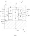
Insbesondere muss beim Einführen der zweiten Magnetvorrichtung 17 in den Eingriffsraum 11 und damit in die erste Magnetvorrichtung 9 erst einmal die Abstoßungskraft der zunächst einander entlang der Verbindungsachse A zugewandten, gleichnamigen magnetischen Pole überwunden werden, bei dem hier konkret dargestellten Beispiel die Abstoßungskraft zwischen dem zweiten magnetischen Südpol 19.2 und dem ersten magnetischen Südpol 13.2. Erst wenn die zweite Magnetvorrichtung 17 hinreichend tief in den Eingriffsraum 11 eingreift, wird eine Anziehungskraft wirksam, bei dem konkret dargestellten Beispiel zwischen einerseits dem zweiten magnetischen Südpol 19.2 und dem ersten magnetischen Nordpol 13.1, und andererseits zwischen dem zweiten magnetischen Nordpol 19.1 und dem ersten magnetischen Südpol 13.2. Die beiden Magnetvorrichtungen 9, 17 streben eine Endlage in einem energetischen Minimum - oder gleichbedeutend Potentialminimum - dort an, wo eine erste Trennebene 21 zwischen den ersten magnetischen Polen 13 und eine zweite Trennebene 23 zischen den zweiten magnetischen Polen 19 miteinander fluchten.In particular, when inserting the
Bei dem hier dargestellten ersten Ausführungsbeispiel weist das erste Verbindungsteil 7 eine erste Kontaktfläche 25 auf, und das zweite Verbindungsteil 15 weist eine zweite Kontaktfläche 27 auf. Die erste Kontaktfläche 25 und die zweite Kontaktfläche 27 sind aufeinander abgestimmt und eingerichtet, um aneinander zu liegen und insbesondere eine Eingreiftiefe der zweiten Magnetvorrichtung 17 in den Eingriffsraum 11 zu begrenzen, wenn die zweite Magnetvorrichtung 17 in den Eingriffsraum 11 eingreift.In the first exemplary embodiment shown here, the first connecting
Dabei sind die erste Kontaktfläche 25 und die zweite Kontaktfläche 27 derart auf die erste Magnetvorrichtung 9 und die zweite Magnetvorrichtung 17 abgestimmt, dass die erste Trennebene 21 zwischen den ersten magnetischen Polen 13 und die zweite Trennebene 23 zwischen den zweiten magnetischen Polen 19 einen endlichen Abstand voneinander aufweisen, wenn die erste Kontaktfläche 25 und die zweite Kontaktfläche 27 aneinander anliegen. Dabei drängt die Anziehungskraft zwischen den ersten magnetischen Polen 13 und den zweiten magnetischen Polen 19 die erste Kontaktfläche 25 und die zweite Kontaktfläche 27 gegeneinander. Die Kontaktflächen 25, 27 verhindern demnach, dass die Magnetvorrichtungen 9, 17 die Lage ihres energetischen Minimums erreichen. Somit bleibt die Anziehungskraft auch im verbundenen Zustand der Verbindungsteile 7, 15 bestehen.The
Insbesondere umgreift die erste Kontaktfläche 25 die gedachte Verbindungsachse A ringförmig, und die zweite Kontaktfläche 27 umgreift die Längsachse L ringförmig.In particular, the
Bei dem hier dargestellten, ersten Ausführungsbeispiel sind beide Kontaktflächen 25, 27 radial außerhalb der jeweils zugeordneten ersten und zweiten magnetischen Pole 13, 19 angeordnet.In the first exemplary embodiment shown here, both contact surfaces 25, 27 are arranged radially outside the respectively assigned first and second magnetic poles 13, 19.
Die erste Magnetvorrichtung 9 und die zweite Magnetvorrichtung 17 sind insbesondere derart ausgebildet und aufeinander abgestimmt, dass sie keinen mechanischen Kontakt zueinander haben, wenn die zweite Magnetvorrichtung 17 in den Eingriffsraum 11 eingreift.The
Bevorzugt ist die erste Magnetvorrichtung 9 als in Umfangsrichtung geschlossener Ring ausgebildet ist. Bei einem anderen, nicht dargestellten Ausführungsbeispiel ist es aber auch möglich, dass die erste Magnetvorrichtung 9 als Platte mit mindestens einer zumindest bereichsweise den Eingriffsraum 11 bildenden Aussparung ausgebildet ist.The
Bei dem hier dargestellten ersten Ausführungsbeispiel ist die zweite Magnetvorrichtung 17 als Stabmagnet ausgebildet. Bei einem anderen, nicht dargestellten Ausführungsbeispiel ist es aber auch möglich, dass die zweite Magnetvorrichtung 17 eine Mehrzahl an Magnetsegmenten aufweist.In the first exemplary embodiment shown here, the second
Bevorzugt ist zumindest eine Magnetvorrichtung 9, 17, ausgewählt aus der ersten Magnetvorrichtung 9 und der zweiten Magnetvorrichtung 17, in einem Metallpulver-Spritzgussverfahren hergestellt.Preferably, at least one
Bevorzugt beträgt die lichte Weite des Eingriffsraums 11 höchstens 9 cm, insbesondere höchstens 8 cm, insbesondere höchstens 7 cm, insbesondere höchstens 6 cm, insbesondere höchstens 5 cm, insbesondere höchstens 4 cm, insbesondere höchstens 3 cm, insbesondere höchstens 2 cm, insbesondere höchstens 1,5 cm, insbesondere höchstens 1 cm, insbesondere höchstens 5 mm, insbesondere höchstens 4 mm, insbesondere höchstens 3 mm, insbesondere höchstens 2 mm, insbesondere höchstens 1 mm.The clear width of the
Insbesondere ist die erste Magnetvorrichtung 9 mechanisch mit einem ersten Grundkörper 29 des ersten Verbindungsteils 7 verbunden, und die zweite Magnetvorrichtung 17 ist mechanisch mit einem zweiten Grundkörper 31 des zweiten Verbindungsteils 15 verbunden.In particular, the
Gleiche und funktionsgleiche Elemente sind in allen Figuren mit gleichen Bezugszeichen versehen, sodass insofern jeweils auf die vorangegangene Beschreibung verwiesen wird.Identical and functionally identical elements are provided with the same reference numbers in all figures, so that reference is made to the previous description.
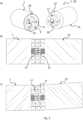
Bei a) sind das erste Verbindungsteil 7 und das zweite Verbindungsteil 15 getrennt voneinander dargestellt.At a), the first connecting
Bei dem zweiten Ausführungsbeispiel ist die Verbindungsvorrichtung 1 als eine erste elektrische Steckverbindung 32 ausgebildet. Die zweite Magnetvorrichtung 17 ist als in Umfangsrichtung geschlossener Ring ausgebildet.In the second exemplary embodiment, the connecting
In dem Eingriffsraum 11 des ersten Verbindungsteils 7 ist mindestens ein erster elektrischer Kontakt 33 - hier drei erste elektrische Kontakte 33 - angeordnet, der insbesondere eingerichtet ist, um elektrisch mit mindestens einem zweiten elektrischen Kontakt 35 des zweiten Verbindungsteils 15 verbunden zu werden.At least one first electrical contact 33 - here three first electrical contacts 33 - is arranged in the
Der mindestens eine zweite elektrische Kontakt 35 - hier drei zweite elektrische Kontakte 35 - ist radial innerhalb der als in Umfangsrichtung geschlossener Ring ausgebildeten zweiten Magnetvorrichtung 17 angeordnet.The at least one second electrical contact 35 - here three second electrical contacts 35 - is arranged radially within the
Bei b) sind die Verbindungsteile 7, 15 miteinander verbunden dargestellt, wie dies in Zusammenhang mit
Bei c) ist schematisch dargestellt, dass die hier vorgeschlagene Verbindungsvorrichtung 1 vorteilhaft eine hohe Toleranz gegenüber einer relativen Verkippung der Verbindungsteile 7, 15 sowie auch gegenüber einer Spaltbildung zwischen den Verbindungsteilen 7, 15 aufweist, wobei die Anziehungskraft zwischen den beiden Magnetvorrichtungen 9, 17 über einen weiten Bereich, insbesondere sowohl einen weiten Winkelbereich als auch einen weiten Toleranzbereich für den Spalt, erhalten bleibt. Somit kann insbesondere eine versehentliche oder anderweitig ungewollte Trennung der Verbindungsteile 7, 15 sicher vermieden werden. Aufgrund der belasteten Kontaktstifte 37 bleibt auch der elektrische Kontakt bei dem hier dargestellten Ausführungsbeispiel vorteilhaft über einen weiten Bereich von Verkippungswinkeln und Spaltbreiten erhalten.At c) it is shown schematically that the connecting
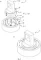
Die Funktionseinheit 5 weist als die Funktionsteile 3 ein erstes Funktionsteil 3.1 und ein zweites Funktionsteil 3.2 auf. Bei dem dargestellten ersten Ausführungsbeispiel ist die Funktionseinheit 5 als Leuchte, insbesondere als LED-Leuchte ausgebildet, wobei die Verbindungsvorrichtung 1 als eine zweite elektrische Steckverbindung 32` ausgebildet ist. Das erste Funktionsteil 3.1 ist als Kontaktiervorrichtung ausgebildet, und das zweite Funktionsteil 3.2 ist als LED ausgebildet. Vorteilhaft ist die LED in der Kontaktiervorrichtung frei drehbar.The
Insbesondere ist das erste Verbindungsteil 7 an dem ersten Funktionsteil 3.1 angeordnet, insbesondere mit dem ersten Funktionsteil 3.1 mechanisch verbunden. Das zweite Verbindungsteil 15 ist an dem zweiten Funktionsteil 3.2 angeordnet, insbesondere mit dem zweiten Funktionsteil 3.2 mechanisch verbunden.In particular, the first connecting
Eine erste elektrische Kontaktierung zwischen dem ersten Funktionsteil 3.1 und dem zweiten Funktionsteil 3.2 wird über eine in dem Eingriffsraum 11 angeordnete elektrische Kontaktfeder 39 einerseits und eine elektrisch leitfähige Bodenplatte 41 des zweiten Funktionsteil 3.2 andererseits hergestellt. Eine zweite elektrische Kontaktierung wird über die in diesem Fall elektrisch leitfähigen und einander im verbundenen Zustand der Verbindungsvorrichtung 1 berührenden Magnetvorrichtungen 9, 17 hergestellt.A first electrical contact between the first functional part 3.1 and the second functional part 3.2 is made via an
Bei diesem dritten Ausführungsbeispiel weist die Verbindungsvorrichtung 1 keine Kontaktflächen 25, 27 auf. Stattdessen wird hier die zweite Magnetvorrichtung 17 gegen die Vorspannkraft der elektrischen Kontaktfeder 39 soweit in den Eingriffsraum 11 hineingezogen, bis die elastische Rückstellkraft der Kontaktfeder 39 gerade gleich der Anziehungskraft zwischen den Magnetvorrichtungen 9, 17 ist. Alternativ ist es aber auch bei diesem Ausführungsbeispiel möglich, dass die Verbindungvorrichtung 1 Kontaktflächen 25, 27 aufweist.In this third exemplary embodiment, the connecting
Die erste Magnetvorrichtung 9 weist bei dem dritten Ausführungsbeispiel der Verbindungsvorrichtung 1 eine Mehrzahl an Magnetsegmenten 43 auf, von denen der besseren Übersichtlichkeit wegen hier nur eines mit einem Bezugszeichen versehen ist.In the third exemplary embodiment of the connecting
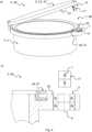
Bei dem vierten Ausführungsbeispiel ist die Verbindungsvorrichtung 1 als Verschluss 46, insbesondere für einen schwenkbaren Deckel 47 der Dose 45 ausgebildet.In the fourth exemplary embodiment, the connecting
Die Verbindungsvorrichtung 1 weist zumindest an einer Kontaktfläche 25, 27, ausgewählt aus der ersten Kontaktfläche 25 und der zweiten Kontaktfläche 27, eine - insbesondere elastische - Dichtungsvorrichtung 49 auf. Insbesondere ist hier an der ersten Kontaktfläche 25 eine Dichtlippe 51 als Dichtungsvorrichtung 49 angeordnet. Im geschlossenen Zustand der Dose 45 wird die Dichtlippe 51 durch die Anziehungskraft der Magnetvorrichtungen 9, 17 zusammengedrückt, sodass die Dose 45 dicht geschlossen ist.The connecting
Insbesondere ist das erste Verbindungsteil 7 in das - insbesondere als ein erstes Schlauchstück ausgebildete - erste Funktionsteil 3.1 eingesteckt, und das zweite Verbindungsteil 15 ist in das - insbesondere als ein zweites Schlauchstück ausgebildete - zweite Funktionsteil 3.2 eingesteckt.In particular, the first connecting
Bei dem hier dargestellten, fünften Ausführungsbeispiel der Verbindungsvorrichtung 1 sind beide Kontaktflächen 25, 27 radial innerhalb der jeweils zugeordneten ersten und zweiten magnetischen Pole 13, 19 angeordnet. Insbesondere ist die Dichtungsvorrichtung 49 an der ersten Kontaktfläche 25 angeordnet.In the fifth exemplary embodiment of the connecting
Die zweite Magnetvorrichtung 17 wird insbesondere so weit in den Eingriffsraum 11 hineingezogen, bis die elastische Rückstellkraft der Dichtungsvorrichtung 49 gleich der Anziehungskraft zwischen den Magnetvorrichtungen 9, 17 ist. Dabei ist es möglich, dass die Kontaktflächen 25, 27 nicht aneinander anliegen, sondern durch die Dichtungsvorrichtung 49 zumindest geringfügig voneinander beabstandet sind. Alternativ könnte man aber auch konstatieren, dass bei dem hier dargestellten Ausführungsbeispiel die Dichtungsvorrichtung 49 die erste Kontaktfläche 25 bildet, oder dass die erste Kontaktfläche 25 an der Dichtungsvorrichtung 49 angeordnet ist.The
Der Medientransport durch die Medienleitung erfolgt insbesondere durch den Eingriffsraum 11 hindurch.The media is transported through the media line in particular through the
Die insbesondere als Fluidleitungskupplung 48 ausgebildete Verbindungsvorrichtung 1 dient bevorzugt dazu, Vakuumsschläuche miteinander zu verbinden oder Medien unter Unterdruck zu leiten. Die an der Verbindungsvorrichtung 1 dann angreifenden Druckkräfte stabilisieren die Verbindung und drängen die Magnetvorrichtungen 9, 17 zusätzlich ineinander beziehungsweise die Kontaktflächen 25, 27 gegeneinander.The connecting
Alternativ oder zusätzlich kann die Verbindungsvorrichtung 1 gleichsam als Überdruckventil dienen, da ein in der Verbindungsvorrichtung 1 auftretender erhöhter Druck zu einer Trennung der Magnetvorrichtungen 9, 17 voneinander führen kann, wenn die Druckkräfte die magnetischen Haltekräfte übersteigen.Alternatively or additionally, the connecting
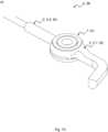
Vorteilhaft erlaubt die Verbindungsvorrichtung 1 eine Verdrehbarkeit des Tragegurts 55 auch im an dem Taschenkörper 57 befestigten Zustand.The connecting
Bei einem anderen, nicht dargestellten Ausführungsbeispiel kann die Verbindungsvorrichtung 1, insbesondere der Clipsverbinder 76, auch separat von dem Tragegurt 55 ausgebildet sein, insbesondere als Lasche, Rechteckring, Schlaufe oder Öse, in die der Tragegurt 55 eingefädelt werden kann.In another exemplary embodiment, not shown, the connecting
Die Verbindungsvorrichtung 1 ist als Scharnier 61 zwischen einem Brillenbügel 63 und einem Mittelteil 65 der Brille 59 ausgebildet.The connecting
Bei c) ist eine Abwandlung des Details des ersten Ausführungsbeispiels der Brille 59 dargestellt. Dabei weisen die erste Kontaktfläche 25 und die zweite Kontaktfläche 27 korrespondierende Rastelemente 71 zur Definition vorbestimmter Winkelpositionen des ersten Verbindungsteils 7 relativ zu dem zweiten Verbindungsteil 15 um die gedachte Verbindungsachse A auf. Insbesondere weist die erste Kontaktfläche 25 mindestens eine Vertiefung 73 - hier insbesondere zwei Vertiefungen 73, von denen jedoch nur eine dem Betrachter zugewandt ist - als ein erstes Rastelement 71.1 auf, wobei die zweite Kontaktfläche 27 mindestens einen Vorsprung 75 - hier insbesondere zwei Vorsprünge 75 - als ein zweites Rastelement 71.2 aufweist. Alternativ oder zusätzlich können bei einem nicht dargestellten Ausführungsbeispiel der Brille 59 auch zusätzliche, insbesondere einerseits in dem Brillenbügel 63 und andererseits in dem Mittelteil 65 oder in den Verbindungsteilen 7, 15 angeordnete, miteinander zusammenwirkende Magnete vorgesehen sein, um bestimmte Winkelpositionen, insbesondere einerseits die Trageposition und andererseits die Ruheposition des Brillenbügels 63, zu definieren.At c) a modification of the detail of the first exemplary embodiment of the glasses 59 is shown. The
Die Verbindungsvorrichtung 1 ist hier insbesondere als ein an einem der Brillenbügel 63 angeordneter Steck- oder Clipsverbinder 76` zum Verbinden einer Zusatzvorrichtung 77, insbesondere einer Head-Cam, mit der Brille 59 ausgebildet. Die Verbindungsvorrichtung 1 kann alternativ oder zusätzlich bei einem hier nicht dargestellten Ausgangsbeispiel auch an dem Mittelteil 65 der Brille 59 angeordnet sein.The connecting
Die vorliegende Offenbarung ist nicht auf die in Zusammenhang mit den Figuren konkret beschriebenen Ausführungsbeispiele beschränkt. Der Fachmann erkennt vielmehr, dass eine Vielzahl von Ausgestaltungen und Kombinationen der beschriebenen Merkmale miteinander in Übereinstimmung mit dem Schutzbereich der angehängten Ansprüche möglich ist.The present disclosure is not limited to the exemplary embodiments specifically described in connection with the figures. Rather, those skilled in the art will recognize that a variety of configurations and combinations of the features described are possible with one another in accordance with the scope of the appended claims.
Claims (15)
Translated fromGermanPriority Applications (3)
| Application Number | Priority Date | Filing Date | Title |
|---|---|---|---|
| DE102022110416.8ADE102022110416A1 (en) | 2022-04-28 | 2022-04-28 | Connecting device for connecting two functional parts to form a functional unit, functional unit and glasses with such a connecting device |
| PCT/EP2023/061135WO2023209104A1 (en) | 2022-04-28 | 2023-04-27 | Connection device for connecting two functional parts in order to form a functional unit, functional unit, and glasses comprising such a connection device |
| EP23720913.5AEP4515324A1 (en) | 2022-04-28 | 2023-04-27 | Connection device for connecting two functional parts in order to form a functional unit, functional unit, and glasses comprising such a connection device |
Applications Claiming Priority (1)
| Application Number | Priority Date | Filing Date | Title |
|---|---|---|---|
| DE102022110416.8ADE102022110416A1 (en) | 2022-04-28 | 2022-04-28 | Connecting device for connecting two functional parts to form a functional unit, functional unit and glasses with such a connecting device |
Publications (1)
| Publication Number | Publication Date |
|---|---|
| DE102022110416A1true DE102022110416A1 (en) | 2023-11-02 |
Family
ID=86286359
Family Applications (1)
| Application Number | Title | Priority Date | Filing Date |
|---|---|---|---|
| DE102022110416.8APendingDE102022110416A1 (en) | 2022-04-28 | 2022-04-28 | Connecting device for connecting two functional parts to form a functional unit, functional unit and glasses with such a connecting device |
Country Status (3)
| Country | Link |
|---|---|
| EP (1) | EP4515324A1 (en) |
| DE (1) | DE102022110416A1 (en) |
| WO (1) | WO2023209104A1 (en) |
Cited By (1)
| Publication number | Priority date | Publication date | Assignee | Title |
|---|---|---|---|---|
| DE102023108697A1 (en)* | 2023-04-05 | 2024-10-10 | Audi Aktiengesellschaft | Method for assembling an air duct arrangement and air duct arrangement |
Citations (1)
| Publication number | Priority date | Publication date | Assignee | Title |
|---|---|---|---|---|
| DE102019003818A1 (en) | 2019-05-31 | 2020-12-03 | Gerhard Kirstein | Coupling device and coupling arrangement |
Family Cites Families (4)
| Publication number | Priority date | Publication date | Assignee | Title |
|---|---|---|---|---|
| US7311526B2 (en)* | 2005-09-26 | 2007-12-25 | Apple Inc. | Magnetic connector for electronic device |
| US9941627B2 (en)* | 2015-09-30 | 2018-04-10 | Apple Inc. | Magnetic surface contacts |
| US11639787B2 (en)* | 2018-06-21 | 2023-05-02 | Taiwan Oasis Technology Co., Ltd. | Magnetic assembly structure |
| FR3113956A1 (en)* | 2020-09-04 | 2022-03-11 | F & H | Fixing device for spectacle frames. |
- 2022
- 2022-04-28DEDE102022110416.8Apatent/DE102022110416A1/enactivePending
- 2023
- 2023-04-27WOPCT/EP2023/061135patent/WO2023209104A1/ennot_activeCeased
- 2023-04-27EPEP23720913.5Apatent/EP4515324A1/enactivePending
Patent Citations (1)
| Publication number | Priority date | Publication date | Assignee | Title |
|---|---|---|---|---|
| DE102019003818A1 (en) | 2019-05-31 | 2020-12-03 | Gerhard Kirstein | Coupling device and coupling arrangement |
Cited By (1)
| Publication number | Priority date | Publication date | Assignee | Title |
|---|---|---|---|---|
| DE102023108697A1 (en)* | 2023-04-05 | 2024-10-10 | Audi Aktiengesellschaft | Method for assembling an air duct arrangement and air duct arrangement |
Also Published As
| Publication number | Publication date |
|---|---|
| EP4515324A1 (en) | 2025-03-05 |
| WO2023209104A1 (en) | 2023-11-02 |
Similar Documents
| Publication | Publication Date | Title |
|---|---|---|
| EP3220781B1 (en) | Closure device for securing an electronic device on a holding device | |
| WO2010006594A2 (en) | Shielded magnetic plug-in lock | |
| DE212012000102U1 (en) | Sealing washer for one connection for three cables | |
| EP4515324A1 (en) | Connection device for connecting two functional parts in order to form a functional unit, functional unit, and glasses comprising such a connection device | |
| EP0667046B1 (en) | Shielded plug with cable connection | |
| DE102014101952A1 (en) | Connector part with a locking element | |
| DE2402915A1 (en) | PLUG CONNECTION WITH SNAP EFFECT | |
| AT523019A1 (en) | Electrical connector | |
| DE2731001A1 (en) | ELECTRIC PLUG-IN SOCKET | |
| EP2658039B1 (en) | Socket | |
| DE19525257C2 (en) | Electrical plug connection with end position locking | |
| DE68917739T2 (en) | TWO-PIECE CONNECTOR. | |
| DE69728326T2 (en) | L-shaped lamp holder | |
| EP4416801B1 (en) | Connector module and method for producing same | |
| DE102011116857B3 (en) | Multi-polar flat plug for attachment to end of connecting cable that is utilized for connecting e.g. smartphone, with data input interface, has bridge cut from plate by movable component of plate, where ends of legs of bridge form hinges | |
| DE2940607A1 (en) | Plug-in fuse unit - has bent H-shaped conductor, with crosspiece as melting point and verticals as flat contacts | |
| EP3510307A1 (en) | Diaphragm valve | |
| DE10016609B4 (en) | Device for connecting a rod to a component | |
| DE1248137B (en) | Contact arrangement in an electrical switch | |
| DE4400478C1 (en) | Two part coupling that can be separated for use with cables | |
| WO2015075129A1 (en) | Plug connector | |
| EP0283696A2 (en) | Elastomeric joint | |
| CH710483A2 (en) | Socket adapter. | |
| DE10148287A1 (en) | Protection against accidental contact for an earthed socket | |
| DE102005058305A1 (en) | Connecting terminal, has contact jaws for connection with busbar that is arranged inside or outside of terminal, and contact surfaces of clamping jaws run perpendicular to extension direction of busbar |
Legal Events
| Date | Code | Title | Description |
|---|---|---|---|
| R012 | Request for examination validly filed |