DE102022001109A1 - Air suspension fork with linearized spring characteristics thanks to a multi-chamber system - Google Patents
Air suspension fork with linearized spring characteristics thanks to a multi-chamber systemDownload PDFInfo
- Publication number
- DE102022001109A1 DE102022001109A1DE102022001109.3ADE102022001109ADE102022001109A1DE 102022001109 A1DE102022001109 A1DE 102022001109A1DE 102022001109 ADE102022001109 ADE 102022001109ADE 102022001109 A1DE102022001109 A1DE 102022001109A1
- Authority
- DE
- Germany
- Prior art keywords
- suspension
- progression
- chambers
- fork
- suspension element
- Prior art date
- Legal status (The legal status is an assumption and is not a legal conclusion. Google has not performed a legal analysis and makes no representation as to the accuracy of the status listed.)
- Withdrawn
Links
Images


Classifications
- B—PERFORMING OPERATIONS; TRANSPORTING
- B62—LAND VEHICLES FOR TRAVELLING OTHERWISE THAN ON RAILS
- B62K—CYCLES; CYCLE FRAMES; CYCLE STEERING DEVICES; RIDER-OPERATED TERMINAL CONTROLS SPECIALLY ADAPTED FOR CYCLES; CYCLE AXLE SUSPENSIONS; CYCLE SIDE-CARS, FORECARS, OR THE LIKE
- B62K25/00—Axle suspensions
- B62K25/04—Axle suspensions for mounting axles resiliently on cycle frame or fork
- B62K25/06—Axle suspensions for mounting axles resiliently on cycle frame or fork with telescopic fork, e.g. including auxiliary rocking arms
- B62K25/08—Axle suspensions for mounting axles resiliently on cycle frame or fork with telescopic fork, e.g. including auxiliary rocking arms for front wheel
- B—PERFORMING OPERATIONS; TRANSPORTING
- B62—LAND VEHICLES FOR TRAVELLING OTHERWISE THAN ON RAILS
- B62K—CYCLES; CYCLE FRAMES; CYCLE STEERING DEVICES; RIDER-OPERATED TERMINAL CONTROLS SPECIALLY ADAPTED FOR CYCLES; CYCLE AXLE SUSPENSIONS; CYCLE SIDE-CARS, FORECARS, OR THE LIKE
- B62K25/00—Axle suspensions
- B62K25/04—Axle suspensions for mounting axles resiliently on cycle frame or fork
- B62K25/28—Axle suspensions for mounting axles resiliently on cycle frame or fork with pivoted chain-stay
- F—MECHANICAL ENGINEERING; LIGHTING; HEATING; WEAPONS; BLASTING
- F16—ENGINEERING ELEMENTS AND UNITS; GENERAL MEASURES FOR PRODUCING AND MAINTAINING EFFECTIVE FUNCTIONING OF MACHINES OR INSTALLATIONS; THERMAL INSULATION IN GENERAL
- F16F—SPRINGS; SHOCK-ABSORBERS; MEANS FOR DAMPING VIBRATION
- F16F9/00—Springs, vibration-dampers, shock-absorbers, or similarly-constructed movement-dampers using a fluid or the equivalent as damping medium
- F16F9/02—Springs, vibration-dampers, shock-absorbers, or similarly-constructed movement-dampers using a fluid or the equivalent as damping medium using gas only or vacuum
- F16F9/0209—Telescopic
- B—PERFORMING OPERATIONS; TRANSPORTING
- B62—LAND VEHICLES FOR TRAVELLING OTHERWISE THAN ON RAILS
- B62K—CYCLES; CYCLE FRAMES; CYCLE STEERING DEVICES; RIDER-OPERATED TERMINAL CONTROLS SPECIALLY ADAPTED FOR CYCLES; CYCLE AXLE SUSPENSIONS; CYCLE SIDE-CARS, FORECARS, OR THE LIKE
- B62K25/00—Axle suspensions
- B62K25/04—Axle suspensions for mounting axles resiliently on cycle frame or fork
- B62K2025/048—Axle suspensions for mounting axles resiliently on cycle frame or fork with suspension manual adjustment details
Landscapes
- Engineering & Computer Science (AREA)
- Mechanical Engineering (AREA)
- General Engineering & Computer Science (AREA)
- Fluid-Damping Devices (AREA)
Abstract
Translated fromGermanDescription
Translated fromGermanStand der Technik:State of the art:
Bei Mountainbikes sind Federgabeln ein zentraler Bestandteil. Sie sind ein wichtiges Qualitätsmerkmal und als solches nicht wegzudenken. Verbreitet sind bei Fahrrädern vor allem zwei Typen von Federgabeln mit unterschiedlichen Dämpfungsmechanismen: mechanisch mittels Spiralfedern und pneumatisch durch Kompression eines Gases in abgeschlossenen Kammern.Suspension forks are a central component of mountain bikes. They are an important quality feature and as such cannot be imagined without them. Two types of suspension forks with different damping mechanisms are particularly common in bicycles: mechanical using spiral springs and pneumatically using compression of a gas in closed chambers.
Pneumatisch Luftfedern haben zwar einen klaren Gewichtsvorteil und können durch Anpassung des Luftdrucks in den Kammern benutzerspezifisch angepasst werden, jedoch ist der hyperbolische Verlauf des Kompressionsweges teilweise unvorteilhaft. Anfangs geht sehr viel Federweg verloren mit verhältnismäßig geringer Stoßabsorption verloren, die Steigung der Federkennlinie [s. Anhang] ist also zu Beginn recht niedrig. Gegen Ende des Federwegs, in der Endprogression, ist der hyperbolische Verlauf vorteilhaft, da hierdurch ein „Durchschlagen“ des Federelements verhindert wird. Die Steigung der Federkennlinie ist sehr groß.Although pneumatic air springs have a clear weight advantage and can be customized by adjusting the air pressure in the chambers, the hyperbolic course of the compression path is sometimes disadvantageous. Initially, a lot of spring travel is lost with relatively little shock absorption, the slope of the spring characteristic curve [s. Appendix] is therefore quite low at the beginning. Towards the end of the spring travel, in the final progression, the hyperbolic curve is advantageous as it prevents the spring element from bottoming out. The slope of the spring characteristic is very large.
Metallfedergabeln hingegen weisen bessere Federungseigenschaften auf, da bei herkömmlichen Metallfedern die Kraft proportional zum Federweg ist. Metallfedergabeln sind in der Regel deutlich schwerer als Luftfedergabeln und verfügen nicht über die erwünschte hyperbolische Endprogression. Somit ist die Gefahr, dass die Federgabel durchschlägt, bis zum Ende des Federwegs komprimiert, höher. Dieser sogenannte Durchschlag stellt eine ungewünschte Belastung für Fahrer und Material dar.Metal spring forks, on the other hand, have better suspension properties because with conventional metal springs the force is proportional to the spring travel. Metal suspension forks are usually significantly heavier than air suspension forks and do not have the desired hyperbolic end progression. This means that the risk of the suspension fork bottoming out when it is compressed to the end of its travel is higher. This so-called breakdown puts undesirable stress on the driver and material.
In der Praxis ist eine optimale Federkennlinie somit zu Beginn und in der Mitte möglichst linear und gegen Ende des Federwegs hyperbolisch.In practice, an optimal spring characteristic is as linear as possible at the beginning and in the middle and hyperbolic towards the end of the spring travel.
Der nachteilige Effekt einer Luftfeder im Anfangs- und Mittelteil gegenüber einer Metallfeder wird durch die klaren Vorteile im Endbereich und dem geringen Gewicht mehr als ausgeglichen:
- Es gibt bereits Luftfedergabeln, die über diverse Festkörper-Reibvorrichtungen, Fluidströmungsmechanismen oder ähnliche Vorrichtungen verfügen, um die Federgabel-Kompressionsprogression im Anfangs- und Mittelteil zu verbessern. Die gewünschte Linearisierung ist allerdings nur mäßig.
- There are already air suspension forks that feature various solid friction devices, fluid flow mechanisms or similar devices to improve the suspension fork compression progression in the beginning and middle sections. However, the desired linearization is only moderate.
Oftmals wird ein pneumatisches System verwendet, indem zwei Druckkammern zum Einsatz kommen, wobei die eine als Positivkammer und die andere als Negativkammer fungiert. Diese Konstellation ist sehr vorteilhaft für die Anfangsprogression, da die Negativkammer das Losbrechmoment senkt, jedoch verschafft dies nicht die gewünschte Linearität.A pneumatic system is often used by using two pressure chambers, one acting as a positive chamber and the other as a negative chamber. This configuration is very advantageous for the initial progression, as the negative chamber reduces the breakaway torque, but this does not provide the desired linearity.
Vorteile und Ziel der ErfindungAdvantages and aim of the invention
Ziel der Erfindung ist die Schaffung einer Federgabel mit optimaler Federkennlinie und geringem Gewicht.The aim of the invention is to create a suspension fork with optimal spring characteristics and low weight.
Das geringe Gewicht gegenüber einer Stahlfedergabel wird durch Luft als Federungsmedium erzielt.The low weight compared to a steel spring fork is achieved by using air as a suspension medium.
Unsere Erfindung ermöglicht es trotz des hyperbolischen Verhaltens der Luft einen linearen Verlauf zu bewerkstelligen, welcher im Anfangs- und Mittelbereich erstrebenswert ist. In der Endprogression verhält sich unsere Erfindung gewünscht hyperbolisch, um Durchschläge zu vermeiden.Our invention makes it possible to achieve a linear progression despite the hyperbolic behavior of the air, which is desirable in the initial and middle ranges. In the final progression, our invention behaves hyperbolically in order to avoid breakdowns.
Ein weiterer großer Vorteil der Federvorrichtung ist, dass sich das Federelement auf den Benutzer beziehungsweise auf das zu dämpfende System spezifisch anpassen lässt. Dies ist durch die variable Befüllung der Kammern möglich. Somit bietet das entwickelte System eine sehr große Flexibilität, sodass der Kunde die Federgabel mit geringem Aufwand auf Terrain und Fahrergewicht einstellen kann. Wie die Kammern befüllt werden müssen, um den kundenspezifischen Anforderungen gerecht zu werden, lässt sich mathematisch ermitteln. Hierfür bietet sich die Entwicklung und Bereitstellung einer App an, welche diese Aufgabe übernimmt und den Kunden bei der Wahl der optimalen Vordrücke der einzelnen Kammern unterstützt.Another major advantage of the spring device is that the spring element can be specifically adapted to the user or to the system to be dampened. This is possible thanks to the variable filling of the chambers. The developed system therefore offers a great deal of flexibility, allowing the customer to adjust the suspension fork to the terrain and rider weight with little effort. How the chambers need to be filled to meet customer-specific requirements can be determined mathematically. For this purpose, it is possible to develop and provide an app that takes on this task and supports the customer in choosing the optimal pre-pressures for the individual chambers.
Beschreibung der ErfindungDescription of the invention
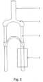
Die Idee unserer Erfindung ist ein Federgabelsystem, in dem nicht nur eine mit Gas befüllte Positiv-Druck-Kammer zum Einsatz kommt, sondern ein System, in welchem mehrere positiv Druckkammern mit spezifisch angepassten Eigenschaften speziell miteinander gekoppelt werden.
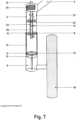
Zentral ist dabei, dass die nach außen wirkenden Kräfte der Kammern sich unterscheiden. Die Kammern sind über bewegliche Dichtungen voneinander abgetrennt. Somit unterscheiden sich entweder die Drücke in den Kammern oder die Fläche auf die der Druck wirkt. Wir haben uns auf die Realisierung unterschiedlicher Kräfte mit Druckdifferenzen konzentriert. Somit sind die Kammern mit verschiedenen Drücken befüllt und verfügen über räumliche Begrenzungen, damit sich der Druck nicht ausgleichen kann. Bei einer Erhöhung der Kraft kommen somit stufenweise immer mehr Kammer zum Einsatz. Zu Beginn wird die Kammer mit dem niedrigsten Druck komprimiert, bis ihr Druck dieser Kammer sich auf den Druck der Kammer mit dem nächsthöheren Wert erhöht hat. Die zweite Kammer schaltet sich quasi zu sodass bei weiterer Druckerhöhung beide Kammern gleichzeitig komprimiert werden. Diese Zuschaltung kann mit einer beliebigen Anzahl von Druckkammern erfolgen.
Dies hat zur Folge das der unerwünschte Teil der hyperbolischen Progression gestoppt wird und somit der lineare Verlauf sehr gut nähern lässt, was sich in unseren Forschungsergebnissen sowohl mathematisch/ physikalisch, sowie experimentell zeigen ließ.The idea of our invention is a suspension fork system in which not only a positive pressure chamber filled with gas is used, but a system in which several positive pressure chambers with specifically adapted properties are specifically coupled to one another.
What is central is that the outward forces of the chambers differ. The chambers are separated from each other by movable seals. This means that either the pressures in the chambers or the area on which the pressure acts differ. We focused on realizing different forces with pressure differences. The chambers are therefore filled with different pressures and have spatial limitations so that the pressure cannot equalize. As the force increases, more and more chambers are gradually used. Initially, the chamber with the lowest pressure is compressed until its pressure in that chamber has increased to the pressure of the chamber with the next highest value. The second chamber switches on virtually closed so that if the pressure increases further, both chambers are compressed at the same time. This connection can be done with any number of pressure chambers.
The result of this is that the undesirable part of the hyperbolic progression is stopped and the linear course can therefore be approximated very well, which was shown in our research results both mathematically/physically and experimentally.
Bei der Kompression der Gabel bleibt das Standrohr an Ort und Stelle und somit auch der Kolben. Wenn nun der Holm in das Standrohr ein federt wird zuerst Kammer 1 komprimiert. Sobald sie denselben Druck wie Kammer 2 erreicht fängt diese an sich ebenfalls zu komprimieren. Dasselbe geschieht mit Kammer 3.When the fork is compressed, the standpipe stays in place and so does the piston. When the spar now springs into the standpipe,
Für die Befüllung sind drei Möglichkeiten zweckmäßig. Die Erste ist in
Möglichkeit 2 ist eine spezifische Befüllung von außen (siehe
Möglichkeit 3 ist die einfachste/preisgünstigste und in
Glossar:Glossary:
- 11
- Lenkkopfsteering head
- 22
- GabellschaftFork shaft
- 33
- GabelkopfClevis
- 44
- GabelholmFork leg
- 55
- GabelstandbeinFork leg
- 66
- Befüll-VorrichtungFilling device
- 77
- LuftkammerAir chamber
- 88th
- Dichtungpoetry
- 99
- BegrenzungLimitation
- 1010
- MittelrohrCenter tube
- 1111
- KolbenPistons
- 1212
- Negativkammernegative chamber
- 1313
- Holmführungspar guide
- 1414
- StaubabstreiferDust wiper
- 1515
- DifferenzialdruckventilDifferential pressure valve
- 1616
- AutoventilCar valve
- 1717
- Befüll-KlappenFilling flaps
- 1818
- LaufradWheel
- 1919
- HinterradschwingeRear swing arm
- 2020
- HinterraddämpferRear shock
- 2121
- Kammer 1, positiv p0(Kammer 1) < p0(Kammer 2) < p0(Kammer 3)
Chamber 1, positive p0 (chamber 1) < p0 (chamber 2) < p0 (chamber 3) - 2222
- Kammer 2, positiv p0(Kammer 1) < p0(Kammer 2) < p0(Kammer 3)
Chamber 2, positive p0 (chamber 1) < p0 (chamber 2) < p0 (chamber 3) - 2323
- Kammer 3, positiv p0(Kammer 1) < p0(Kammer 2) < p0(Kammer 3)
Chamber 3, positive p0 (chamber 1) < p0 (chamber 2) < p0 (chamber 3) - 2424
- Inneres Befüll-RohrInner filling pipe
- 2525
- Äußeres Befüll-RohrExternal filling pipe
- 2626
- Rädchencogs
- 2727
- Kreisringförmige Dichtung mit Aussparung für das innere Befüll-Rohr [24] in der MitteCircular seal with recess for the inner filling pipe [24] in the middle
Claims (10)
Translated fromGermanPriority Applications (1)
| Application Number | Priority Date | Filing Date | Title |
|---|---|---|---|
| DE102022001109.3ADE102022001109A1 (en) | 2022-03-31 | 2022-03-31 | Air suspension fork with linearized spring characteristics thanks to a multi-chamber system |
Applications Claiming Priority (1)
| Application Number | Priority Date | Filing Date | Title |
|---|---|---|---|
| DE102022001109.3ADE102022001109A1 (en) | 2022-03-31 | 2022-03-31 | Air suspension fork with linearized spring characteristics thanks to a multi-chamber system |
Publications (1)
| Publication Number | Publication Date |
|---|---|
| DE102022001109A1true DE102022001109A1 (en) | 2023-10-05 |
Family
ID=88019155
Family Applications (1)
| Application Number | Title | Priority Date | Filing Date |
|---|---|---|---|
| DE102022001109.3AWithdrawnDE102022001109A1 (en) | 2022-03-31 | 2022-03-31 | Air suspension fork with linearized spring characteristics thanks to a multi-chamber system |
Country Status (1)
| Country | Link |
|---|---|
| DE (1) | DE102022001109A1 (en) |
Citations (5)
| Publication number | Priority date | Publication date | Assignee | Title |
|---|---|---|---|---|
| DE4226754A1 (en) | 1991-09-21 | 1993-03-25 | Bosch Gmbh Robert | SUSPENSION SYSTEM FOR VEHICLES |
| US20110204549A1 (en) | 2002-06-25 | 2011-08-25 | Fox Factory, Inc. | Gas spring curve control in an adjustable volume gas pressurized device |
| US20150233442A1 (en) | 2012-10-09 | 2015-08-20 | Kayaba Industry Co., Ltd. | Suspension device |
| US20150375593A1 (en) | 2008-03-19 | 2015-12-31 | Fox Factory, Inc. | Methods and apparatus for vehicle suspension having multiple gas volumes |
| US20160363184A1 (en) | 2015-06-11 | 2016-12-15 | Kyb Motorcycle Suspension Co., Ltd. | Damper |
- 2022
- 2022-03-31DEDE102022001109.3Apatent/DE102022001109A1/ennot_activeWithdrawn
Patent Citations (5)
| Publication number | Priority date | Publication date | Assignee | Title |
|---|---|---|---|---|
| DE4226754A1 (en) | 1991-09-21 | 1993-03-25 | Bosch Gmbh Robert | SUSPENSION SYSTEM FOR VEHICLES |
| US20110204549A1 (en) | 2002-06-25 | 2011-08-25 | Fox Factory, Inc. | Gas spring curve control in an adjustable volume gas pressurized device |
| US20150375593A1 (en) | 2008-03-19 | 2015-12-31 | Fox Factory, Inc. | Methods and apparatus for vehicle suspension having multiple gas volumes |
| US20150233442A1 (en) | 2012-10-09 | 2015-08-20 | Kayaba Industry Co., Ltd. | Suspension device |
| US20160363184A1 (en) | 2015-06-11 | 2016-12-15 | Kyb Motorcycle Suspension Co., Ltd. | Damper |
Similar Documents
| Publication | Publication Date | Title |
|---|---|---|
| DE3237579C2 (en) | ||
| EP3403910B1 (en) | Ram drive, in particular for a motor vehicle | |
| DE112010000707B4 (en) | Three-tube shock absorber with a shortened center tube | |
| DE102009023249B4 (en) | bicycle suspension system | |
| DE102010025697B4 (en) | Bicycle assembly with rear shock absorber | |
| DE602004006018T2 (en) | ADJUSTABLE GAS SPRING MOUNTING SYSTEM | |
| DE4017924A1 (en) | FRONT WHEEL FORK FOR BICYCLES | |
| DE102009022361A1 (en) | Bicycle suspension system | |
| DE102010025694A1 (en) | Bicycle assembly with reinforcement | |
| DE60306522T2 (en) | SUSPENSION SYSTEM FOR A VEHICLE | |
| DE10028114A1 (en) | Vibration damper | |
| DE102010025698A1 (en) | Bicycle shock absorber with extension arms | |
| DE112008001712T5 (en) | Bicycle spring assembly | |
| DE20022708U1 (en) | bicycle | |
| DE10121918B4 (en) | Spring damper system with resilient stop | |
| EP3412928B1 (en) | Shock absorbing device, in particular for a motor vehicle | |
| DE102014106723A1 (en) | Damper assembly with monotube and dynamic compression valve and vehicle with the same | |
| DE4123643A1 (en) | Bicycle with sprung wheels - has each damper connected to its pressure accumulator via manually-operated valve | |
| DE112013004595T5 (en) | suspension device | |
| DE112004001835T5 (en) | Design for an adjacent impact part of a shock absorber | |
| DE20005224U1 (en) | bicycle | |
| DE102004059764B4 (en) | Air spring and damper unit | |
| DE4429562A1 (en) | Hydraulic suspension unit for bicycle | |
| DE102022001109A1 (en) | Air suspension fork with linearized spring characteristics thanks to a multi-chamber system | |
| EP0994014A1 (en) | Hydraulic damping arrangement for the front and/or rear wheel of a two wheeled vehicle |
Legal Events
| Date | Code | Title | Description |
|---|---|---|---|
| R138 | Derivation of utility model | Ref document number:202022003176 Country of ref document:DE | |
| R012 | Request for examination validly filed | ||
| R118 | Application deemed withdrawn due to claim for domestic priority | ||
| R409 | Internal rectification of the legal status completed | ||
| R016 | Response to examination communication | ||
| R119 | Application deemed withdrawn, or ip right lapsed, due to non-payment of renewal fee |