DE102022000645A1 - Fiber molding, method for producing the same and use - Google Patents
Fiber molding, method for producing the same and useDownload PDFInfo
- Publication number
- DE102022000645A1 DE102022000645A1DE102022000645.6ADE102022000645ADE102022000645A1DE 102022000645 A1DE102022000645 A1DE 102022000645A1DE 102022000645 ADE102022000645 ADE 102022000645ADE 102022000645 A1DE102022000645 A1DE 102022000645A1
- Authority
- DE
- Germany
- Prior art keywords
- fiber
- mold
- paper structure
- electrically conductive
- section
- Prior art date
- Legal status (The legal status is an assumption and is not a legal conclusion. Google has not performed a legal analysis and makes no representation as to the accuracy of the status listed.)
- Withdrawn
Links
Images

Classifications
- H—ELECTRICITY
- H05—ELECTRIC TECHNIQUES NOT OTHERWISE PROVIDED FOR
- H05B—ELECTRIC HEATING; ELECTRIC LIGHT SOURCES NOT OTHERWISE PROVIDED FOR; CIRCUIT ARRANGEMENTS FOR ELECTRIC LIGHT SOURCES, IN GENERAL
- H05B3/00—Ohmic-resistance heating
- H05B3/20—Heating elements having extended surface area substantially in a two-dimensional plane, e.g. plate-heater
- H05B3/34—Heating elements having extended surface area substantially in a two-dimensional plane, e.g. plate-heater flexible, e.g. heating nets or webs
- H—ELECTRICITY
- H05—ELECTRIC TECHNIQUES NOT OTHERWISE PROVIDED FOR
- H05B—ELECTRIC HEATING; ELECTRIC LIGHT SOURCES NOT OTHERWISE PROVIDED FOR; CIRCUIT ARRANGEMENTS FOR ELECTRIC LIGHT SOURCES, IN GENERAL
- H05B2203/00—Aspects relating to Ohmic resistive heating covered by group H05B3/00
- H05B2203/011—Heaters using laterally extending conductive material as connecting means
- H—ELECTRICITY
- H05—ELECTRIC TECHNIQUES NOT OTHERWISE PROVIDED FOR
- H05B—ELECTRIC HEATING; ELECTRIC LIGHT SOURCES NOT OTHERWISE PROVIDED FOR; CIRCUIT ARRANGEMENTS FOR ELECTRIC LIGHT SOURCES, IN GENERAL
- H05B2203/00—Aspects relating to Ohmic resistive heating covered by group H05B3/00
- H05B2203/017—Manufacturing methods or apparatus for heaters
Landscapes
- Paper (AREA)
Abstract
Translated fromGermanDescription
Translated fromGermanDie Erfindung betrifft ein Faserformteil mit einem elektrisch leitenden Papiergefüge, wobei das Papiergefüge zumindest zwei sich entlang des Papiergefüges erstreckende Leiterbahnen aufweist und die Leiterbahnen jeweils mit einer für die Kontaktierung mit einer Stromquelle geeigneten elektrischen Leitung verbunden sind. Die Erfindung betrifft des Weiteren ein Verfahren zum Herstellen des Faserformteils und eine Verwendung.The invention relates to a molded fiber part with an electrically conductive paper structure, wherein the paper structure has at least two conductor tracks extending along the paper structure and the conductor tracks are each connected to an electrical line suitable for contacting a power source. The invention also relates to a method for producing the molded fiber part and a use.
Die gleichmäßige, großflächige Beheizung bestimmter Komponenten ist in vielen Bereichen vorteilhaft. So ist es hinsichtlich der kalten Wände in einem Flugzeug oder einem Kraftfahrzeug mit eventueller Wohnungseinrichtung zweckmäßig, über ein Gebläse Heizenergie in das System einzubringen, um auf diese Weise ein angenehmes Raumklima zu erzeugen. Die Einbringung von Heizenergie erfolgt beispielsweise in Kraftfahrzeugen mit eventueller Wohnungseinrichtung üblicherweise über Rohrsysteme, die elektrisch oder mit fossilen Brennstoffen betrieben werden, einen hohen Installationsaufwand erfordern und mit entsprechend hohen Kosten eingesetzt werden. Eine großflächige Beheizung ist schwer zu bewerkstelligen und die Tauwasserbildung kann nicht völlig vermieden werden.The uniform, large-area heating of certain components is advantageous in many areas. With regard to the cold walls in an airplane or a motor vehicle with possible home furnishings, it is advisable to introduce heating energy into the system via a blower in order to create a pleasant room climate in this way. The introduction of heating energy occurs, for example, in motor vehicles with possible home furnishings, usually via pipe systems that are operated electrically or with fossil fuels, require a high level of installation effort and are used at correspondingly high costs. It is difficult to heat large areas and the formation of condensation cannot be completely avoided.
Demgegenüber sind beheizte Flächen eine hinsichtlich des Wärmeeintrags schnelle und meist energiesparendere Alternative. Zudem tragen die beheizten Flächen innerhalb eines Kraftfahrzeugs mit eventueller Wohnungseinrichtung dazu bei, Kondenswasser zu vermeiden. Heizbare Papiere oder papierähnliche Materialien sind hierfür besonders geeignet, u.a. aufgrund der verwendeten Bordspannung. Es ist bekannt, Papier über die Einbringung leitfähiger Partikel, Fasern oder Beschichtungen im Zuge der Papierherstellung leitfähig zu machen, siehe z.B. die Schriften
Insbesondere für die Bereitstellung einer Flächenheizung eignet sich leitfähiges Papier hervorragend, weil es imprägnierbar ist und verhältnismäßig leicht in einen dekorativen, plattenförmigen Verbundkörper eingebracht werden kann. Gedruckte, beschichtete oder bedampfte Leiterbahnen sind im Falle einer Beheizung mit leitfähigem Papier besonders vorteilhaft, weil sie beim Imprägnieren keine große Barriere darstellen und im fertiggestellten Verbundkörper nicht mehr zu sehen sind. Eine Herausforderung besteht darin, die im dekorativen, plattenförmigen Verbundkörper eingebrachten Leiterbahnen wieder freizulegen und mit für die Kontaktierung mit einer Stromquelle geeigneten elektrischen Leitungen zu verbinden.Conductive paper is particularly suitable for providing surface heating because it can be impregnated and can be incorporated relatively easily into a decorative, panel-shaped composite body. Printed, coated or vapour-deposited conductor tracks are particularly advantageous in the case of heating with conductive paper because they do not represent a major barrier during impregnation and can no longer be seen in the finished composite body. One challenge is to uncover the conductor tracks introduced into the decorative, plate-shaped composite body and to connect them to electrical lines suitable for contacting a power source.
Der vorliegenden Erfindung liegt die Aufgabe zugrunde, die Nachteile des Standes der Technik zu überwinden und einen verbesserten Verbundkörper sowie ein verbessertes Verfahren zum Herstellen des Verbundkörpers bereitzustellen. Der Verbundkörper sollte insbesondere über eine Zusatzfunktion, vorzugsweise eine Heizbarkeit, verfügen.The object of the present invention is to overcome the disadvantages of the prior art and to provide an improved composite body and an improved method for producing the composite body. In particular, the composite body should have an additional function, preferably heatability.
Die Aufgabe wird durch die in den unabhängigen Ansprüchen definierten Merkmalskombinationen gelöst. Weiterbildungen der Erfindung sind Gegenstand der abhängigen Ansprüche.The object is achieved by the combinations of features defined in the independent claims. Developments of the invention are the subject matter of the dependent claims.
Zusammenfassung der ErfindungSummary of the Invention
- 1. (Erster Aspekt der Erfindung) Faserformteil (14), umfassend ein elektrisch leitendes Papiergefüge (2) mit einer oberen Hauptfläche und einer unteren Hauptfläche, wobei das elektrisch leitende Papiergefüge (2) zumindest zwei sich entlang des Papiergefüges (2) erstreckende Leiterbahnen (3) aufweist und die Leiterbahnen (3) jeweils mit einer für die Kontaktierung mit einer Stromquelle geeigneten elektrischen Leitung (4) verbunden sind, wobei die obere Hauptfläche des elektrisch leitenden Papiergefüges (2) einen oberen Faserformteilabschnitt (13) aufweist und/oder die untere Hauptfläche des elektrisch leitenden Papiergefüges (2) einen unteren Faserformteilabschnitt (13) aufweist, um auf diese Weise einen Verbundkörper zu bilden, wobei der Faserformteilabschnitt (13), gegebenenfalls sowohl der obere als auch der untere Faserformteilabschnitt (13), auf mit einem beigemischten Bindemittel verbundenen Matrixfasern basiert.1. (First aspect of the invention) fiber molding (14), comprising an electrically conductive paper structure (2) having an upper main surface and a lower main surface, wherein the electrically conductive paper structure (2) has at least two conductor tracks (2) extending along the paper structure (2). 3) and the conductor tracks (3) are each connected to an electrical line (4) suitable for contacting a power source, the upper main surface of the electrically conductive paper structure (2) having an upper molded fiber section (13) and/or the lower main surface of the electrically conductive paper structure (2) has a lower molded fiber section (13) so as to form a composite body, the molded fiber section (13), optionally both the upper and lower molded fiber section (13), being coated with an admixed binder connected matrix fibers is based.
- 2. (Bevorzugte Ausgestaltung) Faserformteil (14) nach Klausel 1, wobei die obere Hauptfläche des elektrisch leitenden Papiergefüges (2) einen oberen Faserformteilabschnitt (13) aufweist und die untere Hauptfläche des elektrisch leitenden Papiergefüges (2) einen unteren Faserformteilabschnitt (13) aufweist, sodass ein in das Faserformteil (14) eingebettetes elektrisch leitendes Papiergefüge (2) vorliegt, wobei sowohl der obere als auch der untere Faserformteilabschnitt (13) jeweils auf mit einem beigemischten Bindemittel verbundenen Matrixfasern basieren.2. (Preferred embodiment) The fibrous molding (14) according to
clause 1, wherein the upper major surface of the electrically conductive paper structure (2) has an upper fibrous molding section (13) and the lower major surface of the electrically conductive paper structure (2) has a lower fibrous molding section (13). , so that an electrically conductive paper structure (2) embedded in the molded fiber part (14) is present, both the upper and the lower molded fiber part section (13) each being based on matrix fibers bonded with an admixed binder. - 3. (Bevorzugte Ausgestaltung) Faserformteil (14) nach Klausel 1 oder 2, wobei die für die Kontaktierung mit einer Stromquelle geeigneten elektrischen Leitungen (4) jeweils auf eine isolierende Umhüllung aufweisenden metallischen elektrischen Leitern in Form von Drähten, Litzen, Bändern oder Schienen basieren, wobei die für die Kontaktierung mit einer Stromquelle geeigneten elektrischen Leitungen (4) vorzugsweise jeweils in Form eines Kabels vorliegen.3. (Preferred embodiment) Fiber molding (14) according to
clause - 4. (Bevorzugte Ausgestaltung) Faserformteil (14) nach einer der Klauseln 1 bis 3, wobei die Matrixfasern des Faserformteilabschnitts (13), gegebenenfalls sowohl des oberen als auch des unteren Faserformteilabschnitts (13), von der Gruppe bestehend aus Viskose, Basalt, Silikat, Glas oder einem Gemisch der vorstehend genannten Elemente gewählt sind und das Bindemittel des Faserformteilabschnitts (13), gegebenenfalls sowohl des oberen als auch des unteren Faserformteilabschnitts (13), von der Gruppe bestehend aus Bindefasern und Bindepulvern gewählt ist und vorzugsweise von der Gruppe bestehend aus Polyesterfasern, Copolyesterfasern, Polyethylenpulver, Acryllackpulver oder einem Gemisch zweier oder mehrerer der vorstehend genannten Elemente gewählt ist.4. (Preferred embodiment) fiber molding (14) according to one of
clauses 1 to 3, wherein the matrix fibers of the fiber molding section (13), optionally both the upper and the lower fiber molding section (13), from the group consisting of viscose, basalt, silicate , glass or a mixture of the above elements are selected and the binder of the fiber molding section (13), optionally both the upper and the lower fiber molding section (13), is selected from the group consisting of binding fibers and binding powders and preferably from the group consisting of polyester fibres, copolyester fibres, polyethylene powder, acrylic paint powder or a mixture of two or more of the above elements. - 5. (Bevorzugte Ausgestaltung) Faserformteil (14) nach einer der Klauseln 1 bis 4, wobei der Faserformteilabschnitt (13), gegebenenfalls sowohl der obere als auch der untere Faserformteilabschnitt (13), zusätzlich Granulat aufweist, das der Steuerung der Brennbarkeit, Wärmeleitfähigkeit, Isolierfähigkeit, Wasserabweisbarkeit und/oder Ölabweisbarkeit dient und vorzugsweise von der Gruppe bestehend aus Polystyrol, Kieselsäure, Aerogel, insbesondere Silikat-Aerogel, oder einem Gemisch zweier oder mehrerer der vorstehend genannten Elemente gewählt ist.5. (Preferred embodiment) fiber molded part (14) according to one of
clauses 1 to 4, wherein the fiber molded part section (13), optionally both the upper and the lower fiber molded part section (13), additionally has granules that control the combustibility, thermal conductivity, isolating ability, water repellency and/or oil repellency and is preferably selected from the group consisting of polystyrene, silicic acid, airgel, in particular silicate airgel, or a mixture of two or more of the above-mentioned elements. - 6. (Bevorzugte Ausgestaltung) Faserformteil (14) nach einer der Klauseln 1 bis 5, wobei die zumindest zwei sich entlang des Papiergefüges (2) erstreckenden Leiterbahnen (3) in Form von Metallstreifen oder Metallschienen vorliegen. Gemäß einer bevorzugten Variante werden die Metallstreifen durch Aufdampfen, Aufsprühen, Aufdrucken oder Abscheiden eines leitfähigen metallischen Materials auf dem Papiergefüge hergestellt.6. (Preferred embodiment) fiber molded part (14) according to one of
clauses 1 to 5, wherein the at least two conductor tracks (3) extending along the paper structure (2) are present in the form of metal strips or metal rails. According to a preferred variant, the metal strips are produced by vapor-depositing, spraying, printing or depositing a conductive metallic material on the paper structure. - 7. (Bevorzugte Ausgestaltung) Faserformteil (14) nach einer der Klauseln 1 bis 6, wobei die Verbindung der Leiterbahnen (3) mit den für die Kontaktierung mit einer Stromquelle geeigneten elektrischen Leitungen (4) jeweils mittels eines Steckverbinders, eines Klemmverbinders, einer elektrisch leitfähigen Klebeverbindung oder mittels einer Schraube in Verbindung mit einem Kabelschuh erfolgt.7. (Preferred embodiment) molded fiber part (14) according to one of
clauses 1 to 6, wherein the connection of the conductor tracks (3) to the electrical lines (4) suitable for contacting a power source is in each case by means of a plug connector, a clamp connector, an electrical conductive adhesive connection or by means of a screw in connection with a cable lug. - 8. (Bevorzugte Ausgestaltung) Faserformteil (14) nach einer der Klauseln 1 bis 7, wobei das elektrisch leitende Papiergefüge (2) auf cellulosehaltigen Faserstoffen und elektrisch leitfähigen Fasern basiert.8. (Preferred embodiment) Fiber molding (14) according to one of
clauses 1 to 7, wherein the electrically conductive paper structure (2) is based on cellulose-containing fibrous materials and electrically conductive fibers. - 9. (Zweiter Aspekt der Erfindung) Verwendung des Faserformteils (14) nach einer der Klauseln 1 bis 8 als Heizelement, als Element für die elektromagnetische Abschirmung, als Element zur Versorgung anderer elektrischer Verbraucher, als Element für die Ableitung elektrostatischer Ladungen oder als Element für die Signalweiterleitung bzw. Signaldetektion.9. (Second aspect of the invention) Use of the fiber molding (14) according to any one of
clauses 1 to 8 as a heating element, an electromagnetic shielding element, an element for supplying other electrical consumers, an element for dissipating electrostatic charges or an element for signal transmission or signal detection. - 10. (Dritter Aspekt der Erfindung) Verfahren zum Herstellen des Faserformteils (14) nach einer der Klauseln 1 bis 8, umfassend
- - das Bereitstellen eines Ausgangsmaterials (1), umfassend ein elektrisch leitendes Papiergefüge (2) mit einer oberen Hauptfläche und einer unteren Hauptfläche, wobei das elektrisch leitende Papiergefüge (2) zumindest zwei sich entlang des Papiergefüges (2) erstreckende Leiterbahnen (3) aufweist und die Leiterbahnen (3) jeweils mit einer für die Kontaktierung mit einer Stromquelle geeigneten elektrischen Leitung (4) verbunden sind;
- - das Einbringen des Ausgangsmaterials (1) in eine Form, umfassend eine Unterform (10) für das Erzeugen eines unteren Faserformteilabschnitts (13) und/oder eine Oberform (11) für das Erzeugen eines oberen Faserformteilabschnitts (13), wobei die Unterform (10) und/oder die Oberform (11) Löcher zum Durchströmen von Luft aufweisen und die Unterform (10) und/ oder die Oberform (11) Öffnungen für das Hindurchführen der elektrischen Leitungen (4) aufweisen;
- - das Einblasen von Matrixfasern und Bindemittel mittels eines Luftstroms in den Innenraum der geschlossenen Form;
- - das Anlagern von Matrixfasern an den Innenseiten der Unterform (10) und/oder der Oberform (11) bis die Form gefüllt ist;
- - das Verbinden der Matrixfasern mittels des beigemischten Bindemittels, wodurch sich der untere Faserformteilabschnitt (13) und/oder der obere Faserformteilabschnitt (13) verfestigt.
clauses 1 to 8, comprising- - the provision of a starting material (1), comprising an electrically conductive paper structure (2) with an upper main surface and a lower main surface, the electrically conductive paper structure (2) having at least two conductor tracks (3) extending along the paper structure (2) and the conductor tracks (3) are each connected to an electrical line (4) suitable for contacting a power source;
- - the introduction of the starting material (1) into a mold comprising a lower mold (10) for producing a lower fiber molded part section (13) and/or an upper mold (11) for producing an upper fiber molded part section (13), wherein the lower mold (10 ) and/or the upper mold (11) have holes for air to flow through and the lower mold (10) and/or the upper mold (11) have openings for the electrical lines (4) to pass through;
- - blowing matrix fibers and binder into the interior of the closed mold by means of an air stream;
- - The accumulation of matrix fibers on the insides of the lower mold (10) and/or the upper mold (11) until the mold is filled;
- - the joining of the matrix fibers by means of the admixed binder, whereby the lower molded fiber section (13) and/or the upper molded fiber section (13) solidifies.
- 11. (Bevorzugte Ausgestaltung) Verfahren nach Klausel 10 mit Rückbezug auf Klausel 2 oder einer der auf Klausel 2 rückbezogenen Klauseln 3 bis 8, umfassend
- - das Bereitstellen eines Ausgangsmaterials (1), umfassend ein elektrisch leitendes Papiergefüge (2) mit einer oberen Hauptfläche und einer unteren Hauptfläche, wobei das elektrisch leitende Papiergefüge (2) zumindest zwei sich entlang des Papiergefüges (2) erstreckende Leiterbahnen (3) aufweist und die Leiterbahnen (3) jeweils mit einer für die Kontaktierung mit einer Stromquelle geeigneten elektrischen Leitung (4) verbunden sind;
- - das Einbringen des Ausgangsmaterials (1) in eine Form, umfassend eine Unterform (10) für das Erzeugen eines unteren Faserformteilabschnitts (13) und eine Oberform (11) für das Erzeugen eines oberen Faserformteilabschnitts (13), wobei die Unterform (10) und/oder die Oberform (11) Löcher zum Durchströmen von Luft aufweisen und die Unterform (10) und/oder die Oberform (11) Öffnungen für das Hindurchführen der elektrischen Leitungen (4) aufweisen;
- - das Einblasen von Matrixfasern und Bindemittel mittels eines Luftstroms in den Innenraum der geschlossenen Form;
- - das Anlagern von Matrixfasern an den Innenseiten der Unterform (10) und der Oberform (11) bis die Form gefüllt ist;
- - das Verbinden der Matrixfasern mittels des beigemischten Bindemittels, wodurch sich sowohl der untere Faserformteilabschnitt (13) als auch der obere Faserformteilabschnitt (13) verfestigen.
clause 10 with reference back toclause 2 or one ofclauses 3 to 8 which refer back toclause 2, comprising- - providing a starting material (1) comprising an electrically conductive paper structure (2) having an upper major surface and a lower major surface, the electrically conductive paper structure (2) having at least two has conductor tracks (3) extending along the paper structure (2), and the conductor tracks (3) are each connected to an electrical line (4) suitable for contacting a power source;
- - introducing the starting material (1) into a mold comprising a lower mold (10) for producing a lower fiber molded part section (13) and an upper mold (11) for producing an upper fiber molded part section (13), the lower mold (10) and /or the upper mold (11) has holes for air to flow through and the lower mold (10) and/or the upper mold (11) has openings for the electrical lines (4) to pass through;
- - blowing matrix fibers and binder into the interior of the closed mold by means of an air stream;
- - The accumulation of matrix fibers on the insides of the lower mold (10) and the upper mold (11) until the mold is filled;
- - connecting the matrix fibers by means of the admixed binder, as a result of which both the lower molded fiber section (13) and the upper molded fiber section (13) solidify.
Ausführliche Beschreibung der bevorzugten AusführungsformenDetailed Description of Preferred Embodiments
Die vorliegende Erfindung ist auf dem technischen Gebiet elektrisch leitfähiger Papiergefüge angesiedelt, siehe z.B. die
Das erfindungsgemäße Faserformteil umfasst vorzugsweise ein in das Faserformteil eingebettetes elektrisch leitendes Papiergefüge mit einer oberen Hauptfläche und einer unteren Hauptfläche, wobei das elektrisch leitende Papiergefüge zumindest zwei sich entlang des Papiergefüges erstreckende Leiterbahnen aufweist und die Leiterbahnen jeweils mit einer für die Kontaktierung mit einer Stromquelle geeigneten elektrischen Leitung verbunden sind, wobei die obere Hauptfläche des elektrisch leitenden Papiergefüges einen oberen Faserformteilabschnitt aufweist und die untere Hauptfläche des elektrisch leitenden Papiergefüges einen unteren Faserformteilabschnitt aufweist, um auf diese Weise einen Verbundkörper zu bilden, wobei sowohl der obere als auch der untere Faserformteilabschnitt jeweils auf mit einem beigemischten Bindemittel verbundenen Matrixfasern basieren.The fiber molding according to the invention preferably comprises an electrically conductive paper structure embedded in the fiber molding with an upper main surface and a lower main surface, the electrically conductive paper structure having at least two conductor tracks extending along the paper structure and the conductor tracks each having an electrical connection suitable for contacting a power source line, wherein the upper major surface of the electrically conductive paper structure has an upper molded fiber portion and the lower major surface of the electrically conductive paper structure has a lower molded fiber portion, thereby forming a composite body, each of the upper and lower molded fiber portions being respectively on with matrix fibers connected to an admixed binder.
Der vorliegenden Erfindung liegt die Erkenntnis zugrunde, dass der Aufwand des nachträglichen Kontaktierens eines Verbundkörpers, in dem ein mit Leiterbahnen versehenes elektrisch leitendes Papiergefüge eingebettet ist, d.h. das Verbinden des Papiergefüges mit für die Kontaktierung mit einer Stromquelle geeigneten elektrischen Leitungen, in vorteilhafter Weise verringert werden kann, indem ein mit Leiterbahnen versehenes elektrisch leitendes Papiergefüge zunächst mit für die Kontaktierung mit einer Stromquelle geeigneten elektrischen Leitungen verbunden und das so erhaltene Ausgangsmaterial in eine für die Erzeugung von dreidimensional ausgeprägten Faserformteilen aus Fasermaterial geeignete hohle Form eingebracht wird, gefolgt von einem Schritt des Einblasens von Fasern und Bindemittel durch eine Luftströmung in die gelochte Form, um auf diese Weise einen Verbundkörper zu erhalten, bei dem das Leiterbahnen und elektrische Leitungen aufweisende elektrisch leitende Papiergefüge an seiner Oberseite und an seiner Unterseite jeweils einen Faserformteilabschnitt aufweist. Die elektrischen Leitungen, insbesondere Kabel, sowie das gegenüber Diffusion offene Papier behindern den Prozess des Einblasens von Luft nicht. Die auf Grundlage der vorliegenden Erfindung erhaltenen technischen Vorteile sind insbesondere: die innige, sichere Verbindung der elektrischen Leitungen, insbesondere Kabel, mit dem elektrisch leitenden Papiergefüge; das Vermeiden einer nachträglichen, häufig aufwändigen Kontaktierung des Papiergefüges mit Kabeln und damit verbunden die Einsparung von Kosten und Arbeitszeit; das Gewinnen von Designfreiheit hinsichtlich das Anordnens der elektrischen Leitungen, insbesondere Kabel, im zu erzeugenden Produkt; das Produkt ist nach Beendigung des Einblasens von Luft, Fasermaterial und Bindemittel in die gelochte Form nach einem Öffnen der Form fertiggestellt und einsatzbereit; die Kontaktierung ist im Faserformteil integriert und somit nicht sichtbar, fühlbar und vor äußeren Einflüssen geschützt.The present invention is based on the finding that the effort involved in subsequently contacting a composite body in which an electrically conductive paper structure provided with conductor tracks is embedded, ie connecting the paper structure with electrical lines suitable for contacting a power source, is advantageously reduced by first connecting an electrically conductive paper structure provided with conductor tracks with electrical lines suitable for contacting a power source and introducing the starting material obtained in this way into a hollow mold suitable for the production of three-dimensionally shaped fiber moldings from fiber material, followed by a blowing step of fibers and binder by an air flow into the perforated mold, in order in this way to obtain a composite body in which the electrically conductive paper structure having conductor tracks and electrical lines has a fiber molding section on its upper side and on its lower side, respectively. The electrical lines, in particular cables, as well as the paper open to diffusion do not impede the process of blowing in air. The technical advantages obtained on the basis of the present invention are in particular: the intimate, secure connection of the electrical conductors ments, in particular cables, with the electrically conductive paper structure; the avoidance of a subsequent, often complex contacting of the paper structure with cables and the associated savings in costs and working time; gaining design freedom with regard to arranging the electrical lines, in particular cables, in the product to be produced; the product is finished and ready for use after completion of the injection of air, fiber material and binder into the perforated mold after opening the mold; the contact is integrated in the molded fiber part and is therefore not visible, tangible and protected from external influences.
Eine für die Erzeugung des erfindungsgemäßen Faserformteils geeignete Form ist im Stand der Technik bekannt, siehe z.B. die Schriften
Eine für die Erzeugung des erfindungsgemäßen Faserformteils geeignete Form kann bei Bedarf auf einer mehrteiligen Form basieren, die zusätzlich zu einer Oberform und einer Unterform noch weitere Formteilmaterialelemente aufweist, siehe z.B. die
Die Matrixfasern können z.B. auf Fasern aus Viskose, Basalt, Glas, Silikat und/oder auf Mineralfasern basieren. Als Bindemittel eignen sich z.B. Kunststofffasern, insbesondere Polypropylenfasern, Polyesterfasern und Copolyesterfasern, oder Phenolharz. Das Bindemittel kann des Weiteren in Form eines Bindepulvers vorliegen, insbesondere in Form eines PE-Pulvers, Acryllackpulvers oder ähnlichen Bindeharzen. Geeignete Matrixfasern und Bindemittel sind dem Fachmann bekannt, siehe z.B. die
Gemäß einer bevorzugten Variante für das Erzeugen das Faserformteils weist das Matrixfasermaterial/Bindemittel-Gemisch zusätzlich Granulat auf, das der Steuerung der Brennbarkeit, Wärmeleitfähigkeit, Isolierfähigkeit, Wasserabweisbarkeit und/oder Ölabweisbarkeit dient und vorzugsweise von der Gruppe bestehend aus Polystyrol, Kieselsäure, Aerogel, insbesondere Silikat-Aerogel, oder einem Gemisch zweier oder mehrerer der vorstehend genannten Elemente gewählt ist. Geeignetes Granulat ist dem Fachmann bekannt, siehe z.B. die
Die Maßnahme des Bereitstellens eines mit Leiterbahnen versehenen, elektrisch leitenden Papiergefüges ist dem Fachmann bekannt, siehe z.B. die
Das elektrisch leitende Papiergefüge kann zur Steuerung der gewünschten Eigenschaften mit zusätzlichen Armierungsfasern versehen werden. Zusätzlich ist eine Oberflächenleimung oder eine Oberflächenimprägnierung möglich.The electrically conductive paper structure can be provided with additional reinforcing fibers to control the desired properties. In addition, surface sizing or surface impregnation is possible.
Mit Bezug auf die zumindest zwei sich entlang des elektrisch leitenden Papiergefüges erstreckenden Leiterbahnen sind unterschiedliche Ausführungen denkbar. Gemäß einer bevorzugten Variante werden z.B. Metallstreifen durch Aufdampfen, Aufsprühen, Aufdrucken oder Abscheiden eines leitfähigen metallischen Materials auf dem Papiergefüge hergestellt. Wichtig bei allen Ausführungen ist, dass ein Kontakt zu den im Papiergefüge befindlichen, leitfähigen Komponenten, insbesondere metallischen Fasern und/oder Kohlenstofffasern, sichergestellt ist. Im einfachsten Fall basiert die Leiterbahn auf einem metallischen Faden, z.B. aus gewalztem Metall, auf einem Metallband oder einem Metalldraht, wobei das Metall insbesondere von einem gut leitfähigen Metall wie etwa Silber, Kupfer, Gold, Aluminium, Wolfram, Eisen, Zink oder dergleichen oder einer Legierung eines oder mehrerer der vorstehend genannten Elemente gewählt ist. Des Weiteren ist aber auch die Verwendung eines metallisierten Fadens möglich, z.B. die Verwendung eines auf einer Kunststoffträgerfolie als Trägersubstrat basierenden, mit einem gut leitfähigen Metall wie etwa Silber, Kupfer, Gold, Aluminium, Wolfram, Eisen, Zink oder dergleichen metallisierten Fadens. Als Kunststoffträgerfolie kann insbesondere Polyethylenterephthalat (PET) verwendet werden. Des Weiteren kann als Leiterbahn eine metallisierte Folie oder ein Laminat aus Folien und gewalzten Metallfolien verwendet werden. Metallisierte Fäden können zur besseren Fixierung im elektrisch leitenden Papiergefüge zusätzlich, zumindest einseitig, mit einem Klebstoff ausgestattet sein, der mit Vorteil ein leitfähiger Klebstoff ist. Weiterhin ist es möglich, dass die jeweilige Leiterbahn auf dem Papier aufgebracht ist oder im elektrisch leitenden Papiergefüge eingebettet ist oder weitgehend im elektrisch leitenden Papiergefüge eingebracht ist und insbesondere im Bereich der Kontaktierungsstelle partiell freiliegt, wie es im Banknotenbereich bei sogenannten Fensterfäden der Fall ist. Der Begriff Leiterbahn ist nicht zwangsläufig auf eine alleinige Ausgestaltung als (eher schmaler) Faden beschränkt, der z.B. eine Breite von 2 mm oder weniger aufweist, sondern Ausgestaltungen wie (eher breite) Streifen oder Bänder sind ebenfalls denkbar, die z.B. eine Breite von 4 mm bis 20 mm, oder sogar eine Breite bis 30 mm, aufweisen. Grundsätzlich ist es ebenfalls denkbar, dass als Leiterbahn ein einfacher leitfähiger Metalldraht oder ein Metallgeflecht verwendet wird. Auch Ausführungsvarianten wie z.B. Flachlitzen, Zopfgeflechte, Gestricke, Lahnbänder und dergleichen sind möglich. Des Weiteren kann die jeweilige Leiterbahnen drucktechnisch hergestellt werden, zum Beispiel mittels eines Siebdruckverfahrens. Als leifähige Lacke können z.B. wässrige Siebdruckfarben auf Basis von Rußpartikeln, Silberpartikeln oder anderen die Leitfähigkeit herstellenden Partikeln verwendet werden.Different designs are conceivable with regard to the at least two conductor tracks extending along the electrically conductive paper structure. According to a preferred variant, e.g. It is important in all versions that contact with the conductive components located in the paper structure, in particular metallic fibers and/or carbon fibers, is ensured. In the simplest case, the conductor track is based on a metallic thread, e.g. made of rolled metal, on a metal strip or a metal wire, with the metal being made in particular from a highly conductive metal such as silver, copper, gold, aluminium, tungsten, iron, zinc or the like or an alloy of one or more of the above elements. Furthermore, the use of a metallized thread is also possible, e.g. the use of a thread based on a plastic carrier film as the carrier substrate and metallized with a highly conductive metal such as silver, copper, gold, aluminum, tungsten, iron, zinc or the like. In particular, polyethylene terephthalate (PET) can be used as the plastic carrier film. Furthermore, a metallized foil or a laminate of foils and rolled metal foils can be used as the conductor track. For better fixation in the electrically conductive paper structure, metallized threads can additionally be equipped with an adhesive, at least on one side, which is advantageously a conductive adhesive. It is also possible that the respective conductor track is applied to the paper or is embedded in the electrically conductive paper structure or is largely introduced into the electrically conductive paper structure and is partially exposed in particular in the area of the contact point, as is the case with so-called window threads in the banknote area. The term conductor track is not necessarily limited to a single configuration as a (rather narrow) thread that has a width of 2 mm or less, for example, but configurations such as (rather wide) strips or bands are also conceivable, which have a width of 4 mm, for example up to 20 mm, or even a width up to 30 mm. In principle, it is also conceivable that a simple conductive metal wire or a metal mesh is used as the conductor track. Variants such as flat braids, braids, knitted fabrics, tinsel tapes and the like are also possible. Furthermore, the respective conductor tracks can be produced by printing, for example by means of a screen printing process. For example, aqueous screen printing inks based on carbon black particles, silver particles or other particles that produce conductivity can be used as conductive paints.
Die für die Kontaktierung mit einer Stromquelle geeigneten elektrischen Leitungen basieren z.B. jeweils auf eine isolierende Umhüllung aufweisenden metallischen elektrischen Leitern in Form von Drähten, Litzen, Bändern oder Schienen. Vorzugsweise liegen die für die Kontaktierung mit einer Stromquelle geeigneten elektrischen Leitungen jeweils in Form eines Kabels vor.The electrical lines suitable for making contact with a power source are based, for example, on metallic electrical conductors in the form of wires, strands, strips or rails each having an insulating sheath. The electrical lines suitable for contacting a power source are preferably each in the form of a cable.
Die Verbindung der Leiterbahnen mit den für die Kontaktierung mit einer Stromquelle geeigneten elektrischen Leitungen erfolgt z.B. jeweils mittels eines Steckverbinders, eines Klemmverbinders, einer elektrisch leitfähigen Klebeverbindung oder mittels einer Schraube in Verbindung mit einem Kabelschuh.The conductor tracks are connected to the electrical lines suitable for contacting a power source, for example by means of a plug connector, a clamp connector, an electrically conductive adhesive connection or a screw in conjunction with a cable lug.
Die vorliegende Erfindung umfasst des Weiteren eine Verwendung des Faserformteils als Heizelement, als Element für die elektromagnetische Abschirmung, als Element zur Versorgung anderer elektrischer Verbraucher, als Element für die Ableitung elektrostatischer Ladungen oder als Element für die Signalweiterleitung bzw. Signaldetektion.The present invention also includes using the fiber molding as a heating element, as an element for electromagnetic shielding, as an element for supplying other electrical consumers, as an element for dissipating electrostatic charges or as an element for signal transmission or signal detection.
Weitere Ausführungsbeispiele sowie Vorteile der Erfindung werden nachfolgend anhand der Figuren erläutert, bei deren Darstellung auf eine maßstabs- und proportionsgetreue Wiedergabe verzichtet wurde, um die Anschaulichkeit zu erhöhen.Further exemplary embodiments and advantages of the invention are explained below with reference to the figures, which are not shown to scale and proportions in order to improve clarity.
Es zeigen:
1 bis 5 ein Ausführungsbeispiel für das Herstellen des erfindungsgemäßen Faserformteils.
1 until5 an embodiment for the production of the fiber molded part according to the invention.
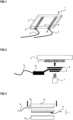
Die
Gemäß der
Die
Ausgehend von dem in der
Gemäß der
Die verschlossene Form ist in der
Die
ZITATE ENTHALTEN IN DER BESCHREIBUNGQUOTES INCLUDED IN DESCRIPTION
Diese Liste der vom Anmelder aufgeführten Dokumente wurde automatisiert erzeugt und ist ausschließlich zur besseren Information des Lesers aufgenommen. Die Liste ist nicht Bestandteil der deutschen Patent- bzw. Gebrauchsmusteranmeldung. Das DPMA übernimmt keinerlei Haftung für etwaige Fehler oder Auslassungen.This list of documents cited by the applicant was generated automatically and is included solely for the better information of the reader. The list is not part of the German patent or utility model application. The DPMA assumes no liability for any errors or omissions.
Zitierte PatentliteraturPatent Literature Cited
- US 4990755 A [0003]US4990755A [0003]
- JP H05135774 A [0003]JP H05135774 A [0003]
- EP 1063716 A2 [0003]EP 1063716 A2 [0003]
- WO 2020224800 A1 [0003, 0007, 0014]WO 2020224800 A1 [0003, 0007, 0014]
- WO 2004106042 A1 [0007, 0010, 0026]WO 2004106042 A1 [0007, 0010, 0026]
- WO 2014053505 A1 [0007, 0010]WO 2014053505 A1 [0007, 0010]
- EP 3351369 A1 [0007, 0010, 0012, 0013]EP 3351369 A1 [0007, 0010, 0012, 0013]
- EP 3772408 A1 [0007, 0010, 0011]EP 3772408 A1 [0007, 0010, 0011]
Claims (11)
Translated fromGermanPriority Applications (2)
| Application Number | Priority Date | Filing Date | Title |
|---|---|---|---|
| DE102022000645.6ADE102022000645A1 (en) | 2022-02-22 | 2022-02-22 | Fiber molding, method for producing the same and use |
| EP22020564.5AEP4231776A1 (en) | 2022-02-22 | 2022-11-16 | Moulded fibre part, method for producing the same and use |
Applications Claiming Priority (1)
| Application Number | Priority Date | Filing Date | Title |
|---|---|---|---|
| DE102022000645.6ADE102022000645A1 (en) | 2022-02-22 | 2022-02-22 | Fiber molding, method for producing the same and use |
Publications (1)
| Publication Number | Publication Date |
|---|---|
| DE102022000645A1true DE102022000645A1 (en) | 2023-08-24 |
Family
ID=84358937
Family Applications (1)
| Application Number | Title | Priority Date | Filing Date |
|---|---|---|---|
| DE102022000645.6AWithdrawnDE102022000645A1 (en) | 2022-02-22 | 2022-02-22 | Fiber molding, method for producing the same and use |
Country Status (2)
| Country | Link |
|---|---|
| EP (1) | EP4231776A1 (en) |
| DE (1) | DE102022000645A1 (en) |
Citations (8)
| Publication number | Priority date | Publication date | Assignee | Title |
|---|---|---|---|---|
| US4990755A (en) | 1988-12-06 | 1991-02-05 | Makoto Nishimura | Heatable sheet assembly |
| JPH05135774A (en) | 1991-11-14 | 1993-06-01 | Mitsubishi Rayon Co Ltd | Carbon fiber porous electrode |
| EP1063716A2 (en) | 1999-06-22 | 2000-12-27 | Johnson Matthey Public Limited Company | Carbon fibers containing non-woven fibre web for use as gas diffusion electrode substrate in fuel cells |
| WO2004106042A1 (en) | 2003-05-30 | 2004-12-09 | Fiber Engineering Gmbh | Method and device for producing three-dimensional molded parts and corresponding molded part |
| WO2014053505A1 (en) | 2012-10-05 | 2014-04-10 | Fiber Engineering Gmbh | Method and device for producing moulded parts made of fibre material |
| EP3351369A1 (en) | 2017-01-20 | 2018-07-25 | Fiber Engineering GmbH | Three-dimensional moulded fibrous part, device and method for building a three-dimensional moulded fibrous part |
| WO2020224800A1 (en) | 2019-05-09 | 2020-11-12 | Giesecke+Devrient Currency Technology Gmbh | Electrically conductive paper structure, method for manufacturing same and use |
| EP3772408A1 (en) | 2019-08-06 | 2021-02-10 | Fiber Engineering GmbH | Method and device for producing three-dimensional shaped parts |
Family Cites Families (8)
| Publication number | Priority date | Publication date | Assignee | Title |
|---|---|---|---|---|
| JPS522915Y2 (en)* | 1972-02-09 | 1977-01-22 | ||
| US4250397A (en)* | 1977-06-01 | 1981-02-10 | International Paper Company | Heating element and methods of manufacturing therefor |
| KR100337609B1 (en)* | 2000-08-26 | 2002-05-22 | 서영석 | Sheet heater of carbon-fiber paper containing ceramic materials |
| KR200446123Y1 (en)* | 2007-01-09 | 2009-09-28 | 이장훈 | The sheet type heating element |
| KR100909930B1 (en)* | 2007-11-23 | 2009-07-29 | 에스케이케미칼주식회사 | Planar heating element and its manufacturing method |
| DE102013101899A1 (en)* | 2013-02-26 | 2014-08-28 | Peter Helfer | Electrically conductive paper texture |
| CN204180300U (en)* | 2014-10-03 | 2015-02-25 | 北京中科联众科技股份有限公司 | The carbon fiber heating film that a kind of resistance is adjustable |
| WO2021209440A1 (en)* | 2020-04-15 | 2021-10-21 | Reso Oberflächentechnik Gmbh | Electrically conductive paper |
- 2022
- 2022-02-22DEDE102022000645.6Apatent/DE102022000645A1/ennot_activeWithdrawn
- 2022-11-16EPEP22020564.5Apatent/EP4231776A1/enactivePending
Patent Citations (8)
| Publication number | Priority date | Publication date | Assignee | Title |
|---|---|---|---|---|
| US4990755A (en) | 1988-12-06 | 1991-02-05 | Makoto Nishimura | Heatable sheet assembly |
| JPH05135774A (en) | 1991-11-14 | 1993-06-01 | Mitsubishi Rayon Co Ltd | Carbon fiber porous electrode |
| EP1063716A2 (en) | 1999-06-22 | 2000-12-27 | Johnson Matthey Public Limited Company | Carbon fibers containing non-woven fibre web for use as gas diffusion electrode substrate in fuel cells |
| WO2004106042A1 (en) | 2003-05-30 | 2004-12-09 | Fiber Engineering Gmbh | Method and device for producing three-dimensional molded parts and corresponding molded part |
| WO2014053505A1 (en) | 2012-10-05 | 2014-04-10 | Fiber Engineering Gmbh | Method and device for producing moulded parts made of fibre material |
| EP3351369A1 (en) | 2017-01-20 | 2018-07-25 | Fiber Engineering GmbH | Three-dimensional moulded fibrous part, device and method for building a three-dimensional moulded fibrous part |
| WO2020224800A1 (en) | 2019-05-09 | 2020-11-12 | Giesecke+Devrient Currency Technology Gmbh | Electrically conductive paper structure, method for manufacturing same and use |
| EP3772408A1 (en) | 2019-08-06 | 2021-02-10 | Fiber Engineering GmbH | Method and device for producing three-dimensional shaped parts |
Also Published As
| Publication number | Publication date |
|---|---|
| EP4231776A1 (en) | 2023-08-23 |
Similar Documents
| Publication | Publication Date | Title |
|---|---|---|
| EP2612546B1 (en) | Emf-shielded plastic organo-sheet hybrid structural component | |
| EP0611339A1 (en) | Formed body with agglomerated thermoplastic material and/or plastic foil material | |
| DE102017126461A1 (en) | Sound-absorbing textile with improved thermal insulation and method of making the same | |
| DE102012213314B4 (en) | Composite for shielding broadband electromagnetic waves and method of forming the composite | |
| EP3966388B1 (en) | Electrically conductive paper structure, method for producing the same and use | |
| DE4306143C2 (en) | Method for producing an injection molded plastic housing for a motor vehicle door lock | |
| DE10026714A1 (en) | Composite film, process for its production and its use | |
| WO2003070524A1 (en) | Method for creating a conductor track on a carrier component and corresponding carrier component | |
| DE102017129353A1 (en) | Polymer-based substrate and process for its preparation | |
| DE102022000645A1 (en) | Fiber molding, method for producing the same and use | |
| WO2002029939A1 (en) | Electric bus bar, the use thereof and a method for producing the same | |
| EP1028202B1 (en) | Heat and sound insulation element | |
| DE102004007875B3 (en) | Three-dimensionally shaped flat cable | |
| DE102010007108A1 (en) | On-board network for vehicle produced in mixed construction, comprises body, which is made partly of electrically non-conducting material, where components of on-board network are arranged on electrical non-conducting material of body | |
| DE10106410A1 (en) | Motor vehicle front panel made of thermoplastic resin | |
| WO2018130550A1 (en) | Vehicle component with foamed electrical conductive structure and manufacturing method for such a component | |
| EP1572500B1 (en) | Damping material and method for the production thereof | |
| EP3607564B1 (en) | Electric isolation tape, electrical high voltage machine and method for producing an electric isolation tape and an electric high voltage machine | |
| DE102020115627A1 (en) | PAINTED ELECTROLUMINESCENT VEHICLE FAIRING COMPONENTS | |
| DE19910274A1 (en) | Roof covering and process for its manufacture | |
| DE102023100236A1 (en) | Contacting an electrically conductive paper layer | |
| DE102009036785A1 (en) | Thermal insulation element and motor vehicle with a thermal insulation element | |
| EP2217769B3 (en) | Non-combustible absorber element for heat and/or sound damping and method for the production of said absorber element | |
| DE102022118724A1 (en) | Method for producing a wall heater, a heating wallpaper and a heating ink mixture and an inkjet printer with a heating ink | |
| DE102014106615A1 (en) | Interior trim element for arrangement and / or use and / or installation in the interior of a motor vehicle |
Legal Events
| Date | Code | Title | Description |
|---|---|---|---|
| R119 | Application deemed withdrawn, or ip right lapsed, due to non-payment of renewal fee |