DE102021214594A1 - Hand-held power tool assembly with torque socket assembly and method - Google Patents
Hand-held power tool assembly with torque socket assembly and methodDownload PDFInfo
- Publication number
- DE102021214594A1 DE102021214594A1DE102021214594.9ADE102021214594ADE102021214594A1DE 102021214594 A1DE102021214594 A1DE 102021214594A1DE 102021214594 ADE102021214594 ADE 102021214594ADE 102021214594 A1DE102021214594 A1DE 102021214594A1
- Authority
- DE
- Germany
- Prior art keywords
- torque
- socket device
- unit
- torque socket
- parameter
- Prior art date
- Legal status (The legal status is an assumption and is not a legal conclusion. Google has not performed a legal analysis and makes no representation as to the accuracy of the status listed.)
- Pending
Links
- 238000000034methodMethods0.000titleclaimsdescription55
- 238000004891communicationMethods0.000claimsabstractdescription70
- 230000008878couplingEffects0.000claimsabstractdescription30
- 238000010168coupling processMethods0.000claimsabstractdescription30
- 238000005859coupling reactionMethods0.000claimsabstractdescription30
- 238000011156evaluationMethods0.000claimsdescription36
- 230000003287optical effectEffects0.000claimsdescription26
- 230000008569processEffects0.000claimsdescription20
- 230000005540biological transmissionEffects0.000description12
- 230000007246mechanismEffects0.000description6
- 230000006870functionEffects0.000description3
- 230000001133accelerationEffects0.000description2
- 238000005299abrasionMethods0.000description1
- 230000008859changeEffects0.000description1
- 238000001514detection methodMethods0.000description1
- 230000007613environmental effectEffects0.000description1
- 230000005284excitationEffects0.000description1
- 239000007788liquidSubstances0.000description1
- 239000000463materialSubstances0.000description1
- 239000011159matrix materialSubstances0.000description1
- 238000012544monitoring processMethods0.000description1
- 239000003973paintSubstances0.000description1
Images


Classifications
- B—PERFORMING OPERATIONS; TRANSPORTING
- B25—HAND TOOLS; PORTABLE POWER-DRIVEN TOOLS; MANIPULATORS
- B25B—TOOLS OR BENCH DEVICES NOT OTHERWISE PROVIDED FOR, FOR FASTENING, CONNECTING, DISENGAGING OR HOLDING
- B25B13/00—Spanners; Wrenches
- B25B13/02—Spanners; Wrenches with rigid jaws
- B25B13/06—Spanners; Wrenches with rigid jaws of socket type
- B—PERFORMING OPERATIONS; TRANSPORTING
- B25—HAND TOOLS; PORTABLE POWER-DRIVEN TOOLS; MANIPULATORS
- B25B—TOOLS OR BENCH DEVICES NOT OTHERWISE PROVIDED FOR, FOR FASTENING, CONNECTING, DISENGAGING OR HOLDING
- B25B23/00—Details of, or accessories for, spanners, wrenches, screwdrivers
- B25B23/0007—Connections or joints between tool parts
- B25B23/0035—Connection means between socket or screwdriver bit and tool
- B—PERFORMING OPERATIONS; TRANSPORTING
- B25—HAND TOOLS; PORTABLE POWER-DRIVEN TOOLS; MANIPULATORS
- B25B—TOOLS OR BENCH DEVICES NOT OTHERWISE PROVIDED FOR, FOR FASTENING, CONNECTING, DISENGAGING OR HOLDING
- B25B23/00—Details of, or accessories for, spanners, wrenches, screwdrivers
- B25B23/14—Arrangement of torque limiters or torque indicators in wrenches or screwdrivers
- B25B23/141—Mechanical overload release couplings
- B—PERFORMING OPERATIONS; TRANSPORTING
- B25—HAND TOOLS; PORTABLE POWER-DRIVEN TOOLS; MANIPULATORS
- B25F—COMBINATION OR MULTI-PURPOSE TOOLS NOT OTHERWISE PROVIDED FOR; DETAILS OR COMPONENTS OF PORTABLE POWER-DRIVEN TOOLS NOT PARTICULARLY RELATED TO THE OPERATIONS PERFORMED AND NOT OTHERWISE PROVIDED FOR
- B25F5/00—Details or components of portable power-driven tools not particularly related to the operations performed and not otherwise provided for
Landscapes
- Engineering & Computer Science (AREA)
- Mechanical Engineering (AREA)
- Details Of Spanners, Wrenches, And Screw Drivers And Accessories (AREA)
Abstract
Translated fromGermanDescription
Translated fromGermanStand der TechnikState of the art
Es ist bereits eine Drehmomentstecknussvorrichtung mit einer Werkzeugaufnahme, einer Befestigungselementaufnahme und einer Drehmomentkupplung, über die die Werkzeugaufnahme und die Befestigungselementaufnahme miteinander gekoppelt sind, wobei die Drehmomentkupplung dazu vorgesehen ist, die Werkzeugaufnahme und die Befestigungselementaufnahme bei Erreichen eines Grenzdrehmoments zumindest teilweise voneinander zu entkoppeln, vorgeschlagen worden.A torque socket device with a tool holder, a fastener holder and a torque coupling, via which the tool holder and the fastener holder are coupled to one another, has already been proposed, with the torque coupling being provided to at least partially decouple the tool holder and the fastener holder from one another when a limit torque is reached .
Offenbarung der ErfindungDisclosure of Invention
Die Erfindung geht aus von einer Drehmomentstecknussvorrichtung mit einer Werkzeugaufnahme, einer Befestigungselementaufnahme und einer Drehmomentkupplung, über die die Werkzeugaufnahme und die Befestigungselementaufnahme miteinander gekoppelt sind, wobei die Drehmomentkupplung dazu vorgesehen ist, die Werkzeugaufnahme und die Befestigungselementaufnahme bei Erreichen eines Grenzdrehmoments zumindest teilweise voneinander zu entkoppeln.The invention is based on a torque socket device with a tool holder, a fastener holder and a torque coupling, via which the tool holder and the fastener holder are coupled to one another, the torque coupling being provided for at least partially decoupling the tool holder and the fastener holder from one another when a limit torque is reached.
Es wird vorgeschlagen, dass die Drehmomentstecknussvorrichtung eine Identifikationseinheit aufweist, die zumindest zu einer digitalen Kommunikation zumindest eines Drehmomentstecknussvorrichtungsparameters vorgesehen ist. Unter einer „Handwerkzeugmaschinenvorrichtung“ soll zumindest ein Teil einer Handwerkzeugmaschine, vorzugsweise die gesamte Handwerkzeugmaschine verstanden werden. Unter einer „Handwerkzeugmaschine“ soll in diesem Zusammenhang eine werkstückbearbeitende Maschine, vorteilhaft jedoch ein Akkuschrauber, eine Bohrmaschine, ein Bohr- und/oder Schlaghammer, ein elektrischer Schraubendreher, ein Schrauber und/oder ein Multifunktionswerkzeug verstanden werden. Die Handwerkzeugmaschine ist elektrisch angetrieben. Unter einer „Werkzeugaufnahme“ soll eine Aufnahme verstanden werden, die dazu vorgesehen ist, mit einer Handwerkzeugmaschine verbunden zu werden, um ein Drehmoment auf die Drehmomentstecknussvorrichtung zu übertragen. Die Werkzeugaufnahme ist als ein Kraft- und/oder Formschlusselement ausgebildet. Vorzugsweise weist die Werkzeugaufnahme einen Zapfen mit einer Außenkontur, vorzugsweise einem Außenvierkant auf. Unter einer „Befestigungselementaufnahme“ soll vorzugsweise eine Aufnahme für ein Werkzeug, wie beispielsweise für einen Bitaufsatz, oder einen Bohrer verstanden werden, in dem das Werkzeug form- und/oder kraftschlüssig angebunden werden kann. Die Befestigungselementaufnahme ist vorzugsweise von einem Formschlusselement ausgebildet. Die Befestigungselementaufnahme ist vorzugsweise von einem Aufnahmeloch mit einer Kontur gebildet. Vorzugsweise ist die Befestigungselementaufnahme von einem Aufnahmeloch mit einem Innensechskant gebildet. Grundsätzlich ist es auch denkbar, dass die Befestigungselementaufnahme eine andere Kontur aufweist, über die ein Werkzeug rotationsfest in der Befestigungselementaufnahme angeordnet werden kann. Unter einer „Drehmomentkupplung“ soll vorzugsweise eine Kupplung mit einer Eingangsseite und einer Ausgangsseite verstanden werden, die bis zu einem Grenzdrehmoment drehfest miteinander verbunden und bei Überschreitung eines wirkenden Drehmoments über das Grenzdrehmoment zueinander drehbar sind. Das Grenzdrehmoment kann dabei fest eingestellt und nicht veränderbar oder durch einen Benutzer veränderbar sein. Unter einem „Grenzdrehmoment“ soll vorzugsweise ein Drehmoment verstanden werden, das gerade noch von der Drehmomentkupplung, insbesondere zwischen der Eingangsseite und der Ausgangsseite der Drehmomentkupplung übertragen werden kann. Wirkt ein Drehmoment zwischen der Eingangsseite und der Ausgangsseite der Drehmomentkupplung, das größer ist als das Grenzdrehmoment, sind die Eingangsseite und die Ausgangsseite drehbar zueinander. Das Grenzdrehmoment ist vorzugsweise das die Drehmomentkupplung auslösende Drehmoment. An die Ausgangsseite der Drehmomentkupplung kann von der Eingangsseite aus maximal, vorzugsweise genau das eingestellte Grenzdrehmoment übertragen werden. Unter „zumindest teilweise voneinander entkoppeln“ soll vorzugsweise verstanden werden, dass die Eingangsseite und die Ausgangsseite der Drehmomentkupplung rotatorisch voneinander entkoppelt werden, sich also zueinander verdrehen können. Bei der teilweisen Entkopplung sind die Eingangsseite und die Ausgangsseite der Drehmomentkupplung vorzugsweise in einer Axialrichtung weiterhin zueinander fixiert. Unter einer „Identifikationseinheit“ soll vorzugsweise eine Einheit verstanden werden, die dazu vorgesehen ist, zumindest einen Parameter, insbesondere den Drehmomentstecknussvorrichtungsparameter digital auslesbar darzustellen oder auszugeben. Unter einer „digitalen Kommunikation vorgesehen“ soll vorzugsweise verstanden werden, dass ein digital auslesbares Signal bereitgestellt wird, oder ein Signal digital, beispielsweise in Form eines Funksignals ausgegeben wird, das digital erfasst und ausgewertet werden kann. Ein digital auslesbares Signal kann beispielsweise als ein optisches Signal ausgebildet sein, das beispielsweise von einer Kameraeinheit erfasst werden kann. Unter einem „Drehmomentstecknussvorrichtungsparameter“ soll vorzugsweise ein Parameter der Drehmomentenstecknuss verstanden werden, wie insbesondere ein Grenzdrehmoment der Drehmomentkupplung, eine Toleranz des Grenzdrehmoments, ein Parameter für den Antrieb, mit dem die Drehmomentstecknussvorrichtung angetrieben ist, oder andere Parameter, die eine Eigenschaft der Drehmomentenstecknuss wiedergeben.It is proposed that the torque socket device has an identification unit which is provided at least for digital communication of at least one torque socket device parameter. A “handheld power tool device” should be understood to mean at least part of a handheld power tool, preferably the entire handheld power tool. In this context, a “handheld power tool” should be understood to mean a machine that processes a workpiece, but advantageously a cordless screwdriver, a drill, a rotary and/or demolition hammer, an electric screwdriver, a screwdriver and/or a multifunction tool. The hand tool is electrically powered. A “tool holder” should be understood to mean a holder that is intended to be connected to a hand-held power tool in order to transmit torque to the torque socket device. The tool holder is designed as a force and/or form-fitting element. The tool holder preferably has a pin with an outer contour, preferably an outer square. A “fastening element receptacle” should preferably be understood to mean a receptacle for a tool, such as a bit attachment, or a drill, in which the tool can be connected in a form-fitting and/or non-positive manner. The fastening element receptacle is preferably formed by a form-fitting element. The fastener receptacle is preferably formed by a receiving hole with a contour. The fastening element receptacle is preferably formed by a receiving hole with a hexagon socket. In principle, it is also conceivable for the fastening element receptacle to have a different contour, via which a tool can be arranged in the fastening element receptacle in a rotationally fixed manner. A “torque clutch” should preferably be understood to mean a clutch with an input side and an output side, which are connected to one another in a torque-proof manner up to a limit torque and can be rotated relative to one another when an acting torque is exceeded above the limit torque. The limit torque can be permanently set and not changeable or can be changed by a user. A “limit torque” should preferably be understood to mean a torque that can just about be transmitted by the torque clutch, in particular between the input side and the output side of the torque clutch. If a torque that is greater than the limit torque acts between the input side and the output side of the torque coupling, the input side and the output side can be rotated in relation to one another. The limit torque is preferably the torque that triggers the torque clutch. The set limit torque can be transmitted from the input side to the output side of the torque clutch at most, preferably precisely. “At least partially decoupled from one another” should preferably be understood to mean that the input side and the output side of the torque clutch are rotationally decoupled from one another, that is, they can rotate relative to one another. With the partial decoupling, the input side and the output side of the torque coupling are preferably still fixed to one another in an axial direction. An “identification unit” should preferably be understood to mean a unit that is provided for displaying or outputting at least one parameter, in particular the torque socket device parameter, in a digitally readable manner. A “digital communication provided” should preferably be understood to mean that a digitally readable signal is provided, or a signal is output digitally, for example in the form of a radio signal, which can be digitally recorded and evaluated. A digitally readable signal can be in the form of an optical signal, for example, which can be captured by a camera unit, for example. A “torque socket device parameter” should preferably be understood as a parameter of the torque socket, such as in particular a limit torque of the torque coupling, a tolerance of the limit torque, a parameter for the drive with which the torque socket device is driven ben, or other parameter reflecting a property of the torque socket.
Durch die erfindungsgemäße Ausgestaltung der Drehmomentstecknussvorrichtung kann besonders vorteilhaft eine einfache, kostengünstige und nachrüstbare Vorrichtung bereitgestellt werden, mittels der Drehmomente, mit denen Verbindungsmittel angezogen werden, leicht abgerufen und dokumentiert werden können. Besonders vorteilhaft können Schraubungen, insbesondere Drehmomentschraubungen, die mit einem definierten Drehmoment durchgeführt werden müssen, besonders einfach dokumentiert und protokolliert werden.Due to the configuration of the torque socket device according to the invention, a simple, inexpensive device that can be retrofitted can be provided in a particularly advantageous manner, by means of which the torques with which the connecting means are tightened can be easily called up and documented. Screwing operations, in particular torque screwing operations, which have to be carried out with a defined torque, can be particularly advantageously documented and logged in a particularly simple manner.
Weiter wird vorgeschlagen, dass die Identifikationseinheit ein Kommunikationsmodul umfasst, das dazu vorgesehen ist, den zumindest einen Drehmomentstecknussvorrichtungsparameter als digitales Signal auszugeben. Unter einem „Kommunikationsmodul“ soll vorzugsweise ein Modul verstanden werden, das zumindest eine Sendeeinheit umfasst, die dazu vorgesehen ist, ein Funksignal auszugeben. Das Kommunikationsmodul kann dabei als ein aktives Modul ausgebildet sein, das eine Recheneinheit und eine aktive Sendeeinheit umfasst, die ein Funksignal aktiv ausgibt. Grundsätzlich ist es auch denkbar, dass das Kommunikationsmodul als ein fremdversorgtes elektronisches Kommunikationsmodul ausgebildet ist, wie ein RFID-Modul, oder ein NFC-Modul. Vorzugsweise ist das Kommunikationsmodul als ein RFID-Modul ausgebildet, das ein entsprechendes Funksignal, nach einer elektro-magnetischen Anregung ausgibt. Dadurch kann die Identifikationseinheit besonders vorteilhaft zu einem einfachen digitalen Auslesen eines Drehmomentstecknussvorrichtungsparameters ausgebildet werden.It is further proposed that the identification unit includes a communication module that is provided to output the at least one torque socket device parameter as a digital signal. A “communications module” should preferably be understood to mean a module which comprises at least one transmission unit which is intended to emit a radio signal. The communication module can be embodied as an active module that includes a computing unit and an active transmission unit that actively emits a radio signal. In principle, it is also conceivable for the communication module to be in the form of an externally supplied electronic communication module, such as an RFID module or an NFC module. The communication module is preferably designed as an RFID module, which emits a corresponding radio signal after electromagnetic excitation. As a result, the identification unit can be designed particularly advantageously for a simple digital readout of a torque socket device parameter.
Ferner wird vorgeschlagen, dass das von dem Kommunikationsmodul ausgegebene digitale Signal als eine Funkwelle ausgebildet ist. Dadurch kann das digitale Signal besonders einfach übertrag- und auslesbar ausgebildet werden.It is also proposed that the digital signal output by the communication module is in the form of a radio wave. As a result, the digital signal can be configured to be particularly easy to transmit and read.
Es wird weiterhin vorgeschlagen, dass die Drehmomentstecknussvorrichtung zumindest eine optische Verschleißindikatoreinheit aufweist, die zumindest dazu vorgesehen ist, einen Verschleißparameter der Drehmomentkupplung zu erfassen und/oder auszugeben. Unter einer „Verschleißindikatoreinheit“ soll vorzugsweise eine Einheit verstanden werden, die einen Verschleiß der Drehmomentstecknuss oder der gesamten Drehmomentstecknussvorrichtung optisch für einen Benutzer anzeigt. Die Verschleißindikatoreinheit kann beispielsweise als ein Feld mit einer abreibenden Farbe ausgebildet sein, oder als ein Behältnis mit einem Sichtfenster in dem eine mit der Zeit dunkler werdende Flüssigkeit angeordnet ist. Unter einem „Verschleißparameter der Drehmomentkupplung“ soll vorzugsweise ein Parameter verstanden werden, der eine Gültigkeit, oder eine Toleranz des Drehmomentwerts der Drehmomentkupplung wiedergibt. Dadurch kann ein Benutzer vorteilhaft einfach und schnell eine Gültigkeit eines Drehmomentwerts der Drehmomentkupplung oder einen anderen Verschleißparameter der Drehmomentstecknussvorrichtung erkennen.It is further proposed that the torque socket device has at least one optical wear indicator unit which is provided at least for detecting and/or outputting a wear parameter of the torque clutch. A “wear indicator unit” should preferably be understood to mean a unit that optically indicates to a user wear of the torque socket or of the entire torque socket device. The wear indicator unit can be designed, for example, as a field with an abrasive paint, or as a container with a viewing window in which a liquid that darkens over time is arranged. A “wear parameter of the torque clutch” should preferably be understood as a parameter that reflects a validity or a tolerance of the torque value of the torque clutch. As a result, a user can advantageously easily and quickly recognize a validity of a torque value of the torque coupling or another wear parameter of the torque socket device.
Des Weiteren wird vorgeschlagen, dass ein Grenzdrehmoment der Drehmomentkupplung einstellbar ist und die Identifikationseinheit zumindest ein Sensorelement aufweist, das das eingestellte Grenzdrehmoment erfasst. Unter einem „Sensorelement“ soll vorzugsweise ein Element verstanden werden, das in Abhängigkeit eines eingestellten Grenzdrehmoments ein zu diesem Grenzdrehmoment korrelierendes optisches, elektrisches oder elektronisches Signal bereitstellt. Das von dem Sensorelement bereitgestellte Signal kann von einer Recheneinheit entsprechend ausgewertet und das eingestellte Grenzdrehmoment ermittelt werden. Dadurch kann besonders vorteilhaft eine in ihrem Grenzdrehmoment einstellbare Drehmomentstecknussvorrichtung bereitgestellt werden, die das eingestellte Grenzdrehmoment als Drehmomentstecknussvorrichtungsparameter ausgeben kann.Furthermore, it is proposed that a limit torque of the torque clutch can be set and the identification unit has at least one sensor element that detects the set limit torque. A “sensor element” should preferably be understood to mean an element which, as a function of a set limit torque, provides an optical, electrical or electronic signal which correlates with this limit torque. The signal provided by the sensor element can be evaluated accordingly by a computing unit and the set limit torque can be determined. As a result, a torque socket device with an adjustable limit torque can be provided in a particularly advantageous manner, which can output the set limit torque as a torque socket device parameter.
Weiterhin wird ein System aus einer externen Einheit und einer Drehmomentstecknussvorrichtung vorgeschlagen, wobei die externe Einheit eine Kommunikations- und Auswertevorrichtung aufweist, die dazu vorgesehen ist, den von der Identifikationseinheit der Drehmomentstecknussvorrichtung bereitgestellten Drehmomentstecknussvorrichtungsparameter zu empfangen und auszuwerten. Unter einer „externen Einheit“ soll vorzugsweise eine Handwerkzeugmaschinenvorrichtung oder eine separate externe Einheit, wie beispielsweise ein elektronisches Gerät verstanden werden. Unter einer „Handwerkzeugmaschinenvorrichtung“ soll vorzugsweise eine Handwerkzeugmaschine selbst oder eine Zubehörvorrichtung, wie beispielsweise ein an der Werkzeugmaschine befestigbarer Zusatzhandgriff, verstanden werden. Eine Handwerkzeugmaschine ist als eine Elektrohandwerkzeugmaschine ausgebildet. Ein Zusatzhandgriff ist vorzugsweise an einer Handwerkzeugmaschine, beispielsweise in einem vorderen Bereich der Handwerkzeugmaschine befestigbar, und umfasst zumindest einen Griffbereich und kann insbesondere noch zusätzliche Bauteile umfassen, wie eine Beleuchtung und/oder Sensoren, wie beispielsweise eine Kameraeinheit. Unter einem „elektronisches Gerät“ soll ein Gerät verstanden werden, das zu einer Steuerung und/oder Überwachung der Handwerkzeugmaschine vorgesehen ist. Beispielsweise kann ein elektronisches Gerät als ein Smartphone, ein Tablet oder ein anderer Computer ausgebildet sein. Unter einer „Kommunikations- und Auswertevorrichtung“ soll vorzugsweise eine Vorrichtung verstanden werden, die wenigstens eine Recheneinheit und eine Kommunikationseinheit aufweist. Die Kommunikationseinheit weist vorzugsweise eine Sende- und Empfangseinheit auf, die zumindest dazu vorgesehen ist, zumindest das von der Identifikationseinheit der Drehmomentstecknussvorrichtung bereitgestellte digitale Signal zu empfangen und an die Recheneinheit weiterzuleiten. Die Recheneinheit ist vorzugsweise dazu vorgesehen, das empfangene Signal auszuwerten. Dadurch kann ein vorteilhaftes System bereitgestellt werden, mit dem Drehmomentstecknussvorrichtungsparameter von Drehmomentschraubungen vorteilhaft erfasst und abgelegt werden.Furthermore, a system consisting of an external unit and a torque socket device is proposed, the external unit having a communication and evaluation device which is intended to receive and evaluate the torque socket device parameter provided by the identification unit of the torque socket device. An “external unit” should preferably be understood to mean a hand-held power tool device or a separate external unit, such as an electronic device. A “handheld power tool device” should preferably be understood to mean a handheld power tool itself or an accessory device, such as an additional handle that can be attached to the power tool. A hand-held power tool is designed as an electric hand-held power tool. An auxiliary handle can preferably be attached to a handheld power tool, for example in a front area of the handheld power tool, and includes at least one gripping area and can in particular include additional components such as lighting and/or sensors, such as a camera unit. An “electronic device” should be understood to mean a device that is provided for controlling and/or monitoring the handheld power tool. For example, an electronic device can be embodied as a smartphone, a tablet or another computer. Under a "communication and evaluation device" should preferably be a pre be understood direction, which has at least one computing unit and a communication unit. The communication unit preferably has a transmitting and receiving unit which is provided at least to receive at least the digital signal provided by the identification unit of the torque socket device and forward it to the computing unit. The arithmetic unit is preferably provided to evaluate the received signal. As a result, an advantageous system can be provided with which torque socket device parameters of torque screw connections are advantageously recorded and stored.
Zudem wird vorgeschlagen, dass die Kommunikations- und Auswertevorrichtung dazu vorgesehen ist, zumindest einen Drehmomentstecknussvorrichtungsparameter und einen Prozessparameter einer Schraubung abzuspeichern. Unter einem „Prozessparameter einer Schraubung“ soll vorzugsweise ein Parameter verstanden werden, der eine Eigenschaft einer Schraubung wiedergibt, wie vorzugsweise einen Zeitpunkt der Schraubung, einen Benutzer, der die Schraubung durchführt, und möglicherweise andere Umweltparameter, die auf die Schraubung einen Einfluss haben könnten. Dadurch kann eine besonders vorteilhafte Dokumentation einer Schraubung bereitgestellt werden.In addition, it is proposed that the communication and evaluation device is provided to store at least one torque socket device parameter and one process parameter of a screw connection. A "process parameter of a screwing" should preferably be understood as a parameter that reflects a property of a screwing, such as preferably a time of the screwing, a user who performs the screwing, and possibly other environmental parameters that could have an impact on the screwing. A particularly advantageous documentation of a screw connection can thereby be provided.
Außerdem wird vorgeschlagen, dass die Werkzeugmaschinenvorrichtung eine Kameraeinheit umfasst, die dazu vorgesehen ist, einen von der Identifikationseinheit optisch auslesbaren Drehmomentstecknussvorrichtungsparameter zu erfassen. Unter einer „Kameraeinheit“ soll vorzugsweise eine Einheit mit zumindest einer Kamera verstanden werden, die dazu vorgesehen ist, einen Erfassungsbereich optisch zu erfassen und ein entsprechendes elektronisches Ausgangssignal auszugeben. Dadurch kann die Werkzeugmaschinenvorrichtung besonders einfach zur Auslesung eines optisch auslesbaren Parameters ausgebildet werden.In addition, it is proposed that the machine tool device comprises a camera unit, which is provided to record a torque socket device parameter that can be optically read out by the identification unit. A “camera unit” should preferably be understood to mean a unit with at least one camera that is provided for optically capturing a detection area and outputting a corresponding electronic output signal. As a result, the machine tool device can be designed in a particularly simple manner for reading out an optically readable parameter.
Es wird weiter ein Verfahren für ein System vorgeschlagen, wobei in zumindest einem Verfahrensschritt ein von einer Identifikationseinheit bereitgestellter Drehmomentstecknussvorrichtungsparameter und/oder ein Prozessparameter einer Schraubung verarbeitet und gespeichert wird. Dadurch kann ein besonders vorteilhaftes Verfahren zur Durchführung eines Anziehens von Verbindungsmitteln bereitgestellt werden, bei dem Parameter der Schraubung leicht erkannt und dokumentiert werden können.A method for a system is also proposed, wherein in at least one method step a torque socket device parameter provided by an identification unit and/or a process parameter of a screw connection is processed and stored. As a result, a particularly advantageous method for tightening connecting means can be provided, in which the parameters of the screw connection can be easily recognized and documented.
Zudem wird vorgeschlagen, dass in zumindest einem weiteren Verfahrensschritt zumindest ein Handwerkzeugmaschinenparameter zu einer Schraubung ausgewertet und abgespeichert wird. Unter einem „Handwerkzeugmaschinenparameter“ soll vorzugsweise ein Parameter einer als Handwerkzeugmaschine ausgebildeten externen Einheit verstanden werden, der zumindest eine Eigenschaft der Handwerkzeugmaschine wiedergibt, mit der eine Schraubung durchgeführt wurde, wie beispielsweise eine ID der Handwerkzeugmaschine, eine Drehzahl, mit der eine Schraubung durchgeführt wurde. Dadurch kann ein Verfahren bereitgestellt werden, mit dem Schraubungen besonders vorteilhaft dokumentiert werden können.In addition, it is proposed that in at least one further method step, at least one hand-held power tool parameter for a screw connection is evaluated and stored. A "handheld power tool parameter" should preferably be understood as a parameter of an external unit designed as a handheld power tool, which reflects at least one property of the handheld power tool with which a screwing was performed, such as an ID of the handheld power tool, a speed at which a screwing was performed. As a result, a method can be provided with which screwing operations can be documented in a particularly advantageous manner.
Die erfindungsgemäße Drehmomentstecknussvorrichtung soll hierbei nicht auf die oben beschriebene Anwendung und Ausführungsform beschränkt sein. Insbesondere kann die erfindungsgemäße Drehmomentstecknussvorrichtung zu einer Erfüllung einer hierin beschriebenen Funktionsweise eine von einer hierin genannten Anzahl von einzelnen Elementen, Bauteilen und Einheiten sowie Verfahrensschritten abweichende Anzahl aufweisen. Zudem sollen bei den in dieser Offenbarung angegebenen Wertebereichen auch innerhalb der genannten Grenzen liegende Werte als offenbart und als beliebig einsetzbar gelten.The torque socket device according to the invention should not be limited to the application and embodiment described above. In particular, the torque socket device according to the invention can have a number of individual elements, components and units as well as method steps that differs from the number specified here in order to fulfill a function described herein. In addition, in the value ranges specified in this disclosure, values lying within the specified limits should also be considered disclosed and can be used as desired.
Figurenlistecharacter list
Weitere Vorteile ergeben sich aus der folgenden Zeichnungsbeschreibung. In der Zeichnung sind drei Ausführungsbeispiele der Erfindung dargestellt. Die Zeichnung, die Beschreibung und die Ansprüche enthalten zahlreiche Merkmale in Kombination. Der Fachmann wird die Merkmale zweckmäßigerweise auch einzeln betrachten und zu sinnvollen weiteren Kombinationen zusammenfassen.Further advantages result from the following description of the drawings. Three exemplary embodiments of the invention are shown in the drawing. The drawing, the description and the claims contain numerous features in combination. The person skilled in the art will expediently also consider the features individually and combine them into further meaningful combinations.
Es zeigen:
1 ein erfindungsgemäßes System mit einer Drehmomentstecknussvorrichtung und einer als Smartphone ausgebildeten externen Einheit in einem ersten Ausführungsbeispiel,2 eine erfindungsgemäße Drehmomentstecknussvorrichtung in einem zweiten Ausführungsbeispiel,3 ein erfindungsgemäßes System mit einer Drehmomentstecknussvorrichtung und einer als Handwerkzeugmaschinenvorrichtung ausgebildeten externen Einheit in einem zweiten Ausführungsbeispiel,4 ein Ablaufdiagramm für ein Verfahren für das System mit der Drehmomentstecknussvorrichtung und dem als Handwerkzeugmaschinenvorrichtung ausgebildeten externen Gerät,5 ein erfindungsgemäßes System mit einer Drehmomentstecknussvorrichtung und einer als Handwerkzeugmaschinenvorrichtung ausgebildeten externen Einheit in einem dritten Ausführungsbeispiel und6 ein Ablaufdiagramm für ein Verfahren für das System mit der Drehmomentstecknussvorrichtung und dem als Handwerkzeugmaschinenvorrichtung ausgebildeten externen Gerät.
1 a system according to the invention with a torque socket device and an external unit designed as a smartphone in a first exemplary embodiment,2 a torque socket device according to the invention in a second embodiment,3 a system according to the invention with a torque socket device and an external unit designed as a hand-held power tool device in a second exemplary embodiment,4 a flowchart for a method for the system with the torque socket device and the external device designed as a hand-held power tool device,5 a system according to the invention with a torque socket device and designed as a hand-held power tool device deten external unit in a third embodiment and6 a flowchart for a method for the system with the torque socket device and the external device designed as a hand-held power tool device.
Beschreibung der AusführungsbeispieleDescription of the exemplary embodiments
Die
Die Drehmomentstecknussvorrichtung 10a weist eine Drehmomentkupplung 20a auf. Die Drehmomentkupplung 20a ist zwischen der Befestigungselementaufnahme 12a und der Werkzeugaufnahme 16a angeordnet. Die Drehmomentkupplung 20a ist dazu vorgesehen, in zumindest einem Betriebszustand die Befestigungselementaufnahme 12a und die Werkzeugaufnahme 16a drehfest miteinander zu koppeln und in einem zweiten Betriebszustand zueinander drehbar zu lagern. Die Drehmomentkupplung 20a ist dazu vorgesehen, bei Erreichen eines Grenzdrehmoments die Befestigungselementaufnahme 12a und die Werkzeugaufnahme 16a zumindest teilweise voneinander zu entkoppeln. Das Grenzdrehmoment ist als ein Drehmoment ausgebildet, das gerade noch von der Drehmomentkupplung 20a übertragen werden kann.The
Die Drehmomentkupplung 20a weist eine Eingangsseite 22a auf. Die Eingangsseite 22a ist dem axial hinteren Ende der Drehmomentstecknussvorrichtung 10a zugewandt. Die Eingangsseite 22a ist fest mit der Werkzeugaufnahme 16a verbunden. Die Drehmomentkupplung 20a weist eine Ausgangsseite 24a auf. Die Ausgangsseite 24a der Drehmomentkupplung 20a ist dem axial vorderen Ende der Drehmomentstecknussvorrichtung 10a zugewandt. Die Ausgangsseite 24a der Drehmomentkupplung 20a ist fest mit der Befestigungselementaufnahme 12a verbunden.Torque clutch 20a has an
Die Drehmomentkupplung 20a weist einen nicht näher dargestellten Kupplungsmechanismus auf, über den die Eingangsseite 22a und die Ausgangsseite 24a miteinander verbunden sind. Der Kupplungsmechanismus ist wie ein aus dem Stand der Technik bekannter Kupplungsmechanismus einer Drehmomentkupplung 20a ausgebildet. Beispielsweise können die Eingangsseite 22a und die Ausgangsseite 24a jeweils eine Stirnverzahnung aufweisen, die ineinandergreifen, wobei die Eingangsseite 22a und die Ausgangsseite 24a über ein Federelement gegeneinandergedrückt werden können. Ein zwischen der Eingangsseite 22a und der Ausgangsseite 24a wirkendes Drehmoment, kann bis zu einem Grenzdrehmoment übertragen werden. Bis ein Drehmoment zwischen der Eingangsseite 22a und der Ausgangsseite 24a das Grenzdrehmoment erreicht, wird ein Moment zwischen den Stirnverzahnungen der Eingangsseite 22a und der Ausgangseite 24a übertragen werden. Überschreitet das Drehmoment zwischen der Eingangsseite 22a und der Ausgangsseite 24a das Grenzdrehmoment, wird eine durch die Schrägflächen der Stirnverzahnungen induzierte Axialkraft größer als eine von dem Federelement bereitgestellte axiale Federkraft, die die Eingangsseite 22a und die Ausgangsseite 24a gegeneinanderdrückt, und die Stirnverzahnungen der Eingangsseite 22a und der Ausgangsseite 24a können sich voneinander lösen und zueinander rotiert werden. Grundsätzlich ist es auch denkbar, dass der Kupplungsmechanismus auf eine andere Weise ausgebildet ist, und beispielsweise von einer federbelasteten Reibkupplung gebildet ist, die auf der Eingangsseite 22a und der Ausgangsseite 24a der Drehmomentkupplung 20a jeweils eine Reibfläche aufweist, die durch eine Federkraft gegeneinandergedrückt werden.The
Die Drehmomentstecknussvorrichtung 10a weist eine Identifikationseinheit 26a auf. Die Identifikationseinheit 26a ist zu einer digitalen Kommunikation von zumindest einem Drehmomentstecknussvorrichtungsparameter vorgesehen. Ein Drehmomentstecknussvorrichtungsparameter, der von der Identifikationseinheit 26a zu einer digitalen Kommunikation vorgesehen ist, ist als das Grenzdrehmoment der Drehmomentkupplung 20a ausgebildet. Ein weiterer Drehmomentstecknussvorrichtungsparameter ist als eine Toleranz des Grenzdrehmoments ausgebildet. Grundsätzlich ist es denkbar, dass mittels der Identifikationseinheit 26a weitere Drehmomentstecknussvorrichtungsparameter zu einer digitalen Kommunikation vorgesehen sind. Über die Identifikationseinheit 26a können die für eine digitale Kommunikation vorgesehenen Drehmomentstecknussvorrichtungsparameter digital ausgelesen werden. Die Identifikationseinheit 26a weist ein optisches Identifikationselement 28a auf. Das optische Identifikationselement 28a ist als ein QR Code ausgebildet. Grundsätzlich wäre es auch denkbar, dass das optische Identifikationselement 28a als ein Strichcode, ein Data Matrix Code (DMC), ein Farbcode, oder als ein anderer, dem Fachmann als sinnvoll erscheinender optischer Code ausgebildet ist. In dem optischen Identifikationselement 28a sind die Drehmomentstecknussvorrichtungsparameter hinterlegt. Die Drehmomentstecknussvorrichtungsparameter sind mit einem entsprechenden Auslesegerät aus dem optischen Identifikationselement 28a auslesbar.The
Die Drehmomentstecknussvorrichtung 10a weist eine optische Verschleißindikatoreinheit 30a auf. Die optische Verschleißindikatoreinheit 30a ist dazu vorgesehen, einen Verschleißparameter der Drehmomentkupplung 20a zu erfassen. Ein Verschleißparameter ist insbesondere als ein Parameter ausgegeben, der eine Häufigkeit der Verwendung der Drehmomentstecknussvorrichtung 10a wiedergibt. Anhand der Häufigkeit der Verwendung der Drehmomentstecknussvorrichtung 10a kann auf einen anzunehmenden Verschleiß der Drehmomentstecknussvorrichtung 10a und damit auf eine sich möglicherweise ändernde Toleranz des Grenzdrehmoments der Drehmomentkupplung 20a geschlossen werden. Die Verschleißindikatoreinheit 30a weist ein mechanisches Verschleißindikatorelement 32a auf. Das mechanische Verschleißindikatorelement 32a ist als ein Farbfeld mit sich in Verlaufe der Benutzung abreibender Farbe ausgebildet. Dadurch kann anhand eines Abriebs einer Farbe des Farbfelds ein Rückschluss darauf getroffen werden, wie oft die Drehmomentstecknussvorrichtung 10a verwendet wurde, und wie ein entsprechender Verschleiß ausgebildet ist.The
Die
In einem erfindungsgemäßen Verfahren für ein System mit einer Drehmomentstecknussvorrichtung einer als Smartphone ausgebildeten externen Einheit 34a wird in einem ersten Verfahrensschritt mittels der Kameraeinheit der externen Einheit 34a das optische Identifikationselement 28a der Identifikationseinheit 26a der Drehmomentstecknussvorrichtung fotografiert. Das erfasste Bild des optischen Identifikationselements 28a wird in dem ersten Verfahrensschritt von dem Betriebsprogramm auf der externen Einheit 34a ausgewertet. Die in dem optischen Identifikationselement 28a hinterlegten Drehmomentstecknussvorrichtungsparameter werden in dem ersten Verfahrensschritt von dem Betriebsprogramm ausgelesen. Die ermittelten Drehmomentstecknussvorrichtungsparameter werden vorzugsweise in dem Betriebsprogramm zwischengespeichert. Wird mittels der Drehmomentstecknussvorrichtung 10a in Kombination mit einer Handwerkzeugmaschine eine Schraubung durchgeführt, werden in einem weiteren Verfahrensschritt die im vorherigen Verfahrensschritt ermittelten Drehmomentstecknussvorrichtungsparameter der entsprechenden Schraubung zugeordnet und in der Datenbank abgelegt. In dem weiteren Verfahrensschritt werden vorzugsweise weitere Prozessparameter dieser Schraubung in der Datenbank entsprechend gespeichert. Die zusätzlichen Prozessparameter, wie beispielsweise eine ID der Schraubung, oder eine Benutzer ID, können beispielsweise händisch in die externe Einheit 34a eingegeben werden. Grundsätzlich wäre es auch denkbar, dass zusätzlich ein von der Kameraeinheit erfasstes Bild der Schraubung ebenfalls in der Datenbank der entsprechenden Schraubung zugeordnet abgespeichert wird. Vorzugsweise ist es ebenso denkbar, dass die externe Einheit dazu vorgesehen ist, die zu einer Schraubung erfassten Prozessparameter und Drehmomentstecknussvorrichtungsparameter an eine weitere Datenerfassungseinheit weiterzugeben oder beispielsweise in einer Cloud zu speichern.In a method according to the invention for a system with a torque socket device of an
In den
In den
Die Drehmomentstecknussvorrichtung 10b weist eine Drehmomentkupplung 20b auf. Die Drehmomentkupplung 20b ist zwischen der Befestigungselementaufnahme 12b und der Werkzeugaufnahme 16b angeordnet. Die Drehmomentkupplung 20b ist dazu vorgesehen, bei Erreichen eines Grenzdrehmoments die Befestigungselementaufnahme 12b und die Werkzeugaufnahme 16b zumindest teilweise voneinander zu entkoppeln. Die Drehmomentkupplung 20b weist eine Eingangsseite 22b auf, die dem axial hinteren Ende der Drehmomentstecknussvorrichtung 10b zugewandt ist. Die Drehmomentkupplung 20b weist eine Ausgangsseite 24b auf, die dem axial vorderen Ende Drehmomentstecknussvorrichtung 10b zugewandt ist. Die Drehmomentkupplung 20b weist einen nicht näher dargestellten Kupplungsmechanismus auf, über den die Eingangsseite 22b und die Ausgangsseite 24b miteinander verbunden sind. Im Unterschied zu dem vorherigen Ausführungsbeispiel weist die Drehmomentkupplung 20b eine Einstellvorrichtung 36b auf. Die Einstellvorrichtung 36b ist dazu vorgesehen, das Grenzdrehmoment der Drehmomentkupplung 20b einzustellen. Die Einstellvorrichtung 36b ist dazu vorgesehen, das Grenzdrehmoment in arbeitstypischen Bereichen anzupassen. Die Einstellvorrichtung 36b ist vorzugsweise durch eine Einstellung einer Anpresskraft zwischen der Eingangsseite 22b und der Ausgangsseite 24b der Drehmomentkupplung 20b dazu vorgesehen, das Grenzdrehmoment einzustellen. Die Einstellvorrichtung 36b ist vorzugsweise durch einen Benutzer, direkt an der Drehmomentkupplung bedienbar. Vorzugsweise wird die Einstellvorrichtung 36b durch ein Verdrehen der Eingangsseite 22b und der Ausgangsseite 24b der Drehmomentkupplung 20b zueinander verstellt, wodurch eine Federkraft verändert werden kann. Vorzugsweise weist die Einstellvorrichtung 36b einen optischen Anzeigebereich 42b mit einer Skala auf, anhand dessen ein Benutzer das eingestellte Grenzdrehmoment direkt ablesen kann.The
Die Drehmomentstecknussvorrichtung 10b weist eine Identifikationseinheit 26b auf. Die Identifikationseinheit 26b ist zu einer digitalen Kommunikation von zumindest einem Drehmomentstecknussvorrichtungsparameter vorgesehen. Ein Drehmomentstecknussvorrichtungsparameter, der von der Identifikationseinheit 26b zu einer digitalen Kommunikation vorgesehen ist, ist als das Grenzdrehmoment der Drehmomentkupplung 20b ausgebildet. Ein weiterer Drehmomentstecknussvorrichtungsparameter ist als eine Toleranz des Grenzdrehmoments ausgebildet.The
Durch die Einstellvorrichtung 36b ist das Grenzdrehmoment der Drehmomentkupplung 20b einstellbar. Die Identifikationseinheit 26b weist ein Sensorelement 38b auf, das das eingestellte Grenzdrehmoment erfasst. Das Sensorelement 38b ist dazu vorgesehen, das mittels der Einstellvorrichtung 36b eingestellte Grenzdrehmoment der Drehmomentkupplung 20b zu erfassen. Das Sensorelement 38b gibt in Abhängigkeit des eingestellten Grenzdrehmoments der Drehmomentkupplung 20b ein entsprechendes Sensorsignal aus. Grundsätzlich wäre es auch denkbar, dass eine Einstellung des Grenzdrehmoments mittels der Einstellvorrichtung 36b lediglich einen optischen Effekt oder eine mechanische Formänderung auslöst, über die ein Rückschluss auf das eingestellte Grenzdrehmoment getroffen werden kann. Das Sensorelement 38b kann beispielsweise als ein Drehsensor ausgebildet sein, der zur Ermittlung des eingestellten Grenzdrehmoments eine Verdrehung der Eingangsseite 22b und der Ausgangsseite 24b der Drehmomentkupplung 20b erfasst.The limit torque of the
Die Identifikationseinheit 26b umfasst im Gegensatz zu dem ersten Ausführungsbeispiel ein Kommunikationsmodul 40b. Das Kommunikationsmodul 40b ist dazu vorgesehen, zumindest einen Drehmomentstecknussvorrichtungsparameter als digitales Signal auszugeben. Das von dem Kommunikationsmodul 40b ausgebende digitale Signal ist als eine Funkwelle ausgebildet. Das Kommunikationsmodul 40b umfasst eine Sendeeinheit 46b. Die Sendeeinheit 46b ist als eine Bluetooth-Sendeeinheit ausgebildet. Die Sendeeinheit 46b ist dazu vorgesehen, ein als Funksignal ausgebildetes digitales Signal auszugeben. Die Sendeeinheit 46b ist dazu vorgesehen, zumindest den als Grenzdrehmoment ausgebildeten Drehmomentstecknussvorrichtungsparameter digital per Funksignal zu übertragen. Über die Sendeeinheit 46b wird vorzugsweise der aktuell mittels der Einstellvorrichtung 36b eingestellte Grenzdrehmoment als Drehmomentstecknussvorrichtungsparameter digital per Funksignal übertragen. Vorzugsweise überträgt die Sendeeinheit 46b das von dem Sensorelement 38b ausgegebene Sensorsignal, welches von dem eingestellten Grenzdrehmoment der Drehmomentkupplung 20b abhängt. Das Kommunikationsmodul 40b ist als ein aktives elektronisches Modul ausgebildet. Das Kommunikationsmodul 36b weist vorzugsweise eine nicht näher dargestellte Recheneinheit, beispielsweise in Form eines Chips und eine Energieversorgung auf. Die Energieversorgung versorgt die Sendeeinheit 46b und die Recheneinheit. Die Recheneinheit ist vorzugsweise dazu vorgesehen, das Sensorsignal des Sensorelements 38b auszuwerten und die Sendeeinheit 46b anzusteuern. Grundsätzlich wäre es auch denkbar, dass das Kommunikationsmodul 40b als ein fremdversorgtes Kommunikationsmodul ausgebildet ist, wie beispielsweise ein RFID-Modul.In contrast to the first exemplary embodiment, the
Die externe Einheit 34b ist als eine Handwerkzeugmaschine ausgebildet. Die externe Einheit 34b ist hier beispielhaft als ein Akkuschrauber ausgebildet. Grundsätzlich ist es auch denkbar, dass die externe Einheit 34b als eine andere Handwerkzeugmaschine ausgebildet ist, mittels der eine Drehmomentstecknussvorrichtung 10b korrekt verwendet werden kann. Die externe Einheit 34b weist eine Kommunikations- und Auswertevorrichtung 44b auf. Die Kommunikations- und Auswertevorrichtung 44b ist dazu vorgesehen, den von der Identifikationseinheit 26b der Drehmomentstecknussvorrichtung 10b bereitgestellten Drehmomentstecknussvorrichtungsparameter zu empfangen, auszuwerten und/oder abzuspeichern. Die Kommunikations- und Auswertevorrichtung 44b ist dazu vorgesehen, das von dem Kommunikationsmodul 40b, insbesondere der Sendeeinheit 46b ausgegebene digitale Signal zu empfangen. Die Kommunikations- und Auswertevorrichtung 44b weist eine nicht näher dargestellte Sende- und Empfangseinheit auf. Die Sende- und Empfangseinheit ist dazu vorgesehen, das von der Sendeeinheit 46b des Kommunikationsmoduls 40b der Drehmomentstecknussvorrichtung 10b ausgegebene Signal zu empfangen. Die Sende- und Empfangseinheit ist als eine Bluetooth-Einheit ausgebildet. Die Kommunikations- und Auswertevorrichtung 44b weist eine nicht näher dargestellte Recheneinheit auf. Die Recheneinheit wertet zumindest die von der Sende- und Empfangseinheit empfangenden Signale, insbesondere den Drehmomentstecknussvorrichtungsparameter aus. Ferner kann die Kommunikations- und Auswertevorrichtung 44b weitere Prozessparameter einer Schraubung auswerten und abspeichern. Beispielsweise können bei einer Schraubung zusätzlich Prozessparameter, wie der Zeitpunkt der Schraubung, ein verwendetes Werkzeug, oder Prozessdaten der als Handwerkzeugmaschine ausgebildeten externen Einheit 34b, wie insbesondere eine Drehzahl, ausgewertet und abgespeichert werden. Zur Protokollierung weiterer Prozessparameter kann es auch vorgesehen sein, dass die Kommunikations- und Auswertevorrichtung 44b auch weitere Sensoren der als Handwerkzeugmaschine ausgebildeten externen Einheit 34b auswertet, wie beispielsweise einen Vibrationssensor, einen Schallsensor, einen Beschleunigungssensor, einen Bewegungssensor. Ferner ist die Kommunikations- und Auswertevorrichtung 44b dazu vorgesehen, zusätzlich auch Betriebsparameter der als Handwerkzeugmaschine ausgebildeten externen Einheit 34b auszuwerten, wie insbesondere eine Spannung, einen Strom oder Benutzereingaben. Beispielsweise könnte die Kommunikations- und Auswertevorrichtung 44b dabei auch dazu vorgesehen sein, einen Verschleißwert zur Einschätzung der Gültigkeit eines Drehmoments, das von der als Handwerkzeugmaschine ausgebildeten externen Einheit 34b bereitgestellt wird, zu berechnen. Die Kommunikations- und Auswertevorrichtung 44b ist vorzugsweise dazu vorgesehen, die erfassten und berechneten Prozessparameter und die Drehmomentstecknussvorrichtungsparameter für eine Schraubung in einer Datenbank abzulegen. Vorzugsweise ist die Kommunikations- und Auswertevorrichtung 44b dazu vorgesehen, die erfassten und berechneten Prozessparameter und die Drehmomentstecknussvorrichtungsparameter für eine Schraubung an einen weiteren externen Speicher oder eine Recheneinheit weiter zu senden. So können Prozessprotokolle vorteilhaft auf externen Speichermedien oder beispielsweise in einer Cloud abgespeichert werden.The
Im Folgenden soll beispielhaft ein erfindungsgemäßes Verfahren mit einer erfindungsgemäßen Drehmomentstecknussvorrichtung 10b und der als Handwerkzeugmaschine ausgebildeten externen Einheit 34b beschrieben werden. Insbesondere soll ein Verfahren einer Schraubung, also einer Drehmomentschraubung mittels der Drehmomentstecknussvorrichtung 10b beschrieben werden, bei der ein Verbindungsmittel, wie beispielsweise eine Schraube mit einem definierten Drehmoment angezogen wird.A method according to the invention with a
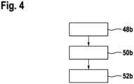
In einem ersten Verfahrensschritt 48b wird von einem Benutzer die Drehmomentstecknussvorrichtung 10b mit der als Handwerkzeugmaschine ausgebildeten externen Einheit 34b verbunden. Die externe Einheit 34b liest über die Kommunikations- und Auswertevorrichtung 44b die Identifikationseinheit 26b der Drehmomentstecknussvorrichtung 10b aus. Die Kommunikations- und Auswertevorrichtung 44b ermittelt aus dem von der Identifikationseinheit 26b bereitgestellten digitalen Signal die Drehmomentstecknussvorrichtungsparameter der Drehmomentstecknussvorrichtung 10b. Vorzugsweise erfasst die Kommunikations- und Auswertevorrichtung 44b als Drehmomentstecknussvorrichtungsparameter das Grenzdrehmoment, eine Toleranz, einen Durchmesser der Werkzeugaufnahme 16b, einen Durchmesser der Befestigungselementaufnahme 12b und/oder den Verschleißparameter.In a
In einem weiteren Verfahrensschritt 50b berechnet die Kommunikations- und Auswertevorrichtung 44b anhand der ermittelten Drehmomentstecknussvorrichtungsparameter eine vorteilhafte Einstellung der als Handwerkzeugmaschine ausgebildeten externen Einheit 34b. Vorzugsweise kann ein für die entsprechende Schraubung vorteilhaftes Drehmoment und Drehzahl der als Handwerkzeugmaschine ausgebildeten externen Einheit 34b eingestellt werden.In a
In einem weiteren Verfahrensschritt 52b wird die Schraubung durchgeführt. Die dabei zuvor ermittelten Drehmomentstecknussvorrichtungsparameter werden zusammen mit weiteren Prozessdaten in einer entsprechenden Datenbank in der Kommunikations- und Auswertevorrichtung 44b der externen Einheit 34b gespeichert. Ferner werden in dem Verfahrensschritt 52b Werkzeugmaschinenparameter der als Handwerkzeugmaschine ausgebildeten externen Einheit zu den Daten der Schraubung gespeichert. Vorzugsweise werden in einem weiteren Verfahrensschritt die gespeicherten Daten für die Schraubung an eine weitere externe Speichereinheit übermittelt. Durch das Verfahren gemäß den oben gezeigten Verfahrensschritten 48b, 50b, 52b kann eine Schraubung besonders vorteilhaft und einfach gespeichert und so protokolliert werden.In a
In den
Die Drehmomentstecknussvorrichtung 10c weist eine Drehmomentkupplung 20c auf. Die Drehmomentkupplung 20c ist zwischen der Befestigungselementaufnahme 12c und der Werkzeugaufnahme 16c angeordnet. Die Drehmomentkupplung 20c ist dazu vorgesehen, bei Erreichen eines Grenzdrehmoments die Befestigungselementaufnahme 12c und die Werkzeugaufnahme 16c zumindest teilweise voneinander zu entkoppeln. Die Drehmomentkupplung 20c weist eine Eingangsseite 22c auf, die dem axial hinteren Ende der Drehmomentstecknussvorrichtung 10c zugewandt ist. Die Drehmomentkupplung 20c weist eine Ausgangsseite 24c auf, die dem axial vorderen Ende Drehmomentstecknussvorrichtung 10c zugewandt ist. Die Drehmomentkupplung 20c weist einen nicht näher dargestellten Kupplungsmechanismus auf, über den die Eingangsseite 22c und die Ausgangsseite 24c miteinander verbunden sind.The
Die Drehmomentstecknussvorrichtung 10c weist eine Identifikationseinheit 26c auf. Die Identifikationseinheit 26c ist zu einer digitalen Kommunikation von zumindest einem Drehmomentstecknussvorrichtungsparameter vorgesehen. Ein Drehmomentstecknussvorrichtungsparameter, der von der Identifikationseinheit 26c zu einer digitalen Kommunikation vorgesehen ist, ist als das Grenzdrehmoment der Drehmomentkupplung 20c ausgebildet. Die Identifikationseinheit 26c weist ein optisches Identifikationselement 28c auf. Das optische Identifikationselement 28c ist als ein QR Code ausgebildet. In dem optischen Identifikationselement 28c sind die Drehmomentstecknussvorrichtungsparameter hinterlegt. Die Drehmomentstecknussvorrichtungsparameter sind mit einem entsprechenden Auslesegerät aus dem optischen Identifikationselement auslesbar. Grundsätzlich wäre es auch denkbar, dass die Identifikationseinheit 26c zusätzlich und äquivalent zum zweiten Ausführungsbeispiel ein Kommunikationsmodul zur elektronischen digitalen Übertragung aufweist.The
Das System umfasst zusätzlich eine Handwerkzeugmaschine 54c. Die Handwerkzeugmaschine 54c ist beispielhaft als ein Akkuschrauber ausgebildet. Grundsätzlich sind auch andere Handwerkzeugmaschinen denkbar. Mittels der Handwerkzeugmaschine 54c kann die Drehmomentstecknussvorrichtung 10c zum Durchführen von Schraubungen und zum entsprechenden Anziehen von Befestigungsmitteln mit einem definierten Drehmoment verwendet werden.The system also includes a
Die externe Einheit 34c des Systems ist als ein Zusatzhandgriff ausgebildet. Die als Zusatzhandgriff ausgebildet externe Einheit 34c ist dazu vorgesehen, mit der Handwerkzeugmaschine 54c verbunden zu werden. Die externe Einheit 34c ist als ein smarter Zusatzhandgriff ausgebildet. Die als Zusatzhandgriff ausgebildete externe Einheit 34c weist eine Kameraeinheit 56c auf, die dazu vorgesehen ist, einen von der Identifikationseinheit 26c optisch auslesbaren Drehmomentstecknussvorrichtungsparameter zu erfassen. Die Kameraeinheit 56c ist auf einer Vorderseite der externen Einheit 34c angeordnet und in einem an der Handwerkzeugmaschine 54c befestigten Zustand auf einen Arbeitsbereich, in dem die Drehmomentstecknussvorrichtung 10c angeordnet ist, ausgerichtet. Die externe Einheit 34c weist eine Kommunikations- und Auswertevorrichtung 44c auf. Die Kommunikations- und Auswertevorrichtung 44c ist dazu vorgesehen, den von der Identifikationseinheit 26c der Drehmomentstecknussvorrichtung 10c bereitgestellten Drehmomentstecknussvorrichtungsparameter zu empfangen, auszuwerten und/oder abzuspeichern. Die Kommunikations- und Auswertevorrichtung 44c ist dazu vorgesehen, ein von der Kameraeinheit 56c bereitgestelltes Bildmaterial auszuwerten und die in dem erfassten optischen Identifikationselement 28c hinterlegten Drehmomentstecknussvorrichtungsparameter zu ermitteln. Weist die Drehmomentstecknussvorrichtung 10c auch eine Verschleißindikatoreinheit auf, so ist es denkbar, dass auch diese von der Kameraeinheit 56c erfasst und von der Kommunikations- und Auswertevorrichtung 44c ausgewertet wird. Die als Zusatzhandgriff ausgebildete externe Einheit 34c weist vorzugsweise weitere Sensoren auf, wie einen Beschleunigungssensor, einen Neigungssensor und/oder weitere optische Sensoren, die jeweils ein Sensorsignal an die Kommunikations- und Auswertevorrichtung 44c ausgeben. Die Kommunikations- und Auswertevorrichtung 44c ist dazu vorgesehen, die von den Sensoren ausgegebenen Sensorsignale zu verarbeiten.The
Im Folgenden soll beispielhaft ein erfindungsgemäßes Verfahren mit einer erfindungsgemäßen Drehmomentstecknussvorrichtung 10c, der Handwerkzeugmaschine 54c und der als Zusatzhandgriff ausgebildeten externen Einheit 34c beschrieben werden. Insbesondere soll ein Verfahren einer Schraubung, also einer Drehmomentschraubung mittels der Drehmomentstecknussvorrichtung 10c beschrieben werden, bei der ein Verbindungsmittel, wie beispielsweise eine Schraube mit einem definierten Drehmoment angezogen wird.A method according to the invention with a
In einem ersten Verfahrensschritt 48c wird von einem Benutzer die Drehmomentstecknussvorrichtung 10c mit der Handwerkzeugmaschine 54c verbunden. Die als Zusatzhandgriff ausgebildete externe Einheit 34c liest über eine Kameraeinheit 56c und die Kommunikations- und Auswertevorrichtung 44c die Identifikationseinheit 26c, insbesondere das optische Identifikationselement 28c, der Drehmomentstecknussvorrichtung 10c aus. Die ausgelesenen Drehmomentstecknussvorrichtungsparameter werden in der Kommunikations- und Auswertevorrichtung 44c zwischengespeichert.In a
In einem weiteren Verfahrensschritt 50c erfasst und verarbeitet die Kommunikations- und Auswertevorrichtung 44c der als Zusatzhandgriff ausgebildeten externen Einheit Parameter der Handwerkzeugmaschine 54c aus. Anhand der ermittelten Drehmomentstecknussvorrichtungsparameter der Drehmomentstecknussvorrichtung 10c und der Parameter der Handwerkzeugmaschine 54c, ermittelt die Kommunikations- und Auswertevorrichtung 44c vorteilhafte Einstellungen für die Handwerkzeugmaschine 54c zur Durchführung der Schraubung, und kann diese an die Handwerkzeugmaschine 54c übermitteln.In a
In einem weiteren Verfahrensschritt 52c wird die Schraubung durchgeführt. Die dabei zuvor ermittelten Drehmomentstecknussvorrichtungsparameter werden zusammen mit weiteren Prozessdaten in einer entsprechenden Datenbank in der Kommunikations- und Auswertevorrichtung 44c der als Zusatzhandgriff ausgebildeten externen Einheit 34c gespeichert. Ferner werden die Sensorsignale der weiteren Sensoren der externen Einheit 34c während der Schraubung ebenfalls ausgewertet und gespeichert. Zudem erfasst die Kommunikations- und Auswertevorrichtung 44c während der Schraubung ebenfalls Werkzeugmaschinenparameter der Handwerkzeugmaschine 54c. Vorzugsweise überwacht die Kommunikations- und Auswertevorrichtung 44c anhand der erfassten Parameter die Schraubung und gibt der Handwerkzeugmaschine 54c ein Signal aus, wenn ein Zielwert der Schraubung, beispielsweise das korrekte Drehmoment, oder eine Einschraubtiefe erreicht ist. Die erfassten Parameter werden für die entsprechende Schraubung in einer Datenbank gespeichert. Vorzugsweise werden in einem weiteren Verfahrensschritt die gespeicherten Daten für die Schraubung an eine weitere externe Speichereinheit übermittelt.In a
Claims (10)
Translated fromGermanPriority Applications (2)
| Application Number | Priority Date | Filing Date | Title |
|---|---|---|---|
| DE102021214594.9ADE102021214594A1 (en) | 2021-12-17 | 2021-12-17 | Hand-held power tool assembly with torque socket assembly and method |
| EP22212093.3AEP4197695A1 (en) | 2021-12-17 | 2022-12-08 | Hand-held power tool device with torque nut device and method |
Applications Claiming Priority (1)
| Application Number | Priority Date | Filing Date | Title |
|---|---|---|---|
| DE102021214594.9ADE102021214594A1 (en) | 2021-12-17 | 2021-12-17 | Hand-held power tool assembly with torque socket assembly and method |
Publications (1)
| Publication Number | Publication Date |
|---|---|
| DE102021214594A1true DE102021214594A1 (en) | 2023-06-22 |
Family
ID=84462744
Family Applications (1)
| Application Number | Title | Priority Date | Filing Date |
|---|---|---|---|
| DE102021214594.9APendingDE102021214594A1 (en) | 2021-12-17 | 2021-12-17 | Hand-held power tool assembly with torque socket assembly and method |
Country Status (2)
| Country | Link |
|---|---|
| EP (1) | EP4197695A1 (en) |
| DE (1) | DE102021214594A1 (en) |
Citations (5)
| Publication number | Priority date | Publication date | Assignee | Title |
|---|---|---|---|---|
| DE4017984A1 (en) | 1990-06-05 | 1991-12-12 | Mohilo Oskar | Adaptor for bolt spanner for controlled tightening - has torque digital indicator and simple programming using rotatable control ring |
| DE202010014534U1 (en) | 2010-10-20 | 2011-03-17 | Legend Lifestyle Products Corp., Neihu | Multifunctional torque tool detection device |
| DE102015115894A1 (en) | 2014-11-03 | 2016-05-04 | The Boeing Company | Certifiable fasteners and related systems and methods |
| DE202017005554U1 (en) | 2017-10-26 | 2017-12-01 | Christoph Görner | Socket wrench for screwing in threaded elements |
| DE102019116709A1 (en) | 2019-01-10 | 2020-07-16 | China Pneumatic Corporation | Torque detection and transmission device |
Family Cites Families (6)
| Publication number | Priority date | Publication date | Assignee | Title |
|---|---|---|---|---|
| SE8802566L (en)* | 1988-07-08 | 1990-01-09 | Atlas Copco Tools Ab | THE ENGINE OPERATED TOOL AND DRIVE SYSTEM DOES THIS |
| USH1821H (en)* | 1997-07-02 | 1999-12-07 | Caterpillar, Incorporated | Method and apparatus for operating a driver and an associated number of work tools |
| GB0222296D0 (en)* | 2002-09-25 | 2002-10-30 | Fast Technology Ag | Torque signal transmission |
| EP1439035A1 (en)* | 2002-12-16 | 2004-07-21 | Fast Technology AG | Signal processing and control device for a power torque tool |
| TWI680839B (en)* | 2019-03-20 | 2020-01-01 | 黃鴻文 | Torque sleeve |
| TWI711510B (en)* | 2019-12-24 | 2020-12-01 | 黃鴻文 | Torque sleeve |
- 2021
- 2021-12-17DEDE102021214594.9Apatent/DE102021214594A1/enactivePending
- 2022
- 2022-12-08EPEP22212093.3Apatent/EP4197695A1/ennot_activeWithdrawn
Patent Citations (5)
| Publication number | Priority date | Publication date | Assignee | Title |
|---|---|---|---|---|
| DE4017984A1 (en) | 1990-06-05 | 1991-12-12 | Mohilo Oskar | Adaptor for bolt spanner for controlled tightening - has torque digital indicator and simple programming using rotatable control ring |
| DE202010014534U1 (en) | 2010-10-20 | 2011-03-17 | Legend Lifestyle Products Corp., Neihu | Multifunctional torque tool detection device |
| DE102015115894A1 (en) | 2014-11-03 | 2016-05-04 | The Boeing Company | Certifiable fasteners and related systems and methods |
| DE202017005554U1 (en) | 2017-10-26 | 2017-12-01 | Christoph Görner | Socket wrench for screwing in threaded elements |
| DE102019116709A1 (en) | 2019-01-10 | 2020-07-16 | China Pneumatic Corporation | Torque detection and transmission device |
Also Published As
| Publication number | Publication date |
|---|---|
| EP4197695A1 (en) | 2023-06-21 |
Similar Documents
| Publication | Publication Date | Title |
|---|---|---|
| DE60032194T2 (en) | Dressing tool with exchangeable insert | |
| EP1125174B1 (en) | Processing tool and processing device for processing a workpiece | |
| DE102011104901B4 (en) | Powered hand tool machine | |
| DE102013200602B4 (en) | Power tool with improved usability | |
| EP3946818B1 (en) | Method for detecting a first operating state of a handheld power tool | |
| EP3349943B1 (en) | Tool system with power wrench and external operating part | |
| DE102017104224A1 (en) | Monitoring system and screw connection monitoring method | |
| EP4221940B1 (en) | Electric handheld machine tool | |
| DE112010005996T5 (en) | Drive unit for a power tool | |
| DE102019211303A1 (en) | Method for recognizing the work progress of a hand machine tool | |
| DE102006007990A1 (en) | Hand-operated machine tool e.g. battery-operated drilling machine, for machining work piece, has measuring unit for transmitting measuring signal, where work progress parameter is implemented as geometrical parameter of measuring signal | |
| DE102019211305A1 (en) | Method for operating a hand machine tool | |
| EP3375571A2 (en) | Sensor system for an electric screwdriver for classifying screw processes by means of a magnetic field sensor | |
| EP1748869A1 (en) | Method and device for producing screw connections | |
| DE102017203149A1 (en) | Electric hand tool with a sensor device and method for operating an electric hand tool | |
| DE4243069C2 (en) | Pulse tool, especially pulse screwdriver | |
| DE102021214594A1 (en) | Hand-held power tool assembly with torque socket assembly and method | |
| EP3833510B1 (en) | Hand-held machine tool and method for operating a hand-held machine tool | |
| DE102017206064A1 (en) | Hand tool | |
| DE102019200323A1 (en) | Machine tool | |
| EP4086044A1 (en) | Hand-held device with detection and control units | |
| DE102018208636A1 (en) | Method for the electronic detection of a locked state of a coupling unit | |
| DE102018107726B4 (en) | Tool for machining a workpiece and recording machining points | |
| DE102008043791A1 (en) | Hand machine tool device | |
| DE102016218775A1 (en) | Hand tool system |
Legal Events
| Date | Code | Title | Description |
|---|---|---|---|
| R163 | Identified publications notified |