DE102021207032A1 - SA automotive radar sensor - Google Patents
SA automotive radar sensorDownload PDFInfo
- Publication number
- DE102021207032A1 DE102021207032A1DE102021207032.9ADE102021207032ADE102021207032A1DE 102021207032 A1DE102021207032 A1DE 102021207032A1DE 102021207032 ADE102021207032 ADE 102021207032ADE 102021207032 A1DE102021207032 A1DE 102021207032A1
- Authority
- DE
- Germany
- Prior art keywords
- module
- coefficients
- radar
- fft
- recursion
- Prior art date
- Legal status (The legal status is an assumption and is not a legal conclusion. Google has not performed a legal analysis and makes no representation as to the accuracy of the status listed.)
- Pending
Links
- 230000009466transformationEffects0.000claimsabstractdescription40
- 230000006870functionEffects0.000claimsabstractdescription27
- 238000004364calculation methodMethods0.000claimsabstractdescription14
- 238000011156evaluationMethods0.000claimsabstractdescription13
- 238000005070samplingMethods0.000claimsabstractdescription10
- 230000008859changeEffects0.000claimsabstractdescription9
- 238000013508migrationMethods0.000claimsabstractdescription8
- 230000005012migrationEffects0.000claimsabstractdescription8
- 230000000694effectsEffects0.000claimsabstractdescription7
- 238000002592echocardiographyMethods0.000claimsabstractdescription6
- 238000000844transformationMethods0.000claimsdescription3
- 230000036962time dependentEffects0.000claims1
- 238000005259measurementMethods0.000description16
- 230000008901benefitEffects0.000description5
- 238000009825accumulationMethods0.000description4
- 238000010586diagramMethods0.000description4
- 238000000034methodMethods0.000description4
- 239000013598vectorSubstances0.000description4
- 230000035559beat frequencyEffects0.000description3
- 238000013459approachMethods0.000description2
- 238000011157data evaluationMethods0.000description2
- 230000001419dependent effectEffects0.000description2
- 230000010354integrationEffects0.000description2
- 238000001208nuclear magnetic resonance pulse sequenceMethods0.000description2
- 238000012545processingMethods0.000description2
- 230000005540biological transmissionEffects0.000description1
- 238000011161developmentMethods0.000description1
- 230000018109developmental processEffects0.000description1
- 230000002349favourable effectEffects0.000description1
- 238000011835investigationMethods0.000description1
- 239000011159matrix materialSubstances0.000description1
- 230000008569processEffects0.000description1
- 230000009467reductionEffects0.000description1
- 238000004904shorteningMethods0.000description1
- 238000001228spectrumMethods0.000description1
Images


Classifications
- G—PHYSICS
- G01—MEASURING; TESTING
- G01S—RADIO DIRECTION-FINDING; RADIO NAVIGATION; DETERMINING DISTANCE OR VELOCITY BY USE OF RADIO WAVES; LOCATING OR PRESENCE-DETECTING BY USE OF THE REFLECTION OR RERADIATION OF RADIO WAVES; ANALOGOUS ARRANGEMENTS USING OTHER WAVES
- G01S13/00—Systems using the reflection or reradiation of radio waves, e.g. radar systems; Analogous systems using reflection or reradiation of waves whose nature or wavelength is irrelevant or unspecified
- G01S13/02—Systems using reflection of radio waves, e.g. primary radar systems; Analogous systems
- G01S13/06—Systems determining position data of a target
- G01S13/08—Systems for measuring distance only
- G01S13/32—Systems for measuring distance only using transmission of continuous waves, whether amplitude-, frequency-, or phase-modulated, or unmodulated
- G—PHYSICS
- G01—MEASURING; TESTING
- G01S—RADIO DIRECTION-FINDING; RADIO NAVIGATION; DETERMINING DISTANCE OR VELOCITY BY USE OF RADIO WAVES; LOCATING OR PRESENCE-DETECTING BY USE OF THE REFLECTION OR RERADIATION OF RADIO WAVES; ANALOGOUS ARRANGEMENTS USING OTHER WAVES
- G01S13/00—Systems using the reflection or reradiation of radio waves, e.g. radar systems; Analogous systems using reflection or reradiation of waves whose nature or wavelength is irrelevant or unspecified
- G01S13/88—Radar or analogous systems specially adapted for specific applications
- G01S13/89—Radar or analogous systems specially adapted for specific applications for mapping or imaging
- G01S13/90—Radar or analogous systems specially adapted for specific applications for mapping or imaging using synthetic aperture techniques, e.g. synthetic aperture radar [SAR] techniques
- G01S13/9021—SAR image post-processing techniques
- G—PHYSICS
- G01—MEASURING; TESTING
- G01S—RADIO DIRECTION-FINDING; RADIO NAVIGATION; DETERMINING DISTANCE OR VELOCITY BY USE OF RADIO WAVES; LOCATING OR PRESENCE-DETECTING BY USE OF THE REFLECTION OR RERADIATION OF RADIO WAVES; ANALOGOUS ARRANGEMENTS USING OTHER WAVES
- G01S13/00—Systems using the reflection or reradiation of radio waves, e.g. radar systems; Analogous systems using reflection or reradiation of waves whose nature or wavelength is irrelevant or unspecified
- G01S13/02—Systems using reflection of radio waves, e.g. primary radar systems; Analogous systems
- G01S13/06—Systems determining position data of a target
- G01S13/08—Systems for measuring distance only
- G01S13/32—Systems for measuring distance only using transmission of continuous waves, whether amplitude-, frequency-, or phase-modulated, or unmodulated
- G01S13/34—Systems for measuring distance only using transmission of continuous waves, whether amplitude-, frequency-, or phase-modulated, or unmodulated using transmission of continuous, frequency-modulated waves while heterodyning the received signal, or a signal derived therefrom, with a locally-generated signal related to the contemporaneously transmitted signal
- G01S13/343—Systems for measuring distance only using transmission of continuous waves, whether amplitude-, frequency-, or phase-modulated, or unmodulated using transmission of continuous, frequency-modulated waves while heterodyning the received signal, or a signal derived therefrom, with a locally-generated signal related to the contemporaneously transmitted signal using sawtooth modulation
- G—PHYSICS
- G01—MEASURING; TESTING
- G01S—RADIO DIRECTION-FINDING; RADIO NAVIGATION; DETERMINING DISTANCE OR VELOCITY BY USE OF RADIO WAVES; LOCATING OR PRESENCE-DETECTING BY USE OF THE REFLECTION OR RERADIATION OF RADIO WAVES; ANALOGOUS ARRANGEMENTS USING OTHER WAVES
- G01S13/00—Systems using the reflection or reradiation of radio waves, e.g. radar systems; Analogous systems using reflection or reradiation of waves whose nature or wavelength is irrelevant or unspecified
- G01S13/88—Radar or analogous systems specially adapted for specific applications
- G01S13/89—Radar or analogous systems specially adapted for specific applications for mapping or imaging
- G01S13/90—Radar or analogous systems specially adapted for specific applications for mapping or imaging using synthetic aperture techniques, e.g. synthetic aperture radar [SAR] techniques
- G01S13/9004—SAR image acquisition techniques
- G—PHYSICS
- G01—MEASURING; TESTING
- G01S—RADIO DIRECTION-FINDING; RADIO NAVIGATION; DETERMINING DISTANCE OR VELOCITY BY USE OF RADIO WAVES; LOCATING OR PRESENCE-DETECTING BY USE OF THE REFLECTION OR RERADIATION OF RADIO WAVES; ANALOGOUS ARRANGEMENTS USING OTHER WAVES
- G01S13/00—Systems using the reflection or reradiation of radio waves, e.g. radar systems; Analogous systems using reflection or reradiation of waves whose nature or wavelength is irrelevant or unspecified
- G01S13/88—Radar or analogous systems specially adapted for specific applications
- G01S13/93—Radar or analogous systems specially adapted for specific applications for anti-collision purposes
- G01S13/931—Radar or analogous systems specially adapted for specific applications for anti-collision purposes of land vehicles
- G—PHYSICS
- G01—MEASURING; TESTING
- G01S—RADIO DIRECTION-FINDING; RADIO NAVIGATION; DETERMINING DISTANCE OR VELOCITY BY USE OF RADIO WAVES; LOCATING OR PRESENCE-DETECTING BY USE OF THE REFLECTION OR RERADIATION OF RADIO WAVES; ANALOGOUS ARRANGEMENTS USING OTHER WAVES
- G01S7/00—Details of systems according to groups G01S13/00, G01S15/00, G01S17/00
- G01S7/02—Details of systems according to groups G01S13/00, G01S15/00, G01S17/00 of systems according to group G01S13/00
- G01S7/28—Details of pulse systems
- G01S7/285—Receivers
- G01S7/288—Coherent receivers
- G01S7/2883—Coherent receivers using FFT processing
- G—PHYSICS
- G01—MEASURING; TESTING
- G01S—RADIO DIRECTION-FINDING; RADIO NAVIGATION; DETERMINING DISTANCE OR VELOCITY BY USE OF RADIO WAVES; LOCATING OR PRESENCE-DETECTING BY USE OF THE REFLECTION OR RERADIATION OF RADIO WAVES; ANALOGOUS ARRANGEMENTS USING OTHER WAVES
- G01S7/00—Details of systems according to groups G01S13/00, G01S15/00, G01S17/00
- G01S7/02—Details of systems according to groups G01S13/00, G01S15/00, G01S17/00 of systems according to group G01S13/00
- G01S7/35—Details of non-pulse systems
- G01S7/352—Receivers
- G01S7/356—Receivers involving particularities of FFT processing
- G—PHYSICS
- G01—MEASURING; TESTING
- G01S—RADIO DIRECTION-FINDING; RADIO NAVIGATION; DETERMINING DISTANCE OR VELOCITY BY USE OF RADIO WAVES; LOCATING OR PRESENCE-DETECTING BY USE OF THE REFLECTION OR RERADIATION OF RADIO WAVES; ANALOGOUS ARRANGEMENTS USING OTHER WAVES
- G01S7/00—Details of systems according to groups G01S13/00, G01S15/00, G01S17/00
- G01S7/02—Details of systems according to groups G01S13/00, G01S15/00, G01S17/00 of systems according to group G01S13/00
- G01S7/40—Means for monitoring or calibrating
Landscapes
- Engineering & Computer Science (AREA)
- Remote Sensing (AREA)
- Radar, Positioning & Navigation (AREA)
- Physics & Mathematics (AREA)
- Computer Networks & Wireless Communication (AREA)
- General Physics & Mathematics (AREA)
- Electromagnetism (AREA)
- Radar Systems Or Details Thereof (AREA)
Abstract
Translated fromGermanDescription
Translated fromGermanDie Erfindung betrifft einen Radarsensor für Kraftfahrzeuge, mit einem Hochfrequenzteil, der dazu konfiguriert ist, Folgen von modulierten Radarpulsen zu senden und die entsprechenden Radarechos zu empfangen, und einem elektronischen Auswerteteil, der dazu konfiguriert ist, Abstands- und Winkelmessungen nach dem Prinzip der synthetischen Apertur (SA) vorzunehmen, und der aufweist:
- - ein Abtastmodul, das dazu konfiguriert ist, die Amplituden der empfangenen Radarechos als Rohdaten in einem zweidimensionalen Datenraum abzutasten, in dem eine Dimension die zeitliche Veränderung der Amplituden innerhalb eines Radarpulses repräsentiert und die andere Dimension die Änderung der Amplituden von Puls zu Puls repräsentiert,
- - ein FFT-Modul mit spezialisierter Hardware für die Ausführung von schnellen Fourier-Transformationen (FFT) zur Berechnung eines zweidimensionalen Abstands-Geschwindigkeits-Radarbildes,
- - ein Transformationsmodul, das dazu konfiguriert ist, die Rohdaten bei gleichzeitiger Korrektur von Migrationseffekten in ein von dem FFT-Modul verarbeitbares Format zu transformieren, durch Anwendung einer Transformationsfunktion, die durch eine Anzahl N von Koeffizienten definiert ist, und
- - ein Koeffizientenmodul zur Bereitstellung der Koeffizienten für das Transformationsmodul.
- - a sampling module configured to sample the amplitudes of the received radar echoes as raw data in a two-dimensional data space, in which one dimension represents the change in the amplitudes over time within a radar pulse and the other dimension represents the change in the amplitudes from pulse to pulse,
- - an FFT module with specialized hardware for performing Fast Fourier Transforms (FFT) to calculate a two-dimensional range-velocity radar image,
- - a transformation module configured to transform the raw data into a format processable by the FFT module, while correcting for migration effects, by applying a transformation function defined by a number N of coefficients, and
- - a coefficient module for providing the coefficients for the transformation module.
Stand der TechnikState of the art
Radarsysteme zur Messung von Abständen, Relativgeschwindigkeiten und Winkeln von Objekten (wie z. B. von Fahrzeugen und Hindernissen) werden zunehmend in KFZ für Sicherheits- und Komfortfunktionen eingesetzt. Seit einigen Jahren wird die Verwendung von Radarsensoren mit synthetischer Apertur (SA) im Automobilbereich untersucht. Das Prinzip der synthetischen Apertur erlaubt bei Eigenbewegung des Radarsensors besonders genaue Winkelmessungen, indem die Messungen an unterschiedlichen örtlichen Positionen als eine synthetische Antennenapertur (Antennenfläche) interpretiert und entsprechend verarbeitet werden. Die synthetische Apertur kommt dadurch zustande, dass sich die Sende- und Empfangsantennen zum Zeitpunkt jeder einzelnen Messung wegen der Eigenbewegung des Radars an unterschiedlichen örtlichen Positionen befinden und somit rechnerisch so behandelt werden können, als sei entlang der Fahrttrajektorie eine große Antennenapertur vorhanden. Damit sind mit einzelnen Sende- und Empfangsantennen Auflösungen in der Winkelmessung möglich, die mit der vorhandenen realen Antennenapertur unerreichbar wären.Radar systems for measuring distances, relative speeds and angles of objects (such as vehicles and obstacles) are increasingly being used in motor vehicles for safety and comfort functions. The use of synthetic aperture (SA) radar sensors in automotive applications has been under investigation for several years. The principle of the synthetic aperture allows particularly precise angle measurements when the radar sensor is moving itself, in that the measurements at different local positions are interpreted as a synthetic antenna aperture (antenna surface) and processed accordingly. The synthetic aperture is due to the fact that the transmitting and receiving antennas are in different local positions at the time of each individual measurement due to the radar's own movement and can therefore be treated mathematically as if there were a large antenna aperture along the travel trajectory. This means that resolutions in the angle measurement are possible with individual transmitting and receiving antennas that would be unattainable with the existing real antenna aperture.
Heutige Kfz-Radarsysteme setzen in der Regel eine FMCW-Modulation mit schnellen Rampen (Fast-Chirp-Modulation) ein, bei der nacheinander mehrere lineare Frequenzrampen (frequenzmodulierte Pulse) mit derselben Steigung gesendet werden. Die Mischung des momentanen Sendesignals mit dem Empfangssignal ergibt ein niederfrequentes Signal (Beatfrequenz genannt), dessen Frequenz zum Abstand proportional ist. Das System wird in der Regel so ausgelegt, dass der durch die Dopplerverschiebung bei radialer Relativbewegung des Objekts versursachte Anteil an der Beatfrequenz vernachlässigbar ist. Die gewonnene Abstandsinformation ist dann weitgehend eindeutig. Die Dopplerverschiebung - und damit die Radialgeschwindigkeit - kann anschließend durch Beobachtung der zeitlichen Entwicklung der Phase des komplexen Abstandssignals über die Rampen hinweg bestimmt werden. Abstands- und Geschwindigkeitsbestimmung finden unabhängig voneinander statt, in der Regel mittels zweidimensionaler schneller Fourier-Transformation (engl. fast Fourier transform, FFT).Today's automotive radar systems generally use FMCW modulation with fast ramps (fast chirp modulation), in which several linear frequency ramps (frequency-modulated pulses) with the same gradient are sent one after the other. Mixing the instantaneous transmitted signal with the received signal results in a low-frequency signal (called the beat frequency) whose frequency is proportional to the distance. The system is usually designed in such a way that the proportion of the beat frequency caused by the Doppler shift during radial relative movement of the object is negligible. The distance information obtained is then largely unambiguous. The Doppler shift - and thus the radial velocity - can then be determined by observing the time evolution of the phase of the complex distance signal across the ramps. Distance and speed determination take place independently of each other, usually by means of a two-dimensional fast Fourier transform (FFT).
Auch bei einem SA-Radar kann das Messprinzip der Fast-Chirp-Modulation verwendet werden. Die Abstandsauswertung bleibt weitgehend unverändert. Die Dopplerauswertung über die Rampen hinweg wird nun durch eine SA-Auswertung ersetzt. Diese liefert im Endergebnis nicht eine Dopplermessung, sondern unter der Annahme von stationären Zielen und mit Kenntnis der Eigenbewegung des Fahrzeugs eine Winkelmessung. Hierzu wird die sich aus der Dopplermessung ergebende Relativgeschwindigkeit des Objekts ausgewertet, die eine Projektion der Eigengeschwindigkeit auf die Sichtachse zum Objekt ist.The measurement principle of fast chirp modulation can also be used with an SA radar. The distance evaluation remains largely unchanged. The Doppler evaluation across the ramps is now replaced by an SA evaluation. The end result is not a Doppler measurement, but rather an angle measurement, assuming stationary targets and with knowledge of the vehicle's own movement. For this purpose, the relative speed of the object resulting from the Doppler measurement is evaluated, which is a projection of the own speed onto the line of sight to the object.
Für die Datenauswertung nach dem Prinzip der synthetischen Apertur ist zwar eine Eigenbewegung des Fahrzeugs erforderlich, damit überhaupt eine synthetische Apertur entsteht, jedoch wird die Berechnung des Abstands-Geschwindigkeits-Radarbildes dadurch erschwert, dass aufgrund der Eigenbewegung des Fahrzeugs die stationären Objekte, deren Winkel gemessen werden sollen, während der Dauer des Messzyklus eine scheinbare Ortsveränderung (Migration) erfahren, die zu Verzerrungen des Radarbildes führt.Although the vehicle's own movement is necessary for the data evaluation according to the principle of the synthetic aperture so that a synthetic aperture is created at all, the calculation of the distance-velocity radar image is made more difficult by the fact that the stationary objects and their angles are measured due to the vehicle's own movement are to experience an apparent change in location (migration) during the measurement cycle, which leads to distortions in the radar image.
In der Literatur ist eine Anzahl von Algorithmen bekannt, mit denen solche Migrationseffekte korrigiert werden. Konzeptuell kann man dabei zwischen zwei Klassen von Algorithmen unterscheiden: (a) Algorithmen, die auf Kosten größeren Rechenaufwands in der Lage sind, eine beliebige synthetische Apertur zu verarbeiten (z.B. back projection), und (b) andere, die sich auf einen gewissen Aperturtyp einschränken (z.B. linear), dafür aber recheneffizienter sind (z.B. der Keystone-Algorithmus). Dabei ist in der Automotive Anwendung die effiziente Berechnung des Abstands-Geschwindigkeits-Radarbildes und es sich daraus ergebenden Abstands-Winkel-Radarbildes von großer Bedeutung, da eine Echtzeitverarbeitung erforderlich ist.A number of algorithms are known in the literature for correcting such migration effects. Conceptually, one can distinguish between two classes of algorithms: (a) algorithms that are able to process any synthetic aperture (e.g. back projection) at the expense of greater computational effort, and (b) others that focus on a certain aperture type (e.g. linear), but are more computationally efficient (e.g. the Keystone algorithm). The efficient calculation of the distance-speed radar image and the resulting distance-angle radar image is of great importance in the automotive application, since real-time processing is required.
Um eine hohe Recheneffizienz und damit Echtzeitverarbeitung zu erreichen, werden in konventionellen KFZ-Radarsensoren Beschleuniger für die FFT-Operationen eingesetzt. Z.B. ist der Kern des Keystone-Algorithmus eine sogenannte Chirp-Z-Transformation, die als Faltung zweier Funktionen betrachtet werden kann, zu deren Berechnung ebenfalls FFT-Beschleuniger eingesetzt werden können. Dazu müssen die Koeffizienten der Chirp-Z-Transformation, die in die schnelle Faltung eingehen, entweder vorab berechnet und in einen Speicher geschrieben werden oder aber sie müssen online berechnet werden. Der erstere Ansatz benötigt zusätzlichen Speicher, während der letztere Ansatz komplexe Exponenten-Berechnungen in Echtzeit erfordert.In order to achieve high computing efficiency and thus real-time processing, accelerators are used for the FFT operations in conventional vehicle radar sensors. For example, the core of the Keystone algorithm is a so-called Chirp-Z-Transform, which can be viewed as a convolution of two functions that can also be calculated using FFT accelerators. To do this, the chirp Z-transform coefficients that go into the fast convolution must either be precomputed and written to memory, or they must be computed online. The former approach requires additional memory, while the latter approach requires complex real-time exponent calculations.
Offenbarung der ErfindungDisclosure of Invention
Aufgabe der Erfindung ist es, einen Radarsensor zu schaffen, der nur wenig Speicherplatz für die Speicherung der Koeffizienten der Transformationsfunktion benötigt, mit dem es aber dennoch möglich ist, die für die Echtzeit-Berechnung des Radarbildes benötigten Koeffizienten schnell genug bereitzustellen.The object of the invention is to create a radar sensor that requires only little storage space for storing the coefficients of the transformation function, but with which it is nevertheless possible to provide the coefficients required for real-time calculation of the radar image quickly enough.
Diese Aufgabe wird erfindungsgemäß dadurch gelöst, dass das Koeffizientenmodul aufweist:
- - einen Speicher, in dem ein Anfangssatz von Koeffizienten gespeichert ist, der weniger als N Koeffizienten umfasst, und
- - ein Rekursionsmodul zur rekursiven Berechnung der übrigen Koeffizienten.
- - a memory in which is stored an initial set of coefficients comprising fewer than N coefficients, and
- - a recursion module for the recursive calculation of the remaining coefficients.
Die Erfindung nutzt den Umstand aus, dass die benötigten Koeffizienten der Transformationsfunktion rekursiv berechnet werden können. Da die Rohdaten, auf welche die Transformation angewandt wird, in einem zweidimensionalen Datenraum definiert sind, ist auch die Transformationsfunktion auf einem zweidimensionalen Raum definiert, und ihre Koeffizienten c(n, k) sind folglich Funktionen zweier Indizes n und k. So kann man als Anfangssatz beispielsweise die Koeffizienten c(0, k) speichern und die übrigen Koeffizienten c(n, k) mit n > 0 anhand einer Rekursionsformel c(n, k) = f(c(n-1, k)) berechnen. Es zeigt sich, dass sich die Koeffizienten auf diese Weise deutlich schneller berechnen lassen als bei einem herkömmlichen Algorithmus, bei dem die Koeffizienten für die Indexpaare (n, k) einzeln und unabhängig voneinander berechnet werden. Auf diese Weise gelingt es, die Koeffizienten so schnell bereitzustellen, wie sie für die Ausführung der Transformation in Echtzeit benötigt werden. Wenn die Anzahl der Koeffizienten n, also die Größe des Datenraumes in der ersten Dimension, mit Nfast bezeichnet wird und die Anzahl der Koeffizienten k in der zweiten Dimension Nslow, so ist der Speicherplatzbedarf für die Koeffizienten bei dem erfindungsgemäßen Verfahren nicht proportional zu Nfast × Nslow, sondern nur proportional zu entweder Nfast oder Nslow. Da die Anzahlen Nfast und Nslow relativ groß sein müssen, beispielweise 256 bzw. 512, damit die SA-Auswertung mit hinreichender Genauigkeit ausgeführt werden kann, und da es sich bei den Koeffizienten außerdem um komplexe Zahlen handelt, kann durch die rekursive Berechnung der Koeffizienten beträchtlicher Speicherplatz eingespart werden.The invention makes use of the fact that the required coefficients of the transformation function can be calculated recursively. Since the raw data on which the transformation is applied is defined in a two-dimensional data space, the transformation function is also defined in a two-dimensional space and its coefficients c(n,k) are consequently functions of two indices n and k. For example, one can store the coefficients c(0, k) as the initial set and the remaining coefficients c(n, k) with n > 0 using a recursion formula c(n, k) = f(c(n-1, k)) to calculate. It turns out that the coefficients can be calculated much faster in this way than with a conventional algorithm in which the coefficients for the index pairs (n, k) are calculated individually and independently of one another. In this way, it is possible to provide the coefficients as quickly as they are needed to execute the transformation in real time. If the number of coefficients n, i.e. the size of the data space in the first dimension, is denoted by Nfast and the number of coefficients k in the second dimension by Nslow , the memory space required for the coefficients in the method according to the invention is not proportional to Nfast × Nslow , but only proportional to either Nfast or Nslow . Since the numbers Nfast and Nslow must be relatively large, for example 256 and 512, respectively, so that the SA evaluation can be carried out with sufficient accuracy, and since the coefficients are also complex numbers, the recursive calculation of the Coefficients considerable storage space can be saved.
Die Erfindung ist nicht auf die Datenauswertung nach dem Keystone-Algorithmus beschränkt, sondern lässt sich generell bei allen Auswertungsalgorithmen anwenden, bei denen die Koeffizienten der Transformationsfunktion rekursiv berechnet werden können. Ebenso wenig ist die Erfindung auf ein Rapid Chirp FMCW-Radar beschränkt, sondern generell bei Radarsensoren anwendbar, bei denen das Sendesignal aus modulierten, beispielsweise phasenmodulierten, Pulsfolgen besteht.The invention is not limited to data evaluation using the Keystone algorithm, but can be used in general with all evaluation algorithms in which the coefficients of the transformation function can be calculated recursively. The invention is also not limited to a rapid chirp FMCW radar, but can generally be used with radar sensors in which the transmission signal consists of modulated, for example phase-modulated, pulse sequences.
Vorteilhafte Ausgestaltungen und Weiterbildungen der Erfindung sind in den Unteransprüchen angegeben.Advantageous refinements and developments of the invention are specified in the dependent claims.
Wenn es sich bei der Transformation der Rohdaten mathematisch um eine Faltung handelt, lässt sich die im Radarsensor vorhandene spezialisierte Hardware für schnelle Fourier-Transformationen auch zur Berechnung der durch die Koeffizienten definierten Transformation einsetzen, beispielsweise indem die Rohdaten und auch die Transformationsfunktion mittels FFT aus der Zeitdomäne in die Frequenzdomäne transformiert werden, die Funktionen dann in der Frequenzdomäne multipliziert und danach mittels inverser FFT wieder in die Zeitdomäne zurücktransformiert werden, bevor dann im FFT-Modul die zweidimensionale Fouriertransformation zur Berechnung des Abstands-Geschwindigkeits-Radarbildes ausgeführt wird.If the transformation of the raw data is mathematically a convolution, the specialized hardware available in the radar sensor for fast Fourier transformations can also be used to calculate the transformation defined by the coefficients, for example by using FFT to extract the raw data and the transformation function from the time domain are transformed into the frequency domain, the functions are then multiplied in the frequency domain and then transformed back into the time domain using inverse FFT before the two-dimensional Fourier transformation is then carried out in the FFT module to calculate the distance-velocity radar image.
Bei dem gespeicherten Anfangssatz der Koeffizienten muss es sich nicht um einen einzelnen Vektor (mit den Indizes n oder k als Komponenten) handeln, sondern es können beispielsweise zwei oder mehr solcher Vektoren gespeichert werden. Wenn Nfast oder Nslow sehr groß ist, hat das den Vorteil, dass die Akkumulation von Rundungsfehlern unterdrückt wird, weil die berechneten Koeffizienten dann mehrere kurze rekursive Folgen anstelle einer einzigen sehr langen Folge bilden.The initial set of coefficients stored need not be a single vector (having indices n or k as components), but two or more such vectors may be stored, for example. If Nfast or Nslow is very large, this has the advantage that the accumulation of rounding errors is suppressed because the calculated coefficients then form multiple short recursive sequences instead of a single very long sequence.
Wenn die Matrix der Koeffizienten n, k einen oder mehrere Blöcke bildet, kann es auch zweckmäßig sein, die Rekursion mit einem gespeicherten Anfangssatz von Koeffizienten für eine Spalte oder Zeile in der Mitte des jeweiligen Blockes zu beginnen und dann mit zwei separaten Rekursionsfolgen in entgegengesetzte Richtungen in dem Block fortzuschreiten. Dadurch wird nicht nur die Länge der Rekursionsfolgen halbiert und somit der Rundungsfehler verkleinert, sondern zugleich erreicht, dass größere Rundungsfehler allenfalls an den Rändern des Blockes auftreten, wo die Daten ohnehin durch eine Fensterfunktion herunterskaliert werden, so dass die Fehler sich weniger stark auswirken.If the matrix of coefficients n, k forms one or more blocks, it may also be convenient to start the recursion with a stored initial set of coefficients for a column or row in the middle of the respective block and then with two separate recursion sequences in opposite directions to progress in the block. This not only halves the length of the recursion sequences and thus reduces the rounding error, but also means that larger rounding errors only occur at the edges of the block, where the data is scaled down anyway by a window function, so that the errors have less of an impact.
Im folgenden werden Ausführungsbeispiele anhand der Zeichnung näher erläutert.Exemplary embodiments are explained in more detail below with reference to the drawing.
Es zeigen:
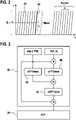
1 ein Blockdiagramm eines erfindungsgemäßen SA-Radarsensors;2 ein Zeitdiagramm einer von dem Radarsensor gesendeten Pulsfolge;3 ein Ablaufdiagramm für eine Chirp-Z-Transformation;4 ein Rekursionsschema zur Berechnung der Koeffizienten der Chirp-Z-Transformation; und5 ein Beispiel für ein modifiziertes Rekursionsschema.
1 a block diagram of an inventive SA radar sensor;2 a timing diagram of a pulse sequence transmitted by the radar sensor;3 a flowchart for a chirp z-transform;4 a recursion scheme for computing the chirp Z-transform coefficients; and5 an example of a modified recursion scheme.
Der in
Eine Analog-Digital-Wandlerstufe 16 bildet eine Schnittstelle zwischen dem Hochfrequenzteil 10 und einem Auswerteteil 18. Dort werden die digitalisierten komplexen Amplituden des Schwebungssignals in regelmäßigen Zeitintervallen abgetastet und als Zeitsignal gespeichert. Die Datenspeicherung erfolgt in einem zweidimensionalen Datenraum, d. h., die Amplituden A(n, k) werden als Funktionen eines „schnellen“ Index n und eines „langsamen“ Index k gespeichert.An analog-to-
In
Der Auswerteteil 18 (
Bei einem üblichen Rapid Chirp Radar (ohne SA-Auswertung) werden die im Abtastmodul aufgezeichneten Amplituden A(n, k) direkt an das FFT-Modul übermittelt. Das vom FFT-Modul erzeugte zweidimensionale Spektrum stellt dann ein Abstands-Geschwindigkeits-Radarbild 28 dar, in dem sich jedes Objekt 14 im Radarecho durch einen Peak 14' abzeichnet, dessen Lage in dem zweidimensionalen Abstands-Geschwindigkeits-Raum in den Abstand d des Objekts sowie dessen Relativgeschwindigkeit v angibt. Da die Frequenzrampen der Pulse 22 sehr steil sind, ist die aus der Relativbewegung der Objekte resultierende Dopplerverschiebung innerhalb eines Pulses vernachlässigbar, so dass die Lage des Peaks in der ersten Dimension in guter Näherung den Objektabstand d angibt. Die Relativgeschwindigkeit v des Objekts ergibt sich aus der Änderung der Phasen der Signale von Impuls zu Impuls, jeweils bei demselben Abtastzeitpunkt gemessen, und wird deshalb durch die Fouriertransformation in der zweiten Dimension erhalten.With a conventional rapid chirp radar (without SA evaluation), the amplitudes A(n, k) recorded in the sampling module are transmitted directly to the FFT module. The two-dimensional spectrum generated by the FFT module then represents a distance-
Bei dem hier beschriebenen SA-Radar sind die Objekte 14 jedoch nicht, zumindest nicht in erster Linie, vorausfahrende Fahrzeuge, deren Abstand und Relativgeschwindigkeit gemessen werden soll, sondern vielmehr in erster Linie stationäre Objekte am Fahrbahnrand, deren genaue Lage (Abstand und Winkel) gemessen werden soll. In
Aufgrund der scheinbaren Ortsveränderung des Objekts 14 während der Dauer eines Messzyklus kommt es jedoch zu Migrationseffekten, die zu einer Verzerrung des Abstands-Geschwindigkeits-Radarbildes 28 führen. Um diese Verzerrung zu korrigieren, ist zwischen dem Abtastmodul 20 und dem FFT-Modul 26 ein Transformationsmodul 32 eingefügt, das an den im Abtastmodul 20 aufgezeichneten Amplituden A(n, k) nach einem bestimmten Algorithmus, beispielsweise dem Keystone-Algorithmus, eine Transformation vornimmt, durch die die Migrationseffekte korrigiert werden. Das FFT-Modul 26 erhält somit als Eingangsdaten nicht unmittelbar die Amplituden A(n, k), sondern transformierte (migrationsfreie) Amplituden T(n, k). Außerdem findet im Transformationsmodul 32 bereits eine Fourier-Transformation in der Dimension statt, die der Abfolge der durch den Index k gezählten Pulse entspricht.Due to the apparent change in location of the
Die Transformation, die die Migrationseffekte korrigiert, ist definiert durch einen Satz von Koeffizienten c(n, k), die ihrerseits von den Indizes n und k abhängig sind.The transformation correcting for the migration effects is defined by a set of coefficients c(n,k), which in turn depend on the indices n and k.
Im Fall des Keystone-Algorithmus gilt beispielsweise:
Im Prinzip brauchen diese Koeffizienten c(n, k) für jedes Indexpaar n, k nur einmal berechnet um dann in einem Speicher des Auswerteteils 18 abgelegt zu werden. Allerdings benötigt man dann Speicherplatz für Nfast × Nslow (= 131072 im gezeigten Beispiel) komplexe Koeffizienten. Wenn der Radarsensor verschiedene Betriebsmodi aufweist, die sich beispielsweise in der Mittenfrequenz fc unterscheiden (z,B. um Interferenzen mit den Radarsensoren anderer Fahrzeuge auszuweichen), so vervielfacht sich der benötigte Speicherplatz entsprechend.In principle, these coefficients c(n, k) only need to be calculated once for each index pair n, k in order to then be stored in a memory of the
Wenn man andererseits jeden einzelnen Koeffizienten bei Bedarf nach der oben angegebenen Formel berechnet, so muss während jedes Messzyklus eine hohe Zahl sehr komplexer Berechnungen ausgeführt werden, so dass ein Rechner mit hoher Rechenkapazität benötigt wird.On the other hand, if one calculates each individual coefficient as required according to the formula given above, a large number of very complex calculations must be carried out during each measurement cycle, so that a computer with a high computing capacity is required.
Aus der oben angegebenen Formel (1) lässt sich jedoch die folgende Rekursionsformel ableiten:
Die Konstante D(k) braucht für jedes k nur einmal berechnet zu werden und kann dann gespeichert werden. Wenn man außerdem einen Anfangssatz von Koeffizienten
Man erreicht auf diese Weise einen günstigen Kompromiss zwischen Speicherbedarf und Rechenkapazität, so dass sich insgesamt die Kosten für die Hardware deutlich senken lassen.In this way, a favorable compromise is achieved between storage requirements and computing capacity, so that overall the costs for the hardware can be significantly reduced.
Wie
Die Arbeitsweise des Transformationsmoduls 32 ist in
Die in
Die Multiplikationen mit dem Phasenfaktor exp (i PSI) werden im Transformationsmodul 32 so vorgenommen, dass zunächst für einen festen Wert des Index n (beispielsweise n = 0) die Produkte für alle Werte des Index k berechnet werden und man dann zum nächsthöheren Wert des Index n übergeht. Das Koeffizientenmodul 34 kann dann die für die Berechnung der Phasenfaktoren benötigten Koeffizienten c(n, k) in der Reihenfolge liefern, in der sie für die Multiplikation mit dem Phasenfaktor benötigt werden. Auch in der FFT-Stufe 42 wird jeweils bei festem n über den Index k integriert. Die rekursive Berechnung der Koeffizienten im Koeffizientenmodul 34 braucht somit je Messzyklus nur einmal durchgeführt zu werden.The multiplications with the phase factor exp (i PSI) are carried out in the
Die Reihenfolge, in der die Berechnungen im Transformationsmodul 32 für die verschiedenen Werte von n durchgeführt werden, ist im Grunde beliebig. Es ist deshalb nicht zwingend, mit der Rekursion im Koeffizientenmodul 34 bei n = 0 zu beginnen. Beispielsweise könnte man auch bei einem Wert von n starten, der in der Nähe von Nfast/2 liegt, und dann mit zwei Rekursionsfolgen zu kleineren n und größeren n fortzuschreiten, wie in
Ein weiterer Vorteil dieser Vorgehensweise ergibt sich daraus, dass die transformierten Amplituden (T(n, k) im FFT-Modul 26 typischerweise mit einer Fensterfunktion multipliziert werden, die die Amplituden an den Rändern des betrachteten Zeitintervalls (bei n = 0 und n = Nfast) unterdrückt. Diese Fensterung dient dazu, Artefakte zu mildern, die sich daraus ergeben, dass die Transformation nur über ein endliches Zeitintervall ausgeführt werden kann. Wenn nun auch die Rekursion bei der Berechnung der Koeffizienten von der Mitte zu den Rändern des Zeitintervalls fortschreitet, ergibt sich der Vorteil, dass auch die akkumulierten Fehler an den Rändern des Intervalls durch die Fensterfunktion unterdrückt werden.A further advantage of this procedure results from the fact that the transformed amplitudes (T(n, k) in the
Eine Möglichkeit, die Fehlerakkumulation weiter zu unterdrücken, besteht darin, dass der Wertebereich der Indizes n in mehrere Blöcke aufgeteilt wird und dann die Rekursion blockweise vorgenommen wird, vorzugsweise wiederum von der Mitte zu den Rändern fortschreitend, wodurch sich eine weitere Verkürzung der Rekursionsfolgen ergibt.One way to further suppress the accumulation of errors is to divide the range of values of the indices n into several blocks and then perform the recursion in blocks, preferably again proceeding from the center to the edges, which results in a further reduction in the recursion sequences.
Daher sind die Rekursionsfolgen, die zu n = 128 bzw. zu n = 129 fortschreiten, kürzer als die Rekursionsfolgen, die zu den äußeren Rändern n = 0 und n = 255 fortschreiten. In der Mitte des Wertebereiches ergibt sich so eine geringere Fehlerakkumulation als an den äußeren Rändern, wo die Fehler durch die Fensterung noch zusätzlich unterdrückt werden.Therefore, the recursion sequences that proceed to n=128 and n=129, respectively, are shorter than the recursion sequences that proceed to the outer edges n=0 and n=255. In the middle of the value range, there is less error accumulation than at the outer edges, where the errors are additionally suppressed by the windowing.
Des Weiteren kann der Fehler auch dadurch verringert werden, dass anstelle des einen Satzes von Konstanten D(k) mehrere Sätze gespeichert werden, die für unterschiedliche Schrittgrößen, d.h. unterschiedliche Inkremente des Index n vorab exakt berechnet werden. Beispielsweise, kann ein Satz D_1 (k) für Inkrement der Länge 1 und ein zusätzlicher Satz D_10(k) für Inkremente der Länge 10 verwendet werden, sodass man jede zehnte Iteration mit D_10(k) berechnen kann, und die Iterationen dazwischen mit dem D_1 (k). Damit reduziert sich auch die Anzahl der Iterationen um Faktor 10. Die Anzahl der benutzten Sätze D_i(k) und deren Staffelung kann dabei beliebig gewählt werden und richtet sich nach Genauigkeitsbedarf, Zahlendarstellung und vorhandenem Speicher.Furthermore, the error can also be reduced by storing several sets instead of the one set of constants D(k), which are calculated exactly in advance for different step sizes, i.e. different increments of the index n. For example, a set D_1(k) for increments of
Claims (8)
Translated fromGermanPriority Applications (5)
| Application Number | Priority Date | Filing Date | Title |
|---|---|---|---|
| DE102021207032.9ADE102021207032A1 (en) | 2021-07-05 | 2021-07-05 | SA automotive radar sensor |
| US17/844,830US12282088B2 (en) | 2021-07-05 | 2022-06-21 | Sa radar sensor for motor vehicles |
| KR1020220080159AKR20230007234A (en) | 2021-07-05 | 2022-06-30 | Sa radar sensor for motor vehicles |
| JP2022107521AJP2023009006A (en) | 2021-07-05 | 2022-07-04 | Sa radar sensor for motor vehicles |
| CN202210791038.XACN115586519A (en) | 2021-07-05 | 2022-07-05 | SA radar sensor for motor vehicle |
Applications Claiming Priority (1)
| Application Number | Priority Date | Filing Date | Title |
|---|---|---|---|
| DE102021207032.9ADE102021207032A1 (en) | 2021-07-05 | 2021-07-05 | SA automotive radar sensor |
Publications (1)
| Publication Number | Publication Date |
|---|---|
| DE102021207032A1true DE102021207032A1 (en) | 2023-01-05 |
Family
ID=84493029
Family Applications (1)
| Application Number | Title | Priority Date | Filing Date |
|---|---|---|---|
| DE102021207032.9APendingDE102021207032A1 (en) | 2021-07-05 | 2021-07-05 | SA automotive radar sensor |
Country Status (5)
| Country | Link |
|---|---|
| US (1) | US12282088B2 (en) |
| JP (1) | JP2023009006A (en) |
| KR (1) | KR20230007234A (en) |
| CN (1) | CN115586519A (en) |
| DE (1) | DE102021207032A1 (en) |
Families Citing this family (1)
| Publication number | Priority date | Publication date | Assignee | Title |
|---|---|---|---|---|
| KR20240052377A (en)* | 2022-10-14 | 2024-04-23 | 삼성전자주식회사 | Method and apparatus for predicting movement of cut-in vehicle |
Family Cites Families (22)
| Publication number | Priority date | Publication date | Assignee | Title |
|---|---|---|---|---|
| US4016567A (en)* | 1974-06-24 | 1977-04-05 | Texas Instruments Incorporated | CCD range-doppler processor |
| FR2358061A1 (en)* | 1976-07-08 | 1978-02-03 | Ibm France | EQUALIZATION METHOD AND DEVICE USING THE FOURIER TRANSFORM |
| JPS56136529A (en)* | 1980-03-28 | 1981-10-24 | Tokyo Shibaura Electric Co | Apparatus for reconstituting image |
| US4471357A (en)* | 1981-10-26 | 1984-09-11 | The United States Of America As Represented By The Administrator Of The National Aeronautics And Space Administration | Pipelined digital SAR azimuth correlator using hybrid FFT/transversal filter |
| US4931977A (en)* | 1987-10-30 | 1990-06-05 | Canadian Marconi Company | Vectorial adaptive filtering apparatus with convergence rate independent of signal parameters |
| US4876549A (en)* | 1988-03-07 | 1989-10-24 | E-Systems, Inc. | Discrete fourier transform direction finding apparatus |
| US6131071A (en)* | 1996-12-06 | 2000-10-10 | Bp Amoco Corporation | Spectral decomposition for seismic interpretation |
| EP1110155A1 (en)* | 1998-09-03 | 2001-06-27 | Conexant Systems, Inc. | A method of frequency domain filtering employing a real to analytic transform |
| CN1333618A (en)* | 2000-07-18 | 2002-01-30 | 日本胜利株式会社 | Recursion type discrete Fourier transformer |
| WO2006103486A1 (en)* | 2005-03-31 | 2006-10-05 | Nokia Corporation | Method and device for correlation detection in spread spectrum transmission systems by fast fourier transformation |
| KR100747552B1 (en)* | 2006-11-22 | 2007-08-08 | 한국전자통신연구원 | Apparatus and Method for Initial Coefficient Acquisition of Decision Feedback Equalizer Using FFT |
| JP5850216B2 (en)* | 2010-04-13 | 2016-02-03 | ソニー株式会社 | Signal processing apparatus and method, encoding apparatus and method, decoding apparatus and method, and program |
| IL206008A0 (en)* | 2010-05-27 | 2011-02-28 | Amir Meir Zilbershtain | Transmit receive interference cancellation |
| US8812571B2 (en)* | 2011-05-12 | 2014-08-19 | Telefonaktiebolaget L M Ericsson (Publ) | Spectrum agile radio |
| US20160370484A1 (en)* | 2014-03-05 | 2016-12-22 | Cgg Services Sa | Systems and methods to reduce noise in seismic data using a frequency dependent calendar filter |
| KR101809371B1 (en)* | 2016-07-29 | 2017-12-14 | 전자부품연구원 | RadCom System and Method using a Fast Chirp Signal for Vehicle |
| US10768328B2 (en)* | 2017-01-12 | 2020-09-08 | Pgs Geophysical As | Seismic noise attenuation using dip map data structure |
| JP6724828B2 (en)* | 2017-03-15 | 2020-07-15 | カシオ計算機株式会社 | Filter calculation processing device, filter calculation method, and effect imparting device |
| EP3471271A1 (en)* | 2017-10-16 | 2019-04-17 | Acoustical Beauty | Improved convolutions of digital signals using a bit requirement optimization of a target digital signal |
| IL259190A (en)* | 2018-05-07 | 2018-06-28 | Arbe Robotics Ltd | System and method of fmcw time multiplexed mimo imaging radar using multi-band chirps |
| US11852750B2 (en)* | 2019-06-28 | 2023-12-26 | Smart Radar System, Inc. | Method and apparatus for radar signal processing using recurrent neural network |
| US11835649B2 (en)* | 2019-06-28 | 2023-12-05 | Smart Radar System, Inc. | Method and apparatus for radar signal processing using convolutional neural network |
- 2021
- 2021-07-05DEDE102021207032.9Apatent/DE102021207032A1/enactivePending
- 2022
- 2022-06-21USUS17/844,830patent/US12282088B2/enactiveActive
- 2022-06-30KRKR1020220080159Apatent/KR20230007234A/enactivePending
- 2022-07-04JPJP2022107521Apatent/JP2023009006A/enactivePending
- 2022-07-05CNCN202210791038.XApatent/CN115586519A/enactivePending
Also Published As
| Publication number | Publication date |
|---|---|
| US20230003873A1 (en) | 2023-01-05 |
| US12282088B2 (en) | 2025-04-22 |
| CN115586519A (en) | 2023-01-10 |
| KR20230007234A (en) | 2023-01-12 |
| JP2023009006A (en) | 2023-01-19 |
Similar Documents
| Publication | Publication Date | Title |
|---|---|---|
| DE102018102816B3 (en) | RADAR WITH PHASE CORRECTION | |
| EP0795762B1 (en) | Method for azimuth scaling for SAR-data and high precision processor for two-dimensional processing of scan-SAR data | |
| EP1554602B1 (en) | Method for measuring distances and speeds of several objects by means of an fmcw radar | |
| DE19757309C1 (en) | Process for processing Spotlight SAR raw data | |
| DE112007003175B4 (en) | Electronically scanning radar system | |
| DE102019112469A1 (en) | RESOLUTION OF DOPPLER AMBIGUITIES IN A MULTI-INPUT-MULTI-OUTPUT RADAR USING DIGITAL MULTIPLE-PULSE SEQUENCE FREQUENCIES | |
| DE4122592C1 (en) | ||
| DE102016221947A1 (en) | Radar sensor for motor vehicles | |
| EP1296157B1 (en) | Method for calibrating radar signals from the sub-apertures of the antenna of a two-channel SAR/MTI radar system | |
| DE4427657A1 (en) | Two=dimensional data processing image generation, e.g. for azimuth and distance measurement | |
| DE102020210079B3 (en) | Radar method and radar system with high range resolution with little signal processing effort | |
| EP3385750A1 (en) | Method and device for processing raw sar data | |
| DE102012021212A1 (en) | Method for detecting interference in a received signal of a radar sensor, driver assistance device and motor vehicle | |
| DE69026583T2 (en) | Radar with synthetic aperture and beam sharpening ability in the direction of travel | |
| EP3752852B1 (en) | Estimation of cartesian velocity of extended radar objects with a radar sensor | |
| DE102017223429A1 (en) | Method and device for object detection by means of radar | |
| EP4196818B1 (en) | Method and device for determining frequency disturbances in a received signal of an active multi-channel sar system | |
| DE112020005888T5 (en) | RADAR EQUIPMENT, OBSERVATION TARGET DETECTION METHOD AND IN-VEHICLE EQUIPMENT | |
| DE102018202864A1 (en) | Method and system for synthetic aperture radar signal processing | |
| DE102021213495A1 (en) | radar measurement method | |
| DE102021207032A1 (en) | SA automotive radar sensor | |
| WO2016206841A1 (en) | Method for operating a radar device | |
| DE102020211347A1 (en) | Radar system and method of operating a radar system | |
| DE102018203333A1 (en) | Method for unambiguously determining the speed of an object on a RADAR measuring system | |
| EP1184680B1 (en) | Method for repositioning of moving targets in SAR-images |