DE102021119629B3 - Input unit for a medical instrument and medical system with an input unit - Google Patents
Input unit for a medical instrument and medical system with an input unitDownload PDFInfo
- Publication number
- DE102021119629B3 DE102021119629B3DE102021119629.9ADE102021119629ADE102021119629B3DE 102021119629 B3DE102021119629 B3DE 102021119629B3DE 102021119629 ADE102021119629 ADE 102021119629ADE 102021119629 B3DE102021119629 B3DE 102021119629B3
- Authority
- DE
- Germany
- Prior art keywords
- tool
- rotating element
- input unit
- control unit
- rotation
- Prior art date
- Legal status (The legal status is an assumption and is not a legal conclusion. Google has not performed a legal analysis and makes no representation as to the accuracy of the status listed.)
- Active
Links
- 238000005096rolling processMethods0.000claimsdescription20
- 238000006243chemical reactionMethods0.000claimsdescription4
- 230000001960triggered effectEffects0.000claims1
- 238000011161developmentMethods0.000description11
- 230000018109developmental processEffects0.000description11
- 230000007246mechanismEffects0.000description4
- 230000004913activationEffects0.000description2
- 230000008878couplingEffects0.000description2
- 238000010168coupling processMethods0.000description2
- 238000005859coupling reactionMethods0.000description2
- 230000001419dependent effectEffects0.000description2
- 238000013461designMethods0.000description2
- 239000012636effectorSubstances0.000description2
- 238000013507mappingMethods0.000description2
- 230000000284resting effectEffects0.000description2
- 101100116570Caenorhabditis elegans cup-2 geneProteins0.000description1
- 101100116572Drosophila melanogaster Der-1 geneProteins0.000description1
- 230000003213activating effectEffects0.000description1
- 239000013013elastic materialSubstances0.000description1
- 239000013536elastomeric materialSubstances0.000description1
- 230000000968intestinal effectEffects0.000description1
- 238000002372labellingMethods0.000description1
- 239000000463materialSubstances0.000description1
- 238000000034methodMethods0.000description1
- 238000004091panningMethods0.000description1
- 230000035479physiological effects, processes and functionsEffects0.000description1
- 230000008092positive effectEffects0.000description1
- 230000008569processEffects0.000description1
- 238000009420retrofittingMethods0.000description1
- 239000000523sampleSubstances0.000description1
- 239000000725suspensionSubstances0.000description1
- 230000009466transformationEffects0.000description1
- 238000013519translationMethods0.000description1
Images


Classifications
- A—HUMAN NECESSITIES
- A61—MEDICAL OR VETERINARY SCIENCE; HYGIENE
- A61B—DIAGNOSIS; SURGERY; IDENTIFICATION
- A61B34/00—Computer-aided surgery; Manipulators or robots specially adapted for use in surgery
- A61B34/70—Manipulators specially adapted for use in surgery
- A—HUMAN NECESSITIES
- A61—MEDICAL OR VETERINARY SCIENCE; HYGIENE
- A61B—DIAGNOSIS; SURGERY; IDENTIFICATION
- A61B34/00—Computer-aided surgery; Manipulators or robots specially adapted for use in surgery
- A61B34/70—Manipulators specially adapted for use in surgery
- A61B34/71—Manipulators operated by drive cable mechanisms
- A—HUMAN NECESSITIES
- A61—MEDICAL OR VETERINARY SCIENCE; HYGIENE
- A61B—DIAGNOSIS; SURGERY; IDENTIFICATION
- A61B17/00—Surgical instruments, devices or methods
- A61B2017/00973—Surgical instruments, devices or methods pedal-operated
Landscapes
- Health & Medical Sciences (AREA)
- Surgery (AREA)
- Engineering & Computer Science (AREA)
- Life Sciences & Earth Sciences (AREA)
- Biomedical Technology (AREA)
- Robotics (AREA)
- Nuclear Medicine, Radiotherapy & Molecular Imaging (AREA)
- Heart & Thoracic Surgery (AREA)
- Medical Informatics (AREA)
- Molecular Biology (AREA)
- Animal Behavior & Ethology (AREA)
- General Health & Medical Sciences (AREA)
- Public Health (AREA)
- Veterinary Medicine (AREA)
- Manipulator (AREA)
Abstract
Translated fromGermanDescription
Translated fromGermanDie vorliegende Erfindung betrifft eine Eingabeeinheit zum Betreiben eines medizinischen Instruments nach dem Oberbegriff des Anspruchs 1. Ferner betrifft die vorliegende Erfindung ein medizinisches System mit zumindest einer erfindungsgemäßen Eingabeeinheit und zumindest einem medizinischen Instrument.The present invention relates to an input unit for operating a medical instrument according to the preamble of claim 1. The present invention also relates to a medical system having at least one input unit according to the invention and at least one medical instrument.
Eine gattungsbildende Eingabeeinheit zum Betreiben eines medizinischen Instruments ist beispielsweise aus der
Das bekannte medizinische Instrument umfasst einen hohlen, sich entlang einer Längsachse erstreckenden Schaft zum Aufnehmen von Lenkdrähten, wobei der Schaft distalseitig ein entlang einer Erstreckungsachse ausgebildetes Werkzeug und proximalseitig eine Steuereinheit aufweist, die zum Manipulieren des Werkzeugs mittels der Lenkdrähte ausgebildet ist. Die Steuereinheit weist eine räumlich verstellbare Scheibe auf, die mit vier Lenkdrähten gekoppelt ist und über distalseitig angeordnete Schwenkglieder das Werkzeug relativ zur Längsachse verschwenken kann.The known medical instrument comprises a hollow shaft extending along a longitudinal axis for receiving steering wires, the shaft having a tool formed along an axis of extent on the distal side and a control unit on the proximal side, which is formed for manipulating the tool using the steering wires. The control unit has a spatially adjustable disc which is coupled to four steering wires and can pivot the tool relative to the longitudinal axis via pivoting members arranged on the distal side.
Für die Steuerung der Manipulation des medizinischen Instruments ist eine gattungsbildende Eingabeeinheit mit ersten Eingabemitteln vorgesehen, die sich mittels der Hand einer Bedienperson bedienen lassen. Somit werden ergonomische Benutzereingaben der Bedienperson kontinuierlich, also schwenk- und/oder rotationsgetreu in die Manipulation des Werkzeugs umgesetzt. Neben dem reinen Verschwenken des Werkzeugs zum Beeinflussen der Ausrichtung kann das Werkzeug zudem über mit dem Zeigefinger der Bedienperson zusammenwirkende Bedienmittel zusätzlich manipuliert werden, um beispielsweise ein als Maulteil ausgebildetes Werkzeug zwischen einem offenen und einem geschlossenen Zustand zu verstellen. Ferner ist eine begrenzte Rotation des Werkzeugs durch das Rotieren der gegriffenen Eingabeeinheit umsetzbar, wobei die Rotation durch die natürliche Bewegungsfreiheit der Hand und/oder des Arms der Bedienperson abgebildet wird.For controlling the manipulation of the medical instrument, a generic input unit with first input means is provided, which can be operated by an operator's hand. Ergonomic user inputs from the operator are thus converted continuously, that is to say true to pan and/or rotation, to the manipulation of the tool. In addition to simply pivoting the tool to influence the orientation, the tool can also be manipulated using operating means interacting with the index finger of the operator, for example to adjust a tool designed as a jaw part between an open and a closed state. Furthermore, a limited rotation of the tool can be implemented by rotating the gripped input unit, the rotation being represented by the natural freedom of movement of the operator's hand and/or arm.
Bei der Steuerung des medizinischen Instruments folgen die Verstellbewegungen des Werkzeugs somit stets den natürlichen Bewegungen der Hand bzw. des Arms der Bedienperson und zwar in einer ununterbrochenen und/oder absoluten Weise. Mit anderen Worten folgt das mechanisch gekoppelte Werkzeug den ergonomisch begrenzten Benutzereingaben der Bedienperson kontinuierlich, damit die Bedienperson stets die Kontrolle über das Werkzeug besitzt und somit ein präzises Arbeiten im operativen Einsatz ermöglicht wird.When controlling the medical instrument, the adjustment movements of the tool always follow the natural movements of the operator's hand or arm, specifically in an uninterrupted and/or absolute manner. In other words, the mechanically coupled tool continuously follows the operator's ergonomically limited user inputs so that the operator is always in control of the tool and precise work is thus made possible during operational use.
Die gattungsbildenden Eingabeeinheiten ermöglichen hierdurch die präzise Durchführung von minimalinvasiven medizinischen Operationen, um beispielsweise Gewebeproben zu entnehmen, Gewebe zu vernähen oder andere operative Aktionen im sensiblen Umfeld auszuführen.As a result, the generic input units enable the precise implementation of minimally invasive medical operations, for example in order to take tissue samples, sew up tissue or carry out other operational actions in a sensitive environment.
Nachteilig bei der bekannten Eingabeeinheit ist die begrenzte und/oder eingeschränkte Manipulation des Werkzeugs, da es zu einer schwenk- und rotationsgetreuen Abbildung der natürlichen Benutzerbewegung kommt, weshalb es zusätzlich zu der mechanischen und/oder konstruktiven Beschränkung des Werkzeugs zu einer Einschränkung aufgrund des Grads der natürlichen Bewegungsfreiheit der Bedienperson kommt.A disadvantage of the known input unit is the limited and/or restricted manipulation of the tool, since the natural user movement is reproduced with pan and rotation accuracy, which is why, in addition to the mechanical and/or structural limitation of the tool, there is a limitation due to the degree of natural freedom of movement of the operator.
Ferner sind auch medizinische Instrumente bekannt, die mittels einer Spindel ein bereichsweises mechanisch begrenztes Rotieren des Werkzeugs für einen begrenzten Rotationsbereich ermöglichen. Für die Steuerung werden Eingabeeinheiten eingesetzt, die eine rotationsgetreue Steuerung des Werkzeugs ermöglichen, wobei es zum Überwinden der eingeschränkten Bewegungsfreiheit der Bedienperson zu einer Unterbrechung in der Steuerung kommt, indem die Bedienperson die ersten Eingabemittel umgreift oder es zu einer kurzzeitigen Unterbrechung und/oder Entkopplung zwischen der Eingabeeinheit und dem Werkzeug für ein Zurückstellen und/oder Rückführen der ersten Eingabemittel kommt, was immer mit einem kurzzeitigen Kontrollverlust über das Werkzeug verbunden ist.Furthermore, medical instruments are also known which, by means of a spindle, enable the tool to rotate in a mechanically limited manner in some areas for a limited range of rotation. Input units are used for the control, which enable the tool to be controlled in a rotation-accurate manner, with the control being interrupted in order to overcome the restricted freedom of movement of the operator, in that the operator grips the first input means, or there is a brief interruption and/or decoupling between the input unit and the tool for resetting and/or returning the first input means, which is always associated with a momentary loss of control over the tool.
Ferner existiert zwischenzeitlich eine vielversprechende Weiterentwicklung des beschriebenen medizinischen Instruments, die in der
Die
Die
Die
Der vorliegenden Erfindung liegt daher die Aufgabe zugrunde, eine Eingabeeinheit vorzuschlagen, die die aus dem Stand der Technik bekannten Nachteile überwindet. Insbesondere ist es Aufgabe der vorliegenden Erfindung eine Eingabeeinheit anzugeben, die trotz des kontinuierlichen, schwenk- und/oder rotationsgetreuen Umsetzens einer Benutzereingabe die Steuerung einer endlosen Rotation des Werkzeugs ermöglicht.The present invention is therefore based on the object of proposing an input unit which overcomes the disadvantages known from the prior art. In particular, it is the object of the present invention to specify an input unit which, despite the continuous, pivoting and/or rotation-accurate conversion of a user input, makes it possible to control an endless rotation of the tool.
Ferner besteht die Aufgabe darin, ein medizinisches System mit zumindest einer erfindungsgemäßen Eingabeeinheit und zumindest einem medizinischen Instrument anzugeben.Furthermore, the object consists in specifying a medical system with at least one input unit according to the invention and at least one medical instrument.
Diese Aufgabe wird durch eine Eingabeeinheit mit den Merkmalen des Anspruchs 1 gelöst. Ferner wird die Aufgabe durch ein erfindungsgemäßes medizinisches System gelöst.This object is achieved by an input unit having the features of claim 1. Furthermore, the object is achieved by a medical system according to the invention.
Vorteilhafte Weiterbildungen der Erfindung sind in den abhängigen Ansprüchen angegeben. In den Rahmen der Erfindung fallen sämtliche Kombinationen aus zumindest zwei von in der Beschreibung, den Ansprüchen und/oder den Figuren offenbarten Merkmalen.Advantageous developments of the invention are specified in the dependent claims. All combinations of at least two of the features disclosed in the description, the claims and/or the figures fall within the scope of the invention.
Im Rahmen der vorliegenden Erfindung ist es vorgesehen eine Eingabeeinheit mit ersten Eingabemitteln und zweiten Eingabemitteln anzugeben. Die erfindungsgemäße Eingabeeinheit ist zum Betreiben eines medizinischen Instruments mit einem hohlen, sich entlang einer Längsachse erstreckenden Schaft zum Aufnehmen von Lenkdrähten ausgebildet, wobei an einem ersten oder distalseitigen Ende des Schafts ein Werkzeug angeordnet ist, das sich entlang einer Erstreckungsachse erstreckt. Ferner ist an einem zweiten oder proximalseitigen Ende des Schafts eine Steuereinheit zum Manipulieren des Werkzeugs mittels der Lenkdrähte vorgesehen.An input unit with first input means and second input means is provided within the scope of the present invention. The input unit according to the invention is designed for operating a medical instrument with a hollow shaft extending along a longitudinal axis for receiving guide wires, with a tool being arranged at a first or distal end of the shaft, which extends along an axis of extension. Furthermore, a control unit for manipulating the tool by means of the steering wires is provided at a second or proximal end of the shaft.
Die erfindungsgemäßen ersten Eingabemittel sind zum kontinuierlichen, schwenk- und/oder rotationsgetreuen Umsetzen einer ergonomisch begrenzten Benutzereingabe einer Bedienperson in eine Verstellbewegung des Werkzeugs in einem ersten Handhabungsmodus ausgebildet, um das Werkzeug durch die ersten Eingabemittel mittels der Lenkdrähte über die Steuereinheit relativ zur Längsachse zu verschwenken und/oder um die Erstreckungsachse zu rotieren. Aufgrund der baulichen Ausgestaltung des bereichsweise starr ausgebildeten Schafts ist eine Schwenkung des Werkzeugs in Bezug auf die Längserstreckung des Schafts nur über einen begrenzten Schwenkbereich möglich. Ferner ist auch das Rotieren des Werkzeugs nur über einen begrenzten Rotationsbereich möglich, der durch die natürliche Beweglichkeit der Bedienperson, insbesondere einer erste Bedienmittel greifenden Hand der Bedienperson, die dann in Bezug auf die kontinuierliche, also absolute Einbringung einer Rotation aufgrund des Aufbaus des menschlichen Arms in Bezug auf den Rotationsbereich begrenzt ist.The first input means according to the invention are designed for the continuous, pivoting and/or rotationally accurate conversion of an ergonomically limited user input from an operator into an adjustment movement of the tool in a first handling mode, in order to pivot the tool relative to the longitudinal axis using the first input means using the steering wires via the control unit and/or rotate about the axis of extension. Due to the structural design of the shank, which is designed to be rigid in some areas, a pivoting of the tool in relation to the longitudinal extension of the shank is only possible over a limited pivoting range. Furthermore, the rotation of the tool is only possible over a limited range of rotation, which is due to the natural mobility of the operator, in particular a hand of the operator gripping the first operating means, which then in relation to the continuous, i.e. absolute introduction of a rotation due to the structure of the human arm is limited in terms of range of rotation.
Bevorzugt sind als erste Eingabemittel erste Bedienmittel für das Manipulieren des Werkzeugs vorgesehen, die kontinuierlich, also ohne Unterbrechung in der Kopplung zwischen den ersten Bedienmitteln und dem Werkzeug, eine Übersetzung, Umsetzung und/oder Umformung der ergonomisch begrenzten Benutzereingabe in die Manipulation des Werkzeugs abbilden.First operating means for manipulating the tool are preferably provided as the first input means, which continuously, i.e. without interruption in the coupling between the first operating means and the tool, map a translation, conversion and/or transformation of the ergonomically limited user input into the manipulation of the tool.
Bei den ersten Bedienmitteln handelt es sich bevorzugt um einen Joystick, ein Gimbal, ein kardanisch aufgehängtes Bedienelement, ein kardanisch aufgehängtes Druckelement oder eine gleichwertige Eingabeeinheit zum Erfassen von natürlichen Raumbewegungen der Bedienperson in allen Raumrichtungen. Anders ausgedrückt, die ersten Eingabemittel, insbesondere die ersten Bedienmittel, sind so ausgestaltet, dass Bewegungen in sämtlichen Freiheitsgraden erfassbar sind und im ersten Handhabungsmodus schwenk- und/oder rotationsgetreu, bevorzugt schwenk- und/oder rotationsähnlich, in jedem Fall jedoch kontinuierlich auf das Werkzeug übertragbar sind.The first operating means is preferably a joystick, a gimbal, a gimballed operating element, a gimbaled pressure element or an equivalent input unit for detecting natural spatial movements of the operator in all spatial dimensions ments. In other words, the first input means, in particular the first operating means, are designed in such a way that movements can be detected in all degrees of freedom and in the first handling mode are true to pivot and/or rotation, preferably similar to pivot and/or rotation, but in any case continuously to the tool are transferrable.
Besonders bevorzugt sind die ersten Eingabemittel zum ununterbrochenen und/oder absoluten Umsetzen der ergonomisch begrenzten Benutzereingabe, insbesondere einer natürlichen Benutzerbewegung von bewegbaren ersten Bedienmitteln, ausgebildet.The first input means are particularly preferably designed for the uninterrupted and/or absolute implementation of the ergonomically limited user input, in particular a natural user movement of movable first operating means.
Die zweiten Eingabemittel, die zum zumindest abschnittsweisen, nicht absoluten Umsetzen wenigstens einer weiteren Benutzereingabe in eine endlose Rotationsbewegung des Werkzeugs in dem zweiten Handhabungsmodus ausgebildet sind, sind erfindungsgemäß durch eine Fußbedieneinheit ausgebildet, die ein mit dem Fuß der Bedienperson bedien- und/oder steuerbares Rotierelement zum Erfassen und Umsetzen der weiteren Benutzereingabe aufweist.The second input means, which are designed for at least partially, non-absolutely converting at least one further user input into an endless rotational movement of the tool in the second handling mode, are designed according to the invention by a foot control unit, which is a rotating element that can be operated and/or controlled with the foot of the operator for detecting and converting the further user input.
Bei der vorliegenden erfindungsgemäßen Ausgestaltung der zweiten Eingabemittel als Fußbedieneinheit ist besonders vorteilhaft, dass sich gattungsbildende Eingabeeinheiten zum Betreiben von medizinischen Instrumenten im ersten Handhabungsmodus um die zusätzliche Steuerung des Werkzeugs im zweiten Handhabungsmodus nachrüsten und somit erweitern lassen. Somit wird es vorteilhaft ermöglicht, dass nach einem Austausch des medizinischen Instruments und somit der Erweiterung des umfassten Werkzeugs um die Fähigkeit der endlosen Rotation, die bisherigen ersten Eingabemittel mit der erfindungsgemäßen Fußbedieneinheit ergänzt werden. Neben der grundsätzlichen Möglichkeit der Nachrüstbarkeit, was sich positiv auf etwaige Investitionskosten auswirkt, führt dies auch zu einer breiteren Akzeptanz entsprechender Systeme, da die Umstellung des geschulten Bedienpersonals vom Steuern des Werkzeugs nur im ersten Handhabungsmodus auf das Steuern des Werkzeugs im ersten Handhabungsmodus und im zweiten Handhabungsmodus als leicht aufgefasst wird.In the present inventive embodiment of the second input means as a foot control unit, it is particularly advantageous that generic input units for operating medical instruments in the first handling mode can be retrofitted and thus expanded to include the additional control of the tool in the second handling mode. It is thus advantageously possible that after the medical instrument has been exchanged and the included tool has been expanded to include the capability of endless rotation, the previous first input means can be supplemented with the foot control unit according to the invention. In addition to the fundamental possibility of retrofitting, which has a positive effect on any investment costs, this also leads to a broader acceptance of corresponding systems, since the trained operating personnel can switch from controlling the tool only in the first handling mode to controlling the tool in the first handling mode and in the second Handling mode is perceived as easy.
Weiterbildend ist es vorgesehen, dass das Rotierelement zum Steuern einer nach links gerichteten Rotationsbewegung des Werkzeugs in die linke Richtung rotierbar ist und zum Steuern einer nach rechts gerichteten Rotationsbewegung des Werkzeugs in die rechte Richtung rotierbar ist. Vorteilhaft realisiert eine derartige Implementierung und/oder Umsetzung der Richtungseingabe der endlosen Rotationsrichtung eine besonders intuitive Steuerung des Werkzeugs im zweiten Handhabungsmodus, weshalb zusätzlich die Hürde und/oder der Aufwand zur zusätzlichen Steuerung des zweiten Handhabungsmodus für die Bedienperson als gering ausfallen.In a further development, it is provided that the rotating element can be rotated in the left direction to control a rotational movement of the tool directed to the left and in the right direction to control a rotational movement of the tool directed to the right. Such an implementation and/or implementation of the direction input of the endless direction of rotation advantageously realizes a particularly intuitive control of the tool in the second handling mode, which is why the hurdle and/or the effort for additional control of the second handling mode for the operator is also low.
Weiterbildend ist es vorgesehen, dass das Rotierelement als ein zylinderförmiges Rollelement ausgebildet ist und eine Längserstreckung zwischen 5cm bis 30cm, bevorzugt zwischen 5cm bis 25cm, weiter bevorzugt zwischen 5cm bis 20cm umfasst.In a further development, it is provided that the rotating element is designed as a cylindrical rolling element and has a longitudinal extent of between 5 cm and 30 cm, preferably between 5 cm and 25 cm, more preferably between 5 cm and 20 cm.
Vorteilhaft ermöglicht die Ausgestaltung des Rotierelements als zylinderförmiges Rollelement ein einfaches und sicheres Bedienen und/oder Steuern des Rollelements mit dem Fuß, da durch die Längserstreckung des Rollelements unabhängig von einer genauen Sitzposition der Bedienperson, der Schuhgröße und/oder der Schuhwahl eine ergonomische Bedienung bzw. Steuerung des zu rotierenden Rollelements ermöglicht wird.Advantageously, the configuration of the rotating element as a cylindrical rolling element enables simple and safe operation and/or control of the rolling element with the foot, since the longitudinal extension of the rolling element allows ergonomic operation or Control of the rolling element to be rotated is made possible.
In einer Weiterbildung der vorliegenden Erfindung ist das Rotierelement aus einer Ruhestellung entlang einer rechten oder ersten Rotationsrichtung in einen rechten Endanschlag und/oder eine erste Stellposition und/oder entlang einer linken oder zweiten Rotationsrichtung in einen linken Endanschlag und/oder zweite Stellposition rotierbar, derartig, dass in dem/der rechten Endanschlag und/oder ersten Stellposition eine nach rechts gerichtete endlose Rotationsbewegung des Werkzeugs aktivierbar ist und dass in dem/der linken Endanschlag bzw. zweiten Stellposition eine nach links gerichtete endlose Rotationsbewegung des Werkzeugs aktivierbar ist.In a further development of the present invention, the rotating element can be rotated from a rest position along a right-hand or first direction of rotation into a right-hand end stop and/or a first setting position and/or along a left-hand or second direction of rotation into a left-hand end stop and/or second setting position, such that in the right end stop and/or first setting position a rightward endless rotational movement of the tool can be activated and that in the left end stop or second setting position a leftward endless rotational movement of the tool can be activated.
Zunächst ermöglicht eine übereinstimmende Rotationsrichtung zwischen dem Rotierelement und dem Werkzeug eine intuitive Steuerung des Werkzeugs im zweiten Handhabungsmodus. Ferner wird durch die Aktivierung der endlosen oder dauerhaften Rotationsbewegung des Werkzeugs durch das Rotieren des Rotierelements in den rechten bzw. linken Endanschlag das Bedienen des Rotierelements erleichtert, da zum Einbringen von länger andauernden Rotationsbewegungen das Rotierelement nicht mehrfach mit dem Fuß abgestrichen bzw. in eine Rotationsbewegung versetzt werden muss.Firstly, a matching direction of rotation between the rotating element and the tool enables intuitive control of the tool in the second handling mode. Furthermore, the activation of the endless or permanent rotary movement of the tool by rotating the rotary element into the right or left end stop makes it easier to operate the rotary element, since the rotary element does not have to be repeatedly wiped off with the foot or in a rotary movement to introduce longer-lasting rotary movements must be transferred.
Ferner ist es im Rahmen einer Weiterbildung der Erfindung geplant, dass das Rotierelement wenigstens einen ersten Druckschalter umfasst, wobei das Rotierelement so ausgebildet ist, dass beim Erreichen des rechten Endanschlags bzw. der ersten Stellposition der erste Druckschalter durch das Rotierelement betätigbar und/oder aktivierbar ist und dass beim Erreichen des linken Endanschlags bzw. der zweiten Stellposition der erste Druckschalter oder ein weiterer Druckschalter durch das Rotierelement betätigbar und/oder aktivierbar ist.Furthermore, it is planned as part of a development of the invention that the rotating element comprises at least one first pressure switch, the rotating element being designed in such a way that the first pressure switch can be actuated and/or activated by the rotating element when the right-hand end stop or the first setting position is reached and that when the left end stop or the second setting position is reached, the first pressure switch or another pressure switch is activated the rotating element can be actuated and/or activated.
In diesem Zusammenhang ist es besonders bevorzugt, wenn der erste Druckschalter und/oder der weitere Druckschalter als ein Taster ausgebildet ist, um das Aktivieren der endlosen oder dauerhaften Rotationsbewegung des Werkzeugs einfach umzusetzen.In this context, it is particularly preferred if the first pressure switch and/or the further pressure switch is designed as a button in order to simply implement the activation of the endless or permanent rotational movement of the tool.
Ferner ist es weiterbildend vorgesehen, dass das Rotierelement beim Rotieren in die rechte Richtung nicht nur in eine erste Stellposition rotierbar ist, sondern zusätzlich in der gleichen Richtung schrittweise in weitere Stellpositionen verstellbar ist. Vorteilhaft ermöglicht dies neben dem bloßen Aktivieren der Rotationsbewegung zusätzlich auch die Rotationsgeschwindigkeit des Werkzeugs oder einen zu rotierenden Winkelbereich im zweiten Handhabungsmodus standardisiert vorzugeben. Entsprechendes gilt natürlich auch für das Rotieren in die linke Richtung, wobei dann auch hier eine Auswahl der Rotationsgeschwindigkeit und/oder des Winkelbereichs durch weitere Stellpositionen implementierbar sein soll.Furthermore, it is provided in a further development that the rotating element, when rotating in the right direction, can not only be rotated into a first setting position, but can also be gradually adjusted into further setting positions in the same direction. In addition to simply activating the rotational movement, this advantageously also allows the rotational speed of the tool or an angular range to be rotated to be specified in a standardized manner in the second handling mode. Of course, the same also applies to rotating in the left direction, in which case a selection of the rotational speed and/or the angular range should then also be able to be implemented here by means of further adjustment positions.
Weiterbildend umfasst die Fußbedieneinheit eine keilförmige Gehäuseeinheit mit einer abgeschrägten Oberseite, wobei in einem Betriebszustand der Fußbedieneinheit die Fußbedieneinheit auf einem Untergrund, insbesondere auf dem Raumboden, so abgestellt und/oder angeordnet ist, dass die abgeschrägte Oberseite in Richtung der Bedienperson ausgerichtet ist.In a further development, the foot control unit comprises a wedge-shaped housing unit with a slanted upper side, wherein in an operating state of the foot control unit the foot control unit is set down and/or arranged on a surface, in particular on the floor of the room, in such a way that the slanted upper side is aligned in the direction of the operator.
Vorteilhaft ermöglicht eine entsprechende Ausgestaltung und/oder Ausrichtung ein ergonomisches Bedienen des Rotierelements durch den auf dem Untergrund abgestellten Fuß der Bedienperson, wobei dann die Fußverse auf dem Untergrund abstellbar ist und ein Bedienen der Fußbedieneinheit mit dem Fußballen ermöglicht wird, um eine Rotationsbewegung in das Rotierelement einzubringen.A corresponding configuration and/or alignment advantageously enables ergonomic operation of the rotating element by the operator's foot placed on the ground, in which case the heel of the foot can be placed on the ground and the foot control unit can be operated with the ball of the foot in order to cause a rotational movement in the rotating element bring in
Im Rahmen einer Weiterbildung der vorliegenden Erfindung umfasst das Rotierelement eine Rotationsachse, die in einer Ebene angeordnet ist, die parallel zu der abgeschrägten Oberseite ausgerichtet ist, wobei das Rotierelement in Radialrichtung die Oberseite abschnittsweise überragt, derartig, dass die, insbesondere sitzende, Bedienperson die Verse des Fußes zum Steuern der Fußbedieneinheit auf dem Untergrund abstellen kann und durch Schwenkbewegungen des Fußballens eine Rotationsbewegung in das Rotierelement einbringbar ist, um die weitere Benutzereingabe zum Steuern der endlosen Rotationsbewegung in das Rotierelement einzubringen.Within the scope of a further development of the present invention, the rotating element comprises a rotation axis which is arranged in a plane which is aligned parallel to the beveled upper side, with the rotating element projecting beyond the upper side in sections in the radial direction, such that the operator, in particular a seated operator, can of the foot can be placed on the ground to control the foot control unit and a rotational movement can be introduced into the rotating element by pivoting movements of the ball of the foot in order to introduce the further user input for controlling the endless rotational movement in the rotating element.
Gemäß einer Weiterbildung der vorliegenden Erfindung umfasst das Rotierelement, insbesondere das zylinderförmige Rollelement, mantelseitig eine aufgeraute und/oder strukturierte, insbesondere geriffelte, äußere Schicht, die bevorzugt aus einem elastischen Material ausgebildet ist, wobei es weiter bevorzugt ist, wenn die äußere Oberfläche einen hohen Reibungswiderstand aufweist.According to a development of the present invention, the rotating element, in particular the cylindrical rolling element, has a roughened and/or structured, in particular corrugated, outer layer on the casing side, which is preferably made of an elastic material, it being more preferred if the outer surface has a high Has frictional resistance.
Vorteilhaft kann durch die zusätzliche, äußere Schicht die Bedienung, also das Rotieren des Rotierelements mit dem Fuß vereinfacht werden, da ohne das Einbringen einer großen Kraft in Radialrichtung das Rotierelement von dem schwenkenden Fußballen mitgeführt werden kann. Hierzu eignet sich insbesondere Material mit einem hohen Reibungswiderstand, dass am Schuh anhaftet und somit das Bedienen des Rotierelements beim Einbringen der Rotationsbewegung erleichtert.The additional, outer layer can advantageously simplify operation, ie rotating the rotating element with the foot, since the rotating element can be carried along by the pivoting ball of the foot without applying a large force in the radial direction. Material with a high frictional resistance that adheres to the shoe and thus facilitates the operation of the rotating element when introducing the rotational movement is particularly suitable for this purpose.
Ferner ist es im Rahmen einer weiteren Ausgestaltung der vorliegenden Erfindung geplant, dass die Fußbedieneinheit, insbesondere die Gehäuseeinheit und/oder das zylinderförmige Rollenelement, einen Aufdruck und/oder eine Kennzeichnung aufweist, um die Rotationsrichtung des Rotierelements zum Bestimmen der Rotationsrichtung des Werkzeugs für eine ungeübte Bedienperson symbolisch darzustellen.Furthermore, it is planned within the scope of a further embodiment of the present invention that the foot control unit, in particular the housing unit and/or the cylindrical roller element, has an imprint and/or an identification to indicate the direction of rotation of the rotating element for determining the direction of rotation of the tool for an inexperienced represent the operator symbolically.
Vorteilhaft kann somit die Steuerung des Werkzeugs im zweiten Handhabungsmodus vereinfacht werden, da die Rotationsrichtung des Werkzeugs beim Rotieren des Rotierelements unmittelbar auf der Fußbedieneinheit dargestellt wird.The control of the tool in the second handling mode can thus advantageously be simplified, since the direction of rotation of the tool is displayed directly on the foot control unit when the rotating element rotates.
Zudem wird im Rahmen der vorliegenden Erfindung Schutz beansprucht für ein medizinisches System, insbesondere einen Endeffektor und/oder einen Chirurgieroboter, das wenigstens eine erfindungsgemäße Eingabeeinheit und ein medizinisches Instrument aufweist.In addition, within the scope of the present invention, protection is claimed for a medical system, in particular an end effector and/or a surgical robot, which has at least one input unit according to the invention and a medical instrument.
Das medizinische Instrument umfasst einen hohlen, sich entlang einer Längsachse erstreckenden Schaft, eine Steuereinheit und ein Werkzeug für einen operativen Einsatz.The medical instrument includes a hollow shaft extending along a longitudinal axis, a control unit, and a surgical tool.
Der Schaft ist zum Aufnehmen von Lenkdrähten zum mechanischen Steuern des Werkzeugs ausgebildet, wobei das Werkzeug an einem distalseitigen Ende des Schafts angeordnet ist und sich entlang einer Erstreckungsachse erstreckt.The shank is designed to receive steering wires for mechanically steering the tool, the tool being arranged at a distal end of the shank and extending along an axis of extension.
An dem proximalseitigen Ende des Schafts ist die Steuereinheit angeordnet, die mit dem Werkzeug über die Lenkdrähte in Wirkverbindung steht, um das Werkzeug in einem ersten Handhabungsmodus zu verschwenken, insbesondere begrenzt zu verschwenken und begrenzt zu rotieren, wobei das Werkzeug über die Steuereinheit zudem in einem zweiten Handhabungsmodus endlos rotiert werden kann.The control unit is arranged on the proximal end of the shaft and is operatively connected to the tool via the steering wires in order to swivel the tool in a first handling mode, in particular to swivel it to a limited extent and to rotate it to a limited extent, with the Tool can also be rotated endlessly in a second handling mode via the control unit.
Ein bevorzugtes medizinisches Instrument wird in der
Besonders bevorzugt betrifft die Erfindung ein medizinisches System, insbesondere Endeffektor und/oder Chirurgieroboter, mit zumindest einer zuvor beschriebenen Eingabeeinheit und mit zumindest einem medizinischen Instrument, umfassend einen hohlen, sich entlang einer Längsachse erstreckenden Schaft zum Aufnehmen von Lenkdrähten für ein Werkzeug, das distalseitig an dem Schaft angeordnete, entlang einer Erstreckungsachse ausgebildete Werkzeug für eine medizinische Anwendung an Patienten, eine proximalseitig an dem Schaft angeordnete Steuereinheit, die mit dem Werkzeug über die Lenkdrähte in Wirkverbindung steht, um das Werkzeug in einem ersten Handhabungsmodus und in einem zweiten Handhabungsmodus zu bewegen.The invention particularly preferably relates to a medical system, in particular an end effector and/or surgical robot, with at least one input unit as described above and with at least one medical instrument, comprising a hollow shaft extending along a longitudinal axis for receiving guide wires for a tool that is attached on the distal side a tool for medical application to patients arranged on the shank and configured along an axis of extension, a control unit arranged on the proximal end of the shank, which is operatively connected to the tool via the steering wires in order to move the tool in a first handling mode and in a second handling mode.
Bevorzugt weist das medizinische Instrument eine räumlich verstellbare Scheibe auf, um die Lenkdrähte entlang der Längsachse des Schaftes zu schwenken, wobei die Scheibe zusammen mit dem Schaft und den Lenkdrähten um die Längsachse rotierbar ist und wobei die Steuereinheit bevorzugt zum Verschwenken der Scheibe ausgebildet ist.The medical instrument preferably has a spatially adjustable disk in order to pivot the steering wires along the longitudinal axis of the shaft, the disk being rotatable about the longitudinal axis together with the shaft and the steering wires, and the control unit preferably being designed to pivot the disk.
Das Werkzeug ist bevorzugt als ein Maulteil, insbesondere eine Maulklemme, eine Zange, eine Darmfasszange, eine Schere, ein Nadelhalter, ein Tasthaken oder dergl. Operationswerkzeug ausgebildet.The tool is preferably designed as a jaw part, in particular a jaw clamp, forceps, intestinal forceps, scissors, a needle holder, a probe hook or a similar surgical tool.
Weitere Vorteile und Einzelheiten der Erfindung ergeben sich aus der nachfolgenden Beschreibung bevorzugter Ausführungsformen der Erfindung sowie anhand von lediglich schematischen Zeichnungen.Further advantages and details of the invention result from the following description of preferred embodiments of the invention as well as from purely schematic drawings.
Es zeigen:
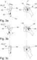
1 : eine perspektivische Ansicht eines medizinischen Instruments mit einer rein symbolisch dargestellten erfindungsgemäßen Eingabeeinheit, in2a bis2c : eine perspektivische Ansicht auf ein Werkzeug des medizinischen Instruments gemäß der1 sowie schematisiert dargestellte erste Eingabemittel der erfindungsgemäßen Eingabeeinheit, in3a bis3c : eine perspektivische Ansicht auf das bekannte Werkzeug aus der2 sowie schematisiert dargestellte zweite Eingabemittel der erfindungsgemäßen Eingabeeinheit, in4 : eine bevorzugte Ausführungsform der erfindungsgemäßen Fußbedieneinheit.
1 : a perspective view of a medical instrument with an input unit according to the invention shown purely symbolically, in2a until2c : a perspective view of a tool of the medical instrument according to FIG1 as well as schematically illustrated first input means of the input unit according to the invention, in3a until3c : a perspective view of the well-known tool from the2 and schematically illustrated second input means of the input unit according to the invention, in4 : a preferred embodiment of the foot control unit according to the invention.
Gleiche Elemente beziehungsweise Elemente mit gleicher Funktion sind in den Figuren mit den gleichen Bezugsziffern versehen.Identical elements or elements with the same function are provided with the same reference numbers in the figures.
In der
Die Steuereinheit 18 ermöglicht einen endlosen rotatorischen Antrieb des figürlich dargestellten um 90° verschwenkten Werkzeugs 16. Dazu kann beispielsweise eine Steuereinheit 18 verwendet werden, wie sie aus der bereits erwähnten
Bei dem Werkzeug 16 handelt es sich um ein mit Maulelementen 34 versehenes Werkzeug 16, insbesondere ein Maulteil 17, wobei die Maulelemente 34 auch über die Steuereinheit 18 zangenartig zwischen einem geöffneten Zustand und einem geschlossenen Zustand verstellbar sind.The
Das Werkzeug 16 ist über einen Gelenkmechanismus 36 relativ zur Längsachse L des Schafts 14 verschwenkbar, wobei der Gelenkmechanismus 36 durch am distalen Ende 32 des Schafts 14 angeordnete Schwenkglieder 38 ausgebildet ist, die über in Längsrichtung L des Schafts 14 verlaufende Lenkdrähte 20 so mit einem nicht figürlich dargestellten, am proximalen Ende 30 des Schafts 14 angeordneten Antrieb 40 verbunden sind, dass eine Bewegung des proximalseitigen Antriebs 40 und eine entsprechende relative Bewegungen der distalseitigen Schwenkglieder 38 ein Verschwenken des Werkzeugs 16 verursacht.The
Ein entsprechender Antrieb 40 ist beispielsweise aus der bereits genannten
Durch die Rotation des Schaftes 14 zusammen mit den Lenkdrähten 20 um die Längsachse L lässt sich das Werkzeug 16 auch relativ zu der Steuereinheit 18 dauerhaft bzw. endlos rotieren. Durch die Verwendung der schwenkbaren und rotierbar gelagerten Scheibe kann das Werkzeug 16 gleichzeitig zu einer dauerhaften Rotation um die Längsachse L auch durch die Lenkdrähte 20 entlang der Längsachse L verstellt werden. Dadurch kann die räumliche Ausrichtung des Werkzeugs 16 bei der dauerhaften Rotation des Schafts 14 ausgeglichen werden, wobei das Werkzeug 16 um seine Erstreckungsachse E mit einer Rotationsbewegung ωE rotiert. Befindet sich das Werkzeug 16 in einem nicht geschwenkten Zustand, so entspricht die Erstreckungsachse E des Werkzeugs 16 der Längsachse L des Schafts 14, erstreckt sich also in z-Richtung des kartesischen Koordinatensystems.Due to the rotation of the
Da die Lenkdrähte 20 zusammen mit dem Schaft 14 um die Längsachse L rotieren können, ist eine endlose Rotation um die Längsachse L oder die Erstreckungsachse E mittels des Antriebs 40 realisierbar, ohne dass sich die Lenkdrähte 20 ineinander zu einer Kordel verdrehen und eine Steuerung der Schwenkbewegung ωx, ωy begrenzen oder verhindern.Since the
In den
In der
Die ersten Eingabemittel 22 sind vorliegend als greifbarer Zylinder ausgebildet, der mittels einer nicht dargestellten kardanischen Aufhängung mit der nicht dargestellten Steuereinheit 18 in Wirkkontakt steht.In the present case, the first input means 22 are designed as a tangible cylinder which is in operative contact with the control unit 18 (not shown) by means of a cardanic suspension (not shown).
Zur Vereinfachung wird davon ausgegangen, dass die ergonomische Benutzereingabe sich lediglich auf eine Rotation des Maulteils 17 um ihre Erstreckungsachse E im ersten Handhabungsmodus beschränkt.For simplification, it is assumed that the ergonomic user input is limited to a rotation of the jaw part 17 about its axis of extension E in the first handling mode.
Die Rotationsbewegung ωz' der ersten Eingabemittel 22 und die Rotationsbewegung ωE des Werkzeugs 16 sind in dem ersten Handhabungsmodus zueinander rotationsgetreu ausgebildet, weisen also betragsweise gleiche Winkelgeschwindigkeiten auf.The rotational movement ωz ′ of the first input means 22 and the rotational movement ωE of the
In der
Die Hand der Bedienperson bleibt bei der ergonomischen Benutzereingabe stets in Kontakt mit den ersten Eingabemitteln 22, es soll also im ersten Handhabungsmodus nicht zu einem Umgreifen oder kurzzeitigen Unterbrechen kommen, da eine kontinuierliche und vorzugsweise ununterbrochene Abbildung der in die ersten Eingabemittel 22 eingebrachten Rotationsbewegung ωz' in die Rotationsbewegung ωE des Maulteils 17 realisiert werden soll. Eine Bedienperson hat also eine kontinuierliche und ununterbrochene Kontrolle über die Verstellbewegung des Werkzeugs 16, insbesondere um präzise komplexe minimalinvasive Eingriffe und/oder medizinische Operationen in einem sensiblen Umfeld durchführen zu können.During ergonomic user input, the operator's hand always remains in contact with the first input means 22, so there should be no gripping around or brief interruptions in the first handling mode, since continuous and preferably uninterrupted mapping of the rotational movement ω introduced into the first input means 22,e.g ' To be realized in the rotational movement ωE of the jaw part 17. An operator therefore has continuous and uninterrupted control over the adjustment movement of the
Durch die Physiologie der menschlichen Hand ist der Rotationsbereich auf einen maximalen Rotationswinkel von etwa ±90° um die Ruhestellung und somit insgesamt auf etwa 180° um die Ruhestellung oder Grundposition beschränkt.Due to the physiology of the human hand, the range of rotation is limited to a maximum angle of rotation of approximately ±90° around the resting position and thus a total of approximately 180° around the resting or basic position.
In der
Die zweiten Eingabemittel 24 sind vorliegend durch den identischen greifbaren Zylinder ausgebildet, um die Steuerung des Werkzeugs 16 sowohl im ersten Handhabungsmodus als auch im zweiten Handhabungsmodus zu realisieren.In the present case, the second input means 24 are formed by the identical tangible cylinder in order to realize the control of the
In der
In der
Durch Zurückführen der zweiten Eingabemittel 24 in die Grundposition gemäß der
In der
Das Rotierelement 402 ist in der abgebildeten Darstellung als zylinderförmiges Rollelement 403 ausgebildet, das eine Längserstreckung von etwa 15cm aufweist. Die Mantelfläche des zylinderförmigen Rollelements 403 ist mit einer äußeren Schicht 420 aus einem Elastomermaterial überzogen, die eine geriffelte oder aufgeraute Oberfläche 424 aufweist.In the illustration shown, the rotating element 402 is in the form of a cylindrical rolling element 403 which has a longitudinal extent of approximately 15 cm. The lateral surface of the cylindrical rolling element 403 is covered with an
Die Fußbedieneinheit 400 umfasst eine keilförmige Gehäuseeinheit 414, die eine abgeschrägte Oberseite 416 aufweist, wobei die abgeschrägte Oberseite 416 eine Öffnung umschließt, aus der das zylinderförmige Rollelement 403 in Radialrichtung RadR bereichsweise übersteht.The foot control unit 400 comprises a wedge-shaped
Vorteilhaft wird die Fußbedieneinheit 400 in einem Betriebszustand 418 der Fußbedieneinheit 400 auf einem Untergrund abgestellt, wobei das zylinderförmige Rollelement 403 so ausgerichtet wird, dass es mit dem um die abgestellte Fußverse schwenkenden Fußballen einer Bedienperson bedienbar ist, um die Rotationsbewegungen in das Rollelement 403 einzubringen.The foot control unit 400 is advantageously placed on a surface in an
Ferner umfasst die abgeschrägte Oberseite 416 eine aus Richtungspfeilen und Buchstaben ausgebildete Kennzeichnung 422, die die Rotationsrichtung des Rollelements 403 für die Auswahl der Rotationsrichtung des Werkzeugs 16 symbolisiert darstellt.Furthermore, the
Beim Bedienen der Fußbedieneinheit 400 muss das Rollelements 403 entsprechend der Kennzeichnung 422 zum Steuern einer linken Rotationsbewegung des Werkzeugs 16 nach links rotiert werden und zum Steuern einer nach rechts gerichteten Rotationsbewegung des Werkzeugs 16 nach rechts rotiert werden. Zur Steuerung von mehreren Vollumdrehungen ist hier ein mehrfaches Überstreichen des rollenartigen Rollelements 403 erforderlich.When operating the foot control unit 400, the rolling element 403 must be rotated according to the marking 422 to the left to control a left rotary movement of the
Alternativ hierzu kann auch eine technische Umsetzung realisiert sein, bei der das Rollelement 403 aus einer figürlich dargestellten Ruhestellung 404 in eine rechte oder erste Stellposition 406 rotierbar ist, wobei in dieser Stellposition 406 eine dauerhafte Rotationsbewegung des Werkzeugs 16 in die rechte Richtung aktivierbar ist. Hierfür ist ein rein schematisierter erster Druckschalter 410 vorgesehen, der in der rechten Stellposition 406 von dem Rollelement 403 aktivierbar ist. Zum Beenden der Rotationsbewegung des Werkzeugs 16 muss das Rollelement 403 wieder in die figürlich dargestellte Ruhestellung 404 zurückverstellt werden. Entsprechend lässt sich das Rollelement 403 auch aus der Ruhestellung 404 in eine linke oder zweite Stellposition 408 rotieren, um einen weiteren, nicht im Detail dargestellten Druckschalter 412 zu betätigen, um eine entsprechende Rotationsrichtung in die linke Richtung zu aktivieren. Somit lässt sich intuitiv die Steuerung des zweiten Handhabungsmodus umsetzten, wobei sich die vorgeschlagene Fußbedieneinheit 400 auch optimal nachrüsten lässt, um gattungsbildende Eingabeeinheiten 10 für die Steuerung des Werkzeugs 16 im ersten Handhabungsmodus auf die zusätzliche Steuerung des Werkzeugs 16 im zweiten Handhabungsmodus nachzurüsten.As an alternative to this, a technical implementation can also be realized in which the rolling element 403 can be rotated from a
BezugszeichenlisteReference List
- 1010
- Eingabeeinheitinput unit
- 1212
- medizinisches Instrumentmedical instrument
- 1414
- Schaftshaft
- 1616
- WerkzeugTool
- 1717
- Maulteiljaw part
- 1818
- Steuereinheitcontrol unit
- 2020
- Lenkdrähtesteering wires
- 2222
- erste Eingabemittelfirst input means
- 2424
- zweite Eingabemittelsecond input means
- 3030
- proximales Ende des Schaftsproximal end of the shaft
- 3232
- distales Ende des Schaftsdistal end of the shaft
- 3434
- Maulelementjaw element
- 3636
- Gelenkmechanismusjoint mechanism
- 3838
- Schwenkgliedswivel link
- 4040
- Antriebdrive
- 4242
- Markierungmark
- 4444
- Endanschlagend stop
- 400400
- Fußbedieneinheitfoot control unit
- 402402
- Rotierelementrotating element
- 403403
- zylinderförmiges Rollelementcylindrical rolling element
- 404404
- Ruhestellung des RotierelementsRest position of the rotating element
- 406406
- rechte Stellpositionright position
- 408408
- linke Stellpositionleft setting position
- 410410
- erster Druckschalterfirst pressure switch
- 412412
- weiterer Druckschalteranother pressure switch
- 414414
- keilförmige Gehäuseeinheitwedge-shaped housing unit
- 416416
- abgeschrägte Oberseitebeveled top
- 418418
- Betriebszustandoperating condition
- 420420
- äußere Schichtouter layer
- 422422
- KennzeichnungLabelling
- 424424
- geriffelte Oberflächecorrugated surface
- 10001000
- medizinisches Systemmedical system
- R1R1
- Rotationsachse des Rotierelements;axis of rotation of the rotating element;
- RadRRadR
- Radialrichtungradial direction
- EE
- Erstreckungsachse des WerkzeugsTool extension axis
- LL
- Längsachse des Schaftslong axis of the shaft
- RR
- Rotationsachseaxis of rotation
- x, y, zx, y, z
- Raumachsen des medizinischen InstrumentsSpatial axes of the medical instrument
- ωEωE
- Rotationsbewegung des Werkzeugsrotation of the tool
- ωz'ωz'
- Rotationbewegung der EingabeeinheitRotational movement of the input unit
- ωx,ωx,
- Schwenkbewegung des WerkzeugsPivoting movement of the tool
- ωyωy
- Schwenkbewegung des WerkzeugsPivoting movement of the tool
Claims (11)
Translated fromGermanPriority Applications (3)
| Application Number | Priority Date | Filing Date | Title |
|---|---|---|---|
| DE102021119629.9ADE102021119629B3 (en) | 2021-07-28 | 2021-07-28 | Input unit for a medical instrument and medical system with an input unit |
| PCT/EP2022/070829WO2023006682A1 (en) | 2021-07-28 | 2022-07-25 | Input unit for a medical instrument, and medical system comprising an input unit |
| EP22758153.5AEP4376751A1 (en) | 2021-07-28 | 2022-07-25 | Input unit for a medical instrument, and medical system comprising an input unit |
Applications Claiming Priority (1)
| Application Number | Priority Date | Filing Date | Title |
|---|---|---|---|
| DE102021119629.9ADE102021119629B3 (en) | 2021-07-28 | 2021-07-28 | Input unit for a medical instrument and medical system with an input unit |
Publications (1)
| Publication Number | Publication Date |
|---|---|
| DE102021119629B3true DE102021119629B3 (en) | 2023-02-02 |
Family
ID=83049790
Family Applications (1)
| Application Number | Title | Priority Date | Filing Date |
|---|---|---|---|
| DE102021119629.9AActiveDE102021119629B3 (en) | 2021-07-28 | 2021-07-28 | Input unit for a medical instrument and medical system with an input unit |
Country Status (3)
| Country | Link |
|---|---|
| EP (1) | EP4376751A1 (en) |
| DE (1) | DE102021119629B3 (en) |
| WO (1) | WO2023006682A1 (en) |
Families Citing this family (1)
| Publication number | Priority date | Publication date | Assignee | Title |
|---|---|---|---|---|
| DE102021119613A1 (en)* | 2021-07-28 | 2023-02-02 | Karl Storz Se & Co. Kg | Input unit for a medical instrument and medical system with an input unit |
Citations (5)
| Publication number | Priority date | Publication date | Assignee | Title |
|---|---|---|---|---|
| US5454827A (en) | 1994-05-24 | 1995-10-03 | Aust; Gilbert M. | Surgical instrument |
| DE102004010205B3 (en) | 2004-03-02 | 2005-10-20 | Siemens Ag | Operating element, in particular for controlling a medical system |
| DE102013004692A1 (en) | 2013-03-19 | 2014-09-25 | Spacecontrol Gmbh | 3D input device with an additional rotary control |
| US20190142530A1 (en) | 2017-11-15 | 2019-05-16 | Intuitive Surgical Operations, Inc. | Foot controller |
| DE102019121092A1 (en) | 2019-08-05 | 2021-02-11 | Karl Storz Se & Co. Kg | MEDICAL INSTRUMENT |
Family Cites Families (4)
| Publication number | Priority date | Publication date | Assignee | Title |
|---|---|---|---|---|
| JP5258284B2 (en)* | 2007-12-28 | 2013-08-07 | テルモ株式会社 | Medical manipulator and medical robot system |
| US8423182B2 (en)* | 2009-03-09 | 2013-04-16 | Intuitive Surgical Operations, Inc. | Adaptable integrated energy control system for electrosurgical tools in robotic surgical systems |
| US10368955B2 (en)* | 2017-03-31 | 2019-08-06 | Johnson & Johnson Innovation-Jjdc, Inc. | Multi-functional foot pedal assembly for controlling a robotic surgical system |
| US10835334B2 (en)* | 2018-02-05 | 2020-11-17 | Meerecompany Inc. | Master console for surgical robot |
- 2021
- 2021-07-28DEDE102021119629.9Apatent/DE102021119629B3/enactiveActive
- 2022
- 2022-07-25WOPCT/EP2022/070829patent/WO2023006682A1/ennot_activeCeased
- 2022-07-25EPEP22758153.5Apatent/EP4376751A1/enactivePending
Patent Citations (5)
| Publication number | Priority date | Publication date | Assignee | Title |
|---|---|---|---|---|
| US5454827A (en) | 1994-05-24 | 1995-10-03 | Aust; Gilbert M. | Surgical instrument |
| DE102004010205B3 (en) | 2004-03-02 | 2005-10-20 | Siemens Ag | Operating element, in particular for controlling a medical system |
| DE102013004692A1 (en) | 2013-03-19 | 2014-09-25 | Spacecontrol Gmbh | 3D input device with an additional rotary control |
| US20190142530A1 (en) | 2017-11-15 | 2019-05-16 | Intuitive Surgical Operations, Inc. | Foot controller |
| DE102019121092A1 (en) | 2019-08-05 | 2021-02-11 | Karl Storz Se & Co. Kg | MEDICAL INSTRUMENT |
Also Published As
| Publication number | Publication date |
|---|---|
| WO2023006682A1 (en) | 2023-02-02 |
| EP4376751A1 (en) | 2024-06-05 |
Similar Documents
| Publication | Publication Date | Title |
|---|---|---|
| EP0781112B1 (en) | Medical manipulator | |
| DE60307257T2 (en) | MANIPULATOR FOR A INSTRUMENT FOR MINIMALLY INVASIVE SURGERY AND INSTRUMENT THEREFOR | |
| EP0901347B2 (en) | Instrument with a bendable handle | |
| DE69735708T2 (en) | DEVICE FOR PERFORMING MINIMALLY INVASIVE PROCEDURES AT THE HEART | |
| DE4340707C2 (en) | manipulator | |
| EP1332484B1 (en) | Simulator device having at least two degrees of freedom of motion for an instrument | |
| EP2869749B1 (en) | Medical instrument for pivoting such a medical instrument | |
| EP1330809B1 (en) | Simulating device with at least two degrees of freedom for an instrument | |
| EP1022989A1 (en) | Instrument or forceps for medical, in particular endoscopic, use | |
| DE102019128277B4 (en) | Passive holding device, modular surgical system and method for handling a trocar | |
| DE102013004692A1 (en) | 3D input device with an additional rotary control | |
| EP3015081B1 (en) | Surgical instrument with a manual control device | |
| DE102021119629B3 (en) | Input unit for a medical instrument and medical system with an input unit | |
| WO2017186414A1 (en) | Surgery-assistance system and method for generating control signals for actuating a surgery assistance system kinematic robot which can be moved in a motor-controlled manner | |
| DE4324254C1 (en) | Surgical instrument for endoscopic surgery | |
| EP3363399A1 (en) | Controller for a robot-assisted surgical system | |
| DE102021119618B4 (en) | Input unit for a medical instrument and medical system with an input unit | |
| DE102021119641B4 (en) | Input unit for a medical instrument and medical system with an input unit | |
| DE102021119646B4 (en) | Input unit for a medical instrument and medical system with an input unit | |
| EP2491874A1 (en) | Surgical instrument with improved handling | |
| DE102021119613A1 (en) | Input unit for a medical instrument and medical system with an input unit | |
| DE102021110086A1 (en) | Manually operable control device and medical instrument with such a control device | |
| DE102017114838A1 (en) | Gear assembly and surgical instrument with a gear assembly | |
| DE102021119624A1 (en) | Input unit for a medical instrument and medical system with an input unit | |
| WO2002043030A2 (en) | Device for simulating a rod-shaped surgical instrument with a back-coupling of forces |
Legal Events
| Date | Code | Title | Description |
|---|---|---|---|
| R012 | Request for examination validly filed | ||
| R079 | Amendment of ipc main class | Free format text:PREVIOUS MAIN CLASS: A61B0017000000 Ipc:G05G0011000000 | |
| R016 | Response to examination communication | ||
| R018 | Grant decision by examination section/examining division | ||
| R020 | Patent grant now final |