DE102021118775A1 - Method for adjusting the lifting position of a machine frame of a floor milling machine and floor milling machine connected via lifting devices to driving devices - Google Patents
Method for adjusting the lifting position of a machine frame of a floor milling machine and floor milling machine connected via lifting devices to driving devicesDownload PDFInfo
- Publication number
- DE102021118775A1 DE102021118775A1DE102021118775.3ADE102021118775ADE102021118775A1DE 102021118775 A1DE102021118775 A1DE 102021118775A1DE 102021118775 ADE102021118775 ADE 102021118775ADE 102021118775 A1DE102021118775 A1DE 102021118775A1
- Authority
- DE
- Germany
- Prior art keywords
- machine frame
- longitudinal inclination
- lifting
- machine
- devices
- Prior art date
- Legal status (The legal status is an assumption and is not a legal conclusion. Google has not performed a legal analysis and makes no representation as to the accuracy of the status listed.)
- Pending
Links
Images


Classifications
- E—FIXED CONSTRUCTIONS
- E01—CONSTRUCTION OF ROADS, RAILWAYS, OR BRIDGES
- E01C—CONSTRUCTION OF, OR SURFACES FOR, ROADS, SPORTS GROUNDS, OR THE LIKE; MACHINES OR AUXILIARY TOOLS FOR CONSTRUCTION OR REPAIR
- E01C23/00—Auxiliary devices or arrangements for constructing, repairing, reconditioning, or taking-up road or like surfaces
- E01C23/06—Devices or arrangements for working the finished surface; Devices for repairing or reconditioning the surface of damaged paving; Recycling in place or on the road
- E01C23/08—Devices or arrangements for working the finished surface; Devices for repairing or reconditioning the surface of damaged paving; Recycling in place or on the road for roughening or patterning; for removing the surface down to a predetermined depth high spots or material bonded to the surface, e.g. markings; for maintaining earth roads, clay courts or like surfaces by means of surface working tools, e.g. scarifiers, levelling blades
- E01C23/085—Devices or arrangements for working the finished surface; Devices for repairing or reconditioning the surface of damaged paving; Recycling in place or on the road for roughening or patterning; for removing the surface down to a predetermined depth high spots or material bonded to the surface, e.g. markings; for maintaining earth roads, clay courts or like surfaces by means of surface working tools, e.g. scarifiers, levelling blades using power-driven tools, e.g. vibratory tools
- E01C23/088—Rotary tools, e.g. milling drums
- B—PERFORMING OPERATIONS; TRANSPORTING
- B60—VEHICLES IN GENERAL
- B60G—VEHICLE SUSPENSION ARRANGEMENTS
- B60G17/00—Resilient suspensions having means for adjusting the spring or vibration-damper characteristics, for regulating the distance between a supporting surface and a sprung part of vehicle or for locking suspension during use to meet varying vehicular or surface conditions, e.g. due to speed or load
- B60G17/015—Resilient suspensions having means for adjusting the spring or vibration-damper characteristics, for regulating the distance between a supporting surface and a sprung part of vehicle or for locking suspension during use to meet varying vehicular or surface conditions, e.g. due to speed or load the regulating means comprising electric or electronic elements
- B60G17/016—Resilient suspensions having means for adjusting the spring or vibration-damper characteristics, for regulating the distance between a supporting surface and a sprung part of vehicle or for locking suspension during use to meet varying vehicular or surface conditions, e.g. due to speed or load the regulating means comprising electric or electronic elements characterised by their responsiveness, when the vehicle is travelling, to specific motion, a specific condition, or driver input
- B—PERFORMING OPERATIONS; TRANSPORTING
- B60—VEHICLES IN GENERAL
- B60G—VEHICLE SUSPENSION ARRANGEMENTS
- B60G17/00—Resilient suspensions having means for adjusting the spring or vibration-damper characteristics, for regulating the distance between a supporting surface and a sprung part of vehicle or for locking suspension during use to meet varying vehicular or surface conditions, e.g. due to speed or load
- B60G17/005—Suspension locking arrangements
- B—PERFORMING OPERATIONS; TRANSPORTING
- B60—VEHICLES IN GENERAL
- B60G—VEHICLE SUSPENSION ARRANGEMENTS
- B60G17/00—Resilient suspensions having means for adjusting the spring or vibration-damper characteristics, for regulating the distance between a supporting surface and a sprung part of vehicle or for locking suspension during use to meet varying vehicular or surface conditions, e.g. due to speed or load
- B60G17/015—Resilient suspensions having means for adjusting the spring or vibration-damper characteristics, for regulating the distance between a supporting surface and a sprung part of vehicle or for locking suspension during use to meet varying vehicular or surface conditions, e.g. due to speed or load the regulating means comprising electric or electronic elements
- B60G17/0152—Resilient suspensions having means for adjusting the spring or vibration-damper characteristics, for regulating the distance between a supporting surface and a sprung part of vehicle or for locking suspension during use to meet varying vehicular or surface conditions, e.g. due to speed or load the regulating means comprising electric or electronic elements characterised by the action on a particular type of suspension unit
- B—PERFORMING OPERATIONS; TRANSPORTING
- B60—VEHICLES IN GENERAL
- B60G—VEHICLE SUSPENSION ARRANGEMENTS
- B60G17/00—Resilient suspensions having means for adjusting the spring or vibration-damper characteristics, for regulating the distance between a supporting surface and a sprung part of vehicle or for locking suspension during use to meet varying vehicular or surface conditions, e.g. due to speed or load
- B60G17/015—Resilient suspensions having means for adjusting the spring or vibration-damper characteristics, for regulating the distance between a supporting surface and a sprung part of vehicle or for locking suspension during use to meet varying vehicular or surface conditions, e.g. due to speed or load the regulating means comprising electric or electronic elements
- B60G17/019—Resilient suspensions having means for adjusting the spring or vibration-damper characteristics, for regulating the distance between a supporting surface and a sprung part of vehicle or for locking suspension during use to meet varying vehicular or surface conditions, e.g. due to speed or load the regulating means comprising electric or electronic elements characterised by the type of sensor or the arrangement thereof
- B60G17/01908—Acceleration or inclination sensors
- B—PERFORMING OPERATIONS; TRANSPORTING
- B60—VEHICLES IN GENERAL
- B60G—VEHICLE SUSPENSION ARRANGEMENTS
- B60G3/00—Resilient suspensions for a single wheel
- B60G3/01—Resilient suspensions for a single wheel the wheel being mounted for sliding movement, e.g. in or on a vertical guide
- B—PERFORMING OPERATIONS; TRANSPORTING
- B62—LAND VEHICLES FOR TRAVELLING OTHERWISE THAN ON RAILS
- B62D—MOTOR VEHICLES; TRAILERS
- B62D55/00—Endless track vehicles
- B62D55/06—Endless track vehicles with tracks without ground wheels
- B62D55/062—Tracked vehicles of great dimensions adapted for moving bulky loads or gear
- B—PERFORMING OPERATIONS; TRANSPORTING
- B62—LAND VEHICLES FOR TRAVELLING OTHERWISE THAN ON RAILS
- B62D—MOTOR VEHICLES; TRAILERS
- B62D55/00—Endless track vehicles
- B62D55/08—Endless track units; Parts thereof
- B62D55/104—Suspension devices for wheels, rollers, bogies or frames
- B62D55/116—Attitude or position control of chassis by action on suspension, e.g. to compensate for a slope
- E—FIXED CONSTRUCTIONS
- E01—CONSTRUCTION OF ROADS, RAILWAYS, OR BRIDGES
- E01C—CONSTRUCTION OF, OR SURFACES FOR, ROADS, SPORTS GROUNDS, OR THE LIKE; MACHINES OR AUXILIARY TOOLS FOR CONSTRUCTION OR REPAIR
- E01C23/00—Auxiliary devices or arrangements for constructing, repairing, reconditioning, or taking-up road or like surfaces
- E01C23/06—Devices or arrangements for working the finished surface; Devices for repairing or reconditioning the surface of damaged paving; Recycling in place or on the road
- E01C23/12—Devices or arrangements for working the finished surface; Devices for repairing or reconditioning the surface of damaged paving; Recycling in place or on the road for taking-up, tearing-up, or full-depth breaking-up paving, e.g. sett extractor
- E01C23/122—Devices or arrangements for working the finished surface; Devices for repairing or reconditioning the surface of damaged paving; Recycling in place or on the road for taking-up, tearing-up, or full-depth breaking-up paving, e.g. sett extractor with power-driven tools, e.g. oscillated hammer apparatus
- E01C23/127—Devices or arrangements for working the finished surface; Devices for repairing or reconditioning the surface of damaged paving; Recycling in place or on the road for taking-up, tearing-up, or full-depth breaking-up paving, e.g. sett extractor with power-driven tools, e.g. oscillated hammer apparatus rotary, e.g. rotary hammers
- B—PERFORMING OPERATIONS; TRANSPORTING
- B60—VEHICLES IN GENERAL
- B60G—VEHICLE SUSPENSION ARRANGEMENTS
- B60G2202/00—Indexing codes relating to the type of spring, damper or actuator
- B60G2202/40—Type of actuator
- B60G2202/41—Fluid actuator
- B60G2202/413—Hydraulic actuator
- B—PERFORMING OPERATIONS; TRANSPORTING
- B60—VEHICLES IN GENERAL
- B60G—VEHICLE SUSPENSION ARRANGEMENTS
- B60G2300/00—Indexing codes relating to the type of vehicle
- B60G2300/09—Construction vehicles, e.g. graders, excavators
- B—PERFORMING OPERATIONS; TRANSPORTING
- B60—VEHICLES IN GENERAL
- B60G—VEHICLE SUSPENSION ARRANGEMENTS
- B60G2300/00—Indexing codes relating to the type of vehicle
- B60G2300/32—Track vehicles
- B—PERFORMING OPERATIONS; TRANSPORTING
- B60—VEHICLES IN GENERAL
- B60G—VEHICLE SUSPENSION ARRANGEMENTS
- B60G2400/00—Indexing codes relating to detected, measured or calculated conditions or factors
- B60G2400/60—Load
- B60G2400/63—Location of the center of gravity
- B—PERFORMING OPERATIONS; TRANSPORTING
- B60—VEHICLES IN GENERAL
- B60G—VEHICLE SUSPENSION ARRANGEMENTS
- B60G2401/00—Indexing codes relating to the type of sensors based on the principle of their operation
- B60G2401/14—Photo or light sensitive means, e.g. Infrared
- B—PERFORMING OPERATIONS; TRANSPORTING
- B60—VEHICLES IN GENERAL
- B60G—VEHICLE SUSPENSION ARRANGEMENTS
- B60G2401/00—Indexing codes relating to the type of sensors based on the principle of their operation
- B60G2401/17—Magnetic/Electromagnetic
- B—PERFORMING OPERATIONS; TRANSPORTING
- B60—VEHICLES IN GENERAL
- B60G—VEHICLE SUSPENSION ARRANGEMENTS
- B60G2401/00—Indexing codes relating to the type of sensors based on the principle of their operation
- B60G2401/28—Gyroscopes
- B—PERFORMING OPERATIONS; TRANSPORTING
- B60—VEHICLES IN GENERAL
- B60G—VEHICLE SUSPENSION ARRANGEMENTS
- B60G2500/00—Indexing codes relating to the regulated action or device
- B60G2500/30—Height or ground clearance
- B—PERFORMING OPERATIONS; TRANSPORTING
- B60—VEHICLES IN GENERAL
- B60G—VEHICLE SUSPENSION ARRANGEMENTS
- B60G2800/00—Indexing codes relating to the type of movement or to the condition of the vehicle and to the end result to be achieved by the control action
- B60G2800/01—Attitude or posture control
- B60G2800/019—Inclination due to load distribution or road gradient
- B60G2800/0192—Inclination due to load distribution or road gradient longitudinal with regard to vehicle
- E—FIXED CONSTRUCTIONS
- E01—CONSTRUCTION OF ROADS, RAILWAYS, OR BRIDGES
- E01C—CONSTRUCTION OF, OR SURFACES FOR, ROADS, SPORTS GROUNDS, OR THE LIKE; MACHINES OR AUXILIARY TOOLS FOR CONSTRUCTION OR REPAIR
- E01C2301/00—Machine characteristics, parts or accessories not otherwise provided for
Landscapes
- Engineering & Computer Science (AREA)
- Mechanical Engineering (AREA)
- Mining & Mineral Resources (AREA)
- Architecture (AREA)
- Civil Engineering (AREA)
- Structural Engineering (AREA)
- Chemical & Material Sciences (AREA)
- Combustion & Propulsion (AREA)
- Transportation (AREA)
- Road Repair (AREA)
- Road Paving Machines (AREA)
- Lifting Devices For Agricultural Implements (AREA)
Abstract
Translated fromGermanDescription
Translated fromGermanDie Erfindung betrifft ein Verfahren zum Einstellen der Hublage eines über Hubeinrichtungen mit Fahreinrichtungen verbundenen Maschinenrahmens einer Bodenfräsmaschine sowie eine Bodenfräsmaschine, insbesondere zum Durchfuhren des erfindungsgemäßen Verfahrens.The invention relates to a method for adjusting the stroke position of a machine frame of a floor milling machine that is connected to travel devices via lifting devices, and to a floor milling machine, in particular for carrying out the method according to the invention.
Gattungsgemäße Bodenfräsmaschinen sind beispielsweise aus der
Um verschiedene Höhenpositionierungen des Maschinenrahmens gegenüber dem Bodenuntergrund zu ermöglichen, ist wenigstens ein Paar der vorderen und/oder hinteren Fahreinrichtungen über in Vertikalrichtung verstellbare Hubeinrichtungen, umfassend üblicherweise einen Aktor, wie beispielsweise eine hydraulisch angetriebene Zylinder-Kolben-Einheit, mit dem Maschinenrahmen verbunden. Die Hubeinrichtungen sind funktional in der Weise ausgebildet, dass sie den Abstand zwischen dem Maschinenrahmen und der Fahreinrichtung, insbesondere zumindest anteilig in Vertikalrichtung, variieren können, um eine Hubverstellung in Vertikalrichtung des Maschinenrahmens gegenüber dem Bodenuntergrund zu bewirken. Eine solche Hubverstellung kann beispielsweise zu Beginn eines Fräsprozesses durch Absenken der Bodenfräsmaschine bis hin zu einer gewünschten Frästiefe und/oder zur Ausrichtung des Maschinenrahmens, beispielsweise beim Überfahren von Hindernissen, und/oder zum Anheben der Fräseinrichtung über den Bodenuntergrund bei Transportfahrt genutzt werden. Diese Hubeinrichtungen können als sogenannten Hubsäulen linear verstellbar ausgebildet sein. Femer umfassen gattungsgemäße Bodenfräsmaschinen eine Steuereinrichtung, die zur Steuerung der Hubverstellung der Hubeinrichtungen durch die jeweiligen Aktoren ausgebildet ist. Eine Hauptaufgabe der Steuereinrichtung kann darin liegen, eine zueinander koordinierte Verstellung der Stellglieder bzw. Hubeinrichtungen zu ermöglichen, um einerseits die Höhenverstellung der Baumaschine an sich und andererseits die Lage des Maschinenrahmens üblicherweise gegenüber dem Bodenuntergrund regulieren zu können.In order to enable the machine frame to be positioned at different heights relative to the ground, at least one pair of the front and/or rear driving devices is connected to the machine frame via lifting devices that can be adjusted in the vertical direction, usually comprising an actuator, such as a hydraulically driven cylinder-piston unit. The lifting devices are functionally designed in such a way that they can vary the distance between the machine frame and the driving device, in particular at least partially in the vertical direction, in order to effect a stroke adjustment in the vertical direction of the machine frame relative to the ground. Such a stroke adjustment can be used, for example, at the beginning of a milling process by lowering the floor milling machine to a desired milling depth and/or to align the machine frame, for example when driving over obstacles, and/or to raise the milling device above the ground during transport. These lifting devices can be designed as so-called lifting columns that are linearly adjustable. Furthermore, floor milling machines of this type include a control device which is designed to control the stroke adjustment of the lifting devices by the respective actuators. A main task of the control device can be to enable a mutually coordinated adjustment of the actuators or lifting devices in order to be able to regulate the height adjustment of the construction machine itself and the position of the machine frame usually relative to the ground.
Insbesondere dann, wenn sämtliche der vorhandenen Fahreinrichtungen höhenverstellbar gegenüber dem Maschinenrahmen sind, stellt die Steuerung der einzelnen Hubeinrichtungen eine beträchtliche Herausforderung an den Bediener dar, der gleichzeitig die übrigen Funktionen der Bodenfräsmaschine, wie beispielsweise den Fräsprozess an sich und den Verladevorgang des Fräsgutes sowie das Umfeld der Maschine, beobachten muss.In particular, when all of the existing driving devices are height-adjustable relative to the machine frame, controlling the individual lifting devices poses a considerable challenge to the operator, who at the same time controls the other functions of the floor milling machine, such as the milling process itself and the loading process of the milled material as well as the environment the machine, must observe.
Hiervon ausgehend ist es die Aufgabe der Erfindung, eine Möglichkeit anzugeben, den Bediener einer Bodenfräsmaschine zu entlasten und den Bedienkomfort der Bodenfräsmaschine zu erhöhen.Proceeding from this, it is the object of the invention to provide a way of relieving the operator of a ground milling machine and increasing the ease of use of the ground milling machine.
Die Lösung der Aufgabe gelingt mit einer Baumaschine sowie einem Verfahren gemäß den unabhängigen Ansprüchen. Bevorzugte Weiterbildungen sind in den abhängigen Ansprüchen angegeben.The task is solved with a construction machine and a method according to the independent claims. Preferred developments are specified in the dependent claims.
Ein erster Aspekt der Erfindung betrifft ein Verfahren zum Einstellen der Hublage eines über Hubeinrichtungen mit Fahreinrichtungen verbundenen Maschinenrahmens einer Bodenfräsmaschine. Das erfindungsgemäße Verfahren sieht ein Erfassen und Überwachen einer Ist-Längsneigung des Maschinenrahmens gegenüber einer Lotrichtung mit wenigstens einem Längsneigungssensor und Übermitteln der Ist-Längsneigung des Maschinenrahmens an eine Steuereinheit. Wesentlich ist somit, dass der direkte oder indirekte Bezug der Ermittlung der Längsneigung auf die Lotrichtung, d.h. insbesondere die örtliche Richtung der Schwerebeschleunigung, bezogen ist und somit nicht auf eine lokale durch den jeweiligen Bodenuntergrund bestimmte Referenzfläche. Erfindungsgemäß erfolgt die Ermittlung der Längsneigung der Bodenfräsmaschine somit unabhängig von den örtlichen Gegebenheiten, in denen sich die Bodenfräsmaschine gerade befindet, und insbesondere auch nicht durch eine Erfassung der Lage einer Bodenebene, auf der die Bodenfräsmaschine aktuell aufsteht. Die Längsneigung bezeichnet dabei die Neigung des Maschinenrahmens gegenüber dieser Lotrichtung in einer virtuellen Referenzebene, die durch die Lotrichtung und die Längserstreckung bzw. die Vorwärtsfahrrichtung der Bodenfräsmaschine definiert ist.A first aspect of the invention relates to a method for adjusting the lifting position of a machine frame of a ground milling machine that is connected to driving devices via lifting devices. The method according to the invention involves detecting and monitoring an actual longitudinal inclination of the machine frame in relation to a vertical direction with at least one longitudinal inclination sensor and transmitting the actual longitudinal inclination of the machine frame to a control unit. It is therefore essential that the direct or indirect reference of the determination of the longitudinal inclination is related to the vertical direction, ie in particular the local direction of the gravitational acceleration, and thus not to a local reference area determined by the respective subsoil. According to the invention, the longitudinal inclination of the ground milling machine is determined independently of the local conditions in which the ground milling machine is currently located, and in particular not by detecting the position of a ground level on which the ground milling machine is currently standing. The longitudinal inclination refers to the inclination of the machine frame in relation to this vertical direction in a virtual reference plane that runs through the vertical direction and the longitudinal extent or the forward direction of travel of the ground milling machine is defined.
Ferner ist erfindungsgemäß das Definieren einer Soll-Längsneigung des Maschinenrahmens vorgesehen. Dies kann manuell erfolgen oder auch durch eine Steuereinheit unterstützt, beispielsweise derart, dass bei Inbetriebnahme der Bodenfräsmaschine und/oder in bestimmten Betriebssituationen eine oder mehrere vordefinierte Längsneigungslagen des Maschinenrahmens von der Steuereinheit gesteuert angefahren werden. Insbesondere kann es vorgesehen sein, dass der Bediener der Bodenfräsmaschine eine gewünschte Lage des Maschinenrahmens, zumindest in Bezug auf dessen Längsneigung, einstellt und anschließend diese Längsneigungslage per manuellen Steuerbefehl, beispielsweise per Betätigung eines Bedienelementes, individuell als Soll-Längsneigung definiert.Furthermore, according to the invention, the definition of a desired longitudinal inclination of the machine frame is provided. This can be done manually or supported by a control unit, for example in such a way that when the ground milling machine is started up and/or in certain operating situations, one or more predefined longitudinal inclination positions of the machine frame are approached in a controlled manner by the control unit. In particular, it can be provided that the operator of the ground milling machine sets a desired position of the machine frame, at least in relation to its longitudinal inclination, and then individually defines this longitudinal inclination position as the desired longitudinal inclination using a manual control command, for example by actuating a control element.
Dann, wenn die Ist-Längsneigung von der Soll-Längsneigung abweicht, ist erfindungsgemäß ein geregeltes Nachfuhren der Hublage hinterer oder vorderer Hubeinrichtungen durch eine Steuereinheit vorgesehen. Dies kann insbesondere im laufenden Fahrbetrieb der Bodenfräsmaschine erfolgen. Die Regelung erfolgt derart, dass die Ist-Längsneigung der Soll-Längsneigung des Maschinenrahmens angenähert wird, idealerweise bis die Ist-Längsneigung der Soll-Längsneigung entspricht. Dies setzt einen entsprechenden Regelkreis voraus, dessen Regelgröße die mithilfe der Längsneigungssensors ermittelte Ist-Längsneigung und dessen Steuergröße eine Huberstellung der Hubeinrichtungen vorderer und/oder hintere Fahreinrichtungen und dessen Stellglied beispielsweise ein Schaltventil einer Hydraulikversorgung der Hubeinrichtung etc. sein kann. Bevorzugt erfolgt das geregelte Nachführen automatisch und selbsttätig von der Steuereinheit gesteuert. Es kann auch ein semiautomatischer Betriebsmodus vorgesehen sein, bei dem die Steuereinheit dem Fahrer zunächst signalisiert, dass eine „Nachregelung“ erforderlich wäre, wenn die Soll-Längsneigung aufrecht erhalten werden soll, diese aber erst dann durchgeführt wird, wenn der Bediener, insbesondere per manuellem Steuerbefehl, die Nachregelung startet.If the actual longitudinal inclination deviates from the desired longitudinal inclination, a controlled tracking of the stroke position of rear or front lifting devices is provided by a control unit according to the invention. This can be done in particular while the ground milling machine is being driven. The regulation takes place in such a way that the actual longitudinal inclination is approximated to the desired longitudinal inclination of the machine frame, ideally until the actual longitudinal inclination corresponds to the desired longitudinal inclination. This requires a corresponding control circuit, the controlled variable of which is the actual longitudinal inclination determined using the longitudinal inclination sensor and the control variable of which can be a lifting position of the lifting devices of the front and/or rear driving devices and whose actuator can be, for example, a switching valve of a hydraulic supply to the lifting device etc. The regulated tracking preferably takes place automatically and automatically, controlled by the control unit. A semi-automatic operating mode can also be provided, in which the control unit first signals to the driver that a "readjustment" would be necessary if the target longitudinal inclination is to be maintained, but this is only carried out when the operator, in particular by manual Control command that starts readjustment.
Der Schritt c) kann vorzugsweise grenzwertabhängig erfolgen. Dies bedeutet, dass nicht jede kleinste Abweichung zwischen dem Ist-Längsneigungswert und dem Soll-Längsneigungswert eine Anpassung der Hubverstellung bzw. eine Durchführung einer Hubverstellung initiiert. Vorzugsweise kann ein geregeltes Nachführen erst beim Überschreiten eines Differenzgrenzwertes zwischen der Soll-Längsneigung und der Ist-Längsneigung gestartet werden. Der Differenzgrenzwert kann manuell vorgegeben oder in der Steuereinheit, beispielsweise ab Werk, fix vorgegeben sein. Ergänzend oder alternativ kann das geregelte Nachführen zeitabhängig erst nach Ablauf eines festgelegten Zeitintervalls erfolgen. Auch die Länge des Zeitintervalls kann manuell vorgegeben oder in der Steuereinheit, beispielsweise ab Werk, fix definiert sein.Step c) can preferably take place as a function of the limit value. This means that not every smallest deviation between the actual longitudinal gradient value and the desired longitudinal gradient value initiates an adjustment of the lift adjustment or a lift adjustment. Regulated tracking can preferably only be started when a difference limit value between the setpoint longitudinal inclination and the actual longitudinal inclination is exceeded. The difference limit value can be specified manually or fixed in the control unit, for example at the factory. In addition or as an alternative, the controlled tracking can take place as a function of time only after a specified time interval has elapsed. The length of the time interval can also be specified manually or permanently defined in the control unit, for example at the factory.
Eine weitere Weiterbildung des erfindungsgemäßen Verfahrens sieht vor, dass das Zeitintervall von der Steuereinheit dynamisch angepasst wird, derart, dass die Länge des Zeitintervalls bei steigenden Differenzgrenzwerten sinkt und umgekehrt. Je eklatanter die Abweichung zwischen der Ist-Längsneigung und der Soll-Längsneigung somit ist, desto kürzer soll das Zeitintervall sein. Hier können für die Zeit und/oder die Differenz zwischen Ist- und Soll-Längsneigung zur dynamischen Anpassung zudem weitere Grenzwerte definiert werden, bei deren Über- und/oder Unterschreiten beispielsweise gar kein Zeitglied und/oder gar kein Differenzglied mehr zwischen Ist-Längsneigung und Soll-Längsneigung mehr vorgesehen ist.A further development of the method according to the invention provides that the time interval is dynamically adjusted by the control unit in such a way that the length of the time interval decreases as the difference limit values increase, and vice versa. The more striking the deviation between the actual longitudinal gradient and the target longitudinal gradient is, the shorter the time interval should be. Additional limit values can also be defined here for the time and/or the difference between the actual and target longitudinal inclination for dynamic adjustment, if they are exceeded and/or fallen below, for example, there is no time element and/or no difference element at all between the actual longitudinal inclination and the Desired longitudinal inclination more is provided.
Es kann ergänzend oder alternativ vorgesehen sein, dass die aktuell ermittelte Längsneigung des Maschinenrahmens dem Fahrer angezeigt wird und/oder von der Steuereinheit genutzt wird, um festzustellen, ob die Maschine gerade auf einem horizontal verlaufendem Untergrund, bergauf oder bergab fahrt. Letzteres kann beispielsweise auch in Kombination mit einem Abgleich der Längsneigung des Maschinenrahmens zum Verlauf des Bodenuntergrundes in Vorwärtsrichtung der Maschine erfolgen. Es kann auch vorgesehen sein, dass eine Änderung der aktuell ermittelten Längsneigung des Maschinenrahmens und/oder eine aktuelle Differenz zu einer festgelegten Längsneigung angezeigt und/oder von der Steuereinheit zur Einstellung einer oder mehrerer Hublagen der Hubeinrichtungen genutzt wird. Dies kann beispielsweise dazu genutzt werden, um das Einfahren in eine Steigung oder in ein Gefälle und/oder das Überfahren einer Fräskante zu detektieren.In addition or as an alternative, it can be provided that the currently determined longitudinal inclination of the machine frame is displayed to the driver and/or used by the control unit to determine whether the machine is traveling on horizontal ground, uphill or downhill. The latter can also be done, for example, in combination with a comparison of the longitudinal inclination of the machine frame with the course of the ground in the forward direction of the machine. It can also be provided that a change in the currently determined longitudinal inclination of the machine frame and/or a current difference from a specified longitudinal inclination is displayed and/or used by the control unit to set one or more lifting positions of the lifting devices. This can be used, for example, to detect entering an uphill or downhill gradient and/or driving over a milled edge.
Weiter ergänzend oder alternativ ist es bevorzugt, wenn wenigstens ein Längsneigungsgrenzwert definiert ist, der eine maximale/minimale Längsneigung des Maschinenrahmens in Vorwärtsrichtung definiert und begrenzt. Dies kann beispielsweise dann hilfreich sein, wenn die Maschine in einem Gefälle oder einer Steigung in Vorwärtsrichtung betrieben wird. Je größer der Winkel des Gefälles/der Steigung gegenüber einer virtuellen Horizontalen zur Lotrichtung ist, desto größer müssen die Unterschiede der Stellpositionen der vorderen und/oder hinteren Hubeinrichtungen sein, um die Ist-Längsneigung des Maschinenrahmens aufrecht zu erhalten. Um jedoch auch in Extremlagen der Maschine immer noch eine Stellwegreserve zur Verfügung zu haben, ist es vorteilhaft, wenn die Steuerung das weitere Nachführen der vorderen und/oder hinteren Hubeinrichtungen in Abhängigkeit von der Ist-Längsneigung bei Erreichen bestimmter maximaler/minimaler Längsneigungslagen des Maschinenrahmens unterbindet.In addition or as an alternative, it is preferred if at least one longitudinal inclination limit value is defined, which defines and limits a maximum/minimum longitudinal inclination of the machine frame in the forward direction. This can be useful, for example, when operating the machine in the forward direction on a downhill or uphill slope. The greater the angle of the slope/slope relative to a virtual horizontal to the vertical direction, the greater the differences in the setting positions of the front and/or rear lifting devices must be in order to maintain the actual longitudinal inclination of the machine frame. However, in order to still have a travel reserve available even in extreme positions of the machine, it is advantageous if the controller allows the further tracking of the front and/or rear lifting devices depending on the actual longitudinal inclination when reaching certain maximum/minimum longitudinal inclination positions of the machine frame.
Im Betrieb gattungsgemäßer Bodenfräsmaschinen ist es bekannt, dass sogenannten Nivelliereinrichtungen verwendet werden, über die eine Regelung der aktuellen Frästiefe erfolgt. Dazu kann beispielsweise auf Stellwegsensoren, insbesondere an einem oder mehreren Seitenschilden, und/oder beispielsweise kontaktlosen Abstandssensoren, wie beispielsweise Ultraschall- oder Lasersensoren und/oder eine oder mehrere Kameras zur optischen Abstandsbestimmung, zurückgegriffen werden, mit denen die aktuelle Frästiefe, beispielsweise über eine Ermittlung der Relativhublage des oder der Seitenschilde relativ zum Maschinenrahmen, bestimmbar und überwachbar ist. Es ist nun bevorzugt, dass das erfindungsgemäße Verfahren zur Einstellung der Hublage wenigstens einer Hubeinrichtung in Abhängigkeit von der Längsneigung des Maschinenrahmens in Vorwärtsrichtung derart ausgebildet ist, dass bei einem Steuer- oder Regeleingriff dieses Verfahrens eine solche Nivellierregelung außer Kraft gesetzt wird. Wenn eine geregeltes Nachführen der Hublage hinterer oder vorderer Hubeinrichtungen durch die Steuereinheit zur Anpassung der Ist-Längsneigung an die Soll-Längsneigung erfolgt, werden somit gleichzeitig Regelungseingriffe an eine, mehrere oder alle Hubeinrichtungen durch die Nivelliereinrichtung nicht zugelassen bzw. unterbunden. Diesbezüglich ist diese Regelung somit der Nivellierregelung bevorzugt priorisiert.In the operation of ground milling machines of this type, it is known that so-called leveling devices are used, via which the current milling depth is regulated. For this purpose, travel sensors, in particular on one or more side plates, and/or, for example, contactless distance sensors, such as ultrasonic or laser sensors and/or one or more cameras for optical distance determination, can be used, with which the current milling depth can be determined, for example via a determination the relative stroke position of the side plate or plates relative to the machine frame, can be determined and monitored. It is now preferred that the method according to the invention for setting the lifting position of at least one lifting device as a function of the longitudinal inclination of the machine frame in the forward direction is designed in such a way that such a leveling control is overridden when this method is controlled or regulated. If the stroke position of rear or front lifting devices is adjusted in a controlled manner by the control unit to adapt the actual longitudinal inclination to the desired longitudinal inclination, control interventions in one, several or all lifting devices by the leveling device are not permitted or prevented at the same time. In this regard, this regulation is therefore preferably prioritized over the leveling regulation.
Ergänzend zu den vorstehenden erfindungsgemäßen Verfahrensschritten kann es vorgesehen sein, dass die Gewichtskraftverteilung an den Hubeinrichtungen, insbesondere den Hubsäulen, ermittelt wird, wie beispielsweise in der
Es ist bekannt, dass gattungsgemäße Bodenfräsmaschinen ein sogenanntes Verladeförderband umfassen, mit dessen Hilfe das im Fräsprozess erzeugte Fräsgut auf beispielsweise ein Transportfahrzeug überladen werden kann. Derartige Förderbänder sind unter anderem in den Druckschriften
Es sind Bodenfräsmaschinen bekannt, bei denen beispielsweise nur die vorderen oder nur die hinteren Fahreinrichtungen über Hubeinrichtungen mit dem Maschinenrahmen verbunden sind. Die Erfindung betrifft allerdings ganz besonders solche Bodenfräsmaschinen, bei denen alle vorderen und hinteren Fahreinrichtungen jeweils über eine Hubeinrichtung mit dem Maschinenrahmen verbunden sind. Insbesondere für solche Bodenfräsmaschinen ist es vorteilhaft, wenn das geregelte Nachführen der Hublage durch die Steuereinheit ausschließlich bezüglich Hubeinrichtungen der vorderen oder der hinteren Fahreinrichtungen erfolgt. Dies bedeutet, dass die nachregelnde Einstellung der Ist-Längsneigung im Regelvorgang somit exklusiv nur durch eine Ansteuerung der Hubeinrichtungen der vorderen oder der hinteren Hubeinrichtungen durch die Steuereinheit erfolgt. Insbesondere für Bodenfräsmaschinen mit einem solchen Grundaufbau ist es nun weiter bevorzugt, wenn die von der Steuereinheit im Schritt c) geregelt nachgeführten vorderen oder hinteren Hubeinrichtungen bezüglich ihrer individuellen Hublage pendelnd miteinander gekoppelt sind. Eine pendelnde Koppelung liegt dann vor, wenn eine Ausfahrbewegung der einen Hubeinrichtung eine entgegengerichtete Einfahrbewegung der auf der anderen Seite der Maschine angeordneten Hubeinrichtung zur Folge hat. Eine derartige Pendellagerung ist an sich im Stand der Technik bekannt und kann beispielsweise mittels hydraulischer Zwangskoppelung oder auch mittels einer mechanischen Koppelung erreicht werden.Ground milling machines are known in which, for example, only the front or only the rear driving devices are connected to the machine frame via lifting devices. However, the invention particularly relates to such ground milling machines in which all front and rear driving devices are each connected to the machine frame via a lifting device. In particular for such ground milling machines, it is advantageous if the controlled tracking of the lifting position by the control unit takes place exclusively with regard to the lifting devices of the front or rear driving devices. This means that the readjusting adjustment of the actual longitudinal inclination in the control process takes place exclusively through activation of the lifting devices of the front or rear lifting devices by the control unit. In particular for ground milling machines with such a basic structure, it is now further preferred if the front or rear lifting devices, which are tracked in a controlled manner by the control unit in step c), are coupled to one another in an oscillating manner with regard to their individual lifting position. A oscillating coupling occurs when an extension movement of one lifting device results in an oppositely directed retracting movement of the lifting device arranged on the other side of the machine. Such a self-aligning bearing is known per se in the prior art and can be achieved, for example, by means of hydraulic forced coupling or also by means of mechanical coupling.
Optimal ist es, wenn das geregelte Nachführen im Schritt c) beispielsweise ausschließlich auf Grundlage einer Längsneigungserfassung des Maschinenrahmens gegenüber der Lotrichtung erfolgt. Dies ermöglicht einen einfachen und gleichzeitig effizienten Gesamtaufbau des Systems. Besonders vorteilhaft ist es ergänzend oder alternativ, wenn das geregelte Nachführen referenzfrei zur Bodenoberfläche erfolgt. Dies bedeutet, dass Änderungen des Verlaufs der Bodenaufstandsebene Änderungen in der Ist-Längsneigung auslösen und damit einen Nachregelvorgang initiieren, auch wenn die Relativlage des Maschinenrahmens an sich unverändert bleiben würde. Dies kann beispielsweise insbesondere bei wechselnden Steigungsverhältnissen der Bodenaufstandsebene auftreten. In diesem Fall regelt die Steuereinheit die Längsneigung des Maschinenrahmens somit derart, dass sie gegenüber der Lotrichtung im Wesentlichen konstant bleibt und sich gegenüber der aktuellen Bodenaufstandsebene bei fortgesetzter Fahrt ändert. Weiter ergänzend oder alternativ erfolgt das geregelte Nachführen bevorzugt ausschließlich schwerkraftabhängig und/oder abhängig von der Schwerkraftrichtung.It is optimal if the controlled tracking in step c), for example, exclusively Based on a longitudinal inclination detection of the machine frame in relation to the vertical direction. This enables a simple and at the same time efficient overall structure of the system. In addition or as an alternative, it is particularly advantageous if the controlled tracking takes place without a reference to the ground surface. This means that changes in the course of the ground contact level trigger changes in the actual longitudinal inclination and thus initiate a readjustment process, even if the relative position of the machine frame itself would remain unchanged. This can occur, for example, in particular when the slope conditions of the ground contact plane change. In this case, the control unit regulates the longitudinal inclination of the machine frame in such a way that it remains essentially constant with respect to the vertical direction and changes with respect to the current ground contact level as the journey continues. In addition or as an alternative, the regulated tracking preferably takes place exclusively as a function of gravity and/or as a function of the direction of gravity.
Es kann schließlich vorgesehen sein, dass das Vorgeben einer Soll-Längsneigung des Maschinenrahmens im Schritt b) manuell erfolgt. Der Bediener kann somit eine für ihn komfortable individuelle Soll-Längsneigung selbst definieren, beispielsweise dadurch, dass der Bediener zunächst eine Längsneigung einstellt und die dann aktuelle Längsneigung als Soll-Längsneigung definiert. Es kann ergänzend oder alternativ vorgesehen sein, dass die vom Bediener festlegbare Soll-Längsneigung innerhalb eines vorgegebenen zulässigen Soll-Längsneigungsbereiches liegen muss, was entsprechend von der Steuereinheit beim Definieren der Soll-Längsneigung überprüfbar ist. Der zulässige Soll-Längsneigungsbereich kann derart festgelegt sein, dass hiervon ausgehend immer noch Längsneigungsveränderungen durch die Steuereinheit in beide Richtungen, d.h. hin zu größeren und hin zu kleineren Ist-Längsneigungen möglich ist. Ergänzend oder alternativ kann der zulässige Soll-Längsneigungsbereich in Abhängigkeit von der aktuellen Ist-Längsneigung variieren, insbesondere hinsichtlich Lage und/oder Umfang.Finally, it can be provided that a desired longitudinal inclination of the machine frame is specified manually in step b). The operator can thus define an individual desired longitudinal inclination that is comfortable for him, for example by the operator first setting a longitudinal inclination and then defining the current longitudinal inclination as the desired longitudinal inclination. In addition or as an alternative, it can be provided that the desired longitudinal inclination, which can be defined by the operator, must lie within a predetermined permissible desired longitudinal inclination range, which can be checked accordingly by the control unit when defining the desired longitudinal inclination. The allowable nominal pitch range can be defined in such a way that, based on this, the control unit can still change the pitch in both directions, i.e. towards larger and towards smaller actual pitches. In addition or as an alternative, the permissible target longitudinal gradient range can vary as a function of the current actual longitudinal gradient, in particular with regard to position and/or extent.
Das erfindungsgemäße Verfahren kann mit anderen Steuer- und Regelverfahren kombiniert werden. So kann beispielsweise eine, insbesondere analog zur vorstehenden Längsneigungsregelung wirkende, Quemeigungsregelung mit vorgesehen sein und/oder eine Nivellierfünktion bzw. Frästiefenregelung. Auch Assistenzfunktionen, wie eine Eintauch- und/oder Aushubautomatik, ein Fräswalzenkastenwechselmodus, ein Transportmodus etc. können in die vorstehend beschriebene Längsneigungsregelung mit integriert werden und/oder derart gesteuert werden, dass einander gleichzeitige Betriebe ausgeschlossen sind.The method according to the invention can be combined with other control and regulation methods. Thus, for example, a transverse inclination regulation, which acts in particular in a manner analogous to the above longitudinal inclination regulation, can also be provided and/or a leveling function or milling depth regulation. Assistance functions such as automatic immersion and/or excavation, a milling drum box changing mode, a transport mode, etc. can also be integrated into the longitudinal inclination control described above and/or controlled in such a way that simultaneous operations are excluded.
Die Erfindung betrifft auch eine Bodenfräsmaschine, insbesondere Straßenfräse, ganz besonders Heckrotorfräse oder Mittelrotorfräse, umfassend einen Maschinenrahmen, eine Bodenfräseinrichtung, und vordere und hintere Fahreinrichtungen, wobei wenigstens die vorderen oder hinteren Fahreinrichtungen, und insbesondere alle Fahreinrichtungen, über vertikal verstellbare Hubeinrichtungen mit je einem Aktor mit dem Maschinenrahmen höhenverstellbar verbunden sind. Die Bodenfräsmaschine umfasst ferner eine Antriebseinrichtung zum Antrieb der Stellglieder der Hubeinrichtungen und eine Steuereinrichtung, die zur Steuerung der Hubverstellung der Hubeinrichtungen durch die Aktoren ausgebildet ist. Wesentlich ist nun, dass die Bodenfräsmaschine ferner einen Längsneigungssensor zur Ermittlung der Längsneigung des Maschinenrahmens gegenüber einer Lotrichtung umfasst, und dass eine Steuereinheit vorhanden ist, die derart ausgebildet ist, dass sie die Hubverstellung der Hubeinrichtungen in Abhängigkeit von einer Langsneigungsänderung des Maschinenrahmens steuert. Die Lotrichtung bezeichnet bekanntermaßen insbesondere die örtliche Richtung der Schwerebeschleunigung. Bezugsebene für die Ermittlung der Längsneigung ist somit ein in Längsrichtung bzw. Vorwärtsrichtung der Bodenfräsmaschine und in Vertikalrichtung verlaufende virtuelle Bezugsebene. Bezugsstrahl zur Winkelbestimmung der Längsneigung ist die Lotrichtung und ein ortsfest zum Maschinenrahmen definierter Bezugsstrahl, der sich wenigstens teilweise in oder entgegen der Längsrichtung bzw. der Vorwärtsrichtung der Bodenfräsmaschine erstreckt. Es versteht sich, dass die Längsneigung absolut mehr oder weniger willkürlich im vorstehend genannten Umfang definierbar ist. Darauf kommt es vorliegend allerdings nicht an. Wesentlich ist die Abweichung der Ist-Längsneigung gegenüber der definierten Soll-Längsneigung.The invention also relates to a ground milling machine, in particular a road milling machine, particularly a rear rotor milling machine or a center rotor milling machine, comprising a machine frame, a ground milling device, and front and rear driving devices, with at least the front or rear driving devices, and in particular all driving devices, having vertically adjustable lifting devices, each with an actuator are connected to the machine frame in a height-adjustable manner. The ground milling machine also includes a drive device for driving the actuators of the lifting devices and a control device which is designed to control the stroke adjustment of the lifting devices by the actuators. It is now essential that the floor milling machine also includes a longitudinal inclination sensor for determining the longitudinal inclination of the machine frame in relation to a vertical direction, and that a control unit is present which is designed in such a way that it controls the stroke adjustment of the lifting devices depending on a change in the longitudinal inclination of the machine frame. As is known, the vertical direction designates in particular the local direction of the gravitational acceleration. The reference plane for determining the longitudinal inclination is therefore a virtual reference plane running in the longitudinal direction or forward direction of the ground milling machine and in the vertical direction. The reference beam for determining the angle of the longitudinal inclination is the direction of the plumb line and a reference beam defined in a stationary manner with respect to the machine frame, which extends at least partially in or counter to the longitudinal direction or the forward direction of the ground milling machine. It goes without saying that the pitch can absolutely be defined more or less arbitrarily within the scope mentioned above. However, that is not the point here. The deviation of the actual longitudinal gradient compared to the defined target longitudinal gradient is essential.
Die konkrete Ausgestaltung des Längsneigungssensors kann variieren. Wesentliche ist, dass er zur Ermittelung der Lotrichtung und einer Referenzlängsneigung des Maschinenrahmens ausgebildet sein sollte. Der Längsneigungssensor kann beispielsweise ein kapazitiver, magnetostriktiver, elektronischer, induktiver, und/oder optischer Neigungssensor und/oder ein Gyroskopsensor sein.The specific configuration of the longitudinal inclination sensor can vary. What is essential is that it should be designed to determine the vertical direction and a reference longitudinal inclination of the machine frame. The longitudinal inclination sensor can be, for example, a capacitive, magnetostrictive, electronic, inductive, and/or optical inclination sensor and/or a gyroscope sensor.
Es ist ergänzend oder alternativ vorteilhaft, wenn der Längsneigungssensor vibrationsgedämpft am Maschinenrahmen oder an einem vibrationsgedämpften Fahrstand gelagert ist. Eine solche Vibrationsdämpfung kann beispielsweise über geeignete Gummipuffer etc. erreicht werden.In addition or as an alternative, it is advantageous if the longitudinal inclination sensor is mounted in a vibration-damped manner on the machine frame or on a vibration-damped operator's stand. Such vibration damping can be achieved, for example, using suitable rubber buffers, etc.
Ergänzend oder alternativ können auch mehr als ein Längsneigungssensor vorgesehen sein, beispielsweise in paarweiser Anordnung auf beiden Seiten rechts und links der Maschine und/oder in Längsrichtung der Bodenfräsmaschine hintereinander, bevorzugt in der vorderen und der hinteren Hälfte der Bodenfräsmaschine und/oder im Bereich bzw. horizontal gesehen auf Höhe des Fahrstandes und oder auf Höhe der Bodenfräseinheit.In addition or as an alternative, more than one longitudinal inclination sensor can also be provided, for example in an arrangement in pairs on both sides on the right and left of the machine and/or in the longitudinal direction direction of the ground milling machine one behind the other, preferably in the front and the rear half of the ground milling machine and/or in the area or seen horizontally at the height of the control station and/or at the height of the ground milling unit.
Der Längsneigungssensor ist weiter ergänzend oder alternativ bevorzugt unmittelbar am Maschinenrahmen der Bodenfräsmaschine oder an einer zu diesem ortsfesten Komponente angeordnet.In addition or as an alternative, the longitudinal inclination sensor is preferably arranged directly on the machine frame of the ground milling machine or on a component that is stationary relative to it.
Es kann vorgesehen sein, dass die über den wenigstens einen Längsneigungssensor ermittelten Sensordaten ergänzend nicht nur zur Ermittlung der Längsneigung des Maschinenrahmens gegenüber der Schwerkraftfeld genutzt wird, sondern weitere Informationen aus den erhaltenen Sensordaten abgeleitet werden. So ist es beispielsweise möglich, es den Sensordaten die Umdrehungsfrequenz der Fräswalze etc. zu bestimmten. In diesen Fällen erfüllt der Längsneigungssenor somit eine Doppelfunktion.Provision can be made for the sensor data ascertained via the at least one longitudinal inclination sensor to be used not only to determine the longitudinal inclination of the machine frame in relation to the gravitational field, but for further information to be derived from the sensor data obtained. For example, it is possible to determine the rotational frequency of the milling drum etc. from the sensor data. In these cases, the longitudinal inclination sensor thus fulfills a dual function.
Es kann ferner vorgesehen sein, dass ergänzend wenigstens ein weiterer Längsneigungssensor an einer der Fahreinrichtungen angeordnet ist, wie beispielsweise einem Kettenlaufwerk. In Kombination mit der Längsneigungsinformation über die Längsneigung des Maschinenrahmens können weitere Betriebssituationen identifiziert werden, wie beispielsweise das Überfahren von Bodenhindernissen etc.Provision can also be made for at least one further longitudinal inclination sensor to be additionally arranged on one of the driving devices, such as a chain drive. In combination with the longitudinal inclination information about the longitudinal inclination of the machine frame, other operating situations can be identified, such as driving over obstacles on the ground, etc.
Offensichtlich ist es bevorzugt, wenn die Bodenfräsmaschine, und insbesondere die Steuereinheit, zur Durchführung des erfindungsgemäßen Verfahrens ausgebildet sind. Dazu ist es besonders bevorzugt, wenn im Bereich des Fahrstandes ein zusätzliches Betätigungselement vorhanden ist, durch dessen Betätigung der Bediener die aktuelle Ist-Längsneigungslage des Maschinenrahmens als Soll-Längsneigung festlegen kann.It is obviously preferred if the ground milling machine, and in particular the control unit, are designed to carry out the method according to the invention. For this purpose, it is particularly preferred if there is an additional actuating element in the area of the operator's platform, which the operator can use to set the current actual longitudinal inclination position of the machine frame as the desired longitudinal inclination.
Nachstehend wird die Erfindung anhand der in den Figuren dargestellten Ausführungsbeispiele näher beschrieben. Es zeigen schematisch:
1 eine Seitenansicht auf eine Bodenfräsmaschine;2 eine Draufsicht auf dieBodenfräsmaschine gemäß 1 ;3 eine schematische Darstellung des Aufbaus eines Steuersystems;4 eine schematische Schnittansicht auf eine Hubeinrichtung mit Fahreinrichtung;5 eine Seitenansicht auf eine Bodenfräsmaschine auf horizontalem Untergrund;6 eine Seitenansicht auf eine Bodenfräsmaschine in einer Steigung; und7 ein Ablaufdiagramm eines erfindungsgemäßen Verfahrens.
1 a side view of a ground milling machine;2 a plan view of the ground milling machine according to FIG1 ;3 a schematic representation of the structure of a control system;4 a schematic sectional view of a lifting device with driving device;5 a side view of a ground milling machine on horizontal ground;6 a side view of a ground milling machine on a slope; and7 a flowchart of a method according to the invention.
Gleiche Bauteile sind in den Figuren mit gleichen Bezugszeichen angegeben, wobei nicht jedes sich wiederholende Bauteil in den Figuren separat gekennzeichnet ist.Identical components are indicated in the figures with the same reference numbers, whereby not every repeating component is identified separately in the figures.
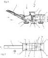
In den
Im Arbeitsbetrieb der Bodenfräsmaschine 1 stellen sich für den Maschinenführer zwei grundsätzliche Herausforderungen in Bezug auf die Positionsstabilität der Bodenfräsmaschine 1. Einerseits ist ein Auffräsen des Bodenuntergrundes in vorgegebener und kontrollierter Frästiefe gewünscht („Nivellierung“), um beispielsweise einen ausreichenden Oberflächenabtrag zu gewährleisten und tiefere Schichten des Straßenbetts gegebenenfalls nicht zu beschädigen. Andererseits neigen derartige Bodenfräsmaschinen aufgrund ihres hohen Schwerpunkts insbesondere beim Überfahren von Bodenhindernissen, wie beispielsweise von Fräskanten, zum vergleichsweise schnellen Umkippen. Um die Kippstabilität dieser Bodenfräsmaschinen 1 zu erhöhen, ist daher eine sogenannte „Pendelung“ vorgesehen, die im Sinne einer Pendelachse den gegenläufigen Höhenausgleich des Paares vorderer Fahreinrichtungen 5VR und 5VL und hinterer Fahreinrichtungen 5HR und 5HL und linker Fahreinrichtungen 5VL und 5HL und rechter Fahreinrichtungen 5VR und 5HR vorsieht und dadurch Bodenunebenheiten zum Maschinenrahmen 2 hin zumindest teilweise ausgleicht. Hierzu sind die Hubeinrichtungen 6 höhenverstellbar ausgebildet. Jede Hubeinrichtung 6 kann dazu beispielsweise ein in Form eines doppeltwirkenden Hydraulikzylinders ausgebildeten Aktor 10 aufweisen, dessen Aufbau und Funktionsweise in
Wie nachstehend noch weiter angegeben ist, ermöglicht das vorliegende System eine Steuerung der Hubverstellung der vorderen oder der hinteren Hubeinrichtungen in Abhängigkeit von einem Ist-Längsneigungswert des Maschinenrahmens 2 gegenüber einer Lotrichtung V. Zur Ermittlung eines Ist-Längsneigungswertes weist die Bodenfräsmaschine 1 einen Längsneigungssensor 13 auf. Dieser ist zur Ermittlung der aktuellen Neigung des LängsNeigungssensor 13 vorliegende Richtung der Schwerebeschleunigung. Die Längsneigung W bestimmt sich somit in einer virtuellen Bezugsebene, die durch die Längserstreckung L der Bodenfräsmaschine 1 in Vorwärts- bzw. Arbeitsrichtung A und die Lotrichtung V aufgespannt wird. Relevant ist die Ermittlung der Lage des Maschinenrahmens 2 in dieser virtuellen Referenzebene relativ zur Lotrichtung V und der Änderung dieser Anlage. Es kommt vorliegend nicht unbedingt auf die Ermittlung einer absoluten Winkelangabe an, sondern auf eine Änderung der Ist-Längsneigung gegenüber einer Soll-Längsneigung. Der tatsächliche Neigungswinkel kann dazu entlang eines Referenzstrahls ermittelt werden, der sich in der virtuellen Referenzebene erstreckt und beispielsweise parallel zur Längserstreckung des Maschinenrahmens oder aber auch senkrecht hierzu verläuft. Der Längsneigungssensor 13 kann direkt am Maschinenrahmen 2 gelagert sein oder auch beispielsweise im Fahrstand 7 positioniert sein.As will be specified further below, the present system enables the stroke adjustment of the front or rear lifting devices to be controlled as a function of an actual longitudinal inclination value of the
Der Grundaufbau möglicher Hubeinrichtungen ist beispielhaft in
Die Steuereinheit 18 ist dazu ausgebildet, dass sie im vorliegenden Fall insbesondere die Hublage der hinteren Hubeinrichtungen in Abhängigkeit von der Ist-Längsneigung hin zu einer definierten Soll-Längsneigung regelt.
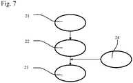
In den
Ein Vergleich der
Als Auslöseschwelle für den Schritt 23 kann ein funktional vorgelagerter Schritt 24 vorgesehen sein, der überwacht, ob die Abweichung der Ist-Längsneigung gegenüber der Soll-Längsneigung einen festgelegten Grenzwert und/oder ein Zeitintervall überschreitet. Erst beim Überschreiten des Grenzwertes erfolgt ein Nachregeln.A functionally
ZITATE ENTHALTEN IN DER BESCHREIBUNGQUOTES INCLUDED IN DESCRIPTION
Diese Liste der vom Anmelder aufgeführten Dokumente wurde automatisiert erzeugt und ist ausschließlich zur besseren Information des Lesers aufgenommen. Die Liste ist nicht Bestandteil der deutschen Patent- bzw. Gebrauchsmusteranmeldung. Das DPMA übernimmt keinerlei Haftung für etwaige Fehler oder Auslassungen.This list of documents cited by the applicant was generated automatically and is included solely for the better information of the reader. The list is not part of the German patent or utility model application. The DPMA assumes no liability for any errors or omissions.
Zitierte PatentliteraturPatent Literature Cited
- DE 102006062129 A1 [0002, 0016]DE 102006062129 A1 [0002, 0016]
- DE 102005044211 A1 [0002, 0016]DE 102005044211 A1 [0002, 0016]
- EP 1855899 B1 [0002, 0016]EP 1855899 B1 [0002, 0016]
- EP 2722441 B1 [0002, 0016]EP 2722441 B1 [0002, 0016]
- DE 102014019168 A1 [0002, 0016]DE 102014019168 A1 [0002, 0016]
- DE 102014019468 A1 [0015]DE 102014019468 A1 [0015]
Claims (10)
Translated fromGermanPriority Applications (2)
| Application Number | Priority Date | Filing Date | Title |
|---|---|---|---|
| US17/657,974US12128725B2 (en) | 2021-04-06 | 2022-04-05 | Method for setting the lift position of a machine frame of a ground milling machine, which machine frame is connected via lifting means to movement means, and ground milling machine |
| CN202210353053.6ACN115198610B (en) | 2021-04-06 | 2022-04-06 | Method for adjusting the lifting position of a frame of a floor milling machine connected to a travel device via a lifting device, and floor milling machine |
Applications Claiming Priority (2)
| Application Number | Priority Date | Filing Date | Title |
|---|---|---|---|
| DE102021001754 | 2021-04-06 | ||
| DE102021001754.4 | 2021-04-06 |
Publications (1)
| Publication Number | Publication Date |
|---|---|
| DE102021118775A1true DE102021118775A1 (en) | 2022-10-06 |
Family
ID=83282601
Family Applications (1)
| Application Number | Title | Priority Date | Filing Date |
|---|---|---|---|
| DE102021118775.3APendingDE102021118775A1 (en) | 2021-04-06 | 2021-07-20 | Method for adjusting the lifting position of a machine frame of a floor milling machine and floor milling machine connected via lifting devices to driving devices |
Country Status (3)
| Country | Link |
|---|---|
| US (1) | US12128725B2 (en) |
| CN (1) | CN115198610B (en) |
| DE (1) | DE102021118775A1 (en) |
Families Citing this family (1)
| Publication number | Priority date | Publication date | Assignee | Title |
|---|---|---|---|---|
| DE102019135668A1 (en)* | 2019-12-23 | 2021-06-24 | Wirtgen Gmbh | Self-propelled construction machine and method for controlling a self-propelled construction machine |
Citations (6)
| Publication number | Priority date | Publication date | Assignee | Title |
|---|---|---|---|---|
| DE102005044211A1 (en) | 2005-09-12 | 2007-03-22 | Wirtgen Gmbh | Self-propelled construction machine, as well as lifting column for a construction machine |
| DE102006062129A1 (en) | 2006-12-22 | 2008-07-24 | Wirtgen Gmbh | Road construction machine and method for measuring the cutting depth |
| EP1855899B1 (en) | 2005-03-10 | 2013-09-18 | Wirtgen GmbH | Road-building machine |
| DE102014019168A1 (en) | 2014-12-19 | 2016-06-23 | Bomag Gmbh | CONSTRUCTION MACHINE, PARTICULARLY ROAD TERMINAL, AND METHOD FOR COMPENSATING FLOOR INFLUENCE FOR SUCH A CONSTRUCTION MACHINE |
| EP2722441B1 (en) | 2012-10-19 | 2016-11-16 | Wirtgen GmbH | Self-propelled construction machine and method for operating the same |
| DE102016119356A1 (en) | 2015-10-13 | 2017-04-13 | Caterpillar Paving Products Inc. | SYSTEM AND METHOD FOR CONTROLLING THE STABILITY OF MILLING MACHINES |
Family Cites Families (13)
| Publication number | Priority date | Publication date | Assignee | Title |
|---|---|---|---|---|
| US5318378A (en)* | 1992-09-28 | 1994-06-07 | Caterpillar Paving Products Inc. | Method and apparatus for controlling a cold planer in response to a kickback event |
| DE102004040136B4 (en)* | 2004-08-19 | 2008-05-08 | Abg Allgemeine Baumaschinen-Gesellschaft Mbh | Device for milling traffic areas |
| DE102010014893A1 (en) | 2010-04-14 | 2011-10-20 | Bomag Gmbh | Device for processing ground surfaces |
| US8899689B2 (en)* | 2011-12-21 | 2014-12-02 | Caterpillar Paving Products Inc. | Automatic cut-transition milling machine and method |
| DE102013010298A1 (en)* | 2013-06-19 | 2014-12-24 | Bomag Gmbh | Construction machine, in particular road milling machine, and method for compensating for uneven floors for such a construction machine |
| DE102014005077A1 (en)* | 2014-04-04 | 2015-10-08 | Wirtgen Gmbh | Self-propelled construction machine and method for controlling a self-propelled construction machine |
| US9879386B2 (en)* | 2015-12-10 | 2018-01-30 | Caterpillar Paving Products Inc. | System for coordinating milling and paving machines |
| US10688901B2 (en) | 2016-03-23 | 2020-06-23 | Bomag Gmbh | Intermediate storage vehicle for milled material and work train |
| DE102017010238A1 (en) | 2017-11-03 | 2019-05-09 | Bomag Gmbh | Measurement of installation layer thickness by road roller |
| US11105051B2 (en)* | 2018-10-23 | 2021-08-31 | Caterpillar Paving Products Inc. | Inclination control for construction machines |
| CN109733492A (en) | 2018-12-29 | 2019-05-10 | 长安大学 | A kind of automatic leveling method of milling system |
| EP3795748B1 (en) | 2019-09-20 | 2022-08-31 | MOBA Mobile Automation AG | Levelling system for a road construction machine |
| CN110965442A (en) | 2019-12-11 | 2020-04-07 | 三一汽车制造有限公司 | Milling machine support leg lifting control system, milling machine and control method |
- 2021
- 2021-07-20DEDE102021118775.3Apatent/DE102021118775A1/enactivePending
- 2022
- 2022-04-05USUS17/657,974patent/US12128725B2/enactiveActive
- 2022-04-06CNCN202210353053.6Apatent/CN115198610B/enactiveActive
Patent Citations (6)
| Publication number | Priority date | Publication date | Assignee | Title |
|---|---|---|---|---|
| EP1855899B1 (en) | 2005-03-10 | 2013-09-18 | Wirtgen GmbH | Road-building machine |
| DE102005044211A1 (en) | 2005-09-12 | 2007-03-22 | Wirtgen Gmbh | Self-propelled construction machine, as well as lifting column for a construction machine |
| DE102006062129A1 (en) | 2006-12-22 | 2008-07-24 | Wirtgen Gmbh | Road construction machine and method for measuring the cutting depth |
| EP2722441B1 (en) | 2012-10-19 | 2016-11-16 | Wirtgen GmbH | Self-propelled construction machine and method for operating the same |
| DE102014019168A1 (en) | 2014-12-19 | 2016-06-23 | Bomag Gmbh | CONSTRUCTION MACHINE, PARTICULARLY ROAD TERMINAL, AND METHOD FOR COMPENSATING FLOOR INFLUENCE FOR SUCH A CONSTRUCTION MACHINE |
| DE102016119356A1 (en) | 2015-10-13 | 2017-04-13 | Caterpillar Paving Products Inc. | SYSTEM AND METHOD FOR CONTROLLING THE STABILITY OF MILLING MACHINES |
Also Published As
| Publication number | Publication date |
|---|---|
| CN115198610B (en) | 2024-07-30 |
| US20220314724A1 (en) | 2022-10-06 |
| US12128725B2 (en) | 2024-10-29 |
| CN115198610A (en) | 2022-10-18 |
Similar Documents
| Publication | Publication Date | Title |
|---|---|---|
| DE102014019168A1 (en) | CONSTRUCTION MACHINE, PARTICULARLY ROAD TERMINAL, AND METHOD FOR COMPENSATING FLOOR INFLUENCE FOR SUCH A CONSTRUCTION MACHINE | |
| EP2104768B1 (en) | Road milling machine, and method for positioning the machine frame parallel to the ground | |
| EP2987911B1 (en) | Self-propelled milling machine, and method for unloading milled goods | |
| EP2636794B1 (en) | Large-scale self-propelled milling machine for machining road surfaces and method for machining road surfaces | |
| DE2131650C3 (en) | Road paver with a frame supporting the production tools | |
| DE102013010298A1 (en) | Construction machine, in particular road milling machine, and method for compensating for uneven floors for such a construction machine | |
| EP3861170B1 (en) | Method for controlling a ground compaction machine and ground compaction machine | |
| DE102017005814A1 (en) | Method for aligning a ground milling machine to the ground and ground milling machine | |
| DE102017208558A1 (en) | Method and agricultural machine for distribution of crop | |
| DE102020005204A1 (en) | Method for regulating the height adjustment of a height-adjustable chassis of a self-propelled ground milling machine, in particular a road milling machine, and ground milling machine | |
| DE102018010153B4 (en) | Construction machine, in particular road milling machine, and a method for controlling the lifting position of a piston-cylinder unit of a lifting column of a construction machine | |
| EP3219187A1 (en) | Moveable device for dispensing fluid and/or solid substances and method for controlling the device | |
| DE102017002225A1 (en) | Road paver with control unit for determining the weight and / or the center of gravity and / or the width of the screed and method | |
| EP3587668B1 (en) | Self-propelled construction machine and method for processing floor linings | |
| DE19525673C1 (en) | Level regulation system for hydraulic supports for work platform | |
| DE102021118775A1 (en) | Method for adjusting the lifting position of a machine frame of a floor milling machine and floor milling machine connected via lifting devices to driving devices | |
| EP3489415B1 (en) | Self-propelled milling machine and method for automatically loading a means of transport with milled material | |
| DE102017002641A1 (en) | Intermediate storage vehicle for milled material and work train | |
| DE102019127847A1 (en) | EXTENSION TUBE ORIENTATION ON A EXTENDING SCREED DOUBLE SLIDE | |
| DE102021000333A1 (en) | Method for pivoting a driving device of a road milling machine and road milling machine | |
| EP3847324B1 (en) | Transport device for moving heavy loads | |
| DE102017113423B4 (en) | Device for leveled alignment/lifting of a vehicle, and method for operating a device for leveled lifting of a vehicle | |
| DE102018132377A1 (en) | Tillage machine | |
| EP4368481B1 (en) | Ground milling machine, method of driving a ground milling machine and method of positioning a ground milling machine | |
| DE102023131297A1 (en) | Self-propelled construction machine, in particular ground milling machine, and method for operating a construction machine |
Legal Events
| Date | Code | Title | Description |
|---|---|---|---|
| R163 | Identified publications notified | ||
| R082 | Change of representative | Representative=s name:ZIMMERMANN & PARTNER PATENTANWAELTE MBB, DE |