DE102021105438A1 - HEAT DISSIPATION DEVICE FOR LIQUID COOLING - Google Patents
HEAT DISSIPATION DEVICE FOR LIQUID COOLINGDownload PDFInfo
- Publication number
- DE102021105438A1 DE102021105438A1DE102021105438.9ADE102021105438ADE102021105438A1DE 102021105438 A1DE102021105438 A1DE 102021105438A1DE 102021105438 ADE102021105438 ADE 102021105438ADE 102021105438 A1DE102021105438 A1DE 102021105438A1
- Authority
- DE
- Germany
- Prior art keywords
- water
- mounting groove
- cooling
- box body
- chamber
- Prior art date
- Legal status (The legal status is an assumption and is not a legal conclusion. Google has not performed a legal analysis and makes no representation as to the accuracy of the status listed.)
- Granted
Links
Images


Classifications
- F—MECHANICAL ENGINEERING; LIGHTING; HEATING; WEAPONS; BLASTING
- F28—HEAT EXCHANGE IN GENERAL
- F28D—HEAT-EXCHANGE APPARATUS, NOT PROVIDED FOR IN ANOTHER SUBCLASS, IN WHICH THE HEAT-EXCHANGE MEDIA DO NOT COME INTO DIRECT CONTACT
- F28D1/00—Heat-exchange apparatus having stationary conduit assemblies for one heat-exchange medium only, the media being in contact with different sides of the conduit wall, in which the other heat-exchange medium is a large body of fluid, e.g. domestic or motor car radiators
- F28D1/02—Heat-exchange apparatus having stationary conduit assemblies for one heat-exchange medium only, the media being in contact with different sides of the conduit wall, in which the other heat-exchange medium is a large body of fluid, e.g. domestic or motor car radiators with heat-exchange conduits immersed in the body of fluid
- F28D1/03—Heat-exchange apparatus having stationary conduit assemblies for one heat-exchange medium only, the media being in contact with different sides of the conduit wall, in which the other heat-exchange medium is a large body of fluid, e.g. domestic or motor car radiators with heat-exchange conduits immersed in the body of fluid with plate-like or laminated conduits
- F28D1/0308—Heat-exchange apparatus having stationary conduit assemblies for one heat-exchange medium only, the media being in contact with different sides of the conduit wall, in which the other heat-exchange medium is a large body of fluid, e.g. domestic or motor car radiators with heat-exchange conduits immersed in the body of fluid with plate-like or laminated conduits the conduits being formed by paired plates touching each other
- F28D1/0316—Assemblies of conduits in parallel
- F—MECHANICAL ENGINEERING; LIGHTING; HEATING; WEAPONS; BLASTING
- F28—HEAT EXCHANGE IN GENERAL
- F28D—HEAT-EXCHANGE APPARATUS, NOT PROVIDED FOR IN ANOTHER SUBCLASS, IN WHICH THE HEAT-EXCHANGE MEDIA DO NOT COME INTO DIRECT CONTACT
- F28D1/00—Heat-exchange apparatus having stationary conduit assemblies for one heat-exchange medium only, the media being in contact with different sides of the conduit wall, in which the other heat-exchange medium is a large body of fluid, e.g. domestic or motor car radiators
- F28D1/02—Heat-exchange apparatus having stationary conduit assemblies for one heat-exchange medium only, the media being in contact with different sides of the conduit wall, in which the other heat-exchange medium is a large body of fluid, e.g. domestic or motor car radiators with heat-exchange conduits immersed in the body of fluid
- F28D1/04—Heat-exchange apparatus having stationary conduit assemblies for one heat-exchange medium only, the media being in contact with different sides of the conduit wall, in which the other heat-exchange medium is a large body of fluid, e.g. domestic or motor car radiators with heat-exchange conduits immersed in the body of fluid with tubular conduits
- F28D1/053—Heat-exchange apparatus having stationary conduit assemblies for one heat-exchange medium only, the media being in contact with different sides of the conduit wall, in which the other heat-exchange medium is a large body of fluid, e.g. domestic or motor car radiators with heat-exchange conduits immersed in the body of fluid with tubular conduits the conduits being straight
- F28D1/0535—Heat-exchange apparatus having stationary conduit assemblies for one heat-exchange medium only, the media being in contact with different sides of the conduit wall, in which the other heat-exchange medium is a large body of fluid, e.g. domestic or motor car radiators with heat-exchange conduits immersed in the body of fluid with tubular conduits the conduits being straight the conduits having a non-circular cross-section
- F28D1/05366—Assemblies of conduits connected to common headers, e.g. core type radiators
- F28D1/05375—Assemblies of conduits connected to common headers, e.g. core type radiators with particular pattern of flow, e.g. change of flow direction
- F—MECHANICAL ENGINEERING; LIGHTING; HEATING; WEAPONS; BLASTING
- F28—HEAT EXCHANGE IN GENERAL
- F28D—HEAT-EXCHANGE APPARATUS, NOT PROVIDED FOR IN ANOTHER SUBCLASS, IN WHICH THE HEAT-EXCHANGE MEDIA DO NOT COME INTO DIRECT CONTACT
- F28D1/00—Heat-exchange apparatus having stationary conduit assemblies for one heat-exchange medium only, the media being in contact with different sides of the conduit wall, in which the other heat-exchange medium is a large body of fluid, e.g. domestic or motor car radiators
- F28D1/02—Heat-exchange apparatus having stationary conduit assemblies for one heat-exchange medium only, the media being in contact with different sides of the conduit wall, in which the other heat-exchange medium is a large body of fluid, e.g. domestic or motor car radiators with heat-exchange conduits immersed in the body of fluid
- F28D1/03—Heat-exchange apparatus having stationary conduit assemblies for one heat-exchange medium only, the media being in contact with different sides of the conduit wall, in which the other heat-exchange medium is a large body of fluid, e.g. domestic or motor car radiators with heat-exchange conduits immersed in the body of fluid with plate-like or laminated conduits
- F28D1/0308—Heat-exchange apparatus having stationary conduit assemblies for one heat-exchange medium only, the media being in contact with different sides of the conduit wall, in which the other heat-exchange medium is a large body of fluid, e.g. domestic or motor car radiators with heat-exchange conduits immersed in the body of fluid with plate-like or laminated conduits the conduits being formed by paired plates touching each other
- F28D1/0325—Heat-exchange apparatus having stationary conduit assemblies for one heat-exchange medium only, the media being in contact with different sides of the conduit wall, in which the other heat-exchange medium is a large body of fluid, e.g. domestic or motor car radiators with heat-exchange conduits immersed in the body of fluid with plate-like or laminated conduits the conduits being formed by paired plates touching each other the plates having lateral openings therein for circulation of the heat-exchange medium from one conduit to another
- F28D1/0333—Heat-exchange apparatus having stationary conduit assemblies for one heat-exchange medium only, the media being in contact with different sides of the conduit wall, in which the other heat-exchange medium is a large body of fluid, e.g. domestic or motor car radiators with heat-exchange conduits immersed in the body of fluid with plate-like or laminated conduits the conduits being formed by paired plates touching each other the plates having lateral openings therein for circulation of the heat-exchange medium from one conduit to another the plates having integrated connecting members
- F28D1/0341—Heat-exchange apparatus having stationary conduit assemblies for one heat-exchange medium only, the media being in contact with different sides of the conduit wall, in which the other heat-exchange medium is a large body of fluid, e.g. domestic or motor car radiators with heat-exchange conduits immersed in the body of fluid with plate-like or laminated conduits the conduits being formed by paired plates touching each other the plates having lateral openings therein for circulation of the heat-exchange medium from one conduit to another the plates having integrated connecting members with U-flow or serpentine-flow inside the conduits
- F—MECHANICAL ENGINEERING; LIGHTING; HEATING; WEAPONS; BLASTING
- F28—HEAT EXCHANGE IN GENERAL
- F28D—HEAT-EXCHANGE APPARATUS, NOT PROVIDED FOR IN ANOTHER SUBCLASS, IN WHICH THE HEAT-EXCHANGE MEDIA DO NOT COME INTO DIRECT CONTACT
- F28D1/00—Heat-exchange apparatus having stationary conduit assemblies for one heat-exchange medium only, the media being in contact with different sides of the conduit wall, in which the other heat-exchange medium is a large body of fluid, e.g. domestic or motor car radiators
- F28D1/02—Heat-exchange apparatus having stationary conduit assemblies for one heat-exchange medium only, the media being in contact with different sides of the conduit wall, in which the other heat-exchange medium is a large body of fluid, e.g. domestic or motor car radiators with heat-exchange conduits immersed in the body of fluid
- F28D1/0233—Heat-exchange apparatus having stationary conduit assemblies for one heat-exchange medium only, the media being in contact with different sides of the conduit wall, in which the other heat-exchange medium is a large body of fluid, e.g. domestic or motor car radiators with heat-exchange conduits immersed in the body of fluid with air flow channels
- F28D1/024—Heat-exchange apparatus having stationary conduit assemblies for one heat-exchange medium only, the media being in contact with different sides of the conduit wall, in which the other heat-exchange medium is a large body of fluid, e.g. domestic or motor car radiators with heat-exchange conduits immersed in the body of fluid with air flow channels with an air driving element
- F—MECHANICAL ENGINEERING; LIGHTING; HEATING; WEAPONS; BLASTING
- F28—HEAT EXCHANGE IN GENERAL
- F28F—DETAILS OF HEAT-EXCHANGE AND HEAT-TRANSFER APPARATUS, OF GENERAL APPLICATION
- F28F1/00—Tubular elements; Assemblies of tubular elements
- F28F1/10—Tubular elements and assemblies thereof with means for increasing heat-transfer area, e.g. with fins, with projections, with recesses
- F28F1/12—Tubular elements and assemblies thereof with means for increasing heat-transfer area, e.g. with fins, with projections, with recesses the means being only outside the tubular element
- F28F1/126—Tubular elements and assemblies thereof with means for increasing heat-transfer area, e.g. with fins, with projections, with recesses the means being only outside the tubular element consisting of zig-zag shaped fins
- F—MECHANICAL ENGINEERING; LIGHTING; HEATING; WEAPONS; BLASTING
- F28—HEAT EXCHANGE IN GENERAL
- F28F—DETAILS OF HEAT-EXCHANGE AND HEAT-TRANSFER APPARATUS, OF GENERAL APPLICATION
- F28F9/00—Casings; Header boxes; Auxiliary supports for elements; Auxiliary members within casings
- F—MECHANICAL ENGINEERING; LIGHTING; HEATING; WEAPONS; BLASTING
- F28—HEAT EXCHANGE IN GENERAL
- F28F—DETAILS OF HEAT-EXCHANGE AND HEAT-TRANSFER APPARATUS, OF GENERAL APPLICATION
- F28F2250/00—Arrangements for modifying the flow of the heat exchange media, e.g. flow guiding means; Particular flow patterns
- F28F2250/08—Fluid driving means, e.g. pumps, fans
- F—MECHANICAL ENGINEERING; LIGHTING; HEATING; WEAPONS; BLASTING
- F28—HEAT EXCHANGE IN GENERAL
- F28F—DETAILS OF HEAT-EXCHANGE AND HEAT-TRANSFER APPARATUS, OF GENERAL APPLICATION
- F28F2275/00—Fastening; Joining
- F28F2275/06—Fastening; Joining by welding
Landscapes
- Engineering & Computer Science (AREA)
- Physics & Mathematics (AREA)
- Thermal Sciences (AREA)
- Mechanical Engineering (AREA)
- General Engineering & Computer Science (AREA)
- Geometry (AREA)
- Structures Of Non-Positive Displacement Pumps (AREA)
- Cooling Or The Like Of Electrical Apparatus (AREA)
- Heat-Exchange Devices With Radiators And Conduit Assemblies (AREA)
Abstract
Translated fromGerman
Description
Translated fromGermanTechnisches Gebiettechnical field
Die vorliegende Erfindung betrifft eine Wärmeableitvorrichtung, insbesondere eine Wärmeableitvorrichtung zur Flüssigkeitskühlung.The present invention relates to a heat dissipation device, in particular a heat dissipation device for liquid cooling.
Stand der TechnikState of the art
Ein Wasserkühlungsradiator ist so konfiguriert, dass er die Wärme des Radiators mit Hilfe einer Flüssigkeit unter der Wirkung einer Pumpe abstrahlt. Im Vergleich zur Luftkühlung weist der Wasserkühlungsradiator die Vorteile eines geräuscharmen Betriebs, der stabilen Kühlung und der geringeren Abhängigkeit von der Umwelt auf. Die Leistung der Wärmeableitung des Wasserkühlungsradiators ist proportional zur Durchflussmenge einer Kühlflüssigkeit (Wasser oder andere Flüssigkeit). Die Durchflussmenge der Kühlflüssigkeit steht im Zusammenhang mit der Leistung der Pumpe im Kühlsystem. Außerdem verfügt das Wasser über eine große Wärmekapazität. Dadurch weist das Wasserkühlsystem eine gute Wärmelastfähigkeit auf.A water-cooling radiator is configured to radiate the heat of the radiator using a liquid under the action of a pump. Compared with air cooling, the water cooling radiator has the advantages of low noise operation, stable cooling and less dependence on the environment. The heat dissipation performance of the water cooling radiator is proportional to the flow rate of a cooling liquid (water or other liquid). The flow rate of the coolant is related to the performance of the pump in the cooling system. In addition, water has a large heat capacity. As a result, the water cooling system has good thermal load capacity.
Eine Baugruppe eines Wasserkühlungsradiators nach dem Stand der Technik ist üblicherweise aus einem Wasserkühlungsradiator, einem Wasserkühlungsblock und einer Wasserleitung aufgebaut. Die Wasserleitung ist zwischen dem Wasserkühlungsradiator und dem Wasserkühlungsblock angeschlossen. Die Wasserleitung ermöglicht die Zirkulation des Wassers im Wasserkühlungsradiator und im Wasserkühlungsblock. Nachdem das Wasser die Wärme aus dem Wasserkühlungsblock aufgenommen hat, fließt das Wasser zur Wärmeableitung zum Wasserkühlungsradiator, wonach das Wasser nach der Wärmeableitung zurück zum Wasserkühlungsblock fließt.A prior art water cooling radiator assembly is usually made up of a water cooling radiator, a water cooling block and a water pipe. The water pipe is connected between the water cooling radiator and the water cooling block. The water pipe enables the water to circulate in the water cooling radiator and the water cooling block. After the water absorbs the heat from the water cooling block, the water flows to the water cooling radiator for heat dissipation, after which the water flows back to the water cooling block after heat dissipation.
Nach dem Stand der Technik sind die Kanäle des Wasserkühlungsradiators der Baugruppe des Wasserkühlungsradiators U-förmig. Dies führt dazu, dass das Wasser im Wasserkühlungsradiator einen kurzen Weg zurücklegt, so dass der Wasserkühlungsradiator das Wasser nicht effektiv abkühlen und die Wärme ableiten kann. Die Durchflussrate des Wassers im Wasserkühlungsradiator ist langsamer und die Effizienz der Wärmeableitung geringer. Daher bedarf es einer Ausbesserung des Wasserkühlungsradiators nach dem Stand der Technik.According to the prior art, the channels of the water cooling radiator of the assembly of the water cooling radiator are U-shaped. This causes the water in the water cooling radiator to travel a short distance, so the water cooling radiator cannot effectively cool the water and dissipate the heat. The flow rate of water in the water cooling radiator is slower and the heat dissipation efficiency is lower. Therefore, there is a need for a repair of the water cooling radiator according to the state of the art.
Aufgabe der Erfindungobject of the invention
Angesichts der Nachteile des Stands der Technik besteht das Hauptziel der vorliegenden Erfindung in der Schaffung einer Wärmeableitvorrichtung zur Flüssigkeitskühlung, mit der das Problem des Wasserkühlungsradiators nach dem Stand der Technik, dass das Wasser nicht effektiv abgekühlt und die Wärme abgeleitet werden kann, effektiv gelöst werden kann.In view of the disadvantages of the prior art, the main object of the present invention is to provide a liquid cooling heat dissipation device which can effectively solve the problem of the prior art water cooling radiator that the water cannot be effectively cooled and the heat dissipated .
Zum Erreichen des oben genannten Ziels werden mit der vorliegenden Erfindung die folgenden technischen Lösungen geschaffen:
- Eine Wärmeableitvorrichtung zur Flüssigkeitskühlung umfasst einen Wasserverteilkasten, einen Wasserauffangbehälter, ein erstes Kühlrohr, ein zweites Kühlrohr, ein drittes Kühlrohr, ein viertes Kühlrohr und eine Pumpvorrichtung.
- A heat dissipation device for liquid cooling includes a water distribution box, a water receiver, a first cooling pipe, a second cooling pipe, a third cooling pipe, a fourth cooling pipe, and a pumping device.
Der Wasserverteilkasten besteht aus einem wärmeableitenden Metallmaterial. Mehrere erste Trennwände sind im Wasserverteilkasten vorgesehen, um einen Innenraum des Wasserverteilkastens in eine Wasserzulaufkammer, eine Übergangskammer und eine Wasserablaufkammer zu unterteilen. Der Wasserverteilkasten ist mit einem Wasserzulauf, Wasserablauf, einer ersten Montagenut, einer zweiten Montagenut und einer dritten Montagenut gebildet. Der Wasserzulauf und die erste Montagenut sind mit der Wasserzulaufkammer verbunden. Der Wasserablauf und die zweite Montagenut sind mit der Wasserablaufkammer verbunden. Die dritte Montagenut ist mit der Übergangskammer verbunden.The water distribution box is made of heat-dissipating metal material. A plurality of first partitions are provided in the water distribution box to divide an interior space of the water distribution box into a water supply chamber, a transition chamber, and a water drainage chamber. The water distribution box is formed with a water inlet, a water outlet, a first mounting groove, a second mounting groove and a third mounting groove. The water inlet and the first mounting groove are connected to the water inlet chamber. The water drain and the second mounting groove are connected to the water drain chamber. The third mounting groove is connected to the transition chamber.
Der Wasserauffangbehälter besteht aus einem wärmeableitenden Metallmaterial. Mindestens eine zweite Trennwand ist im Wasserauffangbehälter vorgesehen, um einen Innenraum des Wasserauffangbehälters in eine erste Wasserauffangkammer und eine zweite Wasserauffangkammer zu unterteilen. Der Wasserauffangbehälter weist eine vierte Montagenut und eine fünfte Montagenut auf. Die vierte Montagenut ist mit der ersten Wasserauffangkammer verbunden. Die fünfte Montagenut ist mit der zweiten Wasserauffangkammer verbunden.The water collection tank is made of heat-dissipating metal material. At least one second partition is provided in the water tank to divide an interior space of the water tank into a first water tank and a second water tank. The water catchment tank has a fourth mounting groove and a fifth mounting groove. The fourth mounting groove is connected to the first water-collecting chamber. The fifth mounting groove is connected to the second water collecting chamber.
Das erste Kühlrohr, das zweite Kühlrohr, das dritte Kühlrohr und das vierte Kühlrohr sind mit Kühlrippen gebildet. Ein Ende des ersten Kühlrohrs ist hermetisch in der ersten Montagenut befestigt und mit der Wasserzulaufkammer verbunden. Ein anderes Ende des ersten Kühlrohrs ist hermetisch in der vierten Montagenut befestigt und mit der ersten Wasserauffangkammer verbunden. Ein Ende des zweiten Kühlrohrs ist hermetisch in der dritten Montagenut befestigt und mit der Übergangskammer verbunden. Ein anderes Ende des zweiten Kühlrohrs ist hermetisch in der vierten Montagenut befestigt und mit der ersten Wasserauffangkammer verbunden. Ein Ende des dritten Kühlrohrs ist hermetisch in der dritten Montagenut befestigt und mit der Übergangskammer verbunden. Ein anderes Ende des dritten Kühlrohrs ist hermetisch in der fünften Montagenut befestigt und mit der zweiten Wasserauffangkammer verbunden. Das dritte Kühlrohr ist in mindestens zwei Abschnitte unterteilt. Ein Ende des vierten Kühlrohrs ist hermetisch in der zweiten Montagenut befestigt und mit der Wasserablaufkammer verbunden. Ein anderes Ende des vierten Kühlrohrs ist hermetisch in der fünften Montagenut befestigt und mit der zweiten Wasserauffangkammer verbunden.The first cooling pipe, the second cooling pipe, the third cooling pipe, and the fourth cooling pipe are formed with cooling fins. One end of the first cooling pipe is hermetically fixed in the first mounting groove and connected to the water inlet chamber. Another end of the first cooling pipe is hermetically fixed in the fourth mounting groove and connected to the first water trap chamber. One end of the second cooling tube is hermetically fixed in the third mounting groove and connected to the transition chamber. Another end of the second cooling pipe is hermetically fixed in the fourth mounting groove and connected to the first water trap chamber. An end of the third cooling tube is hermetically fixed in the third mounting groove and connected to the transition chamber. Another end of the third cooling tube is hermetically fixed in the fifth mounting groove and connected to the second water catchment chamber connected. The third cooling tube is divided into at least two sections. One end of the fourth cooling pipe is hermetically fixed in the second mounting groove and connected to the water drain chamber. Another end of the fourth cooling pipe is hermetically fixed in the fifth mounting groove and connected to the second water trap chamber.
Die Pumpvorrichtung ist einstückig zwischen den beiden benachbarten Abschnitten des dritten Kühlrohrs angeordnet. Die Pumpvorrichtung besteht aus einem Hauptkastengehäuse und einem Wasserpumpendeckel. Das Hauptkastengehäuse besteht aus einem wärmeableitenden Metallmaterial. Im Hauptkastengehäuse ist ein Wasserpumpenraum gebildet. Eine Haupttrennwand ist im Hauptkastengehäuse vorgesehen, um einen Innenraum des Hauptkastengehäuses in einen Wasserzulaufhohlraum und einen Wasserablaufhohlraum zu unterteilen. Der Wasserablaufhohlraum ist mit dem Wasserpumpenraum verbunden. Auf einer Seite des Hauptkastengehäuses ist eine sechste Montagenut gebildet, die mit dem Wasserzulaufhohlraum verbunden ist. Auf einer anderen Seite des Hauptkastengehäuses ist eine siebte Montagenut gebildet, die mit dem Wasserablaufhohlraum verbunden ist. Die Enden der beiden benachbarten Abschnitte des dritten Kühlrohrs sind hermetisch in der sechsten Montagenut und in der siebten Montagenut befestigt, um mit dem Wasserzulaufhohlraum bzw. dem Wasserablaufhohlraum verbunden zu sein. Ein Wasserpumpendeckel ist am Hauptkastengehäuse befestigt und zum Abdichten einer Öffnung des Wasserpumpenraums konfiguriert. Eine Wasserpumpe ist an einer Innenseite des Wasserpumpendeckels befestigt. Ein Laufrad ist an einer Antriebswelle der Wasserpumpe befestigt. Das Laufrad ist im Wasserpumpenraum montiert und wird zum Drehen durch die Wasserpumpe angetrieben.The pumping device is arranged in one piece between the two adjacent sections of the third cooling tube. The pumping device consists of a main box body and a water pump cover. The main box body is made of heat-dissipating metal material. A water pump room is formed in the main box body. A main partition wall is provided in the main box body to divide an interior space of the main box body into a water inlet cavity and a water outlet cavity. The water drain cavity is connected to the water pump room. A sixth mounting groove is formed on one side of the main box body and communicates with the water inlet cavity. On another side of the main box body, a seventh mounting groove is formed that connects to the water drain cavity. The ends of the two adjacent sections of the third cooling tube are hermetically fixed in the sixth mounting groove and in the seventh mounting groove to be connected to the water inlet cavity and the water outlet cavity, respectively. A water pump cover is attached to the main box body and configured to seal an opening of the water pump compartment. A water pump is attached to an inside of the water pump cover. An impeller is fixed to a drive shaft of the water pump. The impeller is mounted in the water pump room and is driven to rotate by the water pump.
Im Vergleich mit dem Stand der Technik weist die vorliegende Erfindung offensichtliche Vorteile und vorteilhafte Effekte auf. Insbesondere werden anhand der oben genannten technischen Lösungen die folgenden Vorteile offensichtlich:
- Durch Trennwände sowohl im Wasserverteilkasten als auch im Wasserauffangbehälter sind mehrere Kammern gebildet, wobei jedes Kühlrohr mit den jeweiligen Kammern verbunden ist, so dass die Kanäle in diesem Produkt hintereinander verbunden sind, um eine kreisförmige Konfiguration zu bilden. Dadurch legt das Wasser einen längeren Weg im Wasserkühlungsradiator zurück, so dass das Wasser im Wasserkühlungsradiator effektiv abgekühlt und die Wärme abgeleitet werden kann. Weiter kann der Wasserfluss mit einer Pumpvorrichtung effektiv beschleunigt und die Effizienz der Wärmeableitung verbessert werden. Die allgemeine Wärmeableitung des Produkts ist sehr gut.
- Multiple chambers are formed by partitions in both the water distribution box and the water collection tank, with each cooling tube connected to the respective chambers, so that the channels in this product are connected in series to form a circular configuration. As a result, the water travels a longer path in the water cooling radiator, so that the water in the water cooling radiator can be effectively cooled and the heat can be dissipated. Further, with a pumping device, the water flow can be effectively accelerated and the heat dissipation efficiency can be improved. The overall heat dissipation of the product is very good.
Figurenlistecharacter list
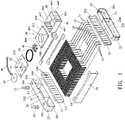
1 zeigt eine Explosionsansicht nach einem ersten Ausführungsbeispiel der vorliegenden Erfindung;1 Fig. 12 shows an exploded view according to a first embodiment of the present invention;2 zeigt eine Draufsicht nach dem ersten Ausführungsbeispiel der vorliegenden Erfindung;2 Fig. 12 shows a plan view according to the first embodiment of the present invention;3 zeigt eine Teilexplosionsansicht nach dem ersten Ausführungsbeispiel der vorliegenden Erfindung;3 Fig. 12 shows a partially exploded view according to the first embodiment of the present invention;4 zeigt eine perspektivische Ansicht nach dem ersten Ausführungsbeispiel der vorliegenden Erfindung bei der Verwendung;4 Fig. 14 is a perspective view of the first embodiment of the present invention in use;5 zeigt eine Draufsicht der4 ;5 shows a top view of the4 ;6 zeigt eine Explosionsansicht nach einem zweiten Ausführungsbeispiel der vorliegenden Erfindung;6 Fig. 12 shows an exploded view according to a second embodiment of the present invention;7 zeigt eine Draufsicht nach dem zweiten Ausführungsbeispiel der vorliegenden Erfindung;7 Fig. 12 shows a plan view according to the second embodiment of the present invention;8 zeigt eine Teilexplosionsansicht nach dem zweiten Ausführungsbeispiel der vorliegenden Erfindung;8th Fig. 14 shows a partially exploded view according to the second embodiment of the present invention;9 zeigt eine perspektivische Ansicht nach dem zweiten Ausführungsbeispiel der vorliegenden Erfindung bei der Verwendung; und9 Fig. 14 is a perspective view of the second embodiment of the present invention in use; and10 zeigt eine Draufsicht der9 .10 shows a top view of the9 .
Wege zur Ausführung der ErfindungWays to carry out the invention
Die
Der Wasserverteilkasten 10 besteht aus einem wärmeableitenden Metallmaterial. Inwendig im Wasserverteilkasten 10 sind mehrere erste Trennwände 11 vorgesehen, um den Innenraum des Wasserverteilkastens 10 in eine Wasserzulaufkammer 101, eine Übergangskammer 102 und eine Wasserablaufkammer 103 zu unterteilen. Der Wasserverteilkasten 10 ist mit einem Wasserzulauf 104, einem Wasserablauf 105, einer ersten Montagenut 106, einer zweiten Montagenut 107 und einer dritten Montagenut 108 gebildet. Der Wasserzulauf 104 und die erste Montagenut 106 sind mit der Wasserzulaufkammer 101 verbunden. Der Wasserablauf 105 und die zweite Montagenut 107 sind mit der Wasserablaufkammer 103 verbunden. Die dritte Montagenut 108 ist mit der Übergangskammer 102 verbunden. Insbesondere umfasst der Wasserverteilkasten 10 ein erstes Kastengehäuse 12 und einen ersten Kastendeckel 13. Die ersten Trennwände 11 sind durch Schweißen im ersten Kastengehäuse 12 oder einstückig mit dem ersten Kastengehäuse 12 gebildet. Der erste Kastendeckel 13 und das erste Kastengehäuse 12 sind hermetisch aneinander befestigt, um die Wasserzulaufkammer 101, die Übergangskammer 102 und die Wasserablaufkammer 103 zu bilden. Der Wasserzulauf 104 und der Wasserablauf 105 sind am ersten Kastengehäuse 12 gebildet. Eine Wasserzulauf-Rohrverbindung 51 ist hermetisch am Wasserzulauf 104 befestigt. Eine Wasserablauf-Rohrverbindung 52 ist hermetisch am Wasserablauf 105 befestigt. Die erste Montagenut 106, die zweite Montagenut 107 und die dritte Montagenut 108 sind am ersten Kastendeckel 13 gebildet. Die Wasserzulauf-Rohrverbindung 51 ist in den Wasserzulauf 104 eingesetzt und durch Schweißen hermetisch am ersten Kastengehäuse 12 befestigt. Die Wasserablauf-Rohrverbindung 52 ist in den Wasserablauf 105 eingesetzt und durch Schweißen hermetisch am ersten Kastengehäuse 12 befestigt. Das erste Kastengehäuse 12 und der erste Kastendeckel 13 bestehen aus Kupfer oder Aluminium. Der erste Kastendeckel 13 ist durch Schweißen hermetisch am ersten Kastengehäuse 12 befestigt.The
Der Wasserauffangbehälter 20 besteht aus einem wärmeableitenden Metallmaterial. Mindestens eine zweite Trennwand 21 ist im Wasserauffangbehälter 20 vorgesehen, um den Innenraum des Wasserauffangbehälters 20 in eine erste Wasserauffangkammer 201 und zweite Wasserauffangkammer 202 zu unterteilen. Der Wasserauffangbehälter 20 ist mit einer vierten Montagenut 203 und einer fünften Montagenut 204 gebildet. Die vierte Montagenut 203 ist mit der ersten Wasserauffangkammer 201 verbunden. Die fünfte Montagenut 204 ist mit der zweiten Wasserauffangkammer 202 verbunden. Insbesondere umfasst der Wasserauffangbehälter 20 ein zweites Kastengehäuse 22 und einen zweiten Kastendeckel 23. Die zweite Trennwand 21 ist durch Schweißen im zweiten Kastengehäuse 22 oder einstückig mit dem zweiten Kastengehäuse 22 gebildet. Der zweite Kastendeckel 23 und das zweite Kastengehäuse 22 sind hermetisch aneinander befestigt, um die erste Wasserauffangkammer 201 und die zweite Wasserauffangkammer 202 zu bilden. Die vierte Montagenut 203 und die fünfte Montagenut 204 sind am zweiten Kastendeckel 23 gebildet. Das zweite Kastengehäuse 22 und der zweite Kastendeckel 23 bestehen aus Kupfer oder Aluminium. Der zweite Kastendeckel 23 ist durch Schweißen hermetisch am zweiten Kastengehäuse 22 befestigt.The
Das erste Kühlrohr 31, das zweite Kühlrohr 32, das dritte Kühlrohr 33 und das vierte Kühlrohr 34 sind mit Kühlrippen 60 gebildet. In diesem Ausführungsbeispiel sind das erste Kühlrohr 31, das zweite Kühlrohr 32, das dritte Kühlrohr und das vierte Kühlrohr 34 als Flachrohre aus wärmeableitendem Metall gebildet. Sie können selbstverständlich auch Rundrohre aus wärmeableitendem Metall sein, wobei dies nicht darauf beschränkt ist. Beide Enden des ersten Kühlrohrs 31, zweiten Kühlrohrs 32, dritten Kühlrohrs 33 und des vierten Kühlrohrs 34 sind durch Schweißen am Wasserverteilkasten 10 bzw. am Wasserauffangbehälter 20 befestigt.The
Ein Ende des ersten Kühlrohrs 31 ist hermetisch in der ersten Montagenut 106 befestigt und mit der Wasserzulaufkammer 101 verbunden, während das andere Ende des ersten Kühlrohrs 31 hermetisch in der vierten Montagenut 203 befestigt und mit der ersten Wasserauffangkammer 201 verbunden ist. In diesem Ausführungsbeispiel weist das erste Kühlrohr 31 zwei erste Kühlrohre auf, die in einem Abstand nebeneinander angeordnet sind, wobei dies nicht darauf beschränkt ist.One end of the
Ein Ende des zweiten Kühlrohrs 32 ist hermetisch in der dritten Montagenut 108 befestigt und mit der Übergangskammer 102 verbunden, während das andere Ende des zweiten Kühlrohrs 32 hermetisch in der vierten Montagenut 203 befestigt und mit der ersten Wasserauffangkammer 201 verbunden ist. In diesem Ausführungsbeispiel weist das zweite Kühlrohr 32 zwei zweite Kühlrohre auf, die in einem Abstand nebeneinander angeordnet sind, wobei dies nicht darauf beschränkt ist.One end of the
Ein Ende des dritten Kühlrohrs 33 ist hermetisch in der dritten Montagenut 108 befestigt und mit der Übergangskammer 102 verbunden, während das andere Ende des dritten Kühlrohrs 33 hermetisch in der fünften Montagenut 204 befestigt und mit der zweiten Wasserauffangkammer 202 verbunden ist. Das dritte Kühlrohr 33 ist in mindestens zwei Abschnitte unterteilt. In diesem Ausführungsbeispiel ist das dritte Kühlrohr 33 in vordere und hintere zwei Abschnitte unterteilt. In diesem Ausführungsbeispiel weist das dritte Kühlrohr 33 vier dritte Kühlrohre auf, die in einem Abstand nebeneinander angeordnet sind, wobei dies nicht darauf beschränkt ist.One end of the
Ein Ende des vierten Kühlrohrs 34 ist hermetisch in der zweiten Montagenut 107 befestigt und mit der Wasserablaufkammer 103 verbunden, während das andere Ende des vierten Kühlrohrs 34 hermetisch in der fünften Montagenut 204 befestigt und mit der zweiten Wasserauffangkammer 202 verbunden ist. In diesem Ausführungsbeispiel weist das vierte Kühlrohr 34 vier vierte Kühlrohre auf, die in einem Abstand nebeneinander angeordnet sind, wobei dies nicht darauf beschränkt ist.One end of the
Die Pumpvorrichtung 40 ist einstückig zwischen den beiden benachbarten Abschnitten des dritten Kühlrohrs 33 angeordnet. Die Pumpvorrichtung 40 besteht aus einem Hauptkastengehäuse 41 und einem Wasserpumpendeckel 42. Das Hauptkastengehäuse 41 besteht ebenfalls aus einem wärmeableitenden Metallmaterial. Ein Wasserpumpenraum 401 ist im Hauptkastengehäuse 41 gebildet. Eine Haupttrennwand 43 ist im Hauptkastengehäuse 41 vorgesehen, um den Innenraum des Hauptkastengehäuses 41 in einen Wasserzulaufhohlraum 402 und einen Wasserablaufhohlraum 403 zu unterteilen. Der Wasserablaufhohlraum 403 ist mit dem Wasserpumpenraum 401 verbunden. Auf einer Seite des Hauptkastengehäuses 41 ist eine sechste Montagenut 404 gebildet, die mit dem Wasserzulaufhohlraum 402 verbunden ist. Auf der anderen Seite des Hauptkastengehäuses 41 ist eine siebte Montagenut 405 gebildet, die mit dem Wasserablaufhohlraum 403 verbunden ist. Die Enden der beiden benachbarten Abschnitte des dritten Kühlrohrs 33 sind hermetisch in der sechsten Montagenut 404 bzw. in der siebten Montagenut 405 befestigt, um mit dem Wasserzulaufhohlraum 402 bzw. dem Wasserablaufhohlraum 403 verbunden zu sein. Der Wasserpumpendeckel 42 ist am Hauptkastengehäuse 41 befestigt und zum Abdichten der Öffnung des Wasserpumpenraums 401 konfiguriert. Eine Wasserpumpe 44 ist an der Innenseite des Wasserpumpendeckels 42 befestigt. Ein Laufrad 45 ist an einer Antriebswelle der Wasserpumpe 44 befestigt. Das Laufrad 45 ist im Wasserpumpenraum 401 montiert und wird zum Drehen durch die Wasserpumpe 44 angetrieben.The
In diesem Ausführungsbeispiel besteht das Hauptkastengehäuse 41 aus einem unteren Kasten 411 und einer oberen Abdeckung 412. Die Haupttrennwand 43 ist durch Schweißen im unteren Kasten 411 oder einstückig mit dem unteren Kasten 411 gebildet. Der Wasserzulaufhohlraum 402 und der Wasserablaufhohlraum 403 sind im unteren Kasten 411 gebildet. Der Wasserzulaufhohlraum 402 und der Wasserablaufhohlraum 403 weisen nach oben gerichtete Öffnungen auf. Die sechste Montagenut 404 und die siebte Montagenut 405 sind je auf zwei Seiten des unteren Kastens 411 gebildet. Die obere Abdeckung 412 ist am unteren Kasten 411 befestigt und zum Abdichten und Abdecken der Öffnungen des Wasserzulaufhohlraums 402 und des Wasserablaufhohlraums 403 konfiguriert. Die obere Abdeckung 412 ist mit dem Wasserpumpenraum 401 gebildet. Jede Ecke der oberen Abdeckung 412 weist ein erstes Befestigungsloch 406 auf. Jede Ecke des unteren Kastens 411 weist ein zweites Befestigungsloch 407 auf. Eine Befestigungsschraube ist durch das erste Befestigungsloch 406 und das zweite Befestigungsloch 407 eingeschraubt, um die obere Abdeckung 412 und den unteren Kasten 411 aneinander zu befestigen. Der Wasserpumpendeckel 42 ist hermetisch an der oberen Abdeckung 412 befestigt. In diesem Ausführungsbeispiel ist ein Dichtungsring 46 zwischen dem Wasserpumpendeckel 42 und der oberen Abdeckung 412 eingeklemmt. Oben ist die obere Abdeckung 412 vertieft, um den Wasserpumpenraum 401 zu bilden. Der Innenboden des Wasserpumpenraums 401 weist ein erstes Durchgangsloch 408 auf. Das erste Durchgangsloch 408 ist mit dem Wasserzulaufhohlraum 402 verbunden. Die innere umlaufende Seitenwand des Wasserpumpenraums 401 weist ein zweites Durchgangsloch 409 auf. Die Haupttrennwand 43 weist ein drittes Durchgangsloch 431 auf. Das dritte Durchgangsloch 431 ist dem zweiten Durchgangsloch 409 zugewandt und mit diesem verbunden. Oben weist der Wasserpumpendeckel 42 eine Aussparung 421 auf. Eine Leiterplatte 47 ist in die Aussparung 421 eingesetzt. Die Leiterplatte 47 ist elektrisch mit der Wasserpumpe 44 verbunden. Die Leiterplatte 47 ist mit einem Stromkabel 48 angeschlossen. Das Stromkabel 48 ist zum Anschließen an eine externe Stromquelle konfiguriert.In this embodiment, the
Weiter sind zwei Lüfterhalterungen 70 zwischen dem Wasserverteilkasten 10 und dem Wasserauffangbehälter 20 montiert. Die beiden Lüfterhalterungen 70 sind beidseitig symmetrisch. Das erste Kühlrohr 31, das zweite Kühlrohr 32, das dritte Kühlrohr 33 und das vierte Kühlrohr 34 sind zwischen den beiden Lüfterhalterungen 70 angeordnet, damit der Gesamtaufbau des Produkts stabiler ist und ein Lüfter installiert und befestigt werden kann.Furthermore, two fan mounts 70 are mounted between the
Das Funktionsprinzip dieses Ausführungsbeispiels wird im Detail wie folgt beschrieben:
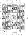
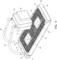
Die 4 und5 zeigen, dass beim Betrieb die Wasserzulauf-Rohrverbindung 51 und die Wasserablauf-Rohrverbindung 52mit einem Wasserzulaufrohr 81 bzw.einem Wasserablaufrohr 82 verbunden sind.Das Wasserzulaufrohr 81und das Wasserablaufrohr 82 sind je mit einem Ablauf bzw. einem Zulauf eines Wasserkühlungsblocks 83 verbunden.Ein elektronisches Bauteil 84ist am Wasserkühlungsblock 83 befestigt. Beim Betrieb führt die durch den Betrieb des elektronischen Bauteils 84 erzeugte Wärme zu einem Anstieg derWassertemperatur im Wasserkühlungsblock 83. Das Wasser mit einer höheren Temperatur fließt aus dem Ablauf desWasserkühlungsblocks 83 und durchdas Wasserzulaufrohr 81 zur Wasserzulauf-Rohrverbindung 51, wonach das Wasser indie Wasserzulaufkammer 101 fließt. Danach fließt das Wasser durchdas erste Kühlrohr 31, die ersteWasserauffangkammer 201,das zweite Kühlrohr 32, dieÜbergangskammer 102,das dritte Kühlrohr 33, diezweite Wasserauffangkammer 202,das vierte Kühlrohr 34 und dieWasserablaufkammer 103. Schließlich fließt das Wasser aus der Wasserablauf-Rohrverbindung 52. Das Wasser wird durch diePumpvorrichtung 40 angetrieben, um den Wasserfluss zu beschleunigen, wenn es durchdas dritte Kühlrohr 33 fließt. Die Temperatur des Wassers sinkt allmählich, wenn es durch dieWasserzulaufkammer 101,das erste Kühlrohr 31, die ersteWasserauffangkammer 201,das zweite Kühlrohr 32, dieÜbergangskammer 102,das dritte Kühlrohr 33, diePumpvorrichtung 40, diezweite Wasserauffangkammer 202,das vierte Kühlrohr 34 und dieWasserablaufkammer 103 fließt. Die Temperatur des aus der Wasserablauf-Rohrverbindung 52 ausfließenden Wassers ist niedrig, so dass eine gute Kühlwirkung erzielt wird. Das Wasser mit einer niedrigeren Temperatur wird vom Wasserablaufrohr 82zum Wasserkühlungsblock 83 geleitet, um die vom elektronischen Bauteil 84 erzeugte Wärme weiter zu absorbieren, so dass die Temperatur des elektronischen Bauteils 84 auf einer relativ niedrigen Temperatur gehalten wird. Dadurch funktioniertdas elektronische Bauteil 84 stabil, wobei kein abnormaler Betrieb durch zu hohe Temperaturen verursacht wird.
- the
4 and5 show that in operation, the water inlet pipe joint 51 and the water outlet pipe joint 52 are connected to awater inlet pipe 81 and awater outlet pipe 82, respectively. Thewater inlet pipe 81 and thewater outlet pipe 82 are each connected to an outlet and an inlet of awater cooling block 83 . Anelectronic component 84 is fixed to thewater cooling block 83 . In operation, the heat generated by the operation of theelectronic component 84 causes the water temperature in thewater cooling block 83 to rise. The water with a higher temperature flows out of the outlet of thewater cooling block 83 and through thewater inlet pipe 81 to the waterinlet pipe connection 51, after which the water in thewater inlet chamber 101 flows. After that, the water flows through thefirst cooling pipe 31, the firstwater collecting chamber 201, thesecond cooling pipe 32, thetransition chamber 102, thethird cooling pipe 33, the secondwater collecting chamber 202, thefourth cooling pipe 34 and thewater drain chamber 103. Finally, the water flows out of the water drain -Pipe connection 52. The water is pumped through thefront direction 40 to accelerate the flow of water as it flows through thethird cooling pipe 33. The temperature of the water gradually decreases as it flows through thewater inlet chamber 101, thefirst cooling tube 31, the first water-collectingchamber 201, thesecond cooling tube 32, thetransition chamber 102, thethird cooling tube 33, thepumping device 40, the second water-collectingchamber 202, thefourth cooling tube 34 and thewater drainage chamber 103 flows. The temperature of the water flowing out of the water drainage pipe joint 52 is low, so that a good cooling effect is obtained. The water with a lower temperature is sent from thewater drain pipe 82 to thewater cooling block 83 to further absorb the heat generated by theelectronic component 84, so that the temperature of theelectronic component 84 is maintained at a relatively low temperature. As a result, theelectronic component 84 operates stably, with no abnormal operation caused by excessive temperature.
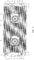
Die
In diesem Ausführungsbeispiel ist das dritte Kühlrohr 33 in drei Abschnitte unterteilt. Die Pumpvorrichtung 40 ist einstückig zwischen jeweils zwei benachbarten Abschnitten des dritten Kühlrohrs 33 angeordnet. Mit zwei Pumpvorrichtungen 40 kann der Wasserfluss im dritten Kühlrohr 33 weiter beschleunigt werden, um die Effizienz der Wärmeableitung weiter zu verbessern und einen besseren Wärmeableitungseffekt zu erzielen.In this embodiment, the
Das Funktionsprinzip dieses Ausführungsbeispiels entspricht jenem des oben beschriebenen ersten Ausführungsbeispiels, so dass das Funktionsprinzip dieses Ausführungsbeispiels hier nicht detailliert beschrieben wird.The operating principle of this embodiment corresponds to that of the first embodiment described above, so that the operating principle of this embodiment is not described in detail here.
BezugszeichenlisteReference List
- 1010
- Wasserverteilkastenwater distribution box
- 1111
- Erste TrennwandFirst partition
- 1212
- Erstes KastengehäuseFirst box body
- 1313
- Erster KastendeckelFirst box lid
- 101101
- Wasserzulaufkammerwater inlet chamber
- 102102
- Übergangskammertransition chamber
- 103103
- Wasserablaufkammerwater drainage chamber
- 104104
- Wasserzulaufwater inlet
- 105105
- Wasserablaufwater drainage
- 106106
- Erste MontagenutFirst mounting groove
- 107107
- Zweite MontagenutSecond mounting groove
- 108108
- Dritte MontagenutThird mounting groove
- 2020
- Wasserauffangbehälterwater collection tank
- 2121
- Zweite TrennwandSecond partition
- 2222
- Zweites KastengehäuseSecond box body
- 2323
- Zweiter KastendeckelSecond box lid
- 201201
- Erste WasserauffangkammerFirst water collection chamber
- 202202
- Zweite WasserauffangkammerSecond water collection chamber
- 203203
- Vierte MontagenutFourth mounting groove
- 204204
- Fünfte MontagenutFifth mounting groove
- 3131
- Erstes KühlrohrFirst cooling tube
- 3232
- Zweites KühlrohrSecond cooling tube
- 3333
- Drittes KühlrohrThird cooling tube
- 3434
- Viertes KühlrohrFourth Cooling Tube
- 4040
- Pumpvorrichtungpumping device
- 4141
- Hauptkastengehäusemain box body
- 411411
- Unterer Kastenlower box
- 412412
- Obere AbdeckungTop cover
- 4242
- Wasserpumpendeckelwater pump cover
- 421421
- Aussparungrecess
- 4343
- Haupttrennwandmain partition
- 431431
- Drittes DurchgangslochThird through hole
- 4444
- Wasserpumpewater pump
- 4545
- LaufradWheel
- 4646
- Dichtungsringsealing ring
- 4747
- Leiterplattecircuit board
- 4848
- Stromkabelpower cord
- 401401
- Wasserpumpenraumwater pump room
- 402402
- Wasserzulaufhohlraumwater inlet cavity
- 403403
- Wasserablaufhohlraumwater drainage cavity
- 404404
- Sechste MontagenutSixth mounting groove
- 405405
- Siebte MontagenutSeventh mounting groove
- 406406
- Erstes BefestigungslochFirst mounting hole
- 407407
- Zweites BefestigungslochSecond mounting hole
- 408408
- Erstes DurchgangslochFirst through hole
- 409409
- Zweites DurchgangslochSecond through hole
- 5151
- Wasserzulauf-Rohrverbindungwater inlet pipe connection
- 5252
- Wasserablauf-RohrverbindungWater drain pipe connection
- 6060
- Kühlrippecooling fin
- 7070
- Lüfterhalterungfan mount
- 8181
- Wasserzulaufrohrwater inlet pipe
- 8282
- Wasserablaufrohrwater drain pipe
- 8383
- Wasserkühlungsblockwater cooling block
- 8484
- Elektronisches Bauteilelectronic component
Claims (10)
Translated fromGermanApplications Claiming Priority (2)
| Application Number | Priority Date | Filing Date | Title |
|---|---|---|---|
| CN202011427259.6 | 2020-12-09 | ||
| CN202011427259.6ACN112393626B (en) | 2020-12-09 | 2020-12-09 | Liquid cooling water discharge with multiple water inlet channels, multiple water collection boxes and water pumps |
Publications (2)
| Publication Number | Publication Date |
|---|---|
| DE102021105438A1true DE102021105438A1 (en) | 2022-06-09 |
| DE102021105438B4 DE102021105438B4 (en) | 2024-10-24 |
Family
ID=74624833
Family Applications (1)
| Application Number | Title | Priority Date | Filing Date |
|---|---|---|---|
| DE102021105438.9AActiveDE102021105438B4 (en) | 2020-12-09 | 2021-03-05 | HEAT DISSIPATION DEVICE FOR LIQUID COOLING |
Country Status (5)
| Country | Link |
|---|---|
| US (1) | US11248848B1 (en) |
| JP (1) | JP7045110B1 (en) |
| CN (1) | CN112393626B (en) |
| DE (1) | DE102021105438B4 (en) |
| TW (1) | TWI753753B (en) |
Families Citing this family (10)
| Publication number | Priority date | Publication date | Assignee | Title |
|---|---|---|---|---|
| US12158307B2 (en)* | 2015-11-12 | 2024-12-03 | Shenzhen APALTEK Co., Ltd. | Internal circulation water cooling heat dissipation device |
| CN113242680A (en)* | 2021-05-28 | 2021-08-10 | 惠州汉旭五金塑胶科技有限公司 | Liquid cooling radiator capable of improving radiating effect |
| CN113490372B (en)* | 2021-07-14 | 2023-03-28 | 南京盈呗信息科技股份有限公司 | Industry thing networked control case |
| TWM623656U (en)* | 2021-10-06 | 2022-02-21 | 志合訊息股份有限公司 | Liquid-cooled notebook computer and its power supply device |
| CN114447814A (en)* | 2022-02-22 | 2022-05-06 | 国家电网有限公司 | A high-efficiency cooling device for a power cabinet for power communication |
| CN115190751A (en)* | 2022-08-04 | 2022-10-14 | 广东电网有限责任公司 | Cooling unit for FTU box |
| CN117915616A (en)* | 2023-01-31 | 2024-04-19 | 成大旗 | Solar power supply controller based on remote communication |
| CN116520964B (en)* | 2023-05-17 | 2024-02-06 | 东莞汉旭五金塑胶科技有限公司 | Liquid cooling row and liquid cooling heat abstractor of two liquid pumps |
| CN116931698B (en)* | 2023-07-28 | 2024-02-13 | 东莞汉旭五金塑胶科技有限公司 | Integrated liquid cooling radiator |
| CN119072044B (en)* | 2024-07-16 | 2025-04-25 | 深圳市创芯精密科技有限公司 | Lock body mechanism of display module assembly |
Citations (3)
| Publication number | Priority date | Publication date | Assignee | Title |
|---|---|---|---|---|
| US20130299139A1 (en) | 2009-12-15 | 2013-11-14 | Stephen Mounioloux | Radiator with integrated pump for actively cooling electronic devices |
| US20160234968A1 (en) | 2015-02-10 | 2016-08-11 | Dynatron Corporation | Liquid-Cooled Heat Sink for Electronic Devices |
| US20170367217A1 (en) | 2015-11-12 | 2017-12-21 | Apaltek Co., Ltd. | Liquid Cooling Radiation System and Liquid Radiator Thereof |
Family Cites Families (24)
| Publication number | Priority date | Publication date | Assignee | Title |
|---|---|---|---|---|
| US1306976A (en)* | 1919-06-17 | Herbert u | ||
| US5022465A (en)* | 1989-12-26 | 1991-06-11 | Baines William F | Radiator baffle gasket |
| GB9725621D0 (en)* | 1997-12-03 | 1998-02-04 | Concentric Pumps Ltd | Improvements relating to the liquid cooled i.c. engines |
| JP2004301454A (en)* | 2003-03-31 | 2004-10-28 | Calsonic Kansei Corp | Header tank for heat exchanger |
| CN1746468A (en)* | 2004-06-09 | 2006-03-15 | 鸿富锦精密工业(深圳)有限公司 | The liquid-cooled radiating system micropump |
| TWI272056B (en)* | 2005-08-12 | 2007-01-21 | Foxconn Tech Co Ltd | Integrated liquid cooling system |
| JP4811864B2 (en)* | 2006-08-01 | 2011-11-09 | キャタピラー エス エー アール エル | Cooling system |
| JP5706665B2 (en)* | 2010-10-29 | 2015-04-22 | 株式会社ティラド | Reinforcement structure of heat exchanger |
| MX2012009812A (en)* | 2011-08-23 | 2013-02-22 | Phoenix Mfg Inc | Evaporative condenser cooling unit and method. |
| JP2013100785A (en)* | 2011-11-09 | 2013-05-23 | Daimler Ag | Engine cooling device |
| CN103486880A (en)* | 2013-09-18 | 2014-01-01 | 张伟 | Header thermal fluid flow passage tube cavity water-storage and pressure-bearing heat exchanger and manufacture process thereof |
| TWM477138U (en)* | 2013-12-31 | 2014-04-21 | Kuan Ding Industrial Co Ltd | Liquid cooled heat dissipation device |
| US9021826B1 (en)* | 2014-03-11 | 2015-05-05 | Her Jiu Technology Co., Ltd. | Water energy conversion system |
| KR20160147337A (en)* | 2015-06-15 | 2016-12-23 | 한국생산기술연구원 | Heat exchanger and exhaust heat recovery device using the same |
| CN211656711U (en) | 2019-11-25 | 2020-10-09 | 深圳市研派科技有限公司 | Internal circulation type water-cooling heat dissipation device |
| CN105451518B (en)* | 2015-11-30 | 2018-03-13 | 惠州市泰鼎电子科技有限公司 | Water cooled heat radiating is arranged and its manufacture method, the heat abstractor with radiating row |
| CN206291301U (en)* | 2016-11-17 | 2017-06-30 | 东莞市康源节能科技有限公司 | A kind of heat exchanger type shower house |
| CN106382674A (en)* | 2016-11-17 | 2017-02-08 | 东莞市康源节能科技有限公司 | Heat exchanger type shower room |
| TWM547124U (en)* | 2017-05-26 | 2017-08-11 | Kuan Ding Technology Co Ltd | Water-cooling heat dissipation device |
| CN109213294A (en)* | 2017-07-03 | 2019-01-15 | 泽鸿(广州)电子科技有限公司 | Water cooling with built-in water pump arranges module |
| CN210181547U (en)* | 2019-07-31 | 2020-03-24 | 深圳市万景华科技有限公司 | Water-cooling radiator |
| CN110831411B (en)* | 2019-11-18 | 2021-07-13 | 深圳市研派科技有限公司 | Liquid Cooling Units with Compound Flow Paths |
| US20210180890A1 (en)* | 2019-12-13 | 2021-06-17 | Shenzhen Wan Jing Hua Technology Co., Ltd. | Heat dissipation configuration with water pump assembly |
| CN214407066U (en)* | 2020-12-09 | 2021-10-15 | 惠州汉旭五金塑胶科技有限公司 | Liquid cooling radiating water discharge of water inlet multi-runner multi-water collecting box water adding pump |
- 2020
- 2020-12-09CNCN202011427259.6Apatent/CN112393626B/enactiveActive
- 2021
- 2021-01-20TWTW110102176Apatent/TWI753753B/enactive
- 2021-01-26JPJP2021010609Apatent/JP7045110B1/enactiveActive
- 2021-02-09USUS17/170,903patent/US11248848B1/enactiveActive
- 2021-03-05DEDE102021105438.9Apatent/DE102021105438B4/enactiveActive
Patent Citations (3)
| Publication number | Priority date | Publication date | Assignee | Title |
|---|---|---|---|---|
| US20130299139A1 (en) | 2009-12-15 | 2013-11-14 | Stephen Mounioloux | Radiator with integrated pump for actively cooling electronic devices |
| US20160234968A1 (en) | 2015-02-10 | 2016-08-11 | Dynatron Corporation | Liquid-Cooled Heat Sink for Electronic Devices |
| US20170367217A1 (en) | 2015-11-12 | 2017-12-21 | Apaltek Co., Ltd. | Liquid Cooling Radiation System and Liquid Radiator Thereof |
Also Published As
| Publication number | Publication date |
|---|---|
| CN112393626B (en) | 2025-03-11 |
| TW202119905A (en) | 2021-05-16 |
| JP2022091657A (en) | 2022-06-21 |
| CN112393626A (en) | 2021-02-23 |
| TWI753753B (en) | 2022-01-21 |
| DE102021105438B4 (en) | 2024-10-24 |
| US11248848B1 (en) | 2022-02-15 |
| JP7045110B1 (en) | 2022-03-31 |
Similar Documents
| Publication | Publication Date | Title |
|---|---|---|
| DE102021105438B4 (en) | HEAT DISSIPATION DEVICE FOR LIQUID COOLING | |
| DE102021105437A1 (en) | HIGH EFFICIENCY MULTI-CHANNEL WATER-COOLING RADIATOR | |
| DE102021110297B4 (en) | INTEGRATED LIQUID COOLING RADIATOR | |
| DE102021105436A1 (en) | WATER COOLING RADIATOR WITH BUILT-IN WATER PUMP | |
| DE102007058706B4 (en) | Cooling arrangement and the cooling arrangement exhibiting electrical device | |
| DE602004010422T2 (en) | FLOW DISTRIBUTION UNIT AND COOLING UNIT | |
| DE102016001966B4 (en) | Air-cooled laser device with heat transfer component having cooling fins | |
| EP1340417B1 (en) | Electronics arrangement | |
| DE102016001965A1 (en) | Air-cooled laser device with cooling fins, L-shaped heat transfer element | |
| DE102014105960A1 (en) | LED lighting device with an improved heat sink covered | |
| EP0015997B1 (en) | Device for cooling dissipation heat producing electric and/or electronic elements | |
| DE112006003825T5 (en) | Electric current transformer device | |
| DE202015105830U1 (en) | Water cooling device for heat dissipation and associated water block | |
| DE112006003812T5 (en) | cooler | |
| DE202010006577U1 (en) | Cooling module for vehicle battery | |
| DE102023123631A1 (en) | LIQUID COOLING HEAT DISSIPATION DEVICES | |
| DE112011101959B4 (en) | Heat sink and process for its production | |
| DE202015103469U1 (en) | Assemblable water cooler | |
| DE102023112917B3 (en) | LIQUID COOLER | |
| WO2018210364A1 (en) | Heat exchange module | |
| DE202016107386U1 (en) | The cooling device of the graphics card | |
| DE102020213189B4 (en) | Control cabinet with fan module | |
| DE202018100040U1 (en) | Water cooler assembly | |
| DE202015001472U1 (en) | Liquid-cooled heat sink for electronic devices | |
| DE202017100139U1 (en) | door cooler |
Legal Events
| Date | Code | Title | Description |
|---|---|---|---|
| R012 | Request for examination validly filed | ||
| R016 | Response to examination communication | ||
| R016 | Response to examination communication | ||
| R018 | Grant decision by examination section/examining division | ||
| R020 | Patent grant now final |